RAM P/N AH04415R Double Reduction Wheel Drive SERVICE MANUAL
|
|
|
- Jemima O’Neal’
- 5 years ago
- Views:
Transcription
1
2
3
4
5
6
7
8
9
10
11
12
13
14
15
16
17
18
19
20
21
22
23
24

25
26
27
28
29
30
31
32
33
34
35
36
37
38
39
40
41
42
43
44
45
46
47
48
49
50
51
52 RAM P/N AH04415R Double Reduction Wheel Drive SERVICE MANUAL
53 Power Wheel Service Manual Model 7 Double Reduction Wheel Drives AUBURN, INDIANA U.S.A. PHONE: (219) FAX: (219) OPTIONAL
54 DISASSEMBLY OF WHEEL DRIVE Refer to Parts Illustration STEP 1 Slide the coupling (1) from splines on input shaft (2). STEP 2 Position the assembly upright on face of spindle (3). STEP 3 Remove the disengage cover (31) if necessary. STEP 4 Remove eight bolts (29) and the large cover (28) from the unit. The thrust washer (25) and the disengage plunger (26) usually remain attached to the large cover (28) when it is removed. Remove thrust washer (25), disengage plunger (26) and O ring (27) from the large cover (28). STEP 5 Remove primary sun gear (24) from end of input shaft (2). STEP 6 Remove the primary carrier assembly (22). STEP 7 Remove the secondary carrier assembly (21). STEP 8 Remove the input shaft (2) from spindle (3). Remove the retaining rings (17), washers (18), and disengage spring (19) from input shaft (2) only if replacement is required. STEP 9 One tab of lock washer (15) will be engaged in slot of bearing nut (16); bend back to release. Remove the bearing nut (16), lock washer (15) and thrust washer (14). Note: A special locknut wrench, 596Z, is required for the removal of the bearing locknut. Contact RAM Winch and Hoist for procurement of wrench and other service tools. STEP 10 Bolt spindle drive tool, 598FF, to ring gear (20). Grade 8 bolts should be used. Drive spindle (3) from hub (11) by turning center bolt of spindle drive tool. Care should be taken to avoid damaging splines and threads on spindle. Note: Bearing cone (13) has been designed with a press fit with respect to spindle (3). Considerable force will be required to remove cone from spindle. STEP 11 Remove spindle drive tool from ring gear (20). STEP 12 Remove the 18 bolts (9) and washers (10) from hub (11) and remove ring gear (20). It may be necessary to strike ring gear (20) with a rubber mallet to loosen from hub (11). STEP 13 Remove the boot seal (4) and oil seal (5) and bearing cones (6 & 13) from hub (11). Inspect bearing cups (7 & 12) in position and remove only if replacement is required.
55 Power Wheel Service Manual Model 7 Double Reduction Wheel Drives AUBURN, INDIANA U.S.A. PHONE: (219) FAX: (219) OPTIONAL
56 ASSEMBLY OF WHEEL DRIVE Refer to Parts Illustration STEP 1 Press new bearing cups (7 & 12) in each side of the hub (11). It is recommended that bearing cups (7 & 12) and cones (6 & 13) be replaced in sets. STEP 2 Assemble bearing cone (6) into cup (7) at seal end of hub (11) and press a new seal (5) into hub (11). Install boot seal (4) on hub (11) if unit is so equipped. STEP 3 Position spindle (3) upright on bench. Lubricate lips of seal (5) and lower hub (11) onto spindle (3). Hub (11) should be centered as it is lowered over spindle (3) to prevent seal damage. STEP 4 Assemble bearing cone (13) over spindle (3). Press bearing cone (13) over spindle bearing journal using press and cylindrical bearing cone driver 598E. Press bearing cone (13) down until rollers just touch cup (12). Take care to avoid pressing cone (13) too far. Note: If a press is not available, place tool 598E over splined end of spindle (3) on the edge of bearing cone (13) and drive into place with hammer or mallet. If this method is used, care nut be taken to avoid damage to bearing cone and spindle. STEP 5 Install thrust washer (14) with tab in keyway of spindle and bearing nut (16). DO NOT install lock washer (15) at this time. STEP 6 Clean mating surfaces and apply a bead of silicone sealant to face of hub (11) that mates with ring gear (20). See instructions on sealant package. Hub (11) is attached to ring gear (20) with 18 3/8-24 grade 8 hex head cap screws (9) and flat washers (10). Torque cap screws to lb.-ft. (70 81 Nm). STEP 7 Place spindle drive tool, 598FF, over spindle (3) and bolt or pin to ring gear (20). Make sure center bolt of drive tool is not touching spindle and is prevented from rotating by jam nuts provided on tool. STEP 8 Check initial rolling torque by installing a lb. in. torque wrench (arm or dial type) on center nut of spindle drive tool and turning hub (11) slowly and steadily with the torque wrench. Note mean torque. An initial bearing torque of greater than 52 lb. in. with boot seal installed or 46 lb. in. without boot seal means that the cone (13) was pressed on too tightly in step 4. In this case, back off bearing cone (13) by pressing spindle (3) out of cone (13) until initial preload is relieved. See step 10 disassembly procedure. STEP 9 Torque bearing nut (16) with bearing nut wrench 596Z until a bearing rolling torque of lb. in., with a boot seal installed, or lb. in., without a boot seal is reached. This may require several trials of pressing the cone (13) by torquing the nut (16) and then checking the rolling torque. Rotate hub (11) by hand as nut is being tightened in order to seat bearings. Note: Up to 250 lb. ft. of torque may have to be applied to bearing nut (16) in order to press cone (13) into position. STEP 10 Remove bearing nut (16) and install lock washer (15). Replace bearing nut (16).
57 Power Wheel Service Manual Model 7 Double Reduction Wheel Drives AUBURN, INDIANA U.S.A. PHONE: (219) FAX: (219) OPTIONAL
58 Refer to Parts Illustration STEP 11 Re-torque bearing nut (16) to lb. ft. (80-94 Nm). STEP 12 Secure bearing nut (16) by bending a lock washer (15) tab into one of four bearing nut slots. If no tab aligns with a slot, the nut may be tightened until one of the slots aligns with a lock washer tab. STEP 13 Assemble a washer (18), spring (19), a second washer (18), and a retaining ring (17) in the middle grooves of input shaft (2). Install a second retaining ring (17) in groove near small end of input shaft (2). STEP 14 Assemble the splined end of the input shaft (2) down into spindle (3). STEP 15 Assemble the secondary carrier assembly (21) to spindle (3) at splines. STEP 16 Assemble the primary carrier assembly (22) into the ring gear (20). It will be necessary to rotate carrier to align secondary sun gear {part of primary carrier assembly (22)} with planet gear teeth in secondary carrier assembly (21). Assemble primary sun gear (24) over input shaft (2). Rotate primary sun gear (24) to align input shaft (2) to gear splines and gear teeth in primary carrier assembly (22). STEP 17 Lubricate O ring (27) and assemble in groove inside cover hole, push disengage plunger (26) into cover (28) with pointed end facing inside of unit. STEP 18 Assemble the thrust washer (25) with tangs engaged with cover (28). Note: A small amount of grease applied to the backside of thrust washer (25) will hold washer in place. Apply a bead of silicone sealant to end of face of ring gear (20). Assemble cover (28) aligning holes of cover and ring gear. Assemble the eight 5/16 18 x 1 inch hex head bolts (29). Torque bolts to lb. ft. (27 34 Nm). STEP 19 Assemble the disengage cover (31) with dimpled center protruding out if wheel is to be used to drive the vehicle. Assemble and torque the two 5/16 18 x ½ inch bolts (32). Torque bolts to lb. ft. (13 27 Nm). STEP 20 Invert the Wheel Drive assembly and assemble the coupling (1), with counter bore out, to the input shaft (2). STEP 21 After motor is assembled to drive or drive is sealed at spindle, fill with lubricant to proper level and replace all plugs. Note: When installing a hydraulic motor to the Wheel Drive it is necessary to place an O ring or gasket between the motor and the planetary drive. O ring sizes: SAE A 2-042, SAE B 2-155, SAE C
59
60 CARRIER ASSEMBLIES It is recommended that the primary and secondary carrier assemblies (21 & 22) be serviced entirely to protect the integrity of the Wheel Drive. LUBRICATION RECOMMENDATIONS IMPORTANT: WHEEL DRIVES ARE SHIPPED WITHOUT LUBRICANT AND MUST BE FILLED TO THE PROPER LEVEL PRIOR TO START UP. Observe lubrication recommendations given by the original equipment manufacturer. When specific recommendations are not available, use mild extreme pressure lubricant API-GL-5, No. 80 or 90 when filling the Wheel Drive under normal temperature ranges between F (-18 to 49 C). Wheel Drive is to be half full of oil when unit is mounted level and horizontal. Use drain and fill plugs located in cover and ring gear. Oil is to be changed after first 50 hours of operation with subsequent changes every 1000 hours or yearly, which ever comes first. If unit is to be operated vertically, if ambient conditions are outside the specified range, or if the oil temperature exceeds 200 F (93 C) contact RAM Winch & Hoist for oil and level recommendations. STORAGE A protective film is applied to the Wheel Drive at the factory to prevent rust during shipment. Additional protection may be required if the Wheel Drive is to be stored for an extended period of time. SEALING COMPOUND Silastic RTV732 sealer and General Electric Silimate RTV No or RTV No are currently recommended for sealing gasket surfaces. Sealant should be applied in continuous bead, which should be centered on the surface to be sealed but should move to the inside of the hole at each bolthole location. For service requirements order RAM Winch & Hoist part number SPECIFICATIONS Maximum intermittent output torque... 70,000 lb. In. (7,910 Nm) Maximum input speed... 5,000 RPM Oil capacity oz (920 ml)
61 Power Wheel Service Manual Model 7 Double Reduction Wheel Drives AUBURN, INDIANA U.S.A. PHONE: (219) FAX: (219) OPTIONAL
62 PARTS LISTING Refer to Parts Illustration Drawing for Item Numbers Item No. Description No. Used in Ass y. Item No. Description No.Used in Ass y. 1 Coupling 1 19 Disengage Spring Input Shaft 1 20 Ring Gear 1 3 Spindle 1 21 Secondary Carrier Assembly 1 4 Boot Seal Primary Carrier Assembly 1 5 Oil Seal Retaining Ring 1 6 Bearing Cone Primary Sun Gear 1 7 Bearing Cup Thrust Washer 1 8 Wheel Bolt 9 26 Disengage Plunger Hex Head Bolt (Grade 8) O Ring Flat Washer Large Cover 1 11 Hub 1 29 Hex Head Bolt 8 12 Bearing Cup Magnetic Plug Bearing Cone Disengage Cover Thrust Washer Hex Head Bolt 2 15 Lock Washer Quick Disconnect Gasket 1 16 Bearing Nut Quick Disconnect Assembly 1 17 Retaining Ring 2 35 Hex Head Bolt 2 18 Washer 2 Contact RAM Winch & Hoist at (281) with model number, item number and description to obtain the appropriate parts. Refer to parts listing for the specific item numbers and quantities. Wheel Drive Service Kits Part No. Description Included Items 596Z Bearing Locknut Tool Not Shown 598E Bearing Cone Driver Not Shown 598FF Spindle/Shaft Drive Tool Not Shown
63
64
65
66
67
68
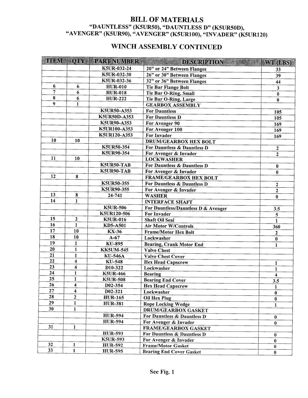
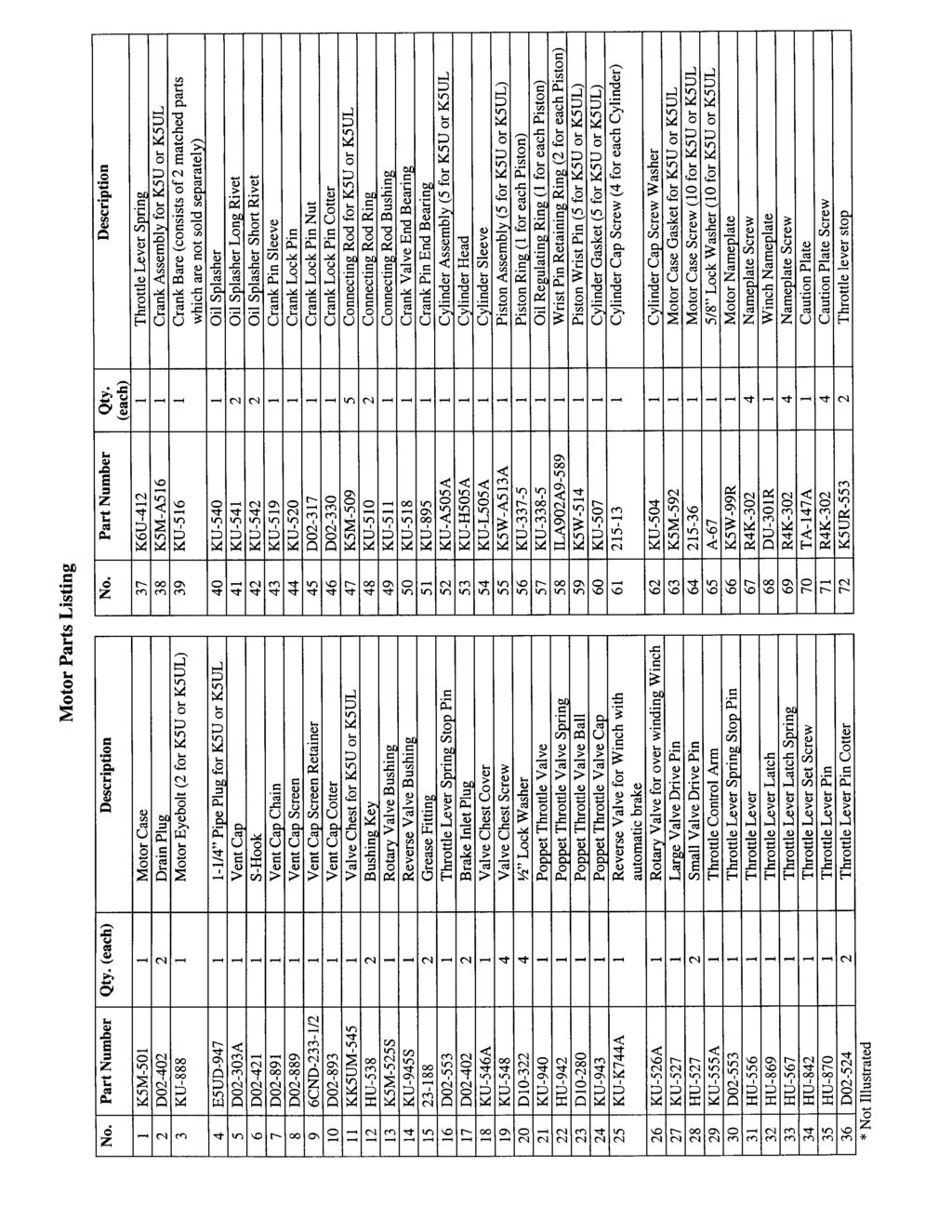
69 K5UR50DML Air Winch RAM Winch & Hoist
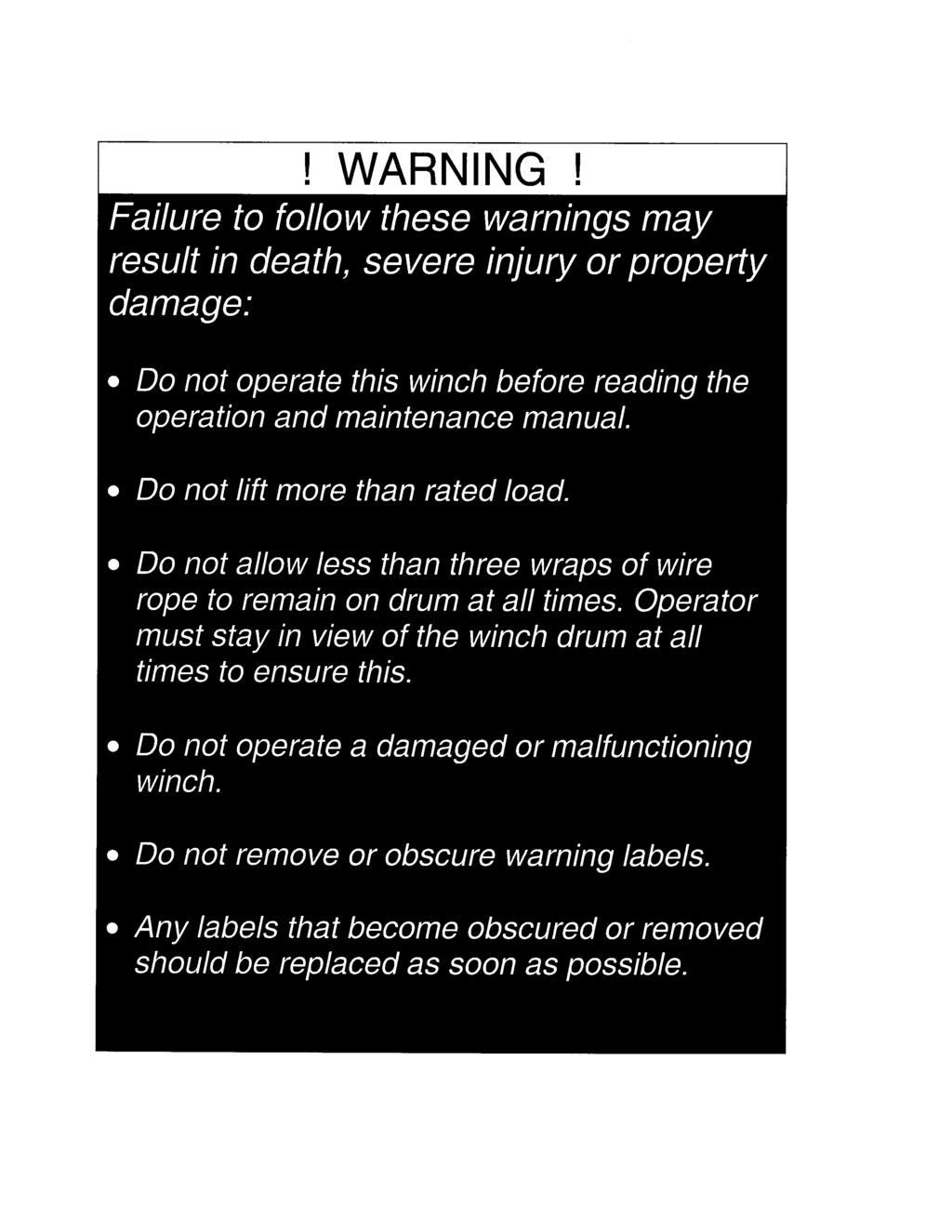
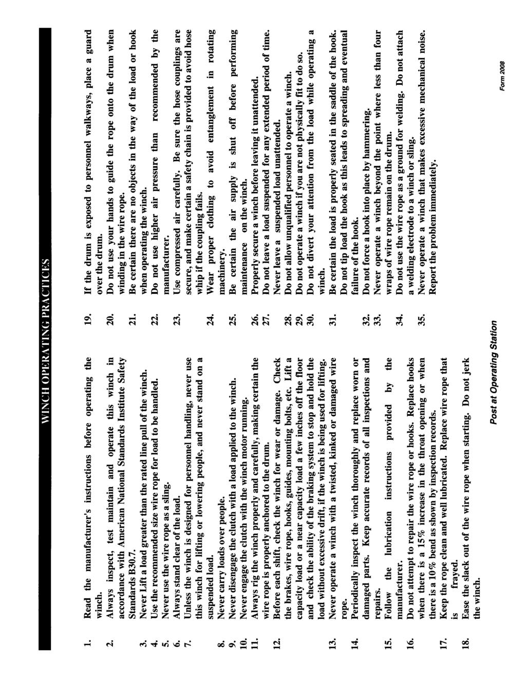
INVADER MODEL K5UR100ML UTILITY AND MANLIFTER AIR WINCH. Warning! Review WINCH OPERATING PRACTICES Prior to use.
 Instructions, Parts and Maintenance Manual INVADER MODEL K5UR100ML UTILITY AND MANLIFTER AIR WINCH Warning! Review WINCH OPERATING PRACTICES Prior to use. Always operate, inspect and maintain this winch
SPIT TFIRE AIR WARNING! Review
 INSTRUCTIONS, PARTS AND MAINTENANCE MANUAL SPIT TFIRE H5UR50-18MX1 UTILITY AIR WINCH WARNING! Review WINCH OPERATING PRACTICES prior to use. Always operate, inspect and maintain this winch in accordance
3.2 DRIVE TORQUE HUB. Roll, Leak and Brake Testing SECTION 3 - CHASSIS & TURNTABLE. 3-2 JLG Lift
 3.2 DRIVE TORQUE HUB Roll, Leak and Brake Testing 10 LUG PATTERN Torque-Hub units should always be roll and leak tested before disassembly and after assembly to make sure that the unit's gears, bearings
1984 Dodge W250 PICKUP
 1984 Dodge W250 PICKUP Submodel: Engine Type: V8 Liters: 5.2 Fuel Delivery: CARB Fuel: GAS Dana 44 MODELS THROUGH 1984 2. Raise and safely support the vehicle, then remove the wheel hub and bearings as
Torque-Hub Planetary Final Drive S12A1 & 2 Series Service Manual
 Torque-Hub Planetary Final Drive S12A1 & 2 Series Service Manual Rev 8/30/13 1 While every precaution has been taken in the preparation of this document, Fairfield Manufacturing Co. Inc. assumes no liability
Service Manual. Example Part Number. Motor Supplier. Motor Number. Model. Bail Boss. Ratio. Shaft
 Service Manual 50 Series Digger models Example Part Number 50 05 f 54 Model Ratio Shaft Bail Boss Motor Supplier Motor Number This service manual is effective: S/N: 58670 to current date: 9-003 to CURRENT
SISU DP-330 DRIVE GEAR. Maintenance Manual
 SISU DP-330 DRIVE GEAR Maintenance Manual Sisu Axles, Inc. Autotehtaantie 1 PO Box 189 Fin-13101 Hameenlinna Finland Phone +358 204 55 2999 Fax +358 204 55 2900 DP330DG.PDF (3/2007) TABLE OF CONTENTS
GM 3000 AIRLESS PAINT SPRAYERS Drive Housing Replacement Kit Pinion Housing Replacement Kit
 INSTRUCTIONS 08660 INSTRUCTIONS This manual contains important warnings and information. READ AND KEEP FOR REFERENCE. Rev. B GM 000 AIRLESS PAINT SPRAYERS Drive Housing Replacement Kit 869 Pinion Housing
CHAPTER 15 WINCH MAINTENANCE. This chapter contains maintenance instructions for disassembly and repair of winch components at the Direct
 CHAPTER 15 WINCH MAINTENANCE This chapter contains maintenance instructions for disassembly and repair of winch components at the Direct 15-1. INTRODUCTION Support maintenance level. Some subassemblies
LIMITED SLIP DIFFERENTIAL INSTALLATION
 Installation of the limited slip gear can be done with axle out of car or with car lifted to gain access from underneath. Refer to repair manual for proper lifting instructions if car is to be lifted.
 Page 1 of 6 Axle Shaft, Hub, Oil Seal and Outer Wheel Bearing SPECIAL SERVICE TOOL(S) REQUIRED Description Tool Number Locknut Wrench T85T-4252-AH Removal 1. Set the parking brake and loosen the eight
2001 Dodge RAM 3500 PICKUP
 1 of 76 9/14/2012 7:02 PM 2001 Dodge RAM 3500 PICKUP Submodel: Engine Type: L6 Liters: 5.9 Fuel Delivery: FI Fuel: DIESEL Subarticles MANUAL- NV3500 - DISASSEMBLY MANUAL- NV3500 - DISASSEMBLY MANUAL -
Gear Products Inc N. 161st E. Ave. Tulsa, OK Phone (918) Fax (918)
 Fax (918)") SERVICE MANUAL Disassembly & Assembly Procedures Worm Gear Swing Drive 003 Series Gear Products Inc. 1111 N. 161st E. Ave. Tulsa, OK 74116 Phone (918) 234-3044 Fax (918) 234-3455 Worm Gear Swing Drive
SERVICE MANUAL Disassembly & Assembly Procedures Worm Gear Swing Drive 003 Series Gear Products Inc. 1111 N. 161st E. Ave. Tulsa, OK 74116 Phone (918) 234-3044 Fax (918) 234-3455 Worm Gear Swing Drive
Premier Augers East Pontiac Street Fort Wayne, IN Hydraulic Earth Auger Operator s Manual. Serial Number Model Number
 Premier Augers 1631 East Pontiac Street Fort Wayne, IN 46803 866-458-0008 Hydraulic Earth Auger Operator s Manual Serial Number Model Number Models H005PD, H010PD, H015PD, H019PD, H024PD Warning Avoid
Amarillo PUMP DRIVES (250 HP THROUGH 350 HP) INSTRUCTIONS FOR REPAIRING MODELS 250, 300, and 350
 INSTRUCTIONS FOR REPAIRING MODELS 250, 300, and 350") Amarillo PUMP DRIVES (250 HP THROUGH 350 HP) INSTRUCTIONS FOR REPAIRING MODELS 250, 300, and 350 Amarillo Right Angle Pump Drives, if properly installed and maintained, should provide years of service
Amarillo PUMP DRIVES (250 HP THROUGH 350 HP) INSTRUCTIONS FOR REPAIRING MODELS 250, 300, and 350 Amarillo Right Angle Pump Drives, if properly installed and maintained, should provide years of service
TC20 Chain Driven Power Take-Off Overhaul Instructions
 TC20 Chain Driven Power Take-Off Overhaul Instructions Table of Contents Section Page Introduction 4 Ordering Repair Parts 4 General Information 5 Special Tools 6 Disassembly See Page 2 Reassembly See
LIFT TRUCK SERIES: G35S-2 G40S-2 G45S-2 G40SC-2 G45SC-2 G50SC-2. November 15, 2000 CODE 3150 LT3150-L0 SUBJECT: NEW DRIVE AXLE
 LIFT TRUCK SERIES: G35S-2 G40S-2 G45S-2 G40SC-2 G45SC-2 G50SC-2 November 15, 2000 CODE 3150 LT3150-L0 SUBJECT: NEW DRIVE AXLE A new drive axle has been introduced in the above model lift trucks. The purpose
Torque-Hub Planetary Final Drive 7000 Series Service Manual with Brakes
 Torque-Hub Planetary Final Drive 7000 Series Service Manual with Brakes Rev 12/03/12 1 While every precaution has been taken in the preparation of this document, Fairfield Manufacturing Co. Inc. assumes
Swing Drive SMCS ;
 Unfiled Notes Page 1 Service Information System Friday, May 06, 2016 8:43 AM Disassembly and Assembly E110B EXCAVATOR VEHICLE SYSTEMS Media Number -SENR4576-01 Publication Date -01/06/2005 Date Updated
Mini-Skid Hydraulic Earth Auger Attachments. Models: MS09, MS12, MS11, MS14, MS18 OPERATOR S MANUAL. Serial Number Model Number
 Mini-Skid Hydraulic Earth Auger Attachments Models: MS09, MS12, MS11, MS14, MS18 OPERATOR S MANUAL Serial Number Model Number WARNING! Avoid injury or death. Read and understand this entire manual before
OPERATOR S MANUAL Serial Number Model Number
 Hydraulic Earth Auger Attachments Models: MD06PD, MD09PD, MD12PD, MD14PD, MD18PD OPERATOR S MANUAL Serial Number Model Number WARNING! Avoid injury or death. Read and understand this entire manual before
Installation Instructions for the Tera low range Dana 20 (LOW20)
") Installation Instructions for the Tera low range Dana 20 (LOW20) Tera Manufacturing, Inc. 5251 South Commerce Dr. Murray, Utah 84107 Phone/801.288.2585 Fax/801.288.2571 www.teraflex.biz Attention: Verify
Installation Instructions for the Tera low range Dana 20 (LOW20) Tera Manufacturing, Inc. 5251 South Commerce Dr. Murray, Utah 84107 Phone/801.288.2585 Fax/801.288.2571 www.teraflex.biz Attention: Verify
9.1 Assembled Planetary Gearbox
 SEC. 9 GEARBOX 9.1 Assembled Planetary Gearbox SEC. 9 GEARBOX Page 1 9.1 Assembley Gearbox Drawing 9.1.1. Drawing #11236 - Gearbox, Planetary SEC. 9 GEARBOX Page 2 9.2. Assembly Lower Output Shaft and
Off-Highway Axle Planetary Wheel Ends
 Maintenance Manual MM-1189 Off-Highway Axle Planetary Wheel Ends Revised 06-16 Service Notes About This Manual This manual provides service and repair procedures for planetary wheel ends on off-highway
Inspection and Verification, Ranger
 file://c:\tso\tsocache\vdtom_5368\svk~us~en~file=svk53a03.htm~gen~ref.htm Page 1 of 1 Section 05-03A: Wheel Hubs and Bearings, Front Wheels, 4- Wheel Drive DIAGNOSIS AND TESTING 1997 Ranger 4x4 with Dana
Steering Gear: Service and Repair POWER STEERING GEAR BOX
 2003 Kia Truck Sorento V6-3.5L Copyright 2013, ALLDATA 10.52 Page 1 Steering Gear: Service and Repair POWER STEERING GEAR BOX COMPONENTS REMOVAL 1. Drain the power steering fluid. 2. Disconnect the pressure
SECTION Front Drive Axle/Differential
 205-03-i Front Drive Axle/Differential 205-03-i SECTION 205-03 Front Drive Axle/Differential CONTENTS PAGE Axle... 205-03-2 205-03-2 Front Drive Axle/Differential 205-03-2 Axle Special Tool(s) C-Frame
DRIVE AXLE Nissan 240SX DESCRIPTION & OPERATION AXLE RATIO & IDENTIFICATION AXLE SHAFT & BEARING R & I DRIVE SHAFT R & I
 DRIVE AXLE 1990 Nissan 240SX 1990 DRIVE AXLES Rear Axle - R200 240SX, 300ZX DESCRIPTION & OPERATION The axle assembly is a hypoid type gear with integral carrier housing. The pinion bearing preload adjustment
MANUAL TRANS OVERHAUL - BORG-WARNER - T56 6-SPEED MANUAL TRANSMISSIONS Borg-Warner T56 (MM6) 6-Speed
 6-Speed") IDENTIFICATION MANUAL TRANS OVERHAUL - BORG-WARNER - T56 6-SPEED 1998 MANUAL TRANSMISSIONS Borg-Warner T56 (MM6) 6-Speed Transmission has 2 identification labels, located on lower left side of case. One
IDENTIFICATION MANUAL TRANS OVERHAUL - BORG-WARNER - T56 6-SPEED 1998 MANUAL TRANSMISSIONS Borg-Warner T56 (MM6) 6-Speed Transmission has 2 identification labels, located on lower left side of case. One
DISASSEMBLY AND ASSEMBLY
 205-03-1 Front Drive Axle/Differential Ford 8.8-Inch Ring Gear 205-03-1 DISASSEMBLY AND ASSEMBLY Axle Front Drive Special Tool(s) 2-Jaw Puller 205-D072 (D97L-4221-A) Special Tool(s) Carrier Bearing Replacer
TROUBLESHOOTING SPECIAL TOOL ASSEMBLY AND ADJUSTMENT
 1 INDEX Models FD, FE, FF and SG REAR AXLE 10-1 10-108E-07 CHAPTER 10 REAR AXLE Models FD, FE, FF and SG TROUBLESHOOTING...10-2 10 SPECIAL TOOL...10-3 WHEEL HUB AND RELATED PARTS DISASSEMBLY...10-7 INSPECTION...10-9
STEERING SYSTEM - MANUAL RACK & PINION
 STEERING SYSTEM - MANUAL RACK & PINION 1993 Nissan Sentra 1993 STEERING Nissan Manual Rack & Pinion NX, Sentra DESCRIPTION & OPERATION Steering gear assembly is a manual rack and pinion type. Unit is mounted
AMARILLO PUMP DRIVES MODEL 1 OOOA, 1200, 1500, 1800
 AMARILLO PUMP DRIVES MODEL 1 OOOA, 1200, 1500, 1800 INSTRUCTIONS FOR REPAIRING MARCH 1, 1993 AMARILLO GEAR COMPANY Post Office Box 1789, Amarillo, Texas 79105 806 / 622-1273 FAX 806 / 622-3258 INSTRUCTIONS
TRANSFER CASE Mitsubishi Montero APPLICATION DESCRIPTION TESTING 4WD INDICATOR CONTROL UNIT (MONTERO) DETECTION SWITCH
 DETECTION SWITCH") TRANSFER CASE 1993 Mitsubishi Montero 1991-94 TRANSFER CASES Mitsubishi Dodge; Ram-50 Mitsubishi; Pickup, Montero APPLICATION TRANSFER CASE APPLICATIONS TABLE Application (1) Transmission Model Dodge 1991-93
TRANSFER CASE 1993 Mitsubishi Montero 1991-94 TRANSFER CASES Mitsubishi Dodge; Ram-50 Mitsubishi; Pickup, Montero APPLICATION TRANSFER CASE APPLICATIONS TABLE Application (1) Transmission Model Dodge 1991-93
MARLIN CRAWLER FRONT CHROMOLY OUTPUT SHAFT
 F r o n t C h r o m o l y O u t p u t 1 MARLIN CRAWLER FRONT CHROMOLY OUTPUT SHAFT FOREWORD This Installer shows how to install our 30-spline Front Chromoly Output Shaft into a Toyota 1979-95 gear drive
Power Wheel Model 8 Series B Planetary Gear Drives AuburnGear.com
 Power Wheel Model 8 Series B Planetary Gear Drives 260.92.30 AuburnGear.com SERIES B WHEEL DRIVES Model 8 Series B Features & A2 Integral Brake Information...3 Double Reduction...4 with A2 Series Integral
DRIVE AXLE - INTEGRAL HOUSING
 DRIVE AXLE - INTEGRAL HOUSING 1993 Toyota Celica 1993 DRIVE AXLES Toyota Differentials & Axle Shafts - Integral Housing Toyota; Celica All-Trac DESCRIPTION Drive axle assembly is a hypoid type with integral
1999 F-150/250 Workshop Manual
 Page 1 of 30 SECTION 205-03: Front Drive Axle/Differential Ford 8.8-Inch Ring Gear 1999 F-150/250 Workshop Manual DISASSEMBLY AND ASSEMBLY Procedure revision date: 01/08/2003 Axle Front Drive Special Tool(s)
Maintenance Information
 45528270 Edition 1 June 2007 Barring Motor T480 Series Maintenance Information Save These Instructions WARNING Always wear eye protection when operating or performing maintenance on this Barring Motor.
Model: D5H TRACK-TYPE TRACTOR 8RC02018 Configuration: D5H & D5H LGP TRACTOR / POWER SHIFT / 8RC (MACHINE) POWERED BY 3304 ENGINE
 POWERED BY 3304 ENGINE") Model: D5H TRACK-TYPE TRACTOR 8RC02018 Configuration: D5H & D5H LGP TRACTOR / POWER SHIFT / 8RC00001-03999 (MACHINE) POWERED BY 3304 ENGINE Disassembly and Assembly D5H AND D5H SERIES II TRACTORS POWER
Model: D5H TRACK-TYPE TRACTOR 8RC02018 Configuration: D5H & D5H LGP TRACTOR / POWER SHIFT / 8RC00001-03999 (MACHINE) POWERED BY 3304 ENGINE Disassembly and Assembly D5H AND D5H SERIES II TRACTORS POWER
TRANSMISSION AND TRANSFER CASE
 XJ TRANSMISSION AND TRANSFER CASE 21-1 TRANSMISSION AND TRANSFER CASE TABLE OF CONTENTS page AX5 MANUAL TRANSMISSION... 1 NV3550 MANUAL TRANSMISSION... 42 AUTOMATIC TRANSMISSION 30RH... 88 page AW 4 AUTOMATIC
Power Wheel. 1:1 Drives/Bearing Housings
 Power Wheel 1:1 Drives/Bearing Housings 260.925.3200 AuburnGear.com Table of Contents Power Wheel 1:1 Features...3 Model 6B 1:1 Direct Drives...4 Model 8B 1:1 8T2 Direct Drives...6 Model 8B 1:1 8S2 Direct
INSTRUCTIONS. Disassembly. Shifter Cam Assembly. Shifter Forks
 INSTRUCTIONS Disassembly To protect against accidental start-up of vehicle, always disconnect the negative battery cable before working on the motorcycle. Failure to disconnect the battery cable could
INSPECTION DF 80. Install the rear differential side gear and rear differential spider onto the differential case RH.
 80 INSPECTION 1. INSPECT DIFFERENTIAL PINION AND SIDE GEAR (a) Check that there is no damage to the differential pinion or differential side gear. If the differential pinion and/or differential side gear
Power Wheel Model 8 Planetary Gear Drives AuburnGear.com
 Power Wheel Model 8 Planetary Gear Drives 260.92.30 AuburnGear.com MODEL 8 Features & A2 Integral Brake Information...3 MODEL 8 WHEEL DRIVES Double Reduction...4 with A2 Series Integral Parking Brake...6
RUFNEK 80 DESIGN SERIES 001 SERVICE MANUAL INTRODUCTION AND THEORY OF OPERATION...2 ASSEMBLY NUMBER EXPLANATION...2 WINCH MODEL CODES...
 RUFNEK 80 DESIGN SERIES 001 SERVICE MANUAL INTRODUCTION AND THEORY OF OPERATION...2 ASSEMBLY NUMBER EXPLANATION...2 WINCH MODEL CODES...2!WARNING!...3 MAINTENANCE...4 GENERAL DISASSEMBLY...5 A. MOTOR DISASSEMBLY...5
Maintenance Information
 Form 04584058 Edition 1 November 2004 Air Impactool 2141P and 2141PSP Maintenance Information Save These Instructions Disassembly General Instructions 1. Do not disassemble the tool any further than necessary
D50K PLANETARY AUGER DRIVE SERVICE AND REPAIR MANUAL
 D50K PLANETARY AUGER DRIVE SERVICE AND REPAIR MANUAL Example Part Number 50 05 F 54 Model Ratio Shaft Bail Boss Motor Supplier Motor Number THIS SERVICE MANUAL IS EFFECTIVE FROM:... S/N 58670, SEPT. 003
a. remove counterbalance valves, travel motors and travel drives
 * For further information, contact Caterpillar Service Technology Group. Start By: a. remove counterbalance valves, travel motors and travel drives 1. Remove the counterbalance valve. See, "Disassemble
REAR DRIVE SHAFT (3S GTE ENGINE)
") SA52 REAR DRIVE SHAFT (3SGTE ENGINE) COMPONENTS SA53 NOTICE: The axle bearing could be damaged if it is subjected to the vehicle weight, such as when moving the vehicle with the drive shaft removed. Therefore,
SA52 REAR DRIVE SHAFT (3SGTE ENGINE) COMPONENTS SA53 NOTICE: The axle bearing could be damaged if it is subjected to the vehicle weight, such as when moving the vehicle with the drive shaft removed. Therefore,
Steer Axles. Spicer. Service Manual. AXSM-0070 November Front Drive Steer Axle Model 60
 Spicer Steer Axles Service Manual AXSM-0070 November 2017 Front Drive Steer Axle Model 60 General Information The description and specifications contained in this service publication are current at the
 Page 1 of 15 Transmission, Model S5-42 ZF Model S5-42 ZF Disassembly NOTE: For 4x4 and F-Super Duty vehicles, skip to Step 5. 1. Attach the transmission to the Bench Mounted Holding Fixture T57L-500-B
9 POWER TAKE-OFF 9.1 REAR ENGINE POWER TAKE-OFF (REPTO) ASSEMBLY FRONT MOUNTED POWER TAKE-OFF
 ASSEMBLY FRONT MOUNTED POWER TAKE-OFF") 9 POWER TAKE-OFF Section Page 9.1 REAR ENGINE POWER TAKE-OFF (REPTO) ASSEMBLY... 9-3 9.2 FRONT MOUNTED POWER TAKE-OFF... 9-25 9-2 From Bulletin 4-50-02 6SE50 0006 Copyright 2002 DETROIT DIESEL CORPORATION
9 POWER TAKE-OFF Section Page 9.1 REAR ENGINE POWER TAKE-OFF (REPTO) ASSEMBLY... 9-3 9.2 FRONT MOUNTED POWER TAKE-OFF... 9-25 9-2 From Bulletin 4-50-02 6SE50 0006 Copyright 2002 DETROIT DIESEL CORPORATION
MODEL RPH 8000T PLANETARY WINCH
 OPERATING, SERVICE AND MAINTENANCE MANUAL MODEL RPH 8000T PLANETARY WINCH INTENDED PURPOSE for RAMSEY RPH 8000T: Vehicle Recovery and Pulling of Loads CAUTION: READ AND UNDERSTAND THIS MANUAL BEFORE INSTALLATION
MANUAL TRANSAXLE Return to Main Table of Contents
 MANUAL TRANSAXLE Return to Main Table of Contents GENERAL... 2 MANUAL TRANSAXLE CONTROL... 12 SHIFT LEVER ASSEMBLY... 14 MANUAL TRANSAXLE... 15 MANUAL TRANSAXLE ASSEMBLY... 17 FIFTH SPEED SYNCHRONIZER
Volkswagen New Beetle 2.0 Liter 4-cyl General, Engine (Engine Code AEG) 13 Engine-Crankshaft, Cylinder block (Page GR-13)
 13 Engine-Crankshaft, Cylinder block (Page GR-13)") 13 Engine-Crankshaft, Cylinder block (Page GR-13) Engine, disassembly and assembly 10-222 A/21 guide from 10-222 A support tool, modifying Ribbed belt, removing and installing Semi-automatic toothed belt
13 Engine-Crankshaft, Cylinder block (Page GR-13) Engine, disassembly and assembly 10-222 A/21 guide from 10-222 A support tool, modifying Ribbed belt, removing and installing Semi-automatic toothed belt
SERVICE MANUAL 375 SERIES DIGGER MODELS
 SERVICE MANUAL 75 SERIES DIGGER MODELS Example Part Number 75 F 0 BP Model Ratio Shaft Bail Boss Motor Supplier Motor Number Back Spin Protection THIS SERVICE MANUAL IS EFFECTIVE: S/N: 00 TO CURRENT DATE:
Geareducer model 2700 and 3000
 USER MANUAL Geareducer model 2700 and 3000 INSTALLATION - OPERATION - MAINTENANCE M02-128C ISSUED 04/2013 READ AND UNDERSTAND THIS MANUAL PRIOR TO OPERATING OR SERVICING THIS PRODUCT. maintenance schedule
INSTALLATION AND MAINTENANCE MANUAL
 TYPE 2 PTO INSTALLATION AND MAINTENANCE MANUAL P.O. Box 8148 Wichita Falls, Texas 76307 1600 Fisher Rd. Wichita Falls, Texas 76305 Phone: (940) 7611971 Fax: (940) 7611989 www.wptpower.com email: info@wptpower.com
SPECIAL TOOLS Dodge Pickup 5.9L Eng R3500. Fig 1: Identifying Remover C-3985-B (Special Tool) 9/6/13 Printer Friendly View
 9/6/13 Printer Friendly View") Procedures 2003 Dodge Pickup 5.9L Eng R3500 manual transmission SPECIAL TOOLS Fig 1: Identifying Remover C-3985-B (Special Tool) www2.prodemand.com/print/index?content=tabs&module=true&tab=true&terms=true&ymms=false&classname=
Procedures 2003 Dodge Pickup 5.9L Eng R3500 manual transmission SPECIAL TOOLS Fig 1: Identifying Remover C-3985-B (Special Tool) www2.prodemand.com/print/index?content=tabs&module=true&tab=true&terms=true&ymms=false&classname=
SECTION B Manual Transaxle/Transmission TR6060
 308-03B-i Manual Transaxle/Transmission TR6060 308-03B-i SECTION 308-03B Manual Transaxle/Transmission TR6060 CONTENTS PAGE Transmission... 308-03B-2 308-03B-2 Manual Transaxle/Transmission TR6060 308-03B-2
Maintenance Manual FP-330 Drive Gear
 Maintenance Manual FP-330 Drive Gear Sisu Axles, Inc. Autotehtaantie 1 P.O. Box 189 FIN-13101 Hämeenlinna Finland Phone int + 358 204 55 2999 Fax int + 358 204 55 2900 FP330DG 2/2008 Maintenance Manual
DeZURIK LA-SERIES MANUAL & ELECTRIC ACTUATORS
 LA-SERIES MANUAL & ELECTRIC ACTUATORS Instruction D10308 August 2012 Instructions These instructions provide information about LA-Series Actuators. They are for use by personnel who are responsible for
MANUAL GEAR HOUSING (4WD)
") SR26 STEERING MANUAL GEAR HOUSING (4WD) REMOVAL AND INSTALLATION OF MANUAL GEAR HOUSING Remove and install the parts as shown. (MAIN POINTS OF REMOVAL AND INSTALLATION) 1. DISCONNECT UNIVERSAL JOINT (a)
SR26 STEERING MANUAL GEAR HOUSING (4WD) REMOVAL AND INSTALLATION OF MANUAL GEAR HOUSING Remove and install the parts as shown. (MAIN POINTS OF REMOVAL AND INSTALLATION) 1. DISCONNECT UNIVERSAL JOINT (a)
M Ring and Pinion Installation
 !!! PLEASE READ ALL OF THE FOLLOWING INSTRUCTIONS CAREFULLY PRIOR TO INSTALLATION. Axle Shaft Removal (1994-2012 Mustang typical) STEP 1: STEP 2: Remove the 10 differential housing cover bolts and drain
Instruction Manual For DODGE. Airport Baggage Handling Systems Speed Reducers
 Instruction Manual For DODGE Airport Baggage Handling Systems Speed Reducers ABHS TXT109 - TXT115 - TXT125 ABHS TXT209 - TXT215 - TXT225 ABHS TXT309A - TXT315A - TXT325A ABHS TXT409A - TXT415A - TXT425A
 Page 1 of 75 303-01D Engine - 5.2L 32V Ti-VCT 2016 Mustang Assembly Procedure revision date: 12/15/2016 Special Tool(s) / General Equipment Engine Base Part Number: 6L084 205-142 (T80T-4000-J) Installer,
RUFNEK 100 SERVICE MANUAL
 DESIGN SERIES 004 RUFNEK 100 SERVICE MANUAL INTRODUCTION AND THEORY OF OPERATION...2 ASSEMBLY NUMBER EXPLANATION...2 WINCH MODEL CODE...2 MAINTENANCE...5 GENERAL DISASSEMBLY...6 A. MOTOR DISASSEMBLY...6
SERVICE MANUAL L130B / L4130 Series Logstacker Drive Axle With Bolt-On Stub End Retainer
 SERVICE MANUAL L130B / L4130 Series Logstacker Drive Axle With Bolt-On Stub End Retainer Page 1 Allied Form #80-930 Rev 07/2009 SERVICE MANUAL LOG STACKER DA202 DRIVE AXLE TABLE OF CONTENTS PROCEDURE FOR
HIGH PERFORMANCE TRANSMISSION PARTS Instructions. Line Pressure Booster Kit. TCC Control Plunger Valve Kit. Line Pressure Modulator Plunger Valve Kit
 Performance Pack Ford 4R100 Part No. HP-4R100-01 Line Pressure Booster Kit Line-to-Lube Pressure Regulator Valve Line Pressure Booster Kit Valve Sleeve O-Rings (2) TCC Control Plunger Valve Kit Front Lube/Drainback
DIFFERENTIALS & AXLE SHAFTS
 DIFFERENTIALS & AXLE SHAFTS 2001 Chevrolet Camaro 2000-01 DRIVE AXLES General Motors Differentials & Axle Shafts Chevrolet; Camaro Pontiac; Firebird DESCRIPTION & OPERATION Drive axle is a semi-floating,
SECTION 5B MANUAL TRANSMISSION TABLE OF CONTENTS
 SECTION 5B MANUAL TRANSMISSION TABLE OF CONTENTS General Description and Operation... 5B-2 Shift Lever... 5B-2 Transmission Assembly... 5B-2 Specifications... 5B-3 Diagnostic Information and Procedures...
Power Wheel Model 9 Planetary Gear Drives
 Power Wheel Model 9 Planetary Gear Drives 60.95.00 AuburnGear.com Model 9 Features & A Series Integral Brake Information... WHEEL DRIVES Standard Configurations...4-5 with A Series Integral Parking Brake...6-7
kit (17% High Range Reduction, 87% Low Range Reduction)
") InstalL Instructions suzuki jimny electric/push-button transfer Case gears 304088-3-kit (17% High Range Reduction, 87% Low Range Reduction) kit contents INCLUDED NOTE: If your Jimny has an automatic transmission,
InstalL Instructions suzuki jimny electric/push-button transfer Case gears 304088-3-kit (17% High Range Reduction, 87% Low Range Reduction) kit contents INCLUDED NOTE: If your Jimny has an automatic transmission,
Dana Spicer Hub. More time on the road. Service Manual. Dana Spicer Hub AXSM0052
 Dana Spicer Hub More time on the road Service Manual Dana Spicer Hub AXSM0052 September 2007 Page to Insert General Information The description and specifications contained in this service publication
Service Manual. Example Part Number. Motor Supplier. Motor Number. Ratio. Bail Boss. Input. Model. Shaft. Cover
 Service Manual 0 Series Digger models Example Part Number 0 7 f 0 C 7 Model Ratio Shaft Bail Boss Motor Supplier Motor Number Cover Input This service manual is effective: S/N: 0000 to current date: 0
Technical Service Bulletin
 Page 1 of 41 MITSUBISHI MOTORS Technical Service Bulletin SUBJECT No: NOISE FROM CVT AT ALL ENGINE SPEEDS DATE: February, 2015 MODEL: See below CIRCULATE TO: I[ ]GENERAL MANAGER I [ X l PARTS MANAGER I
HIGH PERFORMANCE TRANSMISSION PARTS Instructions. Line Pressure Booster Kit. TCC Control Plunger Valve Kit. Line Pressure Modulator Plunger Valve Kit
 Performance Pack Ford 4R100 Part No. HP-4R100-01 Line Pressure Booster Kit Line-to-Lube Pressure Regulator Valve Line Pressure Booster Kit Valve Sleeve O-Rings (2) TCC Control Plunger Valve Kit Front Lube/Drainback
DISASSEMBLY AND ASSEMBLY (Continued)
") 205-03-23 Front Drive Axle/Differential Ford 8.8-Inch Ring Gear 205-03-23 49. Measure the ring gear backlash at four places to obtain a consistent reading. 1 Mount the special tools on the indicator base.
205-03-23 Front Drive Axle/Differential Ford 8.8-Inch Ring Gear 205-03-23 49. Measure the ring gear backlash at four places to obtain a consistent reading. 1 Mount the special tools on the indicator base.
MODEL HD-P10000 PLANETARY WINCH
 OPERATING, SERVICE AND MAINTENANCE MANUAL MODEL HD-P10000 PLANETARY WINCH CAUTION: READ AND UNDERSTAND THIS MANUAL BEFORE INSTALLATION AND OPERATION OF WINCH. SEE WARNINGS! TABLE OF CONTENTS INTRODUCTIONS................................................................1
ATTENTION ADVANCE SERVICE BULLETIN INFORMATION
 SUBJECT: NO: 21-10-98 Loss Of Fifth Gear GROUP: Transmission EFFECTIVE DATE: Sep. 11, 1998 CHRYSLER MAIL MANAGEMENT SYSTEM DATE: AUG. 28, 1998 ATTENTION ADVANCE SERVICE BULLETIN INFORMATION The following
1989 Jeep Cherokee. STEERING COLUMN' '1989 STEERING Jeep Steering Columns STEERING COLUMN STEERING Jeep Steering Columns
 STEERING COLUMN 1989 STEERING Jeep Steering Columns DESCRIPTION All models use collapsible steering columns. All columns have integral ignition switch and locking device. Optional tilt wheel is available
SINGLE SPEED AUGER DRIVES KOPENN ENGINEERING SERVICE & REPAIR MANUAL PM C
 SINGLE SPEED AUGER DRIVES KOPENN ENGINEERING SERVICE & REPAIR MANUAL PM-00050-C LUBRICATION & MAINTENANCE SINGLE & DOUBLE PLANETARY AUGER DRIVES This manual is intended to be used by persons with reasonably
Figure 1 - Assembly. Note: A Screw Conveyor Drive consists of two sub-assemblies and a drive shaft all listed below.
 Instruction Manual For Dodge 6B Hydroil Screw Conveyor Drive HSCXT3A 6B thru HSCXT7 6B Double Reduction Hydroil Screw Conveyor Drive for Char-Lynn H, S, T and 000 Series 6B Spline Motors These instructions
Dismantling and assembling automatic transmission (A5S560Z) (transmission removed)
 (transmission removed)") 24 00 585 Dismantling and assembling automatic transmission (A5S560Z) (transmission removed) Secure transmission to assembly frame with special tool 24 0 180. Drain off transmission oil. Screw special
24 00 585 Dismantling and assembling automatic transmission (A5S560Z) (transmission removed) Secure transmission to assembly frame with special tool 24 0 180. Drain off transmission oil. Screw special
SERVICE MANUAL GENERAL ASSEMBLY...14
 DESIGN SERIES 006 RUFNEK 80 SERVICE MANUAL INTRODUCTION AND THEORY OF OPERATION...2 ASSEMBLY NUMBER EXPLANATION... 2 WINCH MODEL CODES... 2 MAINTENANCE... 5 GENERAL DISASSEMBLY...6 A. MOTOR DISASSEMBLY...6
LoMax 205 CASE & 3:1 GEAR SET. Manufactured by JB CONVERSIONS, INC. Phone: Installation Instructions for the GM NP205 Transfer Case
 LoMax 205 CASE & 3:1 GEAR SET Part No. 2800 Instruction Rev: 2007.08.16 Manufactured by JB CONVERSIONS, INC. Phone: Installation Instructions for the GM NP205 Transfer Case Kit Components: 1. (1) 42x25
Parking Brake Shoe: Adjustments
 1997 Ford Truck F 350 2WD Pickup V8-460 7.5L VIN G EFI Copyright 2007, ALLDATA 9.50 Page 1 Parking Brake Shoe: Adjustments Transmission-Mounted Parking Brake Disassembly 1. Remove the Parking brake assembly
DRIVE AXLE Volvo 960 DESCRIPTION & OPERATION AXLE IDENTIFICATION DRIVE AXLES Volvo Differentials & Axle Shafts
 DRIVE AXLE 1994 Volvo 960 1994 DRIVE AXLES Volvo Differentials & Axle Shafts 960 DESCRIPTION & OPERATION All 960 station wagon models use type 1041 rear axle assembly. All 960 4-door models use type 1045
1 of 25 9/12/2013 9:07 PM
 1 of 25 9/12/2013 9:07 PM 46RE Automatic Transmission DISASSEMBLY 1. Clean exterior of transmission with suitable solvent or pressure washer. 2. Place transmission in vertical position. 3. Measure the
Engine. Special Tool(s) Compressor, Piston Ring 303-D032 (D81L-6002-C) or equivalent. Compressor, Valve Spring (T93P-6565-AR)
 Compressor, Piston Ring 303-D032 (D81L-6002-C) or equivalent. Compressor, Valve Spring (T93P-6565-AR)") SECTION 303-01C: Engine 5.4L (4V) 2009 Mustang Workshop Manual ASSEMBLY Procedure revision date: 12/12/2008 Engine Special Tool(s) Compressor, Piston Ring 303-D032 (D81L-6002-C) or equivalent Compressor,
SECTION 303-01C: Engine 5.4L (4V) 2009 Mustang Workshop Manual ASSEMBLY Procedure revision date: 12/12/2008 Engine Special Tool(s) Compressor, Piston Ring 303-D032 (D81L-6002-C) or equivalent Compressor,
 Page 1 of 22 SECTION 307-01: Automatic Transaxle/Transmission 4R70E/4R75E ASSEMBLY Procedure revision date: 05/29/2009 Transmission Printable View (1554 KB) Special Tool(s) Air Test Plate, Transmission
Amboid Rear Differential Carrier
 Maintenance Manual MM-0250 Amboid Rear Differential Carrier Rear/Rear Carrier on MT-40-143MA-N Tandem Drive Axles Revised 09-05 Service Notes About This Manual This manual provides instructions for the
Spicer Drive Axles. Service Manual. AXSM-0050 September 2007
 Spicer Drive Axles Service Manual Spicer Drive Axles AXSM-0050 September 2007 Wheel Reduction Axle Service and Maintenance Instructions Introduction Dana Corporation, Axle & Brake Division, presents this
Single Rear Drive Axles, Rear-Rear Tandem Drive Axles and Front Drive Steer Axles Revised 02-18
 Maintenance Manual 5A Single-Reduction Differential Carriers Single Rear Drive Axles, Rear-Rear Tandem Drive Axles and Front Drive Steer Axles Revised 02-18 Service Notes About This Manual This manual
CHAPTER 7 TRANSMISSION (MFO6S)
") 1 page INDEX1 Model SG1J (MF06S) TRANSMISSION 7-1 7-142E-07 CHAPTER 7 TRANSMISSION (MFO6S) Model SG1J 1 Models FE, FF and SG2J 1 Model FD 7 TROUBLESHOOTING...7-2 SPECIAL TOOLS...7-5 REMOVAL...7-7 GEAR
1 page INDEX1 Model SG1J (MF06S) TRANSMISSION 7-1 7-142E-07 CHAPTER 7 TRANSMISSION (MFO6S) Model SG1J 1 Models FE, FF and SG2J 1 Model FD 7 TROUBLESHOOTING...7-2 SPECIAL TOOLS...7-5 REMOVAL...7-7 GEAR
MODEL 130L PLANETARY GEAR DRIVE WITH INTEGRAL BRAKE SERVICE MANUAL
 MODEL 30L PLANETARY GEAR DRIVE WITH INTEGRAL BRAKE SERVICE MANUAL! WARNING: While working on this equipment, use safe lifting procedures, wear adequate clothing and wear hearing, eye and respiratory protection.
Transmission Overhaul Procedures-Bench Service
 How to Assemble the Lower Reverse Idler Gear Assembly Special Instructions In 1996 Eaton changed the reverse idler system design. In the nut design, the reverse idler bearing was lubricated through a hole
Illustrated Parts List
 Spicer Drive Axles Illustrated Parts List AXIP-0487 February 201 S140 Model Table of Contents General Information... 2 How To Use Illustrated Parts List... 2 Model Identification... 3 Axle Parts Explode...
Installation and Parts Replacement Manual For No. 188D BIO-DISC Reducer
 Installation and Parts Replacement Manual For No. 88D BIO-DISC Reducer These instructions must be read thoroughly before installation or operation. This instruction manual was accurate at the time of printing.