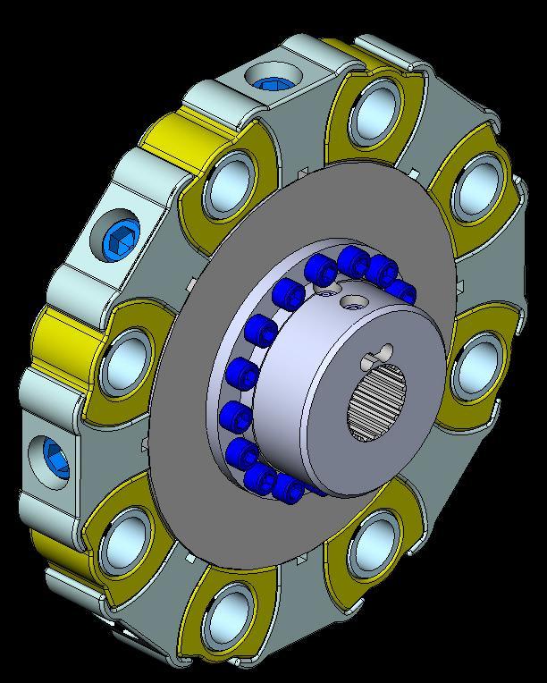
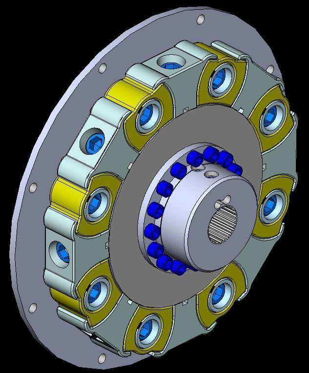
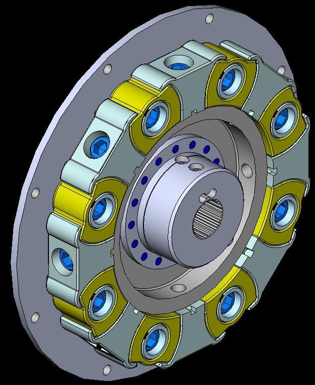
CENTAFLEX-H Assembly and operating instructions 008H /3000 M EN Rev
|
|
|
- Barbra Hunt
- 5 years ago
- Views:
Transcription


1 008H /
2 Contents 1 General remarks Safety Safety remarks Signal words Pictograms Qualification of deployed personnel Intended application Application not in compliance with the intended use Delivery, transport, storage and disposal Delivery Transport Storage Storage location Storage of couplings / flexible elements Disposal Technical description Characteristics Specifications Mounting General assembly instructions Mounting overview Mounting the adapter (9; design -3000) Preparing the pre-mounted assembly (C) for initial assembly Mounting the bushes (3) Mounting the hub (2) Mounting the hub (2) with cylindrical bore and keyway Mounting the hub (2) with CENTALOC clamping Mounting the pre-mounted assembly (C) Connecting the driving and the driven units After completed mounting Operation Operating faults, root causes and remedy...28 CENTA Antriebe Kirschey GmbH 2 / 35
3 7 Care and maintenance Work to be performed Cleaning the coupling Visual inspection of the coupling Visual inspection of the elastic element/-s Inspection of the screw connections Replacing defective parts Dismantling General dismantling instructions Separating the driving and the driven units Dismantling the elastic elements Dismantling the pre-mounted assembly (C) from the hub (2) Dismantling the hub (2; if necessary) Dismantling the hub (2) with cylindrical bore and keyway Dismantling the hub (2) with CENTALOC clamping Dismantling the bushes (3; if necessary) Dismantling the adapter (9; design -3000; if necessary) Reassembling the coupling Annex CENTA data sheet D (unlubricated screw connections) CENTA data sheet D (IP-screw connections) CENTA data sheet D Declaration of incorporation according to the EC Machinery Directive 2006/42/EC, Appendix II B...35 CENTA Antriebe Kirschey GmbH 3 / 35
4 Index of illustrations Fig. 5-1 Detail of the installation drawing title block Fig. 5-2 Mounting the adapter (9; design -3000) Fig. 5-3 Preparing the pre-mounted assembly (C) for initial assembly Fig. 5-4 Mounting the bushes (3) Fig. 5-5 Mounting the hub (2) with cylindrical bore and keyway Fig. 5-6 Mounting the hub (2) with CENTALOC clamping Fig. 5-7 Mounting the pre-mounted assembly (C) with drillings (v) to the hub (2) Fig. 5-8 Mounting the hub (2) to the pre-mounted assembly (C) with threads (s) Fig. 5-9 Connecting the driving and the driven units Fig. 8-1 Dismantling the elastic elements Index of tables Table 2-1 Shape and size of ventilation holes... 8 Table 5-1 Scope of supply of the design and chapters of mounting Table 5-2 Tightening torques for threaded pins Table 6-1 Troubleshooting table CENTA Antriebe Kirschey GmbH 4 / 35
5 1 General remarks These assembly and operating instructions form a constituent part of the coupling delivery and must be kept in an easily accessible place at all times. CENTA products are developed and produced to quality standard DIN EN ISO 9001:2000. In the interests of further development, CENTA reserves the right to make technical changes. IMPORTANT CENTA is unable to accept liability for damage and operating faults caused by failure to observe the operating instructions. These operating instructions are protected under copyright to CENTA Antriebe Kirschey GmbH. In case of technical questions, please enquire with our head office: CENTA Antriebe Kirschey GmbH Bergische Strasse Haan GERMANY Phone Fax centa@centa.de CENTA Antriebe Kirschey GmbH 5 / 35
6 2 Safety The purpose of these operating instructions is to enable users to: use the coupling safely and correctly maximize efficiency ensure that care and maintenance are carried out correctly For this reason, these operating instructions must be thoroughly read and understood prior to work on and with the coupling. WARNING Injury and material damage can occur as a result of: Failure to adhere to the safety and accident prevention regulations valid at the relevant installation site The safety and accident prevention regulations valid at the installation site in question must be adhered to when performing any of the tasks described in these operating instructions. 2.1 Safety remarks In these operating instructions, safety remarks are indicated by a pictogram and a signal word Signal words The following signal words are used in the safety remarks: DANGER Denotes the immediate threat of danger. If not prevented, fatal or extremely serious injuries can result. WARNING Denotes a potentially dangerous situation. If not prevented, fatal or extremely serious injuries can result. CAUTION Denotes a potentially dangerous situation. If not prevented, minor injuries and/damage to property may result. IMPORTANT Denotes application tips and particularly useful information. This is not a signal word denoting a dangerous or damaging situation. CENTA Antriebe Kirschey GmbH 6 / 35


7 2.1.2 Pictograms Possible pictograms in the safety precautions: Warning of a hazardous area Do not switch Use protective gloves Use protective goggles 2.2 Qualification of deployed personnel All the work described in these operating instructions may only be performed by authorized persons with adequate training and instruction. WARNING Injury and material damage can occur as a result of: Work at the coupling which is not described in these instructions Only carry out work which is described in these operating instructions. 2.3 Intended application WARNING Injury and material damage can occur as a result of: Application not in compliance with the intended use The couplings are intended exclusively for use in accordance with the relevant design. They may only be used under the specified conditions. CENTA Antriebe Kirschey GmbH 7 / 35
8 WARNING Injuries can occur as a result of: Contact with rotating parts Shield the coupling in accordance with the applicable accident prevention regulations with an enclosure. Exception: The coupling is encased by the driving and driven units. The scope of delivery provided by CENTA does not include a protective enclosure. This enclosure must fulfil the following criteria: Provide protection against persons gaining access to rotating parts Restrain any rotating parts which may be work loose Guarantee sufficient ventilation for the coupling This enclosure must be made of stable steel components. In order to ensure adequate ventilation for the coupling, the enclosure must be fitted with regular openings. For safety reasons, these openings must not exceed the dimensions outlined in table 2-1. Component Circular openings [mm] Rectangular openings [mm] Top of the enclosure Ø 8 8 Side elements of the enclosure Ø 8 8 Table 2-1 Shape and size of ventilation holes The enclosures must be positioned a minimum of 15 mm distant from rotating parts. The enclosure must be electrically conductive and be included in the equipotential bonding. Before commencing long-term operation, the plant must successfully complete a test run. CENTA Antriebe Kirschey GmbH 8 / 35
9 2.4 Application not in compliance with the intended use WARNING Injury and material damage can occur as a result of: Inadmissibly high torque Inadmissibly high or low speeds Exceeding the specified ambient temperature Inadmissible ambient medium Inadmissible coupling enclosure Exceeding the admissible overall misalignment values Only use the coupling for the specified application. CENTA bears no liability for damage resulting from application not in compliance with the intended use of the equipment. Should there be a change of plant parameters, the coupling design must be reviewed by CENTA (address see chapter 1). CENTA Antriebe Kirschey GmbH 9 / 35
10 3 Delivery, transport, storage and disposal 3.1 Delivery After delivery, the coupling: must be checked for completeness and correctness of the delivery. must be examined for possible transport damage (which must be reported immediately to the carrier). 3.2 Transport CAUTION Injury and material damage can occur as a result of: Incorrect transportation of couplings Ensure that the coupling is correctly transported. CAUTION Material damage to coupling components can occur as a result of: Contact with sharp-edged objects Protect coupling components for transportation. Only hoist coupling components with nylon belts or ropes. Always cushion parts when supporting them from below. Following transportation damage: Check the coupling carefully for damage. Consult the manufacturer (Address see chapter 1). 3.3 Storage CAUTION Material damage to elastic elements and rubber parts can occur as a result of: Incorrect storage These parts must be stored laid flat and so they cannot distort, and protected from ozone, heat, light, moisture and solvents. IMPORTANT Rubber parts are marked where possible with their production date. From this date, they may only be stored for a maximum of 5 years. CENTA Antriebe Kirschey GmbH 10 / 35
11 3.3.1 Storage location Requirements imposed on the storage location: Moderately ventilated and low in dust Dry (max. 65% humidity) Temperature stabilized (-10 C to +25 C) Free of ozone-producing devices such as light sources and electric motors Free of UV light sources and direct sunlight Do not store solvents and disinfectants, fuels or lubricants, acids, chemicals etc. in the same location For more details, refer to DIN Storage of couplings / flexible elements Unpack the parts. Check the packaging for damage. Replace if necessary. Check that the wax protection on steel components is intact. If necessary, patch or renew. Package the parts (for prolonged periods of storage, enclose desiccant and weld into film). Place the parts into storage. 3.4 Disposal RECYCLING Ensure safe, environmentally responsible disposal of operating supplies and exchange parts. For this, locally provided recycling facilities and regulations must be utilized. For disposal, the coupling parts must be separated where possible and sorted according to material type. CENTA Antriebe Kirschey GmbH 11 / 35
12 4 Technical description 4.1 Characteristics The coupling series offers the following advantages: High performance with compact dimensions. High torsional stiffnes, yet accomodation of minor misalignments and dampening of vibrations. High permissible rotational speeds. Extremely high thermal stability -50 to +150 C (-58 to +300 F) Oil resistant. Easy push in assembling. Free of axial forces. Free of wear hub-shaft screw clamping. Low maintenance. Noiseless. Cost efficient. 4.2 Specifications The specifications can be found in the catalogue and the dimensions in the installation drawing. CENTA Antriebe Kirschey GmbH 12 / 35
13 5 Mounting 5.1 General assembly instructions Any work method which impairs the safety of the coupling is prohibited. The user undertakes to notify the manufacturer immediately of any changes occurring at the coupling which could impair safety (address see chapter 1). WARNING Injuries can occur as a result of: Contact with rotating parts Before starting work at the coupling, switch off the plant and secure against unintentional start-up. WARNING Injury and material damage can occur as a result of: Assembly of the coupling in the wrong sequence Only ever assemble the coupling in the described sequence. WARNING Injury and material damage can occur as a result of: Falling coupling components Secure coupling components against falling to the floor. CAUTION Material damage to coupling components can occur as a result of: Contact with sharp-edged objects Protect coupling components for transportation. Only hoist coupling components with nylon belts or ropes. Always cushion parts when supporting them from below. CAUTION Material damage can occur as a result of: Soiled joint surfaces The surfaces that are to be joined must be free of dirt, preservatives and lubricants. CENTA Antriebe Kirschey GmbH 13 / 35
14 IMPORTANT Screw preparation and tightening torque levels for screws item(s) 8 in accordance with CENTA data sheet D (see chapter 9.1). Screw preparation and tightening torque levels for screws item(s) 4 in accordance with CENTA data sheet D (see chapter 9.2) The tightening torques for the threaded pins of hubs/flange hubs according to table 5-2 (see chapter 5.6.1). Use suitable lifting devices for assembly. Elements for connection of the coupling to customer components do not form part of the delivery. The following assembly stages are described for coupling 008H Part illustration and marking may different slightly from installation drawing and delivery state. IMPORTANT Use exclusively new screws supplied by CENTA. These are coated with microencapsulated adhesive INBUS PLUS IP which serves as a screw locking medium. IMPORTANT To ensure optimum screw locking, after tightening the curing time for the microencapsulated adhesive must be observed: Appr. 4-5 hours at room temperature (20 C) Higher temperatures will accelerate the curing time (e.g. 15 minutes at 70 C created by a hot air blower) After 24 hours, the adhesive is completely cured. CAUTION Injuries can occur as a result of: Hot coupling components Use suitable protective gloves. WARNING Injuries and material damages can occur by: Loosening adjustment screws (For fastening the hub/flange hubs) Lock adjustment screw with Loctite. CENTA Antriebe Kirschey GmbH 14 / 35
15 5.2 Mounting overview Mount the coupling as appropriate for the supplied design. These informations can be found in the title block of the installation drawing. They are explained below. Fig. 5-1 Detail of the installation drawing title block IMPORTANT This assembly instruction describes the mounting of several design. Mount the coupling as appropriate for the supplied design (see installation drawing). CENTA Antriebe Kirschey GmbH 15 / 35
16 Mount the coupling as appropriate for the supplied design. Take the supplied design as well as the built-in parts from the installation drawing. Scope of supply of the possible design, see following table. Design Scope of supply Mounting see chapter Pre-mounted assembly (C) Elastic element (1) Hub (2) Bush (3) Adapter assembly (7) Pre-mounted assembly (C) Elastic element (1) Hub (2) Bush (3) Hub (6) Adapter assembly (7) Adapter (9) Table 5-1 Scope of supply of the design and chapters of mounting CENTA Antriebe Kirschey GmbH 16 / 35
17 5.3 Mounting the adapter (9; design -3000) Fig. 5-2 Mounting the adapter (9; design -3000) Item Info Designation Remark 9 Adapter B Flywheel Customer part d Centring for bush Push the adapter (9) onto/into the centring of the flywheel (B). The centring for the bushes (d) must point towards the elastic elements. Screw the adapter (9) to the flywheel (B). CENTA Antriebe Kirschey GmbH 17 / 35
18 5.4 Preparing the pre-mounted assembly (C) for initial assembly Fig. 5-3 Preparing the pre-mounted assembly (C) for initial assembly Item Info Designation Remark 1 Elastic element 3 Bush 4 Screw ISO IP M.. If ordered 7 Adapter assembly Pre-mounted by CENTA C Pre-mounted assembly IMPORTANT The adapter assembly is delivered ready for installation. Do not dismantle any part. Push the bushes (3) and the screws (4; if ordered) out of the elastic element (1) and store temporarily. CENTA Antriebe Kirschey GmbH 18 / 35
19 5.5 Mounting the bushes (3) Fig. 5-4 Mounting the bushes (3) Item Info Designation Remark 3 Bush 4 Screw ISO IP M.. 9 Adapter B Flywheel Customer part d Centring for bush r Radius Push the bushes (3) into the centring for the bushes (d). Screw the bushes (3) to the adapter/flywheel (9/B; see installation drawing) using the screws (4). The radius (r) must point towards the elastic element (1). Screw preparation and tightening torque for the screws (4) see data sheet D , chapter 9.2. CENTA Antriebe Kirschey GmbH 19 / 35
20 5.6 Mounting the hub (2) Mount the hub (2) as appropriate for the supplied design (see installation drawing): Mounting the hub (2) with cylindrical bore and keyway, see chapter Mounting the hub (2) with CENTALOC clamping, see chapter Mounting the hub (2) with cylindrical bore and keyway Fig. 5-5 Mounting the hub (2) with cylindrical bore and keyway Item Info Designation Remark 2 Hub 27 Threaded pin See installation drawing A Shaft Customer part a b Face of shaft Face of hub CENTA Antriebe Kirschey GmbH 20 / 35
21 Unscrew the threaded pin/-s (27; if existing) out of the hub (2) and store temporarily. CAUTION Material damage can occur as a result of: Incorrect heating of the hubs/flange hubs Heat the hubs/flange hubs steadily in an oil bath, a fan oven, on an electric hot plate, either inductive or with a flame (ring burner). CAUTION Injuries can occur as a result of: Hot coupling components Use suitable protective gloves. Heat the hub (2) to a temperature of C. Push the hub (2) onto the shaft (A) with feather key. IMPORTANT The face of the shaft must not protrude to the face of the hub / flange hub. Otherwise the operation of the coupling is not guaranteed. Secure the hub (2) with the threaded pin/-s (27; if necessary). Threaded pin: size acc. the installation drawing tightening torque see table below. Threaded pin M6 M8 M10 M12 M14 M16 M20 Tightening torque [Nm] Table 5-2 Tightening torques for threaded pins CENTA Antriebe Kirschey GmbH 21 / 35
22 5.6.2 Mounting the hub (2) with CENTALOC clamping Fig. 5-6 Mounting the hub (2) with CENTALOC clamping Item Info Designation Remark 2 Hub 27 Threaded pin 29 Circlip DIN472 See installation drawing A Shaft Customer part e h j Shaft end Shaft shoulder Back side of circlip CENTA Antriebe Kirschey GmbH 22 / 35
23 Loosen the threaded pins (27). Push the hub (2) as appropriate for the supplied design with/without circlip (29; see installation drawing) onto the shaft (A): with circlip (29): Push the hub (2) onto the shaft (A), until the shaft end (e) touches the back side of the circlip (j). IMPORTANT Ensure that the hub/flange hub is correctly positioned on the shaft (against shaft end). If necessary brace hub with washer against the shaft. without circlip (29): Push the hub (2) onto the shaft (A) against the shaft shoulder (h). IMPORTANT Ensure that the hub/flange hub is correctly positioned on the shaft (against shaft shoulder). If necessary brace hub with washer against the shaft. Secure the hub (2) with the threaded pins (27). Threaded pin: size acc. the installation drawing tightening torque see table 5-2, chapter CENTA Antriebe Kirschey GmbH 23 / 35
24 5.7 Mounting the pre-mounted assembly (C) Fig. 5-7 Mounting the pre-mounted assembly (C) with drillings (v) to the hub (2) Fig. 5-8 Mounting the hub (2) to the pre-mounted assembly (C) with threads (s) CENTA Antriebe Kirschey GmbH 24 / 35
25 Item Info Designation Remark 2 Hub 8 Screw A Shaft Customer part C Pre-mounted assembly n p Contact surface inside Contact surface outside s Thread See installation drawing v Drilling See installation drawing IMPORTANT Ensure during installation that the pre-mounted assembly is in the right position. The right position can be found in the installation drawing. Otherwise, correct assembling of the coupling is not guaranteed. Mount the pre-mounted assembly (C) with drillings/threads (s/v; see installation drawing): Pre-mounted assembly (C) with drillings (v), see Fig. 5-7: Push the pre-mounted assembly (C) onto the centring of the hub (2). The contact surface inside (n; see installation drawing) must point towards the hub (2). Screw the pre-mounted assembly (C) to the hub (2) using the screws (8). Screw preparation and tightening torque for the screws (8) see data sheet D , chapter 9.1. Pre-mounted assembly (C) with threads (s), see Fig. 5-8: Push the pre-mounted assembly (C) onto the centring of the hub (2). The contact surface outside (p; see installation drawing) must point towards the hub (2). Screw the hub (2) to the pre-mounted assembly (C) using the screws (8). Screw preparation and tightening torque for the screws (8) see data sheet D , chapter 9.1. CENTA Antriebe Kirschey GmbH 25 / 35
26 5.8 Connecting the driving and the driven units Fig. 5-9 Connecting the driving and the driven units Item Info Designation Remark 3 Bush 9 Adapter See installation drawing B Flywheel Customer part C Pre-mounted assembly Turn the driving unit with the bushes (3) towards the driven unit with the pre-mounted assembly (C) until it is possible to push the bushes (3) into the pre-mounted assembly (C). Push together the driving unit with the bushes (3) and the driven unit with the pre-mounted assembly (C). Screw the driving and the driven unit according to the manufacturer's instructions. CAUTION Motor damage can occur as a result of: High axial forces at the axial bearings of the crank shaft Prior to commissioning the system, ensure that the crank shaft has axial play. CENTA Antriebe Kirschey GmbH 26 / 35
27 5.9 After completed mounting WARNING Injury and material damage can occur as a result of: Loose screw connections Before commissioning, the tightening torque levels of all screws must be checked and corrected if necessary. Before commencing long-term operation, the plant must successfully complete a test run. CENTA Antriebe Kirschey GmbH 27 / 35
28 6 Operation WARNING Injury and material damage can occur as a result of: Worn coupling components If the running noises change and/or vibrations occur turn the plant off immediately. Determine the fault and its root cause, and remedy. The troubleshooting process is simplified by the table in the next chapter. On principle in case of a fault, an analysis of the entire plant should be performed. 6.1 Operating faults, root causes and remedy In case of uncertainty or if you have questions, please contact our head office (address see chapter 1). Faults Possible root causes Remedy Running noises or vibrations in the plant Breakage of the elastic element/-s Tolerance error Loose bolts Tolerance error Damage due to rotary oscillation: Cylinder failure Inadmissibly high torque 1. Switch off the plant 2. Check the concentricity tolerances of the connections on the driving and driven units 3. Trial run 1. Switch off the plant 2. Check the tightening torques of the screws, correct if necessary 3. Trial run 1. Switch off the plant 2. Replace the elastic element/-s 3. Check the concentricity tolerances of the connections on the driving and driven units 4. Trial run 1. Switch off the plant 2. Replace the elastic element/-s 3. Trial run Table 6-1 Troubleshooting table CENTA Antriebe Kirschey GmbH 28 / 35
29 7 Care and maintenance WARNING Injuries can occur as a result of: Contact with rotating parts Before starting work at the coupling, switch off the plant and secure against unintentional start-up. The coupling requires low maintenance. We recommend a visual inspection at the regular scheduled maintenance intervals for the whole unit. 7.1 Work to be performed Cleaning the coupling Remove any loose dirt from the coupling Visual inspection of the coupling Inspect the coupling for cracks, chips or missing parts. Replace faulty and missing parts Visual inspection of the elastic element/-s IMPORTANT Exchange the elastic element/-s in the event of damage. Check the elastic element/-s for cracks Inspection of the screw connections Check the tightening torque levels of all screws and if necessary, correct. 7.2 Replacing defective parts Remove the coupling as described in chapter 8. Replace wearing parts. Mount the coupling as described in chapter 5. CENTA Antriebe Kirschey GmbH 29 / 35
30 8 Dismantling 8.1 General dismantling instructions Any work method which impairs the safety of the coupling is prohibited. The user undertakes to notify the manufacturer immediately of any changes occurring at the coupling which could impair safety (address see chapter 1). IMPORTANT This assembly instruction describes the dismantling of several design. Dismantle the coupling as appropriate for the supplied design (see installation drawing). The coupling is dismantled in reverse order to the assembly process. Please refer to the illustrations in chapter 5. Use suitable lifting devices for dismantling. WARNING Injuries can occur as a result of: Contact with rotating parts Before starting work at the coupling, switch off the plant and secure against unintentional start-up. WARNING Injury and material damage can occur as a result of: Dismantling of the coupling in the wrong sequence Only ever dismantle the coupling in the described sequence. WARNING Injury and material damage can occur as a result of: Falling coupling components Secure coupling components against falling to the floor. CAUTION Material damage to coupling components can occur as a result of: Contact with sharp-edged objects Protect coupling components for transportation. Only hoist coupling components with nylon belts or ropes. Always cushion parts when supporting them from below. CENTA Antriebe Kirschey GmbH 30 / 35
31 8.2 Separating the driving and the driven units See Fig. 5-9: Loosen and remove the screws of the connection of the driving and driven units. Pull the driving and driven units apart. 8.3 Dismantling the elastic elements Fig. 8-1 Dismantling the elastic elements Item Info Designation Remark 1 Elastic element 3 Bush 9 Adapter B Flywheel Customer part C Pre-mounted assembly Remove the elastic elements (1) out of the pre-mounted assembly (C). CENTA Antriebe Kirschey GmbH 31 / 35
32 8.4 Dismantling the pre-mounted assembly (C) from the hub (2) See Fig. 5-7 or 5-8: Loosen and remove the screws (8) of the connection pre-mounted assembly (C) and hub (2). Pull the pre-mounted assembly (C) off the centring of the hub (2) and remove. 8.5 Dismantling the hub (2; if necessary) Dismantle the hub (2) as appropriate for the supplied design (see installation drawing): Dismantling the hub (2) with cylindrical bore and keyway, see chapter Dismantling the hub (2) with CENTALOC clamping, see chapter Dismantling the hub (2) with cylindrical bore and keyway See Fig. 5-5: Loosen the threaded pin/-s (27; if existing) and remove off the hub (2). Remove the hub (2) from the shaft (A) Dismantling the hub (2) with CENTALOC clamping See Fig. 5-6: Loosen the threaded pins (27). Remove the hub (2) from the shaft (A). 8.6 Dismantling the bushes (3; if necessary) See Fig. 5-4: Loosen the screws (4) and remove with the bushes (3). 8.7 Dismantling the adapter (9; design -3000; if necessary) See Fig. 5-2: Loosen and remove the screws of the connection adapter (9) and flywheel (B). Pull the adapter (9) out of/off the centring of the flywheel (B) and remove. 8.8 Reassembling the coupling Reassemble the coupling as described in chapter 5. CENTA Antriebe Kirschey GmbH 32 / 35
33 9 Annex 9.1 CENTA data sheet D (unlubricated screw connections) Validity: For all non-dynamically stressed screw connections with not lubricated shank bolts in accordance with ISO 4014, ISO 4017 and ISO 4762 (DIN 912) with metric standard thread in accordance with DIN ISO 262, unless other specifications are given on CENTA documents. Preparation of parts that are to be screwed together: The joining areas must be free of dirt, preservatives and lubricants. Preparation of screws that ARE NOT secured with liquid screw locking medium: Use screws as delivered. Preparation of screws that ARE secured with liquid screw locking medium: Remove all grease from the thread. Screw tightening method: Screw in (by hand with torque wrench). CENTA Antriebe Kirschey GmbH 33 / 35
34 9.2 CENTA data sheet D (IP-screw connections) Validity: For all non-dynamically stressed screw connections with IP * -screws in accordance with ISO 4014, ISO 4017 and ISO 4762 (DIN 912) with metric standard thread in accordance with DIN ISO 262 and IP * -socket bolts with metric standard thread in accordance with DIN ISO 262, unless other specifications are given on CENTA documents. * The threads are coated with microencapsulated adhesive INBUS-PLUS (IP) which serves as a screw locking medium. Preparation of parts that are to be screwed together: The joining areas must be free of dirt, preservatives and lubricants. Preparation of IP-screws: Give the IP-screws extra lubrication with grease under the screw head. Screw tightening method: Screw in (by hand with torque wrench). Curing time for the microencapsulated adhesive: To ensure optimum screw locking, after tightening the curing time for the microencapsulated adhesive must be observed: Appr. 4-5 hours at room temperature (20 C) Higher temperatures will accelerate the curing time (e.g. 15 minutes at 70 C created by a hot air blower) After 24 hours, the adhesive is completely cured. CENTA Antriebe Kirschey GmbH 34 / 35
35 9.3 CENTA data sheet D Declaration of incorporation according to the EC Machinery Directive 2006/42/EC, Appendix II B Manufacturer: CENTA Antriebe Kirschey GmbH Bergische Strasse Haan / GERMANY Contact: Phone Fax centa@centa.de We herewith declare that the incomplete machine Product: Model / series code: Torsionally stiff coupling CF-H / 008H Installation size: Design: Serial number: all according to shipping documents, if applicable - provided this is possible as far as the scope of supply is concerned - complies with the following basic requirements of the Machinery Directive 2006/42/EC Appendix I, subchapters 1.1.2, 1.1.3, 1.1.5, 1.3.2, 1.3.3, and In addition, we declare that the special technical documents for this incomplete machine were compiled according to Appendix VII Part B and undertake to forward these to the market monitoring authorities by request via our "Documentation Department". Commissioning of the incomplete machine is interdicted until the incomplete machine has been incorporated in a machine and the latter complies with the provisions of the EC Machinery Directive and the EC Declaration of Conformity according to Appendix II A is on hand. The declaration is invalidated by every modification to the delivered parts. Authorised representative for the compilation of the relevant technical documents: by order of Gunnar Anderseck (Authorised Person Documentation) Declaration of incorporation was issued: Haan, by proxy Dipl.-Ing. Jochen Exner (Design Management) CENTA Antriebe Kirschey GmbH 35 / 35
CENTAX-TEST Assembly and operating instructions 053C GB3. M EN Rev. 1
 Assembly and operating instructions Contents 1 General remarks... 5 2 Safety... 6 2.1 Safety remarks... 6 2.1.1 Signal words... 6 2.1.2 Pictograms... 7 2.2 Qualification of deployed personnel... 7 2.3
CENTAFLEX-K Assembly and operating instructions 014K S... M EN Rev. 1
 Assembly and operating instructions Contents 1 General remarks... 5 2 Safety... 6 2.1 Qualification of deployed personnel... 6 2.2 Warning notes... 6 2.2.1 Signal words... 6 2.2.2 Symbols... 7 2.3 Application
CENTAX-SEC Series B Assembly and operating instructions CX BFS1-LE/SE-**-B M EN Rev. 1
 Assembly and operating instructions -**-B Contents 1 General remarks... 5 2 Safety... 6 2.1 Safety remarks... 6 2.1.1 Signal words... 6 2.1.2 Pictograms... 7 2.2 Qualification of deployed personnel...
TSCHAN - TORMAX VSG. Installation and Operation Manual TSCHAN Highly flexible shaft coupling BAWE 009-GBR-0 05/2004
 BAWE 009-GBR-0 05/2004 Installation and Operation Manual TSCHAN Highly flexible shaft coupling TSCHAN - TORMAX VSG TSCHAN GmbH Zweibruecker Strasse 104 D-66538 Neunkirchen-Saar Telephone: +49(0) 6821 866
FLENDER ZAPEX couplings. Type ZWT. Operating instructions BA 3505 EN 10/2011. FLENDER couplings
 FLENDER ZAPEX couplings Type ZWT Operating instructions FLENDER couplings FLENDER ZAPEX couplings Type ZWT Operating instructions Translation of the original operating instructions Technical data Notes
TSCHAN -B. Installation and Operation Manual TSCHAN Flexible Coupling BAWB 001-GBR-0 06/2004
 BAWB 001-GBR-0 06/2004 Installation and Operation Manual TSCHAN Flexible Coupling TSCHAN -B BH TSCHAN GmbH Zweibrücker Straße 104 D-66538 Neunkirchen-Saar Telefon: +49(0) 6821 866 0 Telefax: +49(0) 6821
Assembly and Maintenance Manual Type ASNU
 Assembly and Maintenance Manual Type ASNU Hatschekstr.36 69126 Heidelberg Germany Tel +49(0)6221 30470 Fax +49(0)6221 304731 info@stieber.de www.stieber.de Date of issue: 30.05.2018 GB Revision: 0 U:\EngUsers\!ProduktDoku\1AAA_Einbauerklaerung_Wartungsanleitung_Konformitaetserklaerung\1AAA_Wartungsanleitungen\Orginal_Worddatei\_ASNU.docx
Assembly and Maintenance Manual Type RSBW
 Assembly and Maintenance Manual Type RSBW Hatschekstr. 36 69126 Heidelberg Germany Tel +49(0)6221 30470 Tel +49(0)6221 304731 info@stieber.de www.stieber.de Stieber Clutch Date of issue: 16/03/2017 GB
Assembly and Maintenance Manual Type AS
 Assembly and Maintenance Manual Type AS Hatschekstr.36 69126 Heidelberg Germany Tel +49(0)6221 30470 Fax +49(0)6221 304731 info@stieber.de www.stieber.de Date of issue: 30.05.2018 GB Revision: 0 U:\EngUsers\!ProduktDoku\1AAA_Einbauerklaerung_Wartungsanleitung_Konformitaetserklaerung\1AAA_Wartungsanleitungen\Orginal_Worddatei\_AS.docx
HST -LS Interlocking device (Translation of Original Manual)
") Installation and Operating Manual for Components HST -LS Interlocking device (Translation of Original Manual) HST-LS Ident.-No.: 10268 HST-LS Ident.-No.: 10269 HST-LS, pictured Ident-Nr. 10269 The image
Installation and Operating Manual for Components HST -LS Interlocking device (Translation of Original Manual) HST-LS Ident.-No.: 10268 HST-LS Ident.-No.: 10269 HST-LS, pictured Ident-Nr. 10269 The image
BoWex FLE-PA. BoWex FLE-PAC. KTR-N Sheet: Edition: EN 1 of BoWex FLE-PA / FLE-PAC Operating/Assembly instructions
 1 of 17 is a torsionally rigid flange coupling. It is able to compensate for shaft misalignment, for example caused by manufacturing inaccuracies, thermal expansion, etc. BoWex FLE-PA BoWex FLE-PAC Drawn:
FLENDER BIPEX couplings. Types BWN, BWT and BNT. Operating instructions BA 3400 EN 01/2012. FLENDER couplings
 FLENDER BIPEX couplings Types BWN, BWT and BNT Operating instructions BA 34 EN 1/212 FLENDER couplings FLENDER BIPEX couplings Types BWN, BWT and BNT Operating instructions Translation of the original
Linear unit, pneumatic KHM 40
 Translation of original operating manual Linear unit, pneumatic KHM 40 Assembly and Operating Manual Superior Clamping and Gripping Imprint Imprint Copyright: This manual remains the copyrighted property
Adjustable Speaker Mount GRAVIS 12
 Adjustable Speaker Mount GRAVIS 12 User's Manual Translation of the original instructions Version 3.3 Released: 19.01.2017 Important Information, Please Read Before Use! KLING & FREITAG GmbH Junkersstraße
Adjustable Speaker Mount GRAVIS 8
 Adjustable Speaker Mount GRAVIS 8 User's Manual Translation of the original instructions Important Information, Please Read Before Use! KLING & FREITAG GmbH Junkersstraße 14 D-30179 Hannover TEL +49 (0)
Compensation unit AGE-XY 50-80
 Translation of the origninal manual Compensation unit AGE-XY 50-80 Assembly and operating manual Superior Clamping and Gripping Imprint Imprint Copyright: This manual remains the copyrighted property of
Turbocharger / VTR..0, VTR..1 Original assembly instructions English
 Assembly Instructions Turbocharger / VTR..0, VTR..1 Original assembly instructions English This document is valid for the VTR..0/..1 series: VTR160, VTR200, VTR250, VTR320, VTR400 VTR161, VTR201, VTR251,
RADEX -N Composite Operating/Assembly instructions
 1 of 14 RADEX -N is a torsionally stiff flexible steel lamina coupling. It is able to compensate for shaft misalignment, for example caused by thermal expansion, etc. note ISO 101. Drawn: 0.05.15 Kb/Wig
Installation and Operational Instructions for ROBATIC -clutch Types _.0 and _.0 Sizes 3 7
 Please read these Installation and Operational Instructions carefully and follow them accordingly! Ignoring these Instructions may lead to malfunction or to clutch failure, resulting in damage to other
These operating instructions apply for: NCX 380 NCZ 300 NCX 480 NCZ 370 NCX 580 L NCZ 480 NCX 660 K NCZ 560 NCZ 660 NCZ 800
 Original instructions Operating Instructions for May 2010 Electric Internal Vibrators BA No. 1092E Series NCX and NCZ These operating instructions apply for: NCX 380 NCZ 300 NCX 480 NCZ 370 NCX 580 L NCZ
Assembly and maintenance manual Type FSO, FSO-GR, FS, HPI
 Type FSO, FSO-GR, FS, HPI Hatschekstr.36 69126 Heidelberg Deutschland Tel +49(0)6221 30470 Fax +49(0)6221 304731 info@stieber.de www.stieber.de Date of issue: 23.08.2018 GB Revision: 0 U:\EngUsers\!ProduktDoku\1AAA_Einbauerklaerung_Wartungsanleitung_Konformitaetserklaerung\1AAA_Wartungsanleitungen\Orginal_Worddatei\M1124E_0_FSO_FSO-GR_FS_HPI.docx
Turbocharger / A100-L Original assembly instructions English
 Assembly Instructions Turbocharger / A100-L Original assembly instructions English This document is valid for the A100-L series: A165-L, A170-L, A175-L, A180-L, A185-L, A190-L Purpose The assembly instructions
Installation and operating instructions for elastic jaw coupling REK DCO. E e. Schaberweg Telephone
 elastic jaw coupling REK DCO E 06.696e Schaberweg 30-38 Telephone +49 6172 275 0 61348 Bad Homburg Fax +49 6172 275 275 Germany www.ringspann.com info@ringspann.com Page: 2 Important Before installation
Rotary feed-through DDF-S/-KS
 Translation of the Original Operating Manual Rotary feed-through DDF-S/-KS Assembly and Operating Manual Superior Clamping and Gripping Imprint Imprint Copyright: This manual remains the copyrighted property
Swiveling gripper finger GFS 16-40
 Translation of the original manual Swiveling gripper finger GFS 16-40 Assembly and Operating Manual Superior Clamping and Gripping Imprint Imprint Copyright: This manual remains the copyrighted property
Please read and observe
 Please read and observe these operating instructions carefully! Non-observation of the information it contains may lead to coupling malfunction or failure and consequential damage. Danger and information
Small gripper with large stroke KGG
 Translation of the original manual Small gripper with large stroke KGG 220-280 Assembly and Operating Manual Superior Clamping and Gripping Imprint Imprint Copyright: This manual remains the copyrighted
FLENDER ARPEX Plate packs with close-fitting bolt connection. ARW-4 Sizes to Assembly instructions An 4239 en 12/2015.
 FLENDER ARPEX Plate packs with close-fitting bolt connection ARW-4 Sizes 101-4 to 292-4 Assembly instructions FLENDER couplings FLENDER ARPEX Plate packs with close-fitting bolt connection ARW-4 Sizes
Operating / Assembly Instructions Type A and CS Coupling
 Page: 1 of 14 Subject Index 1. Technical Data 2. Hints 2.1. General Hints 2.2. Warning and Safety Hints. 2.3. General Hints to Danger. 2.4. Proper use. 3. Storage. 4. Assembly. 4.1. Coupling components.
RINGFEDER POWER TRANSMISSION GMBH Werner-Heisenberg-Straße 18, D Groß-Umstadt, Germany Phone: +49 (0) Fax: +49 (0)
 Fax: +49 (0)") Installation and Operation Manual Installation and Operation Manual TSCHAN Flexible Flexible Coupling Coupling BAWS 005-GBR-1 01/2012 TSCHAN -S S-BT, S-BS RINGFEDER POWER TRANSMISSION GMBH Werner-Heisenberg-Straße
Installation and Operation Manual Installation and Operation Manual TSCHAN Flexible Flexible Coupling Coupling BAWS 005-GBR-1 01/2012 TSCHAN -S S-BT, S-BS RINGFEDER POWER TRANSMISSION GMBH Werner-Heisenberg-Straße
SERVO MOTORS BRUSHLESS SERVO MOTORS OPERATING INSTRUCTIONS 2016
 SERVO MOTORS BRUSHLESS SERVO MOTORS OPERATING INSTRUCTIONS 2016 3009/16 en Ed.02.2016 Read these Operating Instructions before performing any transportation, installation, commissioning, maintenance or
General operating manual for assembly, commissioning and maintenance of valves and hydraulic manifolds
 for assembly, commissioning and maintenance of valves and hydraulic manifolds 110210_general_operating_manual 07.2018 Table of contents Contents Page Important information 2 Important safety instructions
Installation and Operational Instructions for ROBA -D Couplings Type 91_. _
 Please read the Installation and Operational Instructions carefully and follow them accordingly! Ignoring these Instructions may lead to malfunctions or to coupling failure, resulting in damage to other
Installation and Operating Instructions for ROBA -ES couplings Type 940. _. _ Sizes 14-48
 Table of contents: Please read and observe this Operating Instruction carefully. A possible malfunction or failure of the clutch and damage may be caused by not observing it. Page 1: - Table of contents
Nor-Mex G. Assembly and operating instructions TSCHAN Elastic coupling BAWN 002-GBR-1 10/2008
 BAWN 002-GBR-1 10/2008 Assembly and operating instructions TSCHAN Elastic coupling Nor-Mex G TSCHAN GmbH Zweibrücker Straße 104 D-66538 Neunkirchen-Saar Telefon: +49(0) 6821 866 0 Telefax: +49(0) 6821
ROTEX Operating/Assembly instructions Type AFN-SB spec. ROTEX
 0223 EN 1 of 13 Torsionally flexible jaw-type couplings AFN-SB spec. and their combinations for finish bored, pilot bored and unbored couplings 0223 EN 2 of 13 is a torsionally flexible jaw coupling. It
Turbocharger / TPS-H Original assembly instructions English
 Assembly Instructions Turbocharger / TPS-H Original assembly instructions English This document is valid for the TPS-H series: TPS44-H, TPS48-H, TPS52-H Purpose TPS-H turbocharger The assembly instructions
Type AB with limitation of axial backlash
 1 of 21 with limitation of axial backlash Flexible pin & bush couplings types KX and KX-D and their combinations Type KX - AB (taper pin design B) Type KX-D - AB (taper pin design B) 2 of 21 is a torsionally
Type Operating Instructions. Bedienungsanleitung Manuel d utilisation
 Globe control valve, pneumatically operated Actuator sizes 40 mm - 125 mm, Nominal diameter DN10-65 Kolbengesteuertes Geradsitzventil Antriebsgrößen 40 mm - 125 mm, Nennweiten DN10-65 Vanne à siège droit
PLS / WPLS / PLV / PLS-HP / PLF-HP PLN / WPLN / WGN / PLFN PSN / PSFN PLE / WPLE / PLFE PLPE / WPLPE / PLHE
 Instruction Manual Standard Planetary Gearbox PLS / WPLS / PLV / PLS-HP / PLF-HP PLN / WPLN / WGN / PLFN PSN / PSFN PLE / WPLE / PLFE PLPE / WPLPE / PLHE GB_ 100225283 / Rev. Stand 004 www.zetek.ru +7(495)
Assembly Instructions
 Drive Technology \ Drive Automation \ System Integration \ Services *2450452_0617* Assembly Instructions Didactics - Gear Unit Technology Helical Gear Unit R57F AD2 Edition 06/2017 2450452/EN SEW-EURODRIVE
FLENDER UZWN overrunning clutches with FLENDER KSUN clutch shift. Types UZWN and KSUN. Operating instructions BA 3001 en 06/2012.
 FLENDER UZWN overrunning clutches with FLENDER KSUN clutch shift Types UZWN and KSUN Operating instructions FLENDER couplings FLENDER UZWN overrunning clutches with FLENDER KSUN clutch shift Types UZWN
RINGFEDER POWER TRANSMISSION GMBH Werner-Heisenberg-Straße 18, D Groß-Umstadt, Germany Phone: +49 (0) Fax: +49 (0)
 Fax: +49 (0)") Installation and Operation Manual Flexible Coupling Installation and Operation Manual TSCHAN Flexible Coupling TSCHAN -B BH BAWB 001 -GBR-1 03/2010 RINGFEDER POWER TRANSMISSION GMBH Werner-Heisenberg-Straße
Installation and Operation Manual Flexible Coupling Installation and Operation Manual TSCHAN Flexible Coupling TSCHAN -B BH BAWB 001 -GBR-1 03/2010 RINGFEDER POWER TRANSMISSION GMBH Werner-Heisenberg-Straße
Instructions for Fitting, Operating and Maintenance Canopy Door RE / (St.: )
") EN Instructions for Fitting, Operating and Maintenance Canopy Door 1 818 012 RE / (St.: 12.2010) 12.2010 ENGLISH Contents 1 Safety Instructions... 3 1.1 Qualified persons... 3 1.2 Symbols and signal words
EN Instructions for Fitting, Operating and Maintenance Canopy Door 1 818 012 RE / (St.: 12.2010) 12.2010 ENGLISH Contents 1 Safety Instructions... 3 1.1 Qualified persons... 3 1.2 Symbols and signal words
FLENDER COUPLINGS SIPEX. Operating Instructions 3800en Edition 10/2017 SNN, SGG, SGG-A, SHH, SKK, SII, SGS, SHH-W
 FLENDER COUPLINGS SIPEX Operating Instructions 3800en Edition 10/2017 SNN, SGG, SGG-A, SHH, SKK, SII, SGS, SHH-W 26.09.2017 09:25 V2.01 Introduction 1 Safety instructions 2 FLENDER COUPLINGS SIPEX 3800en
Installation and Operating Instructions for ROBA-stop -Positioning Brake Type 80_.41_._ Sizes 3 11
 Please read and observe this Operating Instruction carefully! A possible malfunction or failure of the brake and any damage may be caused by not observing it. Table of contents: Page 1: Page 2: Page 3:
MULTI CROSS RILLO. Highly flexible tyre coupling with taper bushings
 MULTI CROSS RILLO Highly flexible tyre coupling with taper bushings Maschinenfabrik Dipl.-Ing. Herwarth Reich GmbH Vierhausstr. 53 D-44807 Bochum P.O. Box 10 20 66 D-44720 Bochum Tel.: +49 / (0)234 / 959
Pneumatic Swivel Unit SRU 20-60
 Translation of the original manual Pneumatic Swivel Unit SRU 20-60 Assembly and operation manual Superior Clamping and Gripping Imprint Imprint Copyright: This manual remains the copyrighted property of
Installation and Operational Instructions for ROBATIC -clutch Type and Type Sizes 3 9
 Please read the Operational Instructions carefully and follow them accordingly! Ignoring these Instructions may lead to malfunctions or to clutch failure, resulting in damage to other parts. Contents:
Installation and Operating Instructions for EAS -NC clutch Type 45_. _. _ Sizes 02 and 03
 Table of contents: Please read and observe this Operating Instruction carefully! A possible malfunction or failure of the clutch and any damage may be caused by not observing it. Page 1: - Table of contents
Pneumatic rotary actuator SRH-plus 20-60
 Translation of the Original operating manual Pneumatic rotary actuator SRH-plus 20-60 Assembly and Operating Manual Superior Clamping and Gripping Imprint Imprint Copyright: This manual remains the copyrighted
BA EN.=A. Ä.=A.ä. Operating Instructions. Gearbox. Type 12. / 52.
 BA 12.0028 EN.=A. Ä.=A.ä Operating Instructions Gearbox Type 12. / 52. Product key Gearboxes 1 2... Product group Product family Gearbox size Design Geared motors 1 2... Product group Product family Gearbox
Installation and Operating Instructions Electric Vibrators HV/VFL Series
 Installation and Operating Instructions Electric Vibrators HV/VFL Series Original Instruction Würges Vibrationstechnik GmbH Daimlerstraße 9 D-86356 Neusäß Telephone +49 821 463081 Telefax +49 821 463084
Operating Instructions
 Operating Instructions Ex UPS Combination of > 8265/5 GUBox control panel > 8316 battery box Contents 1 Contents 1 Contents 2 2 General Information 2 3 Safety Instructions 2 4 Conformity to standards 3
Mounting and Operating Instructions EB 8111/8112 EN. Series V2001 Valves Type 3321 Globe Valve
 Series V2001 Valves Type 3321 Globe Valve Type 3321 Globe Valve with rod-type yoke and Type 3372 Electropneumatic Actuator (350 cm²) Mounting and Operating Instructions EB 8111/8112 EN Edition June 2013
Product Information Overspeed governor GB 260
 Product Information GB 260 Copyright as per DIN ISO 16016. Manufactured under licence of C. Haushahn GmbH & Co. I Subject to modification. Published by SLC Sautter Lift Components GmbH & Co. KG Borsigstrasse
2-finger angular gripper PWG
 Original operating manual 2-finger angular gripper PWG 65-230 Assembly and operating manual Superior Clamping and Gripping Imprint Imprint Copyright: This manual remains the copyrighted property of SCHUNK
Turbocharger / TPL-B Original assembly instructions English
 Assembly Instructions Turbocharger / TPL-B Original assembly instructions English This document is valid for the TPL-B series: TPL85-B14/15/16, TPL91-B Purpose The assembly instructions explain how the
Spare parts list Return line filter RFM with 2-hole attachment
 Spare parts list Return line filter with 2-hole attachment Tank-top mounted version: up to 200 l/min, up to 10 bar 75 90 150 165 185 195 1. MAINTENANCE 1.1 GENERAL Please follow the maintenance instructions!
Spare Parts List Tank-Top Return Line Filter RFN with Elements to DIN up to 630 l/min, up to 10 bar
 Spare Parts List Tank-Top Return Line Filter RFN with Elements to DIN 24550 up to 630 l/min, up to 10 bar RFN 40 RFN 63 RFN 100 RFN 160 RFN 250 RFN 400 RFN 630 1. MAINTENANCE 1.1 GENERAL Please follow
Operating instructions Accu Jet
 Operating instructions Accu Jet Keep for future use! Ident number: 04.8800.000 Air Line Table of contents 1 Scope of delivery... 4 2 Operator instructions... 5 3 Safety... 6 3.1 Intended use...8 4 Description
Installation and Operating Instructions Magnetic Vibrator MR 1
 Installation and Operating Instructions Magnetic Vibrator MR 1 (Translation of the Original Instruction Manual) Würges Vibrationstechnik GmbH Daimlerstraße 9 D-86356 Neusäß Telephone +49 821 999824-00
KeContact P20. User manual
 KeContact P20 User manual Comments to this manual In this manual you will find warnings against possible dangerous situations. The used symbols apply to the following meanings:!! WARNING! Indicates a potentially
Installation and Operational Instructions for EAS -Compact overload clutch, Type 49_. 4._ Sizes 4 and 5
 Please read these Operational Instructions carefully and follow them accordingly! Ignoring these Instructions may lead to malfunctions or to clutch failure, resulting in damage to other parts. Contents:
Operating Guide SBFV (PN16/25) ENGLISH Steel butterfly valve SBFV Page 2. Danfoss VI.IX.A1.02 1
 ENGLISH Steel butterfly valve SBFV Page 2. Danfoss VI.IX.A1.02 1") Operating Guide SBFV (PN16/25) ENGLISH Steel butterfly valve SBFV www.danfoss.com Page 2 Danfoss 2016.06 VI.IX.A1.02 1 Table of Contents: 1. OVERVIEW... 3 2. GENERAL... 3 2.1 Safety...3 2.2 Proper use...4
Operating Guide SBFV (PN16/25) ENGLISH Steel butterfly valve SBFV www.danfoss.com Page 2 Danfoss 2016.06 VI.IX.A1.02 1 Table of Contents: 1. OVERVIEW... 3 2. GENERAL... 3 2.1 Safety...3 2.2 Proper use...4
Operating manual. Custom made gearboxes
 Operating manual Custom made gearboxes DSS-Nr. 100389549 DSS-Rev. 001 Datum 16.01.2018 Contents Contents 1 General information 3 1.1 Using the operating manual 3 1.2 Warnings in this operating manual 4
Sealed Angle Gripper DWG 44-80
 Translation of the original manual Sealed Angle Gripper DWG 44-80 Assembly and Operating Manual Superior Clamping and Gripping Imprint Imprint Copyright: This manual remains the copyrighted property of
Sediment strainer (Type Y)
") Installation,Operation and Maintenance Manual Serial No. H-V034-E-9 Sediment strainer (Type Y) Contents (1) Be sure to read the following warranty clauses of our product 1 User s Manual (2) General operating
Installation,Operation and Maintenance Manual Serial No. H-V034-E-9 Sediment strainer (Type Y) Contents (1) Be sure to read the following warranty clauses of our product 1 User s Manual (2) General operating
A company of ThyssenKrupp Elevator. ThyssenKrupp Aufzugswerke. Operating Manual. Oil buffer
 A company of ThyssenKrupp Elevator ThyssenKrupp Aufzugswerke Operating Manual Oil buffer OPERATING MANUAL Printer s imprint All rights reserved. Copyright by: THYSSENKRUPP AUFZUGSWERKE GMBH P.O. box 23
Ex m Solenoid Operator Type 0519
 nass magnet GmbH Eckenerstrasse 4-6 D-30179 Hannover Doc. No. 113-720-0002 Revision No. 2 01.06.2015 Ex m Solenoid Operator Type 0519 Operating Instructions Dear Customer! To ensure the function and for
D58 Series Brake Instructions
 D58 Series Brake Instructions 4740 W. Electric Avenue Milwaukee, WI 53219 414/672-7830 FAX 414/672-5354 www. dingsbrakes.com Safety information 2 Safety information 2.1 Persons responsible for the safety
Operation manual Flexible pin type coupling according to KWN 22014
 Operation manual Flexible pin type coupling according to KWN 22014 Author: Dipl.-Ing.. V. Hausdorf 24.01.2005 gez. V. Hausdorf Approved: Dr.-Ing. Ch. Spensberger 24.01.2005 gez. Dr.-Ing. Ch. Spensberger
BWN, BWT, BNT. Operating Instructions. FLENDER couplings BIPEX. 3400en. Edition 03/2017.
 BWN, BWT, BNT Operating Instructions FLENDER couplings BIPEX 3400en Edition 03/2017 www.siemens.com/drives 30.03.2017 13:11 V5.02 Introduction 1 Safety instructions 2 BIPEX FLENDER couplings 3400en Operating
Original Operating Manual
 matev GmbH Nürnberger Str. 50 90579 Langenzenn T +49 (0) 9101 9087-0 F +49 (0) 9101 9087-20 info@matev.eu www.matev.eu Original Operating Manual Snow blade SRM-FB 120 CD Angle adjustment mechanical Version
Operating Instruction
 Operating Instruction Drive element LEWA - ecosmart type LCA with manual stroke adjustment, motor mounted vertically Table of contents 1 General information / safety 1.1 Important preliminary information
Assembly Instructions
 Drive Technology \ Drive Automation \ System Integration \ Services *21279799_071* Assembly Instructions Didactics Gear Unit Technology Helical Gear Unit R57F AD2 Edition 07/201 21279799 / EN SEW-EURODRIVE
Type Operating Instructions. Bedienungsanleitung Manuel d utilisation
 2/2-way angle seat control valve 2/2-Wege-Schrägsitzregelventil Vanne de réglage à siège incliné 2/2 voies Operating Instructions Bedienungsanleitung Manuel d utilisation We reserve the right to make technical
Original Operating Manual
 2010-10-29 Original Operating Manual Control Panel Comfort for Pedelecs Series 4313 Save for future use! Marquardt GmbH Schlossstraße 16 78604 Rietheim-Weilheim E-mail: marquardt@marquardt.de Website:
Pressure relief valve
 Pressure relief valve Operating manual Series DHV 712 Version BA-2015.10.20 EN Print-No. 300 510 TR MA DE Rev001 ASV Stübbe GmbH & Co. KG Hollwieser Straße 5 32602 Vlotho Germany Phone: +49 (0) 5733-799-0
Installation and Operational Instructions for EAS - HTL housed overload clutch Sizes 01 3 Type 490._24.0
 Please read these Operational Instructions carefully and follow them accordingly! Ignoring these Instructions may lead to malfunctions or to clutch failure, resulting in damage to other parts. Contents:
CENTAMAX -B. Torsionally soft couplings with precompression for independently mounted units on rigid or soft mounts. Catalog CM-B-E-06-04
 Torsionally soft couplings with precompression for independently mounted units on rigid or soft mounts Catalog CM-B-E-06-04 Power Transmission Leading by innovation For many years we have been supplying
These installation and maintenance instructions must be read in full and completely understood before the installation!
 These installation and maintenance instructions must be read in full and completely understood before the installation! 1. General information on the installation and maintenance instructions These instructions
Original Operating Manual
 matev GmbH Nürnberger Str. 50 90579 Langenzenn T +49 (0) 9101 9087-0 F +49 (0) 9101 9087-20 info@matev.eu www.matev.eu Original Operating Manual Front Power System und Front PTO shaft FPS- JD X 950 R for
Accessories for Wind Power Inverter WINDY BOY PROTECTION BOX 400 / 500 / 600
 Accessories for Wind Power Inverter WINDY BOY PROTECTION BOX 400 / 500 / 600 Installation Guide WBP-Box-IEN103320 IMEN-WBP-BOX Version 2.0 EN SMA Solar Technology AG Table of Contents Table of Contents
FLENDER ARPEX plate packs with conical bolting. ARP Size Assembly instructions AN 4256 en 07/2016. FLENDER couplings
 FLENDER ARPEX plate packs with conical bolting ARP Size 325-6 Assembly instructions FLENDER couplings FLENDER ARPEX plate packs with conical bolting ARP Size 325-6 Assembly instructions Translation of
Installation, Operating and Maintenance Instructions Retractable Door / Art.-Nr.:
 Installation, Operating and Maintenance Instructions Retractable Door 06.2008 / Art.-Nr.: 1 818 024 ENGLISH CONTENTS PAGE 1 SAFETY REQUIREMENTS 3 1.1 Symbols and key words used 3 1.2 Designated use 3 1.3
Planar surface gantry EXCM-30. Instructions. Mechanical installation b [ ]
![Planar surface gantry EXCM-30. Instructions. Mechanical installation b [ ]](/thumbs/91/106333591.jpg "Planar surface gantry EXCM-30. Instructions. Mechanical installation b [ ]") Planar surface gantry EXCM-30 Instructions Mechanical installation 804447 605b [8044434] EXCM-30 Translation of the original instructions LOCTITE is a registered trademark of its respective trademark holder
Planar surface gantry EXCM-30 Instructions Mechanical installation 804447 605b [8044434] EXCM-30 Translation of the original instructions LOCTITE is a registered trademark of its respective trademark holder
Contents H-V034-E-12. Serial No. (page) (1) Be sure to read the following warranty clauses of our product 1. (2) General operating instructions 2
 (1) Be sure to read the following warranty clauses of our product 1. (2) General operating instructions 2") Serial No. H-V034-E-12 Sediment strainer (Type Y) Contents (page) (1) Be sure to read the following warranty clauses of our product 1 User s Manual (2) General operating instructions 2 (3) General instructions
Serial No. H-V034-E-12 Sediment strainer (Type Y) Contents (page) (1) Be sure to read the following warranty clauses of our product 1 User s Manual (2) General operating instructions 2 (3) General instructions
Operating Instructions
 Operating Instructions Table of contents Table of contents... 1 1. Declaration... 1 2. Warranty and liability... 2 3. Gear description... 2 4. Gear types... 2 5. Safety... 3 5.1 General safety information...
Declaration of Conformity as per Directive 97/23/EC
 Declaration of Conformity as per Directive 97/23/EC The manufacturer declares that:, 47906 Kempen, Germany PTFE-lined Rotary plug valves Series 23e, with packing with lever for 90 operation with worm gear
2-finger parallel gripper GM
 Translation of the Original operating manual 2-finger parallel gripper GM 80-201 Assembly and Operating Manual Superior Clamping and Gripping Imprint Imprint Copyright: This manual remains the copyrighted
Instruction Manual. Unique 7000 Series Aseptic - Manually Operated ESE02421-ENUS Original manual
 Instruction Manual Unique 7000 Series Aseptic - Manually Operated 2210-0042 ESE02421-ENUS1 2013-03 Original manual Table of contents The information herein is correct at the time of issue but may be subject
SP + The New Generation. MF Version (oil-lubricated) Operating manual and information on explosion protection. for use in area with explosion hazards
 Operating manual and information on explosion protection. for use in area with explosion hazards") SP + The New Generation MF Version (oil-lubricated) for use in area with explosion hazards Operating manual and information on explosion protection MOTOR TECHNOLOGY LTD MOTEC HOUSE, CHADKIRK BUSINESS PARK,
SP + The New Generation MF Version (oil-lubricated) for use in area with explosion hazards Operating manual and information on explosion protection MOTOR TECHNOLOGY LTD MOTEC HOUSE, CHADKIRK BUSINESS PARK,
Installation and Operating Instructions for RIMOSTAT -Friction Torque Limiter RSHD E e
 RIMOSTAT -Friction Torque Limiter e Schaberweg 30-38 Phone +49 6172 275-0 61348 Bad Homburg Fax +49 6172 275-275 Germany www.ringspann.com info@ringspann.com Issue: 02.11.2016 Version: 4 Drawn: RUPD Checked:
Operation Manual Flexible Claw couplings according to KWN 22013
 Operation Manual Flexible Claw couplings according to KWN 22013 Author: Dipl.-Ing.. V. Hausdorf 19.02.2007 gez. V. Hausdorf Approved: Dipl.-Ing. H. Neugebauer 19.02.2007 gez. H. Neugebauer Name Date Signature
alpha Advanced Line SP + / SK + / SPK + / SC + / SPC + / HG +
 alpha Advanced Line SP + / SK + / SPK + / SC + / SPC + / HG + Operating Manual 2022-D062611 Revision: 01 Customer Service department WITTENSTEIN alpha GmbH Customer Service Walter-Wittenstein-Straße 1
Installation and Operating Instruction for Brake Caliper HW 150 HFA and HW 180 HFA E e
 Installation and Operating Instruction for Brake Caliper HW 150 HFA and HW 180 HFA E 09.736e Schaberweg 30-38 Phone +49 6172 275-0 61348 Bad Homburg Fax +49 6172 275-275 Germany www.ringspann.com info@ringspann.com
Operating Instructions. Globoidal cam gear
 Operating Instructions Globoidal cam gear Type : Serial No. : TABLE OF CONTENTS 1. General 1.1 Validity 1.2 Safety instructions 1.3 Shipment 1.4 Transport Regulations 1.5 Weights of gear types 2. Instructions
Manufacturer s Declaration as per EU-Directives Page 1 of 2
 The manufacturer Manufacturer s Declaration as per EU-Directives Page 1 of 2 BRAY Armaturen & Antriebe Europa, D47807 Krefeld for Butterfly valves all Series 2[.].& Series 3[.] : Series 20/21 (2 body-halves
ROTEX SD shiftable jaw coupling
 1 of 16 SD shiftable jaw coupling Drawn: 201-08-31 Pz Replacing: dated 2006-08-14 Verified: 201-09-07 Pz Replaced by: 2 of 16 SD is a torsionally flexible jaw coupling shiftable at standstill. It is able