INSTRUCTIONS. Switchgear WITH STORED ENERGY OPERATOR AIR MAGNETIC CIRCUIT BREAKERS. TYPES MA-75C1, MA-250C1 AND MA-350C1, 5-kV.
|
|
|
- Ambrose Jefferson
- 5 years ago
- Views:
Transcription
1 Switchgear INSTRUCTIONS TYPES MA-75C1, MA-250C1 AND MA-350C1, 5-kV AIR MAGNETIC CIRCUIT BREAKERS WITH STORED ENERGY OPERATOR TYPE 515:l 18x April, 1978.
2 TABLE OF CONTENTS INTRODUCTION... 1 ADJUSTMENTS Wurrnty... 1 Circult Brrrkrr Tina...; Roaiwng... 1 Rhsrm Brrriar AicmMy Stor TiltingArcChutsl Circuit Brmabr Pnparaiion... 1 tkrrirr Stwks Conuct Pmruro of Dirconnoct Arm Hinge hint Arcing Cootact Hin~ Joint. CIRCUIT. BREA$ER DESCRIPTION Contact Allmnt rnd Rrplrrmmt Arc Intonliption......; Auxiliuy Switdr 0'~mton Intarlock Plungrr S t b Emr~ Operator Trip btch Adjratmonts Trio Lnch Chock SwiM kianbd Chrrglng of Closing spring RdosingContrd Mainmum Slow Clan Auriliry Equipmmfot i Removd of Spdng Blocking (kviu AuJli Sluluh Rwnl of am Sprinw C.#eltorTripDwiw Motor Cutoff Wtch Tripsohdd ~ocor cutoff Swicd, Adjurmunt Arc Chum Aumbly Clom lach Elm Mlu8~n1 CIRCUIT BREAKER OPERATION ~(orr Latch QuClr etch Adj&t ~ rhright n Mjw-t STORE0 ENERGY OPERATOR OESCRlPTlON OF OPERATION 6 Spring W n g Cyclm... 6 lbddn@bnud...: Qoringw e... ;... 7 ~prin~ ~mchrgl AW adng... 7 ~rbpil&l CVb ~twwj ~pmtw compomna ~ormnc~atun EkeukJhtml... Sdng Chrging ao8&bgclmllt... 9 los so brch - )Jlrch.nlal... rnd Ekctrlcml Intorlocks -9 9 Trip Adjramwnt...; OnrtrmI Intatlack adng htch M uhid. MAINTENANCE AND T ESI'INQ Gmrrl... to "AsFound"T a& R ~ lnunc~ond C Maintanante luuiwhl- Staqd Enow O#neor Lubrlutlon *ASL.~~-TUU... n. Fiq. 1 Circuit Bnalur Hndling Instructions Fig 12 Trip l.dr Blm 8nd UIU~ Sm'tch Mjmrmnts F lg. 2 Typicd Cirwlt Brukr AuMnblicn Fig. 13 Maintanma Clou Sprlno Blockln0.hvia lnartlon F& Stad En- OPIrator - L+(. VIaw F1 g. 14 Motor Cutoff Switch... i.37 Fi q. 4 Slquna of Opvnlan Fig. 15 Clem La* BIm and Chock Swkd Adju~tm~u Fie 6 Ty pa 0-10 Auxiliwy Swltch Fig. 16 Clmlng Shg Oirch.rp Modwlun Fie 6 kc CkuW Fig. 17 Clou tt& Mochuriul Intorlock'... i40 Fig S t d Enrroy Owator R.H. Vii Fig. 18 Lubrication Points on F m ud Opmtm. Fig 8 61St Stod O#~W - Fmnt Vim Orl~kuRlblyrdUnlupAtrmbl~ L!lkknkn bnvd Sehwn for hord E~rw Owrator Fig 19 Lubrication Points on Braakor Fig. 10 Stud nd Supp~ Fig. LubLubriution Chut, Fig.11 TdplrtchCkwwAdjurmwnt Fib21 CircuitBndurWd, &cchutasuppo~inplrr... 44
3 ... INTRODUCTION Operation Book This instruction manual contains installation, operation and maintenance information for Types MA-75C1. MA-250C1 and MA-350C1 stored energy operated, 5 - k air ~ magnetic circuit breakers. WARRANTY. The sales contract carries all information on warranty coverage. RECEIVING Circuit breakers are shipped from the factory completely assembled. Observe weight morkings on crates and ensure that capable handling equipment is used. Remove crating carefully with the correct tools. Check each item with the hipping manifest. If any shortage or damage is found, immediately call it to the attention of the local freight agent handling the shipment. Proper natation should be made by him on the freight bill. This prevents any controversy when claim is' mode and faci litotes adiushnent. - When handling breaker (Fig. 1) with a crane or hoist, lifting cables should completely encircle breaker frame. Use a s~reader to prevent frame distortion and/or damage to arc chutes. Do not attach lifting hooks, rope, etc., to bushings, insulating parts, fittings, etc. Do not slide breaker off shipping skid without,using ramp blocks (~-shaped pie~es~rovided) as interlock plunger. and 'linkage may be damaged. STORAGE Indoor - The circuit breaker should be instal led as soon as possible. If storage is necessary, it should be kept in a clean dry place where it will not be exposed to dirt, corrosive atmospheres or mechanical abwe. Oo tdoor - Outdoor storage of circuit breakers is not recommended. If breakers must 'be'kored' outdoors, they must be covered completely and a heat source provided to prevent condensation and subsequent corrosion. If the circuit breaker must be stored for some time, "As Found" tests are desirable. (See page 19.) CIRCUIT BREAKER PREPARATION Prepare the circuit breaker for insertion into its cubicle as follows: 1. Remove Packaging. Note: Breakers are shipped in closed position with the trip rod and foot lever enclosed by packaging to prevent opening during shipment. (See Fig. 1.) 2. Push manual trip rod to open breaker. 3. Remove phase barriers and unfasten both front and rear blowout coil connections. (See "Phase Barrier Assembly," page 11.)
4 4. With ors chute support in place at the rear of the breaker,tilt the arc chutes (refer to ppe.11, for detoi is) to expose contact area. 5. Remove dust, foreign.particles, etc., from breaker A. Inspect ceramics for possible shipping damage. 6, Check for mechanical freedom of disconnect arm movements by slowly closing the breaker. Reference page 15 for Slow Close Procedure. 7. Trip,_ j breaker by depressing trip rod, Fig. 2, ltem'43. 8, :Return arc chutes to upright position, fastenboth front and rear blowout coil connections and replace phase barriers. Be sure screws on all phases are.tightened 9. [nstall?lug jumper and energize control. (Springs should charge.) 0, Clo'sei with control switch on IT; ;"Tiio' b'ieaker cubicle panel. 12. Depress f&t lever and close electrically (*). 13, dele& f&t laver and repeat steps 10 (1) and De-energize control power and remove plug jumper. 15. Coat movable primary and secondary disconnects with a light film of A-C contact - lubricant, ' Insert breaker into ib cubicle to "disconnect" position and close monuatl y (*). 17. Cqmplete movement of breaker to "test" position and repeat steps (10 (i) and 11. ' 9 ~ Chkk $or proper alignment be-... stationary and movable secondary contacts. Check alignment between auxiliary switch bayonet on cubic* wall and operating fork on breaker With line and bus de-energized, rack breaker into fully connected position. Close and trip'breaksr from moin control panel. If bus or line we energized, get clearance before beginning this step. 20. lock'but Kirk interlock (if provided)'and repeat step 10 (*). 21. Open interlock and repeat steps 10 (i) and Breaker is now ready for normal operation. (*) Breaker is trip free. (f) Breaker w il l close.
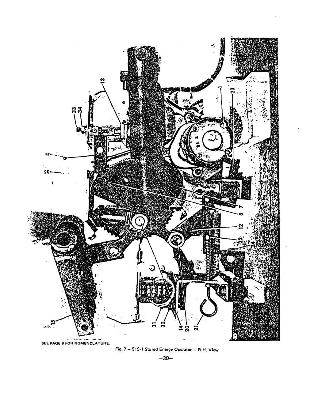
5 ... DESCRIPTION A typical drsui t breaker consists of primary disconnect, arc chute, and operator sections. The primary disconnect section contains the main contacts, which supply power to the load. The arc chute section dissipater the power arc drawn during the opening of the main contacts. The operator section cont'ains the mechanism used to close and open the main contacts. This mechanism corisisk of a.stored energy operator with its associated control circuitry. Arc.in)ekuption is accomplished in free air at atmospheric pressure with the aid of a selfinduced, magnetic blowout field and forced air draft. When the trip solenoid is energized, loid current..iq.being carried by the main contacts. As the csntacts open, the main contacts p.s-: ;. <+.>!: part firsf.andthe.cunent...:w.);r... ii transferred to the arcing contacts. When the arcing contacts part, an arc is esfa6lished between them.., The arc between the arcing contacts is transferred to the arc runners as the arcing contacts open. The transfer of the arc to the arc runner establishes full current flow through the blowout coils, setting up a strong magnetic field. The magnetic field, accompanied by the natural thermal effects of tha heated arc, tends to force the arc upward into the barrier stack. The cool surfaces of the barrier stack cool and de-ionize the arc, while the Vlhaped slots in the stack reduce its cross-sectjon and elongate it, leading to rapid extinction. The arc runners are made of wide, heaq.matedal for maximum heat dissipation and for minimum metal vaporization. A puffer mechanism prwides a forcsd air draft through the main contact area. This aids the magnetic blowout field and natural thermal effects in forcing the arc into the barrier stack for easy extinction.. The breaker Is closed by the operator straightening a toggle in the four-bar linkage (Fig. 7, Item 12). The operator is powered by precharged springs (stored energy). -- (**,.. Stored Energy Qperator.? T $:,.. ' The stored energy operator (Fig. 3) uses charged springs to power the closing operation. Opening is springl/rwrered also, but not with the same springs used for closing. A stored e6ergy operator ctmsists otthne systens: spring charging drive, cam and ratchet assembly, and the four bar toggle linkage (Fig. 4, A - 0). These systems are disengaged from each other except while performing their specific functions. For example - the spring charging drive and cam-ratchet assembly are disengaged except when the cam-ratchet arrangement is being charged. Similarly, the cam-ratchet ad four bar linkage are free of each other except during closing. Stored energy operated breakers normally require a single commercial relay for control. This relay is furnished to match the control voltage.
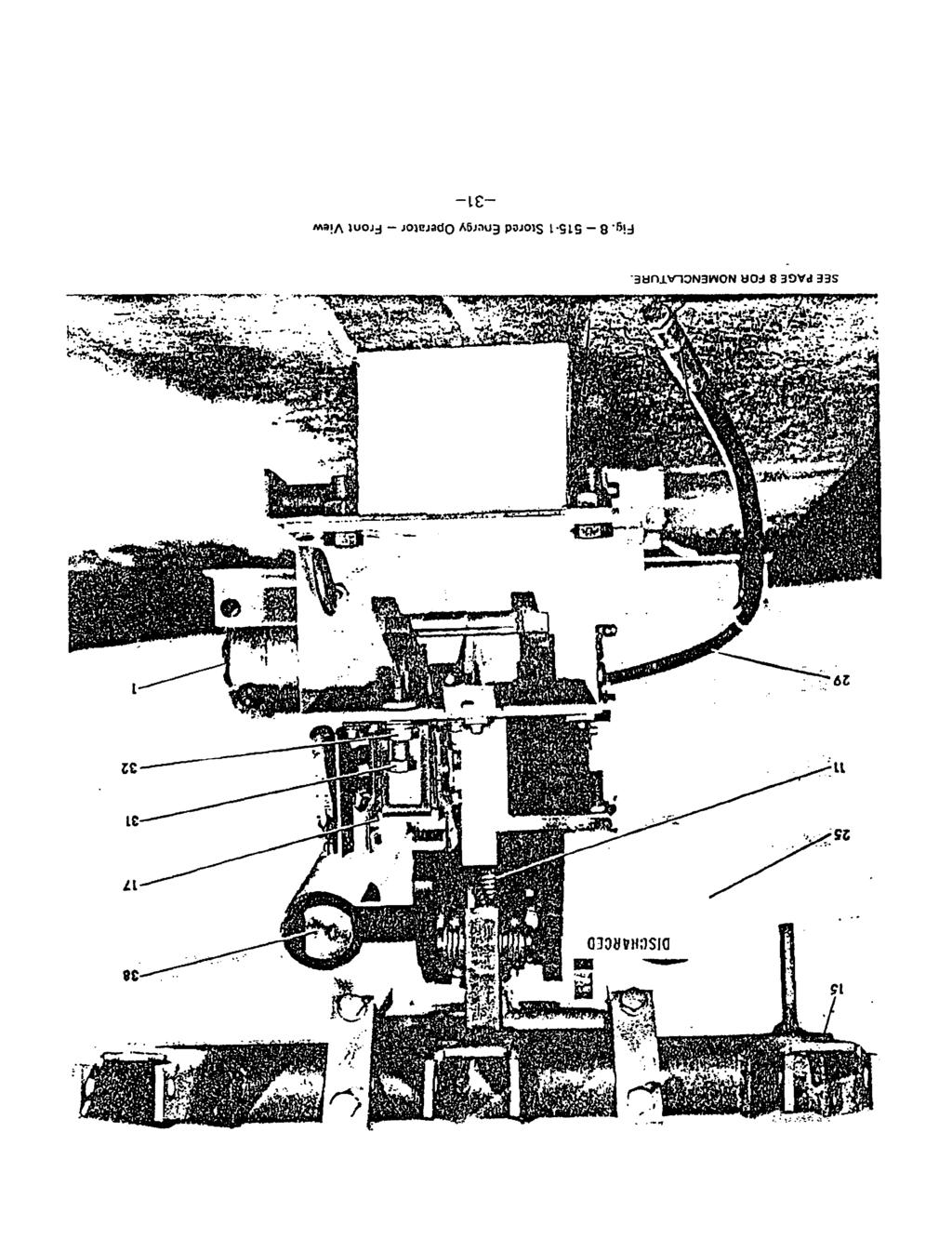
6 f3.eclosing control (Optional - For Reclosing Applications Only) I t The trip latch check system provides the necessary control to perform the reclosing function when the switchgear is equipped with reclosing relays... The system is comprised.of three elements; a magnetic actuator, a non-contacting magnetically oper-. ated Hall effect &itch (sensor) and a timer module. The system performs two distinct functions prior to. enabling the reclosing operation.... :.,&;g.&,enses that the trip latch has reta~rned to its reset position, and is ready to receive a., rfb.+ce,clo~ing operation.. r. :.... I.. ;;j :&L,@" && :.. 2..'a...5 i?.:~,. lrnpo$s.y-?q:;m3. CII, delay following latch reset to insure the linkage -assembly has fully reset and '.... :.... : then appl'ies power to the spring release coil.,..". ; ti' 'The. nbn&tacting.uk.;r...i:. magnetically operated Hall effect switch and magnet actuator combine to perform, proximi~de'tection of-the trip latch tail. The speed of operation and lift expectancy of this proxim-....q.*e..,,:j.,;ity...,.iien.. or system is not limited by mchanical actuation as no physical contact between the actuating.. '. magnet and Hall wi-tch exist. The switch consists of a Hall sensor, trigger, and amplifier integrated on ' ' a silic6.n chip. Its complete encapsulation isolates the device from environmental affects. -.*~fl! '(.:... : AUXILIARY EQUIPMENT.. ;:-; ',d4%c s..: Aux~ltary.. Swttch :.. ~a'jj -!;?:., Mounted on the breaker, the auxiliary switch is normally used to open the trip circuit when the : circuit breaker is opened. As this multi-stage switch operates from the breaker disconnect ;$'blades, circuitry dependent on the position of the breaker, such as indicator lights, etc., is I #red through this switch. The individual stages are easily converted to "a" or "baa without..,:: disgssembl ing the switch (Figure. 5)...-'. I.,....'.:.. a. Capacitor. Trip Device A capacitor trip device is common!y used with circuit breakers having an ac control supply.-, instcil:led iiv ieinote locations of unattended substations where battery cost and maintenance are 5-nd'kiiabl e.."!;'.. '. In these cases, the capacitor trip device may be charged from the same stepdown aransformer thit is used to energize the breaker-control; This stepdown transformer shduld be~connected to tb,jine. nt side of the breaker. +*r;l:.tq<... To apply to capacitor trip device to existing breakers originally shipped with dc trip coils, contact your Siemens-Allis sales representative. TRI~SOLENOI D en i s I L:,:.:.. I Normal electrical tripping (opening) is caused by the trip solenoid (Fig. 8, 17) which is designated 52TC on the schematic of Fig. 9. The trip solenoid is energized by operation of the circuit breaker control switch and the protective relays which are mounted on the switchgear.
7 ARC CHUTE ASSEMBLY Each arc chute (Fig. 6) consists of a flame retardant cnvelope which provides phase isolation for ;:yl. interruption and venting of the by-product gases of interruption. The arc chute contains - 1. Jhe stationary end ark runner (4) and moving end arc runner (31 towhich the arc.-terminals transfer from the arcing contacts. The arc runners form paths for the arc terminals to travel up the arc chute. 2.. The stationary end blowout coil (IS) and moving end blowout coil (13) which connect. their respective arc runners to the top and bottom bushings. The current in these coils,creqtes the magnetic flux which passes through cores (18), ole pieces (22) and the 'i&e between the pole pieces. The action of this flux on the arc forces the arc up the barrier stack Thebarrier... stack (23) consisting of a number of refractory plates, with "V-shaped". slots,.- cemented together..the barriet stack cools, squeezes and stretches the arc to,.... -force a. quick interruption Jhe barrier (1) containing coolers (28) through which the by-product gases of interruption past, compietes the cooling and deionizing of the arc products. Arc chutes-are tilted to expose contact area for inspection of barrier stack (23). The arc chutes may also be lifted and removed from the breaker. Unfasten front and rear coil connections before'tfltfrig ar removtng arc chutes CIRCUIT BREAKER OPERATION tr{a7: Normal -- Normal circuit breaker operation is controlled by cubicle mounted controls or other.r.. control devices. The closing springs of stored energy operated breakers wi I I charge as soon as the breaker control bus is energized. Check the motor cutoff adjustment (page 36) if springs do not charge.., - Opening Breaker --Stored energy operated breakers can be tripped manually by depressing the trip rod (43), Fig. 2, or electrically by energizing the trip circuit. This rotates the latch that allows the closing linkage to collapse and reset. Closing Breaker -- When the springs of a stored energy operated breaker are fully charged, it can be closed by pulling the manual close pull rod (21), Fig. 7, or electrically by energizing the closing..... circuit. This rotates the latch that allows the springs to close the breaker... ~,.
8 6~!i~i.~>~;~i<i~ STORED ENERGY OPERATOR DESCRIPTION OF OPERATION.'f.-- Energizatiori of the Breaker Control Circuit will cause the spring charging motor (4, Fig. 7), to start charging tho cl&sing springs (6, Fig. 3). The spring charging motor (1) will drive the dri~i~~,~owl (2, Fig. 3), through on eccentric drive shaft (3, Fig. 3). The driving awl (2) will turn.tho,ratchet wheel (4, Fig. 3), counter-clochise one tooth at a time. The holding pawl (5,Rig. 3) will hold the ratchet in position between driving strokes of driving pawl (2). This charging opetation will continue turning the ratchet wheel (4) counter-clockwise a tooth fat.a 'time until the closing springs (6) are fully charged (dead center). The motor will drive the ratchet wheel past this dead center position and the closing springs (6) will aid rotation driving the mtchet wheel and cams counter-clockwise until spxng release rollqrs (8, Fig. 7). on the inside surfaces of cams (7, Fig. 71, engage the close latch (9, Fig. 7). This arrests the motion+of the ratchet wheel (4) and the cams (7') and holds the operator in the fully charged position. 'xs the cam and ratchet wheel go over center, the motor cutoff switch (10, Fig. 3), is actuated to de-energize the spring charging motor (I). The spring charging motor then coasts to a stop, driving pawl (2) oscillating in the toothless section of the ratchet wheel. The.mo tor c$off >.,.. switch (10) provides Four functions: C It de-energizes the spring charging motor (1 1; 2. It opens a contact in the anti-pump relay circuit;. 3. It sets up the closing coil circuit; NOTE: 4. It can be used to energize an indicating light to indicate that the closing springs (6) are fully charged. A close latch check switch (16, Fig. 31, is in the motor circuit.the close latch check switch rnonitorr the. osition of the close latch (9) and will prevent charging of the closing springs e (6) electrically unless the close latch (9) is in the correct position. Astthe,energy.is pos~t~oned.:.;' s:.,; stored in the closing springs, the four bar linkage (12, Fig. 7), &it\ be by ihe linkage reset spring (11, Fig. a), which acts to cause cam follower rollers (13, Fig. 3); to follow the surbce of cam (7, Fig. 7), until the I inks are in a reset pori ti'on, and... rollers (20, Fig. 3), to be psi allowing..,=.*: fatch,*'>w:.... The" duargd'porition of the operator is shown in Fig. 7. RECLOSING CONTROL (Optional - For Reclosing Applications Oniy) tioned in front of trip latch (1 8, Fig. 3). The electronic solid state time delay module works in concert with the trip latch sensor system. The time delay module consists of an electronic timer and an electro-magnetic relay. The elementary diagram, Fig. 9, shows the timer module receiving power between terminals 1 and 3. Terminal 3 is tied to the common side of the closing control rourec. Terminal 1'is tied to the high side of the closing control source thw auxiliary contact (528) and the closing source contact "CSC". The trip latch sensor system consists of the magnetic actuator and the Hall effect switch.
9 ' The tirrie delay moduie IS nor erreryt~od LI:~;,; the breaker is cllorgcd, operr ~IIJ rhe closing source switch "CSC". is closed. With the latch reset at the instant "CSC'' closes, the timer modules internal relay with normally open contact operates with no intentional delay (40ms electro-mechanical delayl'to connect the spring release solerioid thru timer module terminal 2 to the high side of the closing rou~ce, ~~l\latln~ - the breakers closing 3:..;.i'. If at t@tlm$:the closing source is applied, the trip latch is not ifset, the timer module will assume a delayig-made of operation. Upon latch reset a predetermined delay will be imposed before the timer:~~@tay.,clores energizing.the spring release solenoid. The complete trip latch check system is noffbj$ec;ted.by broad variation:of closing source voltage. The time delay error caused by tem9=r@turqr, extremes of 40" to 65' C is a minus 3% to plus 5%.!,":.;j j!?,.:.. BREAKERCLOSI NG CYCLE Energizing-thespring release solenoid (13. Fig. 71, will drive thdctose latch (9, Fig. 7). away from the sphng release rollers (8, Fig. 71, on the cams (7, Fig. 7). releasing the stored energy in the -, ciosing springs (6, Fig. 3). The closing springs (6) will drive'the ratchet wheel (4,'Fig. 3), and the cams (7, Fig. 7). counter-clockwise at a high rate of speed. The cams (7) will engage the cam fdlower rollers (14, Fig. 71, of the four bar linkage (12, Fig. 7), and drive them forward causing the fiurbir linkage to become straight. the four bar linkage (12) becomes straight, it drives.the radius srm (15, Fig. 71, upward causing the breaker contacts to clck and the opening. spiings to' be charged. The cams (7) drive the four bar linkage (12) over toggle and against the frame thereby latching the breaker contacts in the closed position. SPRING' RECHARGE AFTER CLOSING When thy closing cycle has been initiated and the cams (7, Fig. 71, begin to turn, the motor cutoff switch (10, Fig. 3);resets itself. A "b" aux switch of the b.reaker opens de-energizing the spring release solenoid (13, Fig. 7). The close latch (9, Fig. 71, returns to its reset position and the close latch check witch (16, Fig. 31, closes and energizes the spring charging motor (1). The closing springs (6) are then recharged as described earlier. TRI PPI NG CYCLE Energizing th$ trip solenoid (17, Fig. 3), will drive the trip latch (18, Fig. 3), away fmm latch r~lle~~(~o~,.fig. 3). on the four bar linkage (12. Fig. 7). This allows the four bar linkage to collapse and the breaker contacts will open. If the closing springs (6) are in the Charged posiiio~thel'inkqe reset spring (11, Fig. 8). will immediately reset the four bar linkage (12). If the closing springs (6) are not charged, the linkage reset spring (1 1) will not reset the four bar linkage (12) until just before the closing springs (6) are completely charged.
10 STORED ENERGY OPERATOR-COMPONENTS NOMENCLATURE h t &i i ; 'To &i! 8i 6: ''06scription of. 0perat.ion" Figures 3, 7 and.8. 1, Spring Charging Motor 2. Driving Pawl 3,. Eccentric Drive Shaft 4. Ratchet Wheel 5j~Holding Pawl %&losing Springs : 7:;. cams...'.... Re-lease Rollers :&%&&ing..baa$ be6,..;. r. c. -1 ;\*tor. Cotoff Switch $&@N;69e R a t Spring $Q+4F'i,ir: Bar.. Linkbge,.. :&llers -(Main Toggle Ral I) 2&#a.w,41.Clo&, Pull Rod.. 22-&5pr.in-g. Pisc hme: RoUer Fcee Height Ad justmen t i3a~~zing~~ischcr~ -Close Mch. Yoke End Ad justment, 24."~~i1& ~ieharge Roller &$-f,qrq~.y?$char~e Indicator. Z6.*Oird\ar~q.;% -~;p.-*.... Indication. ~di".sknb 27,';-C)arge Indication. Ad just@enf,. 28.$&$inkin -v... ~2riing lnterbk Adj ustrnent 29::'~ciri~al.shaft ( Operator) 30. '&i\i -Pumping Relay 31. Trip'latch Bite Adjusting Screw 32..Trip Latch Bite Adjusting Locking Nut 33. Close.Latch Bite.Adjusting Scrw 34, Clob 'Latch.Bite Adjusting Locking Nut 35, Motor cutoff Switch Actuato; 36. Lower Link Stop 37. Roll Pin Striker 38. Aluminum Spring Drive Blocks
, anti-pumping relay (30, Fig. 31, and the close latch check *itch (16.). The typical control arrangements elementary diagram is shown in Fig, 9.")
11 ELECTRICAL CONTROL The normal control for this operator is contained upon a control panel mounted at the rear of the unit. It consists of the motor cutoff switch (10, Fig. 3), anti-pumping relay (30, Fig. 31, and the close latch check *itch (16.). The typical control arrangements elementary diagram is shown in Fig, 9. (Check schematics furnished with switchgear as wiring arrangements may vary.) Spring., Charging The spring chargirig motor power:is supplied through terminals 3 and 4, Fig. 9. The mechanical interlock isa switch operated by the breaker release lever (foot lever) which opens the motor circuit when the lever is depressed. The close latch check switch is closed when the close latch (9, Fig. 3) is in the reset position. The 88 switches are shown with the closing springs discharged. When the. control is energized, the motor starts to oharge the springs. The 88 witch is operated by a' roll pin striker (37, Fig. 3) mounted in the ratchet wheel (4, Figs. 3 and 14). As the ratchet :wheel and drive blocks charge the springs, the ratchet wheel revolves to the position of full compression, dead center. Beyond dead center position, the springs aid rotation and cause the motor cutoff switch striker to depress me actuator (35, Fig. 3) of the 88-1 switch, opening the motor circuit and the 88-3 contact in.the anti-pumping relay circuit. At this instant, the spring charging motor coasts to a stop with the driviirg pawl (2, Fig. 31 oscillating ilce!y olr!he smooth portion of the ratchet wheel. Closing Circuit." ' The standard control circuit for a stored energy operator as shown in Fig. 9. When the close control switch iiclosed, the circuit from terminal 7 through 88-2 and 52Y 1 to 528 through trip latch timer, Fig. 12 (when furnished), to terminal 6 energizes the closing coil, closing the breaker. As soon as the closing springs are discharged, the 88-3 switch contact closes to energize the 52Y relay. If the close control switch remains closed, the 52Y relay remains picked up through contact 52Y2. Control switch has to be released to reset control for another closing operation. This forms the anti-pumping relay circuit which prevents the circuit breaker from reclosing immediately after a trip free operation. If control power is momentarily lost during closing, upon re-energization, the 52Y relay picks up instantaneously through contact 88-3 maintaining the anti-pumping relay circuit prior to complete spring charging. \ Close Latch - Mechanical and Electrical Interlocks The close latch must be fully reset to receive the cam mounted spring release rollen at the-end of the charging cycle. To insure the close latch is in this fully reset position, an electrical and mechanical interlock is provided. The close latch check switch (16, Figs. 3 and 15) consists of a snap-action type switch mounted in close proximity to the close latch. A striker plate at the tail of the close latch engages the switch's actuator slightly before the fully reset position isachieved, and actuates ' the switch prior to the latches reaching the fully reset position. At the time of actuation, a contact closes initiating the charging sequence. The switch operates with ven/ small differential, and this sensitivity coupled with the close latch biased engagement of the spring release rollers provides a positive sensitive interlock.
12 ..... The mechanical interlock (Fig. 17) preventstsm&"al chargi&j of the breaker if the close latch is not adequately reset. A linkage attached by a clevis to the close.,-).- latch extends down the C.:.. side of the biiiker fr&e to me drivinp pawl mechanism. An extbnsion of the interlpcks ~inka~e'~asski above thedriving pawls constant force returti spring..if the.cl&e latch fails to return to a fully rqset.position, the linkage extension thrusts the driving pawl's return spring downward preventiag the driving pawl's engagement of the ratchet wheel, thus mechanically inhibiting either manually or electrical spring charging.
13 ADJUSTMENTS Adjustments are factory set and checked before and after numerous mechanical q~ations on every breaker to insure correctness. No adjustment checking should be necessary on new breakers. If a malfunction occurs, check for hidden shipping damage. The following will help you make the correct adjustmentswhen replacing a broken or worn part. CIRCUIT BREAKER TIMING A comparison of circuit breaker timing at any period of maintenance with that taken when.the bi-eaker was new will indicate the operational condition of the breaker mechanism. A time variance of more than 1/2 cycle (8.3 ms) on opening and 2 cycles (33.3 ms) on closing indicates a maladjustment of friction buildup. A hole (item 29, Fig. 10) in the movable contact arm is provided for connection of a speed analyzer. PHASE BARRIER ASSEMBLY Full size barriers of high dielectric flame retardant material isolate each phase (Fig. 2). To remove phase barriers, lift panel spring assembly (13) out of slots (14) to release panel (32). Lift and remove panel (32). Remove screws (23 and 39) from barrier (22). Remove screws (2, 48 and 49). Remove rear barrier (25). TILTING ARC CHUTES Remove phase barriers as described under "Phase Barriers," above. Refer to Fig. 2. Remove Allen Head Capscrew (51 - not illustrated) and screw (37) on each phase to disconnect blowout coils. Position arc chute support at the rear of the breaker (Fig. 21) and tilt back the arc chutes. After arc chutes are tilted back to their normal position, make sure al l screws have been replaced and tightened securely on all phases before phase barriers are replaced. Note: MAKE SURE THAT BLOWOUT COILS HAVE BEEN RECONNECTED. BARRI ER STACKS The barrier stacks (Fig. 6) are fragile and must be handled carefully. Inspect the barrier stacks for erosion of the plates in the arms of the slots. The borrisr stacks should be replaced when a milky glaze appears on the full length of he edges of most of he slots. They huld also be replaced if plates are broken or cracked. When cleaning the breaker and cubicle, inspect for pieces of barrier stack refractory material which would obviously indicate breakage. To remove the barrier stacks, tilt back the arc chutes, remove screws (2) and barrier (1) from each arc chute. Slide barrier stack (23) lhrough top of arc chute. When replacing barrier stack be sure the v-shaped slots go in first.
14 '*h'ingi jht &&act pressure is in proper adjustment when a pull of 4 to 6 pounds (1. I kg) is required to move the disconnect toward the open position. This meosuremerit is obtained as follows: (Fig. 10)... Remove pin (12) and detach link (8) from the disconnect arms (18) and (19). Move the disconnect to a &&izn JIM of contact maw. Attach a spring scale to the disconnect inches (216 mm) abn(sqcr&;(24), and in a direction perpendicular to the longest edge of the disconnect arm. Measure m'$$8l&.!nove the disconnect toward the open position after Ran of motion. Read scale while disconnect is'moving through normat opening stroke.,.,.111-i Adiustment. i,s made by tightening (or loosening) nut (1 4). Before attaching link (8) to disconnect arms (18 and 19), check contact alignment and contact lead (below and next page). v The arcing contact hinge joint (Fig. 10) is in propd adjustment when each spring washer (1 5) is de flected abproximately inches (0.4 mm). This adjustment is obtained by tightening nut (4) until all pats just touch, then tighten the nut 3/4 ro 1 turn more. ''.... CONTACT ALIGNMENT AND REPLACEMENT The main and arcing contacts ore an integral part of the bushing assemblies and are carefully aligned with the upper and lower bushings before shipment. Normally, no further adjustment is necessary. Use these p&cedum if it becomes necessary to change contacts or reset contact alignmat (refer to Figr 10). Procedure A. Horizontal Alignment 1. Push stationary contact fingers (item 11, Fig. 10) as far back as they will go on stud. 2. Using maintenance closing procedure, move the disconnect towards the closing position until it touches a main contact finger (view A-A, Main Contacts Engaging, Fig. 10). Dimensions "C" should be no greater than.020 (0.51 mm) with one contact touching 3. Adjustment is made by loosening two nuts (22) ad rotating the entire contact a;wnbly. Check alignment (dimension "C") after nuts (22) are tightened, rfi; :?: ~li~nrnent is checked and adjusted on each phase separately. Be sure there are no binds between.antacts (11) that could prevent wiping action with the disconnect arm, -,
15 Procedure 0. Contact Penetration (Stroke) 1.. Chtcict penetration should be checked and adjusted only when the contacts are properly aligned ; 2, ' Chock that open gap i*dll is approximately correct to a-void over penetration (*e Procedure Dl - 3: Using.powero closing procedures, close and latch breaker. The spread of the contacts (view "A-A", Bl;ea&e&LatchedJ should be 118 to 3/16 inch ( mm). This is the total of.the two gap..t$mgsions"a" measured on each side of the contact centering tube between the brass tube and the. flatistop -... surface on the contact. Each "a" dimension is normally 1/16 to 3/32 inch ( mm). 4. With the breaker open, adjust by increasing or decreasing length of link (8) by turning nut,. (16). Adjust each ha st separate1 y. <+ct'?c. % ' Piocedure C. ~rcin~.contact Lead Arcing contacts are adjusted only after the main contacts have the proper alignment and penetra* 2* arcing cmtacti should make before the main contacts. To measure and dilj&t e& phase: 1..,$y$$atipnary main contacts back on stud. 2; : the maintenance closing procedure, slowly move the disconnect arms toward the : cl&ed position until a dimension of 114" * 1/32 (6.4 * 0.8 mm) can be measured be tween the lower stationary main fingers and the disconnect arms of the cloest phase.,:;(s~$tp,_lo dim. b.view A-A arcing contact engaging). The moving disconnect arm.:,: shout be pushed back when making the measurement. ::g!.ynemr~~~~. 3. With thedisconnect arms in proper position established in step 2, adjust nut (1) to. have.@e poving arcing contact touch the stationary arcing contacts. (Push the moving ading contact back when setting.) 4. Advance maintenance closing to obiain proper individual positions of the other phase' disconnect arms in accordance wittj step 2 and set arcing contact lead in accordance with step 3. (~irnul&neous touching of arcing contacts on all three phases is not required. Do not impair penetration of arcing contact lead setting in an attempt to optiwite.). P Procedure D. "Breaker Open Position" h:##- ;, ;. Dimension d (Breaker Open illustration of Fig. 101 is measured between the.disconnect arm and the bottom of the second finger from the top in the main contact assembly. The open position is derermined. by the setting of the rod end (40, Fig. 21 at the top of the puffer piston rod. The rod end (if &'ko low] can affect the trip latch roller clearance (Fig. 11). The optimum setting is to obtain the maximum open contact gap "d" while maintaining the specified trip latch roller clearance (see trip latch adjustment page 14). A dimension "d" of less than 3-1 1/16 in. (93.7 mm) indicates improper adjustment -13-.
16 AUXl l l ARY SW l TCH The type Q-10 auxiliary witch has been tested and adjusted at the factory. Contacts used in the breaker control circuit should not require further adiustmei.lt. The mi tch (Fig. 5) is designed so that the individual contacts moy be repositioned in fifteen degree steps without disassembling the switch. Using long-nosed pliers, move the mtor contact (16) in the slot of the shell (14). compressing spring (15). This will free the rotor from the retainer (17). Rotate the rotor to the desired position and release.be sure the rotor springs back solidly against the retainer to fully engge v the rotor and retainer teeth. l NTERLOCK PLUNGER The foot lever breaker release (20, Fig. 2) operates the interlock plunger (18, Fig. 21 as well as the trip latch. Depressingthe lever trips the breaker and raises the plunger. This frees the breaker so that it can be moved in its cubicle. The interlock system is in proper adjustment when the plunger is positioned 1-11/16 to 1/13/16 inch ( mm) above the floor line, and causes tripping of breaker contacts'when it is raised to a level not more than 2-1/16 inch (52.4 rnm) above the'floor line. The latch tripping rod associated with the foot lever should be clear of the trip latch by 1/32 to 1/16 inch (0.8'- 1.6 mm) in the relaxed position (18, Fig. 3). I The foot levir'kan be padlocked by matching holes in the breaker frame with those in the lever am. In the padlocked position, the foot lever will be halfway down; the breaker will be trig-free; the interlock plunger will be between 2 and inches ( mm) from the floor line and will hold the breaker in any of the three positions within the cubicle. TRI P LATCH ADJUSTMENTS Trip Latch Clearance Adjustment (Fig. 1 1) - this adjustment is to -be performed afier completing the arcing contact touch and main contact penetration adjumntr referenced This adjustment is necessary to insure proper clearance between the trip latch and trip latch rollers. The puffer (or snubber) height adjustment will accomplish this purpose, and in no way will affect the penetration adjustment. Loosen Lower Link Stop and rotate to permit maximum Lower Trip Link movement Adjust puffer (or snubber) height to rotate radius arm and four bar linkage until a.030 to.q60 ( mm) gap appears between the trip latch and latch roller. Lock in place. Rotate Lower Link Stop until it touches lower link and lock in place. Recheck dimension "d" as described in procedure 0, page 13. Trip Latch Bite Adjustment - trip latch bite is established by setting the latch tail top surface 51/16 (7.9 mm) below surface of selfclinching nut as shown in Fig. 12A. Lock securely with jam nut One turn of adjusting screw will alter the gap inches (1.57 mm). This adjustment should produce to inches ( mm) of latch bite as shown in-fig. 12C.

17 and TRIP LATCH CHECK SENSOR ADJUSTMENTS (FIGURE 128 AN0 12D) The magnetically operated Hall effect switch (sensor) and actuating magnet are preasambled to the operator. The unit can be adjusted by advancing the threaded bushing through the tapped hole in shelf until a gap of ( /+.38 mrn) is achieved between the surface of the switch and the top of the shrink tubing holding the magnet actuator assembly to the trip latch. With this gap achieved, the sensor may be locked in place. Functional electrical ten on breaker may be made to confirm senson operation. The timing modules nameplqte end rated voltage should be checked to insure it matches breaker closing control voltage. The timers delay adjustment has been previously set and should not be altered. Remove wire from terminal 2 on timer module and insulate. Open breaker and charge opening springs. v Apply closing voltage e - - (led) adjacent to delay adjustment. The led should be brightly illuminated when the trip latch is fully reset. Depress latch with manual trip lever and observe the led goes out. Release trip lever and the led should come on. This sequence confirms sensor operation. Do not apply closing control voltage for longer than two minutes while performing this test. MANUAL CHARGING OF CLOSING SPRINGS: To charge.the closing springs manually, disconnect control power before inserting the manual charging crank in the socket at the lower left-hand corner of the breaker. ~u'rn the crank in a counter-clockwise direction to charge the springs. Note: Never turn crank in clockwise direction as this can damage flexible shaft. The effort to charge the closing springs will fluctuate and will increase to a peak and then decrease. At the point of lean effort an dudible click will be heard and the effort to turn the crank will drop to near zero, continue to turn crank 3 or 4 more turns, the mechanism is now fully charged. The breaker may be closed by pulling the manual close pull rod. CAUTION! I MAINTAIN A FIRM GRIP ON CRANK The closing springs are charged through the driving pawl and ratchet wheel and are thereby indexed by the holding pawl. Some springback can occur between tooth positions'on the ratchet wheel. MAINTENANCE SLOW CLOSE With the breaker removed from the cubicle, manually charge the closing springs as previously described and remove charging crank. Then, from the rear or stud side of the breaker, attach the spring blocking device, Fig. 13, by fastening it in the slots in the closing spring tubs. Stay clear of the breaker contacts and pull the manual closs pull rod at the front of the breaker. This will discharge the closing springs against the spring blo2king device during which the breaker wntack will move slightly toward the closed position. Place the manual spring charging crank back in the rocket at the lower left corner of the breaker. By turning the crank counter-clockwise the breaker contacts may be slowly c lod for checking contact alignment.

18 CAUTION!! MAINTAIN A FIRM GRIP ON CRANK 1 As tho conhsh will clou in increments predicated by the teeth on the ratchet wheel, springback will occur betwee" feeth positions....i*v:. - R&O+P;C OF 5PRlNG BLOCK! NG DEVICE,. ~?fj;,:~~<;~~,f~ : :, To remove the closing spring blocking device, Fig. 13, the closing springs must be fully charged. The spings may be charged manually by inserting the charging crank and continuing counter* clockwia-rotation..the inain contacts will go ful i y closed as the four bar linkage toggles.. Upon continued rotation, the closing springs will be pitked-up as noted by incrrmed effort in crankim. bncnue rotation until the springs are fully charged. A sharp click will be heard as tha$&#'fel 4t,: :.., ease. rollers angage the spring re1 ease latch tndicating full sprin~ chargo has been achiwal. The spring blocking device may now be easily removed by pulling the blocking portion from the slots in the spring tubes.. RE)~~&Q&~;;~.oF 8:;.. L>.,..' 'CLOSING SPRI.NGS (SPRINGS MUST BE DISCHARGED) The Closing Springs may be quickly and safely removed from the breaker. Remove two of the four bolts holding the spring bearing block at the rear of the breaker. These bolts should be diagtmally &te each o@w. Insprt studs approximately 6" (1 50 mm) long in place of bolts. Remove the remaining two bob fsy!*ifting the spring load t6 the 6" (1 50 mm) long studs. The spring bearing block can then be backed off by alternating backing off the studs. To install the closing springs the reverse procedure should be used. the -king bewing block top surface should be wen with the bracket of the frame. The four bolts should be torqued to 50 ft. I br (67.8 N-m)..If the charging ratchet and cams are to be revolved with springs removed, it is advisable to remove two aluminum spring drive blocks (Item 38, Fig. 8) secured to the ratchet and cam crankpins by retaining rings. ThThwIgins if not removed or held essenti.ally in a horizontal position may jam while revolving &f(...' the cam. and mt&et assembly. 4~u.1~1.. Yfll':-Jfj&.? : : Motor Cutoff Switch - The 88 motor cutoff switch assembly (Fig. 14) is factory adjusted. If it should become inoperative, entire unit must be removed and inspected for contact wear. Replacement rn8y.ije' necessary. - Motor Cutoff Switch Adjustment - This adjustment is most conveniently performed before installkingthe charging springs. Advance ratchet and cam assemblies to position shown (Fig. 14). The holding pawl must rest behind tho ninth (9) tooth position on the ratchet as counted counter-clockwise from "area" on ratchet periphery which lacks two teeth. With ratchet in the position described above, adjust the motor cutoff switch vertically until its actuator ma& positive contact with the "rollpin striker.'' Lock switch assembly in thk position.

19 Check lateral movement of actuator. Lateral play at end of actuator (tip) should be no more than 1/16" ' (1.6 mrn) max. If adjustment is necessary, snug pivot screw to just bind actuator, and then back off 1/16 to 1/8 turn. Rotate ratchet and cam assembly to insure actuator rides in gap between ratchet and cam without striking or binding..-.,a.::t.,-,..... /(. Close Latch site Adjustment - free jam nut and place latch in horizontal position (Fig. 15). Visual accuricy. Measure. "D" directly above latch pivot. Reproduce this dimension plus 0.062" (1.6 mm) at the latch face as shown in the figure above by rotaling the adjustment screw. Secure jam nut. This adjustment should prody~e a latch bite of to inches ( mm)...i;... Close Latch ~h&k Switch Adjustment (Fig. 15) - This adjustment is to be performed only after completing thee-latch bite adjustment described above.,,i. i%;i C.3 s*.,&>m&*s*8.:. A cleatjly.audib!e,-.-,.-, "click" shouid be heard from the switch with latch spaced 1/32" (0.8 mm) from latch adj'igtmenf sc&w. The latch switch actuator may be bent slightly to obtain witch opehtion at this... point ~&imum permissible bend is 1/8 (3.2 rnm) as shown. If switch actuator is bent, observe latch fully closed against adjusting screw and make certain the witch actuator his not contacted the switch body. A 1/64" (0.4 mm) cleaqnce should exist as show" in Fig. 15;. ' 7t:?i,* TL:,?.,, -..L.. Free Hdght.Adjuwnt ( ~i~. 16) - is achieved by blocking the actuating roller to the indicated height and adjirsting a pair of jam nuts, located on the manual closing pull rod, to maintain the roller in this position.widr blocking removed. Return spring adjusting nut should be set to produce inch ( i T.6"mm) deflection in return spring.. -..> The following adjustments are to be made only after completing the close latch bite adjustment described on the previous page and after adjusting connecting link as shown on Fig. 16. qyj:$ 2Vi, ': Q'& j; * ; Trip Adjustment (Fig. 16) is made by varying the penetration of the "curved actuating rod" in its attachment clevis. A'5/16" (7.94 mmj drill is placed between the upper latch surface and the latch adjusting bolt. A 2.906" (73.81 mrn) block is to be inserted between the actuating rollei- and floor. The "curved" rods upper yoke is nested against a forward roll pin in the-closing latch and the lower clevis is adjusbd to insure the closing latch will not move more than 1/16 (1.6 mm) inches as measured between adjusting screw and latch surface when the 5/76 (7.94 mm) drill is removed. -.-.a.- Overtravd (Fig. 16) -;no adjustment required. Check with 3.125" (79.4 mm) blocking below actuating roller. Closing solenoid link should provide freedom of latch movement without jamming. Close Latch ~echanicat Interlock - this adjustment is to be undertaken only after completing the close latch bite adjustment described above. Fig. 15. Adjust actuator rod displacement from support angle to inches ( mm). See detail of adjusting nut "A".(Fig. 17). Insert a 114" (6.35 mm) drill between upper surface of close latch and latch adjustment screw. Check guide bushings to insure they stand off the frame 114" (6.4 mm) as shown.
20 Free Nut "0" below attachment clevis; and adjust Nun "0" and "C" to depress pawl return spring and pawl until 1416 to 3/32 ( mm) clearance is obtained between tip of pawl and ratchet teeth, This clearance is measured during the clockwise rotation of the pawl as its tip is towara.the ratchet (power stroke). The pawl mu&. berotated using 1/2" (12.7 mm) square insert in the eccentric drive shaft or by low voltage (slow?odfdtion) of drive motor or manual charging. m&i.c,.::'::,! : - '. hum the jam nut "C" attachment clevis to bottom on bracket, and tighten external jam nut "8" securely. MAINTAIN CLEVIS PARALLEL TO FRAME. ji.,.. #' E'::- :. '. Rernklvb 1(4', (6.35 mm) drill, restoring latch to its normal wition. Again rotate eccentric driv*...; :<....: shae%e tip of the'drive pawl should engage the full face of each ratchet tooth with a clearance of %!?, '.03Om(a8'mm)-between. the. base of.the tooth and the engaged tip of the drive pawl.
21 I MAINTENANCE AND TESTING Thorough. peiiodic.. inspection is important to satisfactory operation. Inspection and maintenance fid&ncy depends on installation, site, weather and atmospheric conditions, experience of operating personnel and special operation requirements. Because of this, a well-planned and effective maintenance program'depends largely on experience and practice. ' ALWAB INSPECT A BREAKER WHICH HAS INTERRUPTED HEAVY FAULT CUl3REN.T. All contacts?.i; g&'njnners.-.;:. and arc chutes should be examined to determine if repair or replacement of parts is required. Inspect for pieces of barrier stack refractory material in the cubicle as well as the circuit breaker. ( ' "As Found" Tests -Some users perform "A$ Found" insulation tests using-a megger or Doble testing to give an "As Found" value for 'future comparative indication of insulation change. This is desirable for new circuit breakers if they are to be stored for extended periods, and may absorb moisture and contaminates. Contact resistance tesb can also be made using a ductor. Since wide'variations can occur in insulation values and contact resistance because of atmospheric conditions, contamination and test equipment, discrete values cannot be given. However, making and recording these tests on new equipment, and at regular intervals will give a comparative indication of insulation and/or contact resistance change. Maintaining a permanent record of these values for each circuit breaker should be part of the Maintenance Program. Periodic Inspection and Maintenance Priorto performing any maintenance work, make certain all control circuits are open, and that the breaker has been completely withdrawn from the metal-clad unit 1 CAUTION DO NOT WORK ON THE BREAKER OR OPERATING MECHANISM WHILE THE BREAKER IS IN THE CLOSED POSTION. DO NOT WORK ON THE BREAKER OR OPERATOR WHILE THE CLOSING SPRINGS ARE CHARGED. 1. Reinwe interphase barriers (Refer to Page 11, Phase Barrier Assembly) and clean them and all other insulating surfaces with dry compressed air - a vacuum cleaner, or clean lint free rags. Inspect for signs of corona, tracking or thermal damage. 2. Tilt the arc chutes to expose the main contacts. (Refer to Page 11 and Fig. 21, Tilting c re Chutes). 3. Contacts Examine the contacts, Fig. 10. The major function of the air circuit breaker depends upon correct operation of its contacts. These circuit breakers have two distinct sets of contacts on each pole, main and arcing. When closed, practically the entire load current passes through the main contacts.

22 If thetresisbnce of these contacts becomes high they will overheat. Ihcreid contact resistance can be caused by pitted contact surfaces, corrosion of contact surfaces, or weakened contact spring pressure. This will cause excessive current to be diverted through the arcing contacts, with consequeniovarheatintinp and burriing... verify proper main contact pienure by checking penetration (~kfer to Page 13 Procedure 0). Arcing contacu'are the last to open, and arcing originates on them. In circuit interruption, they carry current only momentarily, but that current may be equal to the interrupting rating of the brea~ef~,lnqlosin~ aping a short circuit, they an the first to close and may momentarily carry considerably more than the short circuit interrupting rating. Therefore, they must make contact to the main contacts. If not, the main contacts can be badly burned. On the:magnetic b toeut air circuit breaker, the arc is quickly removed from the arcing contacts by magnetic forces and transferred to arc runners in the arc chute (Fig. 6). The arcing contacts are e3pendable and may eventually burn enough to require replacement The main and arcing contacts are made of tungsten alloy to resist deterioration due to arcing. If. the surfaces are only roughened or slightly pi&d, they can be smoothed with crocus cloth or. draw filed..be careful not to remove much material, as this would shorten the contact life. If significant erosion has occurred, the arcing contact lead must be checked and adjusted using Procedure, C on Page 13. If they are badly pitted or burned, they should be replaced. (Refer to Page 12). The main contacts may be lubricated per Fig. 20, but DO NOT LUBRICATE THE ARCING p0ntacts.-... r,c;:;,-.-.' Disconnect Arm Hinge Joint Check contact pressure of the disconnect arm hinge joint per Page 12. If the pull is within the 4 to i. -. : 6 ( kg) acceptable range, the joint should be satisfactory. If not, then it should be maintained as follows: \ Refer to Fig. 10. Remove disconnect arms as a unit by removing screw (24), nut (14) and spring washer.... (23). Carefully inspect all contact surfaces in hinge joint. Replace any damaged parts. Silver.. - -er (25) and djacknt surfacer should be clean and free of roughness or galling. However, dip r. :-. coloration. of the silvered surfaces is not usually harmful unless caused by sulfide (insulating) deposits. These should be removed with alcohol or a silver cleaner. '~ubricate silver washer and mating surfaces by applying electrical contact lubricant (Fip.20, J). Reassemble hinge joint Tighten screw (24) arid nut (14). Spring washer (23) and silver washer (25) must be assembled in their original position to assure proper adjustment Adjust per Page 12, "Contact Pressure of Disconnect Ann Hinge Joint and Arcing Contact Hinge Joint." 5. Arc Chutes Inspect the arc chutes. This includes inspection of the ceramic parts (banier stack and flash plates) for breakage, erosion and din; inspection of the brow out coil insulation; and of the entire arc chute for dirt, moisture or contaminates which might affect insulation strength.
23 Din or contaminates may be rcmoved from tttc :r_.r stack with a cloth, by light sanding or by scraping with the end of a file. Wire brushing or emery cloth is not approved because metallic particles may 'become embedded in the insulating material. Arc flash plates in the lower portion of the arc chute may be cleaned by sand blasting or by sanding with coarse grain paper, to remove glaze and metal deposits from the surface.,. Blow out particles with dry compressed air. Small cracks or pieces chipped or broken from ceramic parts may be ignored. A barrier stack split. vertically along a rope seam may be repaired with epoxy cement. A barrier stack split horizontally or one with several broken plates should be replaced. v The action of the arc on ceramic causes slight melting. Small milky glass nodules on the edges and surfaces'of the cerami'c barrier s?ack plates are normal after interruption. With severity and number -- of operations, this melting and glazing increases. When barriers are heavily glazed (milky white along the edges of the V slots) the barrier stacks should be replaced. Blowout coil ankcor* insulation should be inspected for evidence of abrasion; heating or mechanidl swes which could lead to electrical discharge between coil and core. # Mechanically damaged, burned or punctured blowout coils and core insulation should be repaired or replaced. 6. Mechanism - Stored Energy Operator The circuit breaker mechanism should be inspected at 2000 operation intervals (1000.operation intervals for the MA-350 breaker). This inspection should check for loose hardware and-any broken parts. The control wiring should be checked for loose connections and frayed or damaged insulation. The "'close latch check switch," "trip latch check system" (if furnished), and L$mechanical interlock" switch should be checked for mounting tightness. The satisfactory operatido of each switch element should be issured with a continuity meter and manual manipulation of the switching element, and adjusted if necessary. Verify that operation of "Close Latch ~eihanical Interlock" is proper (Refer to Page 17 and Fig. 17).. Afgr.10,000 operations, (5000 operations for the MA-3501, the operating mechanismshould be given a general overhaul and all worn parts replaced. Excessive wear will usually be indicated when adj&ments can no longer be satisfactorily made. The general overhaul will require disassembly of the operating mechanism. All bearings and surfaces receiving wear should be examined carefully.: andrelubricated in accordance with lubrication instructions which follow. The removal of the closing springs will be necessary in order to permit overhaul of the breaker. These springs may be removed as described on Page Lubrication - NOTE: The lubricant supplied with the accessories is intended to be used exclusively on the contacts and must not be used on any part of the circuit breaker mechanism.
24 'a;s7- Recommended.\!.,-;-;.-.. circuit breaker lubrication points are shown in Fig. 18 and 19. The chart (Fig. 20), outlines tw6.'methods of lubrication. Refer to rhis chart for recommended lubrican!,and points of appli&oii. The first method requires no disassembly and is suggefled for the prevention of p~&61irii;s' khich could be created by severe environmental or operating conditions. The second method~follows procedures similar to those performed on the breaker at the factory.' Follow this procedire only in case of a general overhaul or disassembly. Needle and roller bearings are factory lubricated for life and should not require attention. However, the best of greases are affected by time and atmospheric conditions and may require seivice., - To lubricate these bearings when parts are disassembled, the following procedure is recomme"ded.. Clean in solvent wash in alcohol, spin in light machine oil, &ain and repack with Beacon P grease. DO NOT REMOVE NEEDLE BEARINGS FROM THE RETAINING PART.... a 8. Air Puffers Air puffert (E, Fig. 19) are important to the interruption process because they provide a flow of air which'isl& in controlling the shape of the arc column at low current values. This control causes &.b... the arc.-to'make an earlier transfer to the arc runners, thereby energizing the magnetic circuit which T-J:?..$-,.* drrves the8.arc into the barher stack. This action produces a shorter arcing time than would be p&%iijii4 relying only on the thermal effects of the arc to achieve the transfer to the arc runners..-3.4':f: -....R+,.+:... ~uff& slioirtd be inspected during regular breaker maintenance periods. Hoses should be checked forxibili, freedom from kinking or collapse and soundness of connection to mating parts. Cylindeis should be checked for cleanliness and freedom from deposits which might retard the. motion of the piston.,pistons should be checked for free movement within the cylinder and that the seals are flexible and contact the walls of the cylinder. Transformer oil is used on felt seals to keep the material pliable, reduce shrinkage and to provide lubrication. The oil should moisten but not saturate the felt.replace seal material if it becomes iriflexible or does not make contact with the cylinder walls. The aiyutput from the puffer nozzle may be checked with the arc chutes tilted (refer' to "Tilting Arc Chutes", Page 1 1 and Fig. 21. Crush a 4-1/2 x inch (1 15 x 1 15 mm) sheet of tissue paper, place it in the nozzle opening the check to see that it is dislodged when the beaker is opened. 9. Inspect for foreign objects which may have been left in the circuit breaker during previous steps. Check for loose hardware. 10. Check for mechanical freedom of disconnect arm movements by slowly closing the breaker. Reference Page 15 for "Maintenance Slow Close" Procedure. 11. Trip breaker by depressing trip rod, kg. 2, Item Return arc chutes to upright position, fasten both front and rear blowout coil connections and replace phase barriers. Be sure screws on all phases are tightened securely.
25 . 13. "As.. Left?., Tests. -. :2..i,., a. Insulation resistance tests should be made to verify the insulation integrity. These can include megger or Dobel tests. If possible, a high-potential test should be made for one minute at.14,300 volts a.c. or 20,200 volts d.c. With the breaker open check each phase across the open..i... _.. contacts by connecting from the upper to the lower primary disconnects. With the circuit breaker closed, check phase-to-phase and each phase-to-ground...,,.._... (... b. '.A'dielectric test on secondary and control circuits should be made at 1200 volts. c: If desired, contact resistance tests can be made using a Ductor. d. Make a permanent record of all tests performed..,. e. Compare with prior tests. (See "As Found" Tests on Page 19). 14. Inspect the primary disconnect contact finger assemblies, Fig. 2, item >,..;.. Tfie.main contact'surfaces should be clean and bright. However, discoloration of the silvered...,.. &&ces is not usually harmful unless caused by w l fide (insulating) deposits. These should be removed wlth alcohol or a silver cleaner. Slight impressions on the contacts will be caused by the.7.u;ia* ; pre~re and wiping action of the con&&. Minor burn or pitting can be allowed and projecting burrs may be removed by dressing. Nothing more abrasive than crocus cloth should be used on the 1.o ;I:. s~lverelfd'contact surfaces. Where serious overheating is indicated by discoloration of metal and ~r&hding insulation, the contacts and spring assemblies should be replaced. In this case, also C-.';.. invest~gate the cubicle mounted stationary disconnects, (with the switchgear deenergized).. ->:.;, determine the cause of overheating, and take corrective action. :$>>)>.'...!i?. Ti.. ;. '. 15. Prepare the circuit breaker for service by repeating steps 9 through 22 on Page 2.
. Place t-shaped pieces in front of the ballet in lise with breaker wheels (E) and nail.")
26 Move breaker to installation location with fork lift (A) or crane (0). ' Carefully remove protective planic hver or crate. Remove t-shaped pieces nailed' to the:pallet, in front of the rear and front wheels'of the breaker (C &;'D). Place t-shaped pieces in front of the ballet in lise with breaker wheels (E) and nail.to pallet as shown by arrows. in ( 1.. -,. - Slowly roll breaker off pallet (F & GI CAUTION - REMOVE PACKAGING. 6REAKER.S ARE SHIPPED IN CLOSED POSITION WITH THE TRIPR~D AND FOOT- LEVER ENCLOSED BY PACKAGING TO PREVENT OPENING ; DURING S~IPMENT (C).... (F) (GI I Fig. 1 - Circuit Breaker Handling instructions
27 ASSEMBLE BOLTS 5 WASHERS AS SHOWN IN VIEW "A"..... NOTE: Be sure that the small brass spacer wsrher ir installed next to cup insert in contact assembly to allow for floatinpi-don of arrembty.; " This is required a part of sell alipninp feature. OUTER PHASE N I REAR BARRIER SCREW SCREW CONNECTOR NAMEP$A SCREW AUX. SWITCH PISTON STEM FOOT LEVER HANDLE TRIP AOD MANUAL CLOSING PULLROD PLUNGER MANUAL CHARG FITTING SPRING OISCHARG E GROUND CONTACT

28 Fig Stored Er~crgy Operator - L.H. View
29 FIXED POINTS Q MOVING CENTERS FIXED POINTS 0 MOVING CENTERS 1. 1 CL&NG _----- LATCH d- CLOSING SPWNG. - ;.?.." / FOUR BAR LINKAGE FIXEDPOINTS 0 MOVING CENTERS ----, CLOSING SPRING '2, CLOSING FOUR BAR LINKAGE d I TRIP UTC" B/\~KER CONTACtS OPEN L & t ~ ~ ~ ' ~ M A R ~ ~ ~ -.,.., - 3 ' BREAKER CdNTACTS CLOSED SPRINGS CHARGE0 Fig. 4 - Sequence of Operation
30 Fig. 5 - Typ 0-10 Auxiliary Swith
31 BARRIER BARRIER STACK MOVING END FC RUNNER COIL FRONT) CORE I (A) MA-75C, MA-2% SHlELO FLASH PLATE - LEFT F W H PLATE - RIGHT PI-Y1-CLI-U. Fig. 6 - Arc Chutes -29-
32
33
34 (+I FOOT LEVER TC - CIRCUIT BREAKER TRIP COIL 52 CC - CIRCUIT BREAKER CLOSING COIL 52 Y - AUX. CLOSING RELAY ANTI PUMP MCO - MOTOR CUTOFF SWITCH 88 - SPR tng CHARGING MOTOR CLC -CLOSELATCHCHECKSWITCH TLC - TRIP LATCH CHECK SWITCH CSC R RE0 INDICATING LAMP G - GREEN INDICATING LAMP a b - CONTROL SWITCH - CLOSE CONTACT CST - CONTROL SWITCH - TRIP CONTACT TRIP LATCH - AUX. SWITCH - OPEN WHEN BR'KR. IS OPEN - AUX. SWITCH - CLOSE0 WHEN BR,KR. IS OPEN 'OPTIONAL ITEMS FURNISHEO FOR RECLOSING APPLICATONS ONLV. Fig. 9 - Control Scheme for Stored Enagy Operator -32-
35 MAIN CONTACT FINGER [STATIONARY) ARCING CONTACT (STATIONARY) v [MA-250 ONLY) ARCING CONTACT' ARCING CONTACT IRlGHT MOVING) ILEFT MOVING) CHECKNUT VlEW "0-8" VlEW "A-A" (MAIN CONTACTS ENGAGING) Fig Stud and Support Assembly
36 Fig Trip Latch Clearance Adjustment 1
37 ... ADJUSTMENT SCREW MAGNC T~CALLY OPERATED HA;LL EFFECT SWITCH LOCKING NUT IA) -THIS ~IMENSION MUST BE BETWEEN HALL EFFECT SWITCH BASE AN0 TOP OF SHRINK TUB1 NG AS SHOWN. 4 LIGHT'EMITTING OIODE 11 DELAY ADJUSTMENT LATCH ID) OELAY MODULE *. Fig Trip Latch Bitc and Check Swiich Adjustments

38 BREAKER CHARGED AND READY TO RECEIVE SPRING BLOCKING DEVICE: SPRING BLOCKING DEVICE IN CORRECT POSITION FOR INSERTION INSERTION OF THE SPRING BLOCKING OEVICE. NOTE SPRING nlocklng DEVICE IN PLACE READY FOR CLOS - SPRING BLOCKING DEVICE MUST fle DlAGONALLv IN. ING SPRING RELEASE SERTED TO CLEAR BREAKER FRAME. Fig. 13. Maintcnancc Clorc Spri~rg B!otki~q Ocvice lnscrtion -36-
Vacuum Circuit Breaker Type VAD-3
 Instruction Bulletin Bulletin 6055-11 Vacuum Circuit Breaker Type VAD-3 4.76 kv, 29 ka (250 MVA) 4.76 kv, 41 ka (350 MVA) 8.25 kv, 33 ka (500 MVA) 15.0 kv, 18 ka (500 MVA) 15.0 kv, 28 ka (750 MVA) 15,0
www. ElectricalPartManuals. com Instructions for Load Break Air Switch, Type LBF, for Power Centers
 Instructions for Load Break Air Switch, Type LBF, for Power Centers The Westinghouse Type LB 1 F Switch is an air insulated, gang operated, three pole, two position link type load interrupter switch. The
CA Breaker Instruction Manual
 Volume 1 HOMEWOOD PRODUCTS CORPORATION Westinghouse Technology CA Breaker Instruction Manual HOMEWOOD PRODUCTS CORPORATION Compressed Air Circuit Breaker Homewood Products Corporation 820 Washington Blvd.
www. ElectricalPartManuals. com
 Instructions for Parcel-Line Type DH-P Circuit Breakers with Post Insulator Type Pole Units (Supplements I. B. 32-253-2) Westinghouse Electric Corporation Switchgear Division, East Pittsburgh, Pa. 15112
ichards MANUFACTURING COMPANY, SALES, INC. 517 LYONS AVENUE, IRVINGTON, NJ Phone Fax
 Network Protector Instruction Manual Type 316NP ichards MANUFACTURING COMPANY, SALES, INC. 517 LYONS AVENUE, IRVINGTON, NJ 07111 Phone 973-371-1771 Fax 973-371-9538 IM 1232-001B DISCLAIMER OF WARRANTIES
www. ElectricalPartManuals. com SIEMENS-ALLIS INSTRUCTIONS Switchgear
 f J!, SEMENS-ALLS Switchgear ;-.., ----... NSTRUCTONS TYPES FB-500A 1 7.2-kV AND FC-5008 13.8-kV AR MAGNETC CRCUT BREAKERS WTH STORED ENERGY OPERATOR --.n -"' --- - TYPE 515-2 18X10065 April, 1978 NDEX------------------------------------
ABB Automation, Inc. Substation Automation & Protection Division Coral Springs, FL Allentown, PA
 ABB Automation, Inc. Substation Automation & Protection Division Coral Springs, FL Allentown, PA Instruction Leaflet I.L. 41-661.1B Effective: June 1997 Supersedes I.L. 41-661.1A, Dated February 1994 Type
Vacuum Circuit Breakers (Vehicle) Type HKR 7.5kV to 15kV. Instructions Installation Operation Maintenance SGIM-9928C
 Type HKR 7.5kV to 15kV. Instructions Installation Operation Maintenance SGIM-9928C") Vacuum Circuit Breakers (Vehicle) Type HKR 7.5kV to 15kV Instructions Installation Operation Maintenance SGIM-9928C Hazardous voltages and high-speed moving parts. Will cause death, serious injury or equipment
Vacuum Circuit Breakers (Vehicle) Type HKR 7.5kV to 15kV Instructions Installation Operation Maintenance SGIM-9928C Hazardous voltages and high-speed moving parts. Will cause death, serious injury or equipment
EISHO TEK. Vacuum Circuit Breaker
 EISHO TEK Vacuum Circuit Breaker TYPE:SV1-12 INSTRUCTION MANUAL Operation and Maintenance Version TAIWAN CALSONIC SAFETY PRECAUTIONS For safety reason, this equipment should be handled by personnel who
Vacuum Circuit Breakers (Vehicle) Type MSV 5kV. Instructions Installation Operation Maintenance SGIM-9988
 Type MSV 5kV. Instructions Installation Operation Maintenance SGIM-9988") Vacuum Circuit Breakers (Vehicle) Type MSV 5kV Instructions Installation Operation Maintenance SGIM-9988 Hazardous voltages and high-speed moving parts. Will cause death, serious injury or equipment damage.
Vacuum Circuit Breakers (Vehicle) Type MSV 5kV Instructions Installation Operation Maintenance SGIM-9988 Hazardous voltages and high-speed moving parts. Will cause death, serious injury or equipment damage.
Vacuum Circuit Breakers (Vehicle)
") Vacuum Circuit Breakers (Vehicle) Type GER 5kV to 15kV Instructions Installation Operation Maintenance SGIM-9978D Hazardous voltages and high-speed moving parts. Will cause death, serious injury or equipment
Vacuum Circuit Breakers (Vehicle) Type GER 5kV to 15kV Instructions Installation Operation Maintenance SGIM-9978D Hazardous voltages and high-speed moving parts. Will cause death, serious injury or equipment
TRINETICS CSD SERIES OIL SWITCH INSTALLATION INSTRUCTIONS
 TRINETICS CSD SERIES OIL SWITCH INSTALLATION INSTRUCTIONS 33220900 DECEMBER 2011 Caution: The equipment covered by these installation instructions should be installed and serviced only by properly trained
SL-6 & SL-6A. I UNION SWITCH & SIGNAL l[ml 645 Russell Street Batesburg, SC Service Manual Field and Shop Maintenance
 I UNION SWITCH & SIGNAL l[ml 645 Russell Street Batesburg, SC 29006 Service Manual 3011 SL-6 & SL-6A Outlying Switch Lock Field and Shop Maintenance April, 1979 A-79-500-1496-3 1979, Union Switch & Signal
CR193 Vacuum Limitamp* Contactors
 GE Electrical Distribution GEH-5306C Maintenance Instructions CR193 Vacuum Limitamp* Contactors Contents Section 1 Introduction... 3 General... 3 Section 2 Description... 4 Principle of Operation... 4
Vacuum Circuit Breakers (Vehicle)
") Vacuum Circuit Breakers (Vehicle) Type 5 HVR 4.16kV Instructions Installation Operation Maintenance SGIM-9948D Hazardous voltages and high-speed moving parts. Will cause death, serious injury or equipment
Vacuum Circuit Breakers (Vehicle) Type 5 HVR 4.16kV Instructions Installation Operation Maintenance SGIM-9948D Hazardous voltages and high-speed moving parts. Will cause death, serious injury or equipment
PowlVac Type PV STD/CDR Vacuum Circuit Breaker
 Instructions PowlVac Type PV STD/CDR Vacuum Circuit Breaker Installation Maintenance Renewal Parts POWELL ELECTRICAL MANUFACTURING COMPANY 8550 MOSLEY DRIVE HOUSTON, TEXAS 77075 USA PHONE (713) 944-6900
Tooling Assistance Center
 Safeguards are designed into this application equipment to protect operators and maintenance personnel from most hazards during equipment operation. However, certain safety precautions must be taken by
ProTrip Conversion Kits. For GE Types AK-15, AK-25, and AKU- 25 Low-Voltage Power Circuit Breakers INTRODUCTION. DEH Installation Instructions
 DEH 40026 Installation Instructions g ProTrip Conversion Kits For GE Types AK-15, AK-25, and AKU- 25 Low-Voltage Power Circuit Breakers INTRODUCTION GE Conversion Kits are designed for upgrading existing
GE Industrial Solutions. User/Installation Manual for 4.76kV -15kV SecoBloc
 GE Industrial Solutions User/Installation Manual for 4.76kV -15kV SecoBloc Index General Scope...3 Standards...3 Operating conditions...3 Technical specification...3 Basic structure Features...4 Operation...4
GE CONSUMER & INDUSTRIAL
 GE CONSUMER & INDUSTRIAL GE POWER/VAC Vacuum Circuit Breaker Type PVDB1 15.5 kv ML18/ML18H Spring Operating Mechanism Instruction Number GEK-90211C Table of Contents Section 1. Introduction 1-1 Safety...
Vacuum Circuit Breakers (Vehicle)
") Vacuum Circuit Breakers (Vehicle) Type DTR 7.5kV to 15kV Instructions Installation Operation Maintenance SGIM-9938B Hazardous voltages and high-speed moving parts. Will cause death, serious injury or equipment
Vacuum Circuit Breakers (Vehicle) Type DTR 7.5kV to 15kV Instructions Installation Operation Maintenance SGIM-9938B Hazardous voltages and high-speed moving parts. Will cause death, serious injury or equipment
RENEWAL PARTS ORDER GUIDE. FCV-500 AND FCV-750 VACUUM CIRCUIT BREAKERS WITH STORED ENERGY OPERATOR NO V
 ,.. \... I'
www. ElectricalPartManuals. com INSTRUCTION BOOK h'o. AIR CIRCUIT BREAKER Types 50-DB-ISOE and 50-DB-2501 j,," ,,,,< W_,;wkiiii i!t;s..;._.:...:..,fk.
 h'o. -- INSTRUCTION BOOK AIR CIRCUIT BREAKER Types 50-DB-ISOE and 50-DB-2501 Westinghouse -,,,,< W_,;wkiiii i!t;s..;._.:....:..,fk.,l);_,,d; :-;.".''"'";:-. Electric Corporation_:_,i ' j,,",-,, _ xcs::,...
Vacuum Circuit Breaker (Vehicle)
") Vacuum Circuit Breaker (Vehicle) Type 5 HVU-250 4.76kV Instructions Installation Operation Maintenance SGIM-9998A Hazardous voltages and high-speed moving parts. Will cause death, serious injury or equipment
Vacuum Circuit Breaker (Vehicle) Type 5 HVU-250 4.76kV Instructions Installation Operation Maintenance SGIM-9998A Hazardous voltages and high-speed moving parts. Will cause death, serious injury or equipment
Instruction Manual 15kV KVAN-1125M 1200/2000A Maxi-Vac Medium-Voltage Vacuum Circuit Breaker
 Instruction Manual 15kV KVAN-1125M 1200/2000A Maxi-Vac Medium-Voltage Vacuum Circuit Breaker Circuit Breaker Sales, Inc. 1315 Columbine Drive Gainesville, TX 76241 (940) 665-4444 Revision 2 March 2012
MAHALAKSHMI ENGINEERING COLLEGE TIRUCHIRAPALLI
 MAHALAKSHMI ENGINEERING COLLEGE TIRUCHIRAPALLI 621213 QUESTION BANK --------------------------------------------------------------------------------------------------------------- Sub. Code : EE2402 Semester
INSTRUCTION BOOK Type 50-DH-250 and 75-DH and 2000 Ampere "De-Ion" Power Air Circuit Breakers 5000 Volts and 7500 Volts Built Since 1945
 INSTRUCTION BOOK Type 50-DH-250 and 75-DH-250 1200 and 2000 Ampere "De-Ion" Power Air Circuit Breakers 5000 Volts and 7500 Volts Built Since 1945 (formerly Westinghouse Electric Corporation) 820 Washington
Product Specifications for Aluminum Vertical Break Switches
 1. General a) This specification covers the design, manufacture, and shipment of aluminum vertical break switches, both air-break and load-break configurations, for substation and transmission switching
ichards MANUFACTURING COMPANY, SALES, INC. 517 LYONS AVENUE, IRVINGTON, NJ Phone Fax
 Network Protector Instruction Manual Type 147NP 2250 to 4500 Amperes ichards MANUFACTURING COMPANY, SALES, INC. 517 LYONS AVENUE, IRVINGTON, NJ 07111 Phone 973-371-1771 Fax 973-371-9538 IM 1225-001B DISCLAIMER
#92 DISC BRAKE ADJUSTMENTS # BRAKE MONITOR
 #92 DISC BRAKE ADJUSTMENTS #102-091 BRAKE MONITOR Page 1 of 11 HOLLISTER-WHITNEY DISC BRAKE WITH BRAKE MONITOR ADJUSTMENT PROCEDURE Page 2 of 11 HOLLISTER-WHITNEY DISC BRAKE WITH MONITOR SWITCH ADJUSTMENTS
Power Break Circuit Breakers
 Draw Out 800-4000 Amperes GEH-46988 Installation Instructions Power Break Circuit Breakers POWER BREAK Draw Out Circuit Breaker (SOOA 4000A) DESCRIPTION Types TC, and THC Power Break draw out circuit breakers
Instructions for installation, operation, and maintenance of type MVS/MVS-c load interrupter switches 4.76 kv, 15 kv, 27 kv, and 38 kv
 Contents Description Page Introduction.... 4 Receiving, handling, and storage... 6 Installation.... 7 Inspection before initial energizing of an MVS/ MVS-c switch... 7 Operation.... 9 Maintenance.... 10
Convertible - Rated 3 4-Ton /2-Ton Nylon Strap Hoists Refer to any questions about the use, application, repair or testing of this hoist to:
 Operating and Servicing Instructions for Convertible - Rated 3 4-Ton - 1 1 /2-Ton Nylon Strap Hoists Refer to any questions about the use, application, repair or testing of this hoist to: Hubbell / Chance
Product Specifications for Phase Over Phase GOABS(r)
") 1. General a) This specification covers the design, manufacture, and shipment of phase-over-phase, 1-way, 2-way, 3-way, and 4-way, gang-operated disconnecting switches, both air-break and load-break, for
1. General a) This specification covers the design, manufacture, and shipment of phase-over-phase, 1-way, 2-way, 3-way, and 4-way, gang-operated disconnecting switches, both air-break and load-break, for
Vacuum Circuit Breakers (Vehicle) Type FSV 5kV to 15kV. Instructions Installation Operation Maintenance SGIM-9968
 Type FSV 5kV to 15kV. Instructions Installation Operation Maintenance SGIM-9968") Vacuum Circuit Breakers (Vehicle) Type FSV 5kV to 15kV Instructions Installation Operation Maintenance SGIM-9968 Hazardous voltages and high-speed moving parts. Will cause death, serious injury or equipment
Vacuum Circuit Breakers (Vehicle) Type FSV 5kV to 15kV Instructions Installation Operation Maintenance SGIM-9968 Hazardous voltages and high-speed moving parts. Will cause death, serious injury or equipment
Horizontal Circuit Switchers
 > Transformer Protection > CIRCUIT SWITCHERS C A T A L O G B U L L E T I N General Application Southern States Types CSH and CSH-B Horizontal Circuit Switchers provide an economical, versatile, space saving
UBC Technical Guidelines Section Edition Commissioning of Electrical Systems Page 1 of 5
 Page 1 of 5 1.0 GENERAL 1.1 Coordination Requirements.1 UBC Building Operations Electrical Technical Support.2 UBC Energy & Water Services 2.0 REQUIREMENTS FOR COMMISSIONING AND TESTING 2.1 Testing.1 Unit
S&C Type FVR Substation Circuit Breaker
 S&C Type FVR Substation Circuit Breaker 15 kv to 38 kv, 200 kv BIL, 1200 A, Class 6065 Instructions for Installation 60553014 S&C ELECTRIC COMPANY Specialists in Electric Power Switching and Protection
SHORT-STOP. Electronic Motor Brake Type G. Instructions and Setup Manual
 Electronic Motor Brake Type G Instructions and Setup Manual Table of Contents Table of Contents Electronic Motor Brake Type G... 1 1. INTRODUCTION... 2 2. DESCRIPTION AND APPLICATIONS... 2 3. SAFETY NOTES...
GE CONSUMER & INDUSTRIAL
 GE CONSUMER & INDUSTRIAL GE POWER/VAC MANUAL GROUND AND TEST DEVICE Types PVV-1200/2000-10 PVV-3000-10 PVV-1200-20 PVV-2000-20 PVV-1200/2000-20 PVV-3000-20 PVV-1200/2000/3000-20 Instruction Number GEK-86125B
SERVICE AND REPAIR PARTS NEMA SIZE 3, SINGLE POLE, NORMALLY OPEN, P/N SERIES NEMA SIZE 4, SINGLE POLE, NORMALLY OPEN, P/N SERIES
 Hubbell Industrial Controls, Inc. Instructions 5210 SERVICE AND REPAIR PARTS NEMA SIZE 3, SINGLE POLE, NORMALLY OPEN, P/N 59364 SERIES NEMA SIZE 4, SINGLE POLE, NORMALLY OPEN, P/N 59345 SERIES Publication
Type 38-3AH3 38 kv vacuum circuit breaker instruction manual. Installation operation maintenance E50001-F710-A238-V1-4A00. Answers for energy.
 Type 38-3AH3 38 kv vacuum circuit breaker instruction manual Installation operation maintenance E50001-F710-A238-V1-4A00 Answers for energy. Hazardous voltages and high speed moving parts. Will cause death,
Vacuum Circuit Breakers (Vehicle)
") Vacuum Circuit Breakers (Vehicle) Type MSV 5kV Instructions Installation Operation Maintenance SGIM-9988A Hazardous voltages and high-speed moving parts. Will cause death, serious injury or equipment damage.
Vacuum Circuit Breakers (Vehicle) Type MSV 5kV Instructions Installation Operation Maintenance SGIM-9988A Hazardous voltages and high-speed moving parts. Will cause death, serious injury or equipment damage.
Installation Manual. Model T680A/B Engine Brakes. For Mack 6 Cylinder, 4 Valve Head E6 and E7 Series Engines. Engine Brakes
 Engine Brakes Installation Manual Model T680A/B Engine Brakes For Mack 6 Cylinder, 4 Valve Head E6 and E7 Series Engines TecBrake P.O. Box 27822 Houston, Texas 77227 INSTALLATION MANUAL TECBRAKE T680A
CARD RECORDER MECHANISMS
 ITR Engineering Data Sheet 201 September 1927 CARD RECORDER MECHANISMS Card time recorders are used for registering on a card the time that employees enter and leave the factory. The card and the recorder
Horizontal Circuit Switchers
 > Transformer Protection > CIRCUIT SWITCHERS C A T A L O G B U L L E T I N General Application Southern States Types CSH and CSH-B Horizontal Circuit Switchers provide an economical, versatile, space saving
Vacuum Circuit-Breakers, Type HVX kv, of cassette design, cassette with motor drive
 Vacuum Circuit-Breakers, Type HVX 12 24 kv, of cassette design, cassette with motor drive Operating Instructions No. 531 321, Edition 09/00 Table of Contents 1 General 4 1.1 Operating Conditions 4 2 Design,
Instruction Booklet for the Installation, Operation and Maintenance of Type 5-15 kv VCP-WG Vacuum Circuit Breaker 4000A MiniMod
 Instruction Booklet for the Installation, Operation and Maintenance of Type 5-15 kv VCP-WG Vacuum Circuit Breaker 4000A MiniMod Eaton Corporation Moon Twp, PA. U.S.A. 15108 1 INTRODUCTION READ AND UNDERSTAND
Vacuum Circuit Breakers (Vehicle)
") Vacuum Circuit Breakers (Vehicle) Type FSV 5kV to 15kV Instructions Installation Operation Maintenance SGIM-9968A Hazardous voltages and high-speed moving parts. Will cause death, serious injury or equipment
Vacuum Circuit Breakers (Vehicle) Type FSV 5kV to 15kV Instructions Installation Operation Maintenance SGIM-9968A Hazardous voltages and high-speed moving parts. Will cause death, serious injury or equipment
Operator s Manual Series ATB Automatic Transfer & Bypass Isolation Switches 150, 260, and 400 amp sizes A. Rating Label.
 Operator s Manual 7000 Series ATB Automatic Transfer & Bypass Isolation Switches 150, 260, and 400 amp sizes TABLE OF CONTENTS Note: Refer to the outline and wiring drawings provided with your 7000 Series
Power & High Voltage Joslyn Hi-Voltage Overhead Reclosers & Switches H-220. Series HVI Hi-Velocity Interrupter Attachment
 Use load interrupter attachments to enable loop sectionalizing, line dropping, load breaking and transformer-magnetizing current interruption. Increase the capability of your disconnect switches by adding
Contents. Section 5: Adjustments Ball Detect Adjustment Transport Band Tension Adjustment
 Contents Section 5: Adjustments... 5-3 1. Ball Detect Adjustment... 5-3 2. Transport Band Tension Adjustment... 5-5 3. Transport Band Drive Belt Tension Adjustment... 5-7 4. Ball Cushion Adjustment...
INSTRUCTION MANUAL. Series PROCUNIER SAFETY CHUCK CO. (Serial Nos. B4870 and higher. (Serial Nos. B9230 and higher
 PROCUNIER SAFETY CHUCK CO. 304 Winston Creek Parkway Lakeland, Florida 33810-2866 Telephone 863-688-0071 FAX: 863-682-6233 Series 29000 (Serial Nos. B4870 and higher (Serial Nos. B9230 and higher INSTRUCTION
www. ElectricalPartManuals. com INSTRUCTIONS "INERTEEN AND OIL INSULATED FEEDER SWITCHES DESCRIPTION INSTALLATION MAINTENANCE
 r \ FIG. 1. Cutaway View of Typical Switch. I.L. 46-723-1 DESCRIPTION INSTALLATION MAINTENANCE INSTRUCTIONS THE INERTEEN AND OIL INSULATED FEEDER SWITCH provides complete switching facilities in a minimum
70 Series 8700 Coupler 2-pc Hub & Shaft Three Phase Brake Instructions IP43 & IP56 (NEMA 2 & 4) Housing
 Housing") Bulletin No. BK4775-3 (08/2016) 70 Series 8700 Coupler 2-pc Hub & Shaft Three Phase Brake Instructions IP43 & IP56 (NEMA 2 & 4) Housing Read carefully before attempting to assemble, install, operate or
Bulletin No. BK4775-3 (08/2016) 70 Series 8700 Coupler 2-pc Hub & Shaft Three Phase Brake Instructions IP43 & IP56 (NEMA 2 & 4) Housing Read carefully before attempting to assemble, install, operate or
3.0 CHARACTERISTICS E Type CO-4 Step-Time Overcurrent Relay
 41-106E Type CO-4 Step-Time Overcurrent Relay A core screw accessible from the top of the switch provides the adjustable pickup range. The IIT contacts are connected in the trip circuit to trip instantaneously.
Instruction manual. Types GMSG and GMSG-GCB 5 kv to 15 kv vacuum circuit breakers.
 Instruction manual Types GMSG and GMSG-GCB 5 kv to 15 kv vacuum circuit breakers Installation operation maintenance E50001-F710-A231-V3-4A00 www.usa.siemens.com/mvswitchgear Hazardous voltages and high
NECO Pumping Systems
 INSTALLATION OPERATION & MAINTENANCE INSTRUCTIONS For Your NECO Pumping Systems PACKAGED CIRCULATING SYSTEM THIS COMPLETELY ASSEMBLED, TESTED, PACKAGED CIRCULATING SYSTEM IS OF THE HIGHEST QUALITY AND
ABB ! CAUTION. Type KRV Directional Overcurrent Relay E 1.0 APPLICATION 2.0 CONSTRUCTION AND OPERATION. Instruction Leaflet
 ABB Instruction Leaflet 41-137.2E Effective: February 1994 Supersedes I.L. 41-137.2D, Dated February 1973 ( )Denotes Change Since Previous Issue. Type KRV Directional Before putting relays into service,
Instructions for De-Ion Air Circuit Breakers Types DM2R, DM2F
 Instructions for De-Ion Air Circuit s Types DM2R, DM2F (Formerly Westinghouse Electric Corporation) 820 Washington Boulevard Pittsburgh, PA 15206 E-Mail: sales@homewoodsales.com Website: www.homewoodsales.com
70 Series 8700 End Mount Three Phase Brake Instructions IP43 (NEMA 2) Housing
 Housing") Bulletin No. BK4772S-3 (6/2017) 70 Series 8700 End Mount Three Phase Brake Instructions IP43 (NEMA 2) Housing Read carefully before attempting to assemble, install, operate or maintain the product described.
Bulletin No. BK4772S-3 (6/2017) 70 Series 8700 End Mount Three Phase Brake Instructions IP43 (NEMA 2) Housing Read carefully before attempting to assemble, install, operate or maintain the product described.
Installation Instructions for Multi-Bottle Monoruptr(r) Vacuum Interrupters
 Vacuum Interrupters") Thank you for purchasing a SEECO Monoruptr vacuum interrupter. We are pleased to be able to provide this product to you, and we believe that it will meet or exceed your performance expectations. We appreciate
Thank you for purchasing a SEECO Monoruptr vacuum interrupter. We are pleased to be able to provide this product to you, and we believe that it will meet or exceed your performance expectations. We appreciate
Maintenance Information
 Form 16575334 Edition 1 April 2005 Electric Screwdrivers EL, EP and ET 34V DC Series Maintenance Information Save These Instructions WARNING Maintenance procedures have the potential for severe shock hazard
GH-BETTIS SERVICE INSTRUCTIONS DISASSEMBLY & REASSEMBLY FOR MODELS HD521-M4, HD721-M4 AND HD731-M4 DOUBLE ACTING SERIES PNEUMATIC ACTUATORS
 GH-BETTIS SERVICE INSTRUCTIONS DISASSEMBLY & REASSEMBLY FOR MODELS HD521-M4, HD721-M4 AND HD731-M4 DOUBLE ACTING SERIES PNEUMATIC ACTUATORS WITH HYDRAULIC CONTROL PACKAGE PART NUMBER: SE-023 REVISION:
ABB. Type CRQ Directional Negative Sequence Relay for Ground Protection B 1.0 APPLICATION 2.0 CONSTRUCTION AND OPERATION CAUTION
 ABB Instruction Leaflet 41-163.2B Effective: January 1977 Supersedes I.L. 41-137.3A, Dated September 1974 ( ) Denotes Change Since Previous Issue Type CRQ Directional Negative Sequence Relay for Ground
920 Remote Control Switches
 920 Remote Control Switches REMOTE CONTROL SWITCHES Service Bulletin This service bulletin for ASCO 920 Remote Control Switches explains how to replace the main s, operator coil, control s, and how to
CENTERLINE 2100 Motor Control Centers 600A, 800A, and 1200A Bolted Pressure Contact Switch
 Instructions CENTERLINE 2100 Motor Control Centers 600A, 800A, and 1200A Bolted Pressure Contact Switch CENTERLINE 2100 Motor Control Centers Introduction The intent of this publication is to provide field
C. Figure 1. CA-16 Front View Figure 2. CA-16 Rear View
 Figure 1. CA-16 Front View Figure 2. CA-16 Rear View 2 2.1. Restraint Elements Each restraint element consists of an E laminated electromagnet with two primary coils and a secondary coil on its center
70 Series 8700 End Mount Three Phase Brake Instructions IP56 (NEMA 4) Housing
 Housing") Bulletin No. BK4773-3 (08/2016) 70 Series 8700 End Mount Three Phase Brake Instructions IP56 (NEMA 4) Housing Read carefully before attempting to assemble, install, operate or maintain the product described.
Bulletin No. BK4773-3 (08/2016) 70 Series 8700 End Mount Three Phase Brake Instructions IP56 (NEMA 4) Housing Read carefully before attempting to assemble, install, operate or maintain the product described.
DIRACT BRAKES 70 SERIES 4 POST BRAKE INSTRUCTIONS
 Bulletin No. BK4605 (3/18) DIRACT BRAKES 70 SERIES 4 POST BRAKE INSTRUCTIONS IMPORTANT Read this bulletin carefully before installing or operating this brake. Failure to comply with these instructions
Installation Instructions For Motor Control Center (MCC) Units
 Units") s Page 1 of 8 Installation Instructions December, 2013 Installation Instructions For Motor Control Center (MCC) Units Hazardous voltage. Will cause death or serious injury. Always de-energize and ground
s Page 1 of 8 Installation Instructions December, 2013 Installation Instructions For Motor Control Center (MCC) Units Hazardous voltage. Will cause death or serious injury. Always de-energize and ground
COM Overcurrent Relay
 41-102.1B COM Overcurrent Relay Figure 1: COM-5 Class 1E Relay (Front View) 9664A28 Photo Figure 2: COM-5 Class 1E Relay (Rear View) 9664A29 Photo Photo needed here 2 COM Overcurrent Relay 41-102.1B 3
OPERATION SERVICE PARTS TUGIT2. Manually Operated Short Handle Lever Hoist A3140-XXX
 OPERATION SERVICE PARTS TUGIT2 Manually Operated Short Handle Lever Hoist A3140-XXX Sold & Serviced by Morgan Aero 1450 80 th Street SW Everett WA U.S.A. 425/438.9600 SAFETY PRECAUTIONS WARNING! Improper
SERVICE AND REPAIR PARTS NEMA SIZE 5, SINGLE POLE, NORMALLY OPEN, P/N SERIES NEMA SIZE 5A, SINGLE POLE, NORMALLY OPEN, P/N SERIES
 Hubbell Industrial Controls, Inc. SERVICE AND REPAIR PARTS NEMA SIZE 5, SINGLE POLE, NORMALLY OPEN, P/N 59495 SERIES NEMA SIZE 5A, SINGLE POLE, NORMALLY OPEN, P/N 59675 SERIES Instructions 5210 Publication
2.0 CONSTRUCTION AND OPERATION 3.0 CHARACTERISTICS K. CO (HI-LO) Overcurrent Relay
 Overcurrent Relay") 41-100K 2.0 CONSTRUCTION AND OPERATION The type CO relays consist of an overcurrent unit (CO), either an Indicating Switch (ICS) or an ac Auxiliary Switch (ACS) and an Indicating Instantaneous Trip unit
41-100K 2.0 CONSTRUCTION AND OPERATION The type CO relays consist of an overcurrent unit (CO), either an Indicating Switch (ICS) or an ac Auxiliary Switch (ACS) and an Indicating Instantaneous Trip unit
COOPER POWER SERIES. HX-CB loadbreak fuse cutout installation instructions. Fusing Equipment MN132011EN
 Fusing Equipment MN132011EN Effective January 2016 Supersedes KS1.1-01-1 May 2003 HX-CB loadbreak fuse cutout installation instructions COOPER POWER SERIES DISCLAIMER OF WARRANTIES AND LIMITATION OF LIABILITY
MANUAL ELECTRIC FIRE PUMP CONTROLLERS METRON SERIES M450
 MANUAL ELECTRIC FIRE PUMP CONTROLLERS METRON SERIES M450 TABLE OF CONTENTS PART I GENERAL DESCRIPTION... PAGE 2 PART II FUNCTIONS... PAGE 2 PART III INSTALLATION... PAGE 3 PART IV INITIAL INSTALLATION
Self-Adjust Clutch Installation Guide
 Self-Adjust Clutch Installation Guide 0 STOP! READ CAREFULLY BEFORE INSTALLING CLUTCH This clutch must be installed by a qualified installer. Improper installation or failure to replace or resurface the
Vacuum Circuit Breakers (Vehicle)
") Vacuum Circuit Breakers (Vehicle) Type AMR For Allis Chalmers 5kV Instructions Installation Operation Maintenance E50001-U229-A289-X-US00 Hazardous voltages and high-speed moving parts. Will cause death,
Vacuum Circuit Breakers (Vehicle) Type AMR For Allis Chalmers 5kV Instructions Installation Operation Maintenance E50001-U229-A289-X-US00 Hazardous voltages and high-speed moving parts. Will cause death,
Medium Voltage Standby non-paralleling Control GUIDE FORM SPECIFICATION
 Medium Voltage Standby non-paralleling Control 1. GENERAL GUIDE FORM SPECIFICATION A. The requirements of the contract, Division 1, and part 16 apply to work in this section. 1.01 SECTIONS INCLUDE A. Medium
AM4.16/7.2/13.8-VR + VR-Series + Replacement Circuit Breaker
 Instruction Book IB182921EN Supersedes May 2017 Effective August 2018 AM4.16/7.2/13.8-VR + AM4.16-VR + 250 1200A Shown DISCLAIMER OF WARRANTIES AND LIMITATION OF LIABILITY The information, recommendations,
OPERATION AND MAINTENANCE MANUAL
 WREN IBT SERIES HYDRAULIC TORQUE WRENCHES IBT SQUARE DRIVE SERIES OPERATION AND MAINTENANCE MANUAL FOR WREN Products: POINT 75, 1IBT, 3IBT, 5IBT, 8IBT, 10IBT, 20IBT, 25IBT, 35IBT, 50IBT SQUARE DRIVE HYDRAULIC
Installation Manual. Model T675A Engine Brakes. For Mack 6 Cylinder, 2 valve Head ENDT-673, 675, 676 & E6 Series Engines.
 Engine Brakes Installation Manual Model T675A Engine Brakes For Mack 6 Cylinder, 2 valve Head ENDT-673, 675, 676 & E6 Series Engines TecBrake P.O. Box 27822 Houston, Texas 77227 INSTALLATION MANUAL TECBRAKE
ON LOAD GEARS OPERATIONAL AND MAINTENANCE MANUAL VACUUM CIRCUIT BREAKER TYPE VS36
 ON LOAD GEARS OPERATIONAL AND MAINTENANCE MANUAL VACUUM CIRCUIT BREAKER TYPE VS36 We thank you for having purchased VCB s from us. We are sure you will be very happy with the performance and service of
BOLT-ON AND WELD-ON FLUSH FLOOR SLIDEOUT SYSTEMS OPERATION AND SERVICE MANUAL
 BOLT-ON AND WELD-ON FLUSH FLOOR SLIDEOUT SYSTEMS OPERATION AND SERVICE MANUAL TABLE OF CONTENTS SYSTEM...... Warning........ Description...... Prior to Operation OPERATION... Main Components... Mechanical...
OPERATION AND PARTS MANUAL
 OPERATION AND PARTS MANUAL MODEL NUMBER : PART NUMBER : GTL 1110 1900-0510 SERIAL NUMBER : BAYNE MACHINE WORKS, INC. PHONE: (864) 288-3877 910 FORK SHOALS ROAD TOLL FREE: (800) 535-2671 GREENVILLE S.C.,
CALIFORNIA TRIMMER MOWER MAINTENANCE MANUAL
 CALIFORNIA TRIMMER MOWER MAINTENANCE MANUAL 2 Table of Contents Section 1: General Information Page Handle Assembly Instructions 4 Maintenance All Models 6 Oil Change Procedures All Models 9 Height Adjustment
Type CRN-1 Reverse Power Relay 50 and 60 Hertz
 ABB Automation Inc. Substation Automation and Protection Division Coral Springs, FL 33065 Instruction Leaflet 41-251.2P Effective: June 1991 Supersedes I.L. 41-251.2N Dated April 1988 ( )Denotes Change
INSTRUCTIONS For Field Assembly and Installation
 S&C Line-Rupters" Outdoor Transmission (115 kv through 230 kv) I For Line and Cable Switching INSTRUCTIONS For Field Assembly and Installation ITABLE OF CONTENTS I Section Page Number Section Page Number
RECEIVING VOLTAGE RATINGS 3-PHASE INTER RUPTING RATING MVA. Max. Design. Rated KV.
 AIR CIRCUIT BREAKER TYPE 50-DH-150-D 50-DH-150-D 50-DH-150-D 50-DH-250-D 50-DH-250-D 75-DH-250-A 75-DH-250-A 75-DH-500-A 75-DH-500-A 150-DH-150-A 150-DH-150-A 150-DH-250-A 150-DH-250-A 150-DH-500-A 150-DH-500-A
Lincoln Hoist. Web Hoist Operating Manual. Lincoln Hoist
 Lincoln Hoist Web Hoist Operating Manual Lincoln Hoist Mfg. by Lincoln Precision Machining Company 121 Creeper Hill Road, P.O. Box 458, North Grafton, MA 01536 USA Toll Free (888) 306-7222 Phone (774)
MA-VR Replacement Circuit Breaker
 Instruction Book IB182032EN Supercedes April 2013 Effective March 2016 MA-VR MA-VR 250 1200A Shown DISCLAIMER OF WARRANTIES AND LIMITATION OF LIABILITY The information, recommendations, descriptions and
IB-FAS3 Mar Type FAS THRU 115Kv Amp 61 KA Momentary. Vertical-Break, Gang-Operated Outdoor Air Disconnect Switch.
 IB-FAS3 Mar. 2014 Type FAS3 7.5 THRU 115Kv 600 1200 Amp 61 KA Momentary Vertical-Break, Gang-Operated Outdoor Air Disconnect Switch Page 0 Contents Subject Page Receiving and Handling................................................
L. Photo. Figure 2: Types CA-16 Relay (rear view) Photo. Figure 1: Types CA-16 Relay (front view)
 Photo. Figure 1: Types CA-16 Relay (front view)") Figure 1: Types CA-16 Relay (front view) Photo Figure 2: Types CA-16 Relay (rear view) Photo 2 Sub 5 185A419 Sub 6 185A443 Figure 3: Internal Schematic of the Type CA-16 bus Relay or CA-26 Transformer
Figure 1: Types CA-16 Relay (front view) Photo Figure 2: Types CA-16 Relay (rear view) Photo 2 Sub 5 185A419 Sub 6 185A443 Figure 3: Internal Schematic of the Type CA-16 bus Relay or CA-26 Transformer
COLLATOR REFERENCE CONTENTS. Copyright 1947, ADJUSTMENTS. FeedHoppers... Feed Knives... FeedKnifeGuides... Card Guides... FeedRolls..-.. rn...
 IBM CUSTOMER ENGINEERING REFERENCE U A L COLLATOR T Y P E CONTENTS ADJUSTMENTS FeedHoppers................... Feed Knives................... FeedKnifeGuides............ Card Guides............... FeedRolls..-..
AMH-4.76-VR Replacement Circuit Breaker
 Instruction Book IB182023EN Supercedes October 2013 Effective March 2016 AMH-4.76-VR AMH-4.76-VR 4.76 1200A Shown DISCLAIMER OF WARRANTIES AND LIMITATION OF LIABILITY The information, recommendations,
SUBSTATION VACUUM CIRCUIT BREAKER (15.5KV)
") SUBSTATION VACUUM CIRCUIT BREAKER (15.5KV) For more than four decades, Myers Power Products has led the switchgear market in quality for the electric industry, delivering highly reliable products for utilities
SUBSTATION VACUUM CIRCUIT BREAKER (15.5KV) For more than four decades, Myers Power Products has led the switchgear market in quality for the electric industry, delivering highly reliable products for utilities
Heavy Duty Miniature Quick-Change Applicator (Side-Feed Type) with Mechanical or Air Feed Systems
 with Mechanical or Air Feed Systems") Heavy Duty Miniature Quick-Change Applicator (Side-Feed Type) with Mechanical or Air Feed Systems Instruction Sheet 408-8040 30 NOV 17 Rev H Ram Assembly Ram Post Locking Screw Stock Drag Drag Release
Heavy Duty Miniature Quick-Change Applicator (Side-Feed Type) with Mechanical or Air Feed Systems Instruction Sheet 408-8040 30 NOV 17 Rev H Ram Assembly Ram Post Locking Screw Stock Drag Drag Release
SUBSTATION VACUUM CIRCUIT BREAKER (38KV)
") SUBSTATION VACUUM CIRCUIT BREAKER (38KV) For more than four decades, Myers Power Products has led the switchgear market in quality for the electric industry, delivering highly reliable products for utilities
SUBSTATION VACUUM CIRCUIT BREAKER (38KV) For more than four decades, Myers Power Products has led the switchgear market in quality for the electric industry, delivering highly reliable products for utilities
SUBSTATION VACUUM CIRCUIT BREAKER (25.8 / 27KV)
") SUBSTATION VACUUM CIRCUIT BREAKER (25.8 / 27KV) For more than four decades, Myers Power Products has led the switchgear market in quality for the electric industry, delivering highly reliable products
SUBSTATION VACUUM CIRCUIT BREAKER (25.8 / 27KV) For more than four decades, Myers Power Products has led the switchgear market in quality for the electric industry, delivering highly reliable products