www. ElectricalPartManuals. com
|
|
|
- Giles Skinner
- 5 years ago
- Views:
Transcription
1
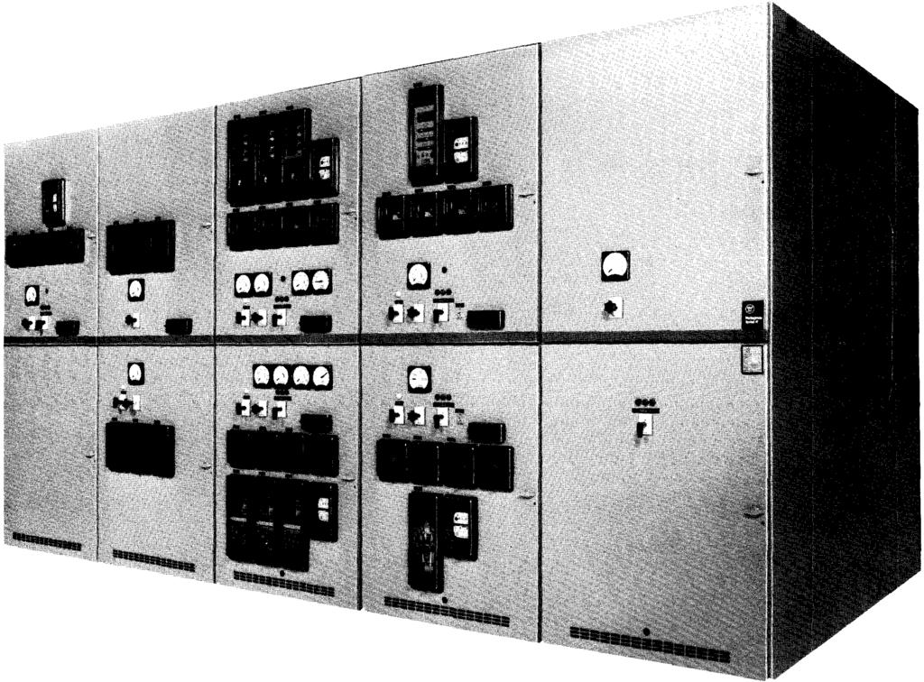
2 Page 2 Description and Application VacCiad-W Metal-Clad Switchgear is an integrated assembly of drawout vacuum circuit breakers, bus, and control devices coordinated electrically and mechanically for medium voltage circuit protection. The Metal-Clad integrity provides maximum circuit separation and safety. Included are isolated grounded metal compartments, complete insulation of all conductors and no live parts exposed by the opening of a door. It is typically used on circuits involving feeder circuits, transmission lines, distribution lines and motors. All major components are manufactured by Westinghouse, establishing one source of responsibility for the equipment and assuring high standards in quality, coordination, reliability and service. VacCiad-W Switchgear is available in voltage ratings of 4.76kV through 15kV and in nominal interrupting capacities of 250MVA(29kA), 350MVA(41 ka), 500MVA (18kA), 500MVA(41 ka), 750MVA(28kA), 1000MVA(37kA) and for indoor or outdoor applications. VacCiad-W Switchgear meets or exceeds ANSI C37.20, NEMA SG-5 and IEEE standards as they apply to Metal-Clad Switchgear. The circuit breaker also meets IEC standards. VacCiad-W Switchgear is designed to meet needs in six important areas: 1. Performance 2. Safety 3. Maintenance 4. Space Utilization 5. Application flexibility 6. Reliability Features C2) Vacuum Interrupter Current Transfer Conductor (See Pg. 17) The Westinghouse "Stiff-Flexible" design eliminates the need for a main conductor sliding contact and its costly maintenance. 0 Rails (See Pg. 16) The breaker and auxiliaries can be withdrawn on rails for inspection and maintenance without the need for a separate lifting device. 0 Front Mechanism (See Pg. 16) The stored energy mechanism is on the front of the breaker so the i nspection or maintenance can be done with the breaker on rails. 8 Horizontal Drawout Circuit (See Pg. 10) Type VCP-W breaker is a horizontal drawout design, which provides connect, test, and disconnect position. 0 Automatic Shutters (See Pg. 6) These steel shutters operate automatically when the circuit breaker is withdrawn, to protect workmen from accidental contact with the stationary primary contacts. 0 Main Bus System (See Pg. 8) The mam bus has fluidized bed, trackresistant epoxy insulation with plated joints and constant pressure washers. (f) Current Transformers (See Pg. 7) There is space for up to four current transformers per phase which are easily accessible from the front. 0 Primary and Secondary Contacts (See Pg. 10) All moving breaker contacts are selfaligning, have positive action, and are silver-plated. 0 Metal Compartment Barriers All compartments are enclosed by grounded metal Barriers Barriers are breaker Wheels (See Pg. 10) can be rolled on floor when removed from the Auxiliary Compartment Shutter (See Pg. 9) This shutter operates automatically when the auxiliary drawer is withdrawn to protect workmen from accidental contact with the stationary primary contacts. June,

3 June, 1987 Page 3
 @ Potential Transformers Potential transformers are drawer mounted for front accessibility and can be")
4 Page Cable Space Ample space is provided for cables, potheads, and other related components. Top or bottom cable entry is available. (See Space Utilization, Page 18, Application Flexibility, Page 19, and Maintenance, Page Potential Transformers Potential transformers are drawer mounted for front accessibility and can be completely withdrawn on rail extensions similar to the breaker. (See Maintenance, Page 15 and Performance Page Control Power Transformers Drawer mounting makes control power transformers accessible, they can be completely withdrawn the same as the potential transformer. (See Maintenance, Page 15 and Performance, Page 9) June,1987

5 Type VCP-W circuit breaker utilizing vacuum interrupters is available in ANSI and IEC ratings, plus several special ratings to provide maximum application flexibility. June, 1987 Page 5 Performance VacCiad-W Metal-Clad Switchgear offers a total design concept of cell, breaker and auxiliary equipment to meet the user needs. The design criteria was full compliance with ANSI, IEEE, NEMA and IEC standards. Conformance to industry standards assures a high level of performance and permits the specifier with ease and accuracy to define a level of performance developed by the industry for its needs. The applicable industry standards are: ANSI American National Standards Institute C Application guide for AC high voltage circuit breakers rated on a symmetrical current basis C Definitions for power switchgear C37.04 Rating structure for AC high voltage circuit breakers C37.06 Preferred ratings for AC high voltage circuit breakers as rated on a symmetrical current basis C37.07 Factors for reclosing service C37.09 Test Procedure for AC high voltage circuit breakers C37.11 Power circuit breaker control C37.20 Switchgear assemblies including metal-enclosed bus C37.24 Guide for evaluating the effect of solar radiation NEMA SG-4 SG-5 National Electrical Manufacturers Association Power Circuit s Power Switchgear Assemblies IEC 56.4 High Voltage AC Circuit s

6 Page 6 Performance, Continued Cell Features Steel shutters which are operated by the circuit breaker prevent accidental contact with live primary voltage parts, when the breaker is withdrawn. The photo shows the breaker compartment with the breaker and CT barrier removed showing the steel shutters. June, 1987

7 June, 1987 Page 7 Type VacCiad-W Mediu m Voltage Metal-Clad Switchgear Performance, Continued Cell Features The breaker compartment is shown with the automatic steel shutters forced into the open position, CT barrier removed. Primary insulating tubes and current transformer location are shown in this view. Primary stationary cell studs are also visible. Current Transformers Automatic Steel Shutters Primary Insulating Tubes The mechanism for levering the breaker is a unique cell mounted design. This levering system incorporates all the safety interlocks to render the breaker mechanically and electrically trip-free during the levering procedure. Further, the ground bus, visible on the left, is engaged by a ground contact on the breaker, so the breaker is grounded throughout the travel. Ground Stab Levering Mechanism Note: Shutters should be removed or forced into the open position only when the unit is deenergized. Shutters are shown in the open position for illustrative purposes only.

8 Page 8 Performance, Continued Cell Features Main Bus The main bus conductor is copper. All main bus has fluidized bed epoxy flame retardant track resistant insulation. The bolted bus connections are silver plated for positive contact and low resistance, with each joint insulated with easily installed boots. The main bus supports are shown below. June, 1987
9 Cl Performance, Continued Cell Features Auxiliary Compartments VacCiad-W design permits four auxiliary drawers in one vertical unit (only two shown here). A potential transformer drawer and a control transformer drawer are shown withdrawn on the rail extensions, which permits easy testing and fuse replacement. (0 All auxiliaries have automatic shutters. 0 The potential transformers meet all industry standards. Up to three potential transformers can be supplied per drawer. 0 The control power transformer drawer accommodating up to 15 kva single phase transformers with protective primary fuses is shown in the withdrawn position. June, 1987 Page 9

10 Page 10 Performance, Continued VCP-W The Type VCP-W circuit breaker, utilizing vacuum interrupters, is compact and light weight. The breaker includes six major components: 1. Vacuum interrupter pole units. 2. Stored energy mechanism enclosed in a metal housing. 3. Glass polyester supports for mounting the vacuum interrupter pole unit. 4. Primary disconnecting contacts. 5. Removable insulating barriers. 6. wheels permit breaker to be rolled on floor. Stored Energy --- Mechanism Primary Disconnecting Contacts Front View Removable Insulating Barner Vacuum Interrupter Pole Un1t Removable Insulating Barner June, 1987

11 Vacuum Interrupter Front Panel The steel breaker front panel is designed with the operator in mind. The breaker function indicators and controls are accessible and visible. They are: breaker-open/close, closing spring-charged/discharged, close and trip buttons, operation counter breaker latch, and manual spring charging access. June, 1987 Page 11 Type Vacclad-W Medium Voltage Metal-Clad Switchgear Vacuum Interrupter Pole Un1t Performance, Continued VCP-W poles are complete units that are easily accessible and removable. Since the support system is self-aligning, no special tools are required for replacement.
12 Page 12 Performance, Continued VCP-W Stored Energy Mechanism front panel removed exposing the stored energy mechanism. The stored energy mechanism is vertically mounted on the front of the breaker for easy access. There is one basic mechanism for all ratings and is of rugged fabricated steel construction for reliable operation and long life. It is available for either DC or AC operation. The stored energy mechanism is mechanically trip-free during breaker levering. Primary Disconnecting Contacts The primary disconnecting contacts are silver-plated copper-spring biased to maintain contact pressure. The primary contact design of the configuration shown is for 2000 amp continuous and below. The design has a long service life record, having been successfully used on previous designs of Westinghouse breakers. June, 1987

13 0 Metal Vapor Condensing Shield Insulating Envelope Separation High Current Arc _... _... _... Contacts - Bellows Shield Electrode Separation Page 13 Flexible Metallic Bellows Transient Recovery,. Voltage The current, voltage, and contact separation interrelationship is illustrated above. June, 1987 Performance, Continued VCP-W Vacuum Interrupter The Type VCP-W breaker utilizes vacuum interrupters for interruption and switching functions. Vacuum interrupters provide enclosed interrupter, small size and weight, interrupting time (high speed), long life, reduced maintenance, and environmental compatibility (low noise, no arc byproducts, and minimum mechanical shock). Arc interruption is simple and fast. The vacuum interrupter is shown. In the closed position normal current flows thru the interrupter. When a fault occurs and interruption is required, the contacts are quickly separated. An arc is drawn between the contact surfaces and is rapidly moved around the slotted electrode surface by self-induced magnetic effects, which prevents gross electrode erosion and the formation of hot spots on the surface. The arc burns in an ionized metal vapor, which continually leaves the contact area and condenses on the surrounding metal shield. At current zero, the arc extinguishes, vapor production ceases; and very rapid dispersion, cooling, recombination, and deionization of the metal vapor plasma, together with the fast condensation of metal vapor products, cause the vacuum condition to be quickly restored - hence the separated contacts withstand the transient recovery voltage.
14 Page 14 Safety Cell and Features VacCiad-W Metal-Clad Switchgear incorporates many outstanding safety features, which meet or exceed those required by metal-clad standards. Some of the outstanding features are: Safety Metal Shutters Steel shutters (breaker driven) rotate automatically into position to cover the insulating tubes to provide metal barriering of the cell stationary studs when the breaker is withdrawn from the connected position. Grounded Metal Barriers Grounded metal barriers separate all compartments, completely enclosing major parts of the primary circuit, main bus, breaker, potential transformers and control power transformers. These barriers must be removed to gain access to any energized compartment. All control devices are separated from high-voltage circuits by grounded metal barriers. Levering System Operators and equipment are both protected by a variety of interlocks on the breaker assembly. 1. A breaker cannot be levered unless the interrupter contacts are open. 2. is mechanically trip-free during levering. 3. Closed door levering is avai lable if specified. Levering Crank Operation 4. Discharge of closing spring as breaker is withdrawn from the cell. 5. A latch secures the breaker in the connected, disconnected or test position. VCP-W Cell (CT Barrier Removed) Cell Mounted Levering System is grounded during levering and in the connected position. Front panel - steel barrier. Metal Shutters Coding plates provide that only correct breaker rating can be installed in cell. June, 1987

15 Maintenance Cell Features Auxiliary Equipment Control power transformers with currentlimiting fuses and potential transformers are drawer-mounted in enclosed compartments. These compartments are automatically disconnected and grounded, when the drawer is withdrawn from the compartment on rails. Auxiliaries have automatic glass polyester shutters which are operated by the drawer. Current Transformers Current transformers are accessible from the front. This design and front accessibility permit adding or changing transformers when the unit is deenergized without breaking high voltage connections and primary insulation. June, 1987 Page 15 Note: Shutters should be removed or forced into the open position only when the unit is de energized. Shutters are shown in the open posi tion for illustrative purposes only. Cable Accessibility The design provides adequate space for cable termination in the two high arrangement with cable for each circuit separated by metal barriers. Barriers are easily removed as shown.

16 Page 16 Maintenance, Continued Features Normal inspection - can be withdrawn on extendable rails for easy access without requiring separate lifting device. Mechanical inspection - Easy inspection and accessibility is afforded by the front mounted stored-energy mechanism. The same basis mechanism is used in all ratings, which requires a minimum investment in spare parts. June, 1987


17 Maintenance, Continued Features June, 1987 Page 17 Vacuum Interrupter Current Transfer Conductor The stiff-flexible current transfer from the vacuum interrupter moving stem to the breaker main conductor is a non-sliding design- thus eliminating the maintenance required with sliding type transfer arrangements. Reduced Maintenance Due to the inherent long life characteristics of the vacuum interrupter and the reliable stored-energy mechanism, the type VCP-W breaker requires minimum maintenance. Vacuum interrupter centact wear indicator. Clearly visible, wear-gap (contact erosion) indicators require only an occasional check.
18 Page 18 Space Utilization VacCiad-W Switchgear has been designed for efficient use of space. In many situations, total required floor space may be reduced by as much as 50% compared to conventional switchgear. The rail extension feature for both the circuit breaker and auxiliaries, enable these draw-out devices to be withdrawn for inspection and maintenance without the use of unique lifting devices needed with other designs. Conventional Switchgear VacCiad-W June, 1987

19 Application Flexibility VacCiad-W Switchgear has the flexibility to meet most installation conditions or requirements. One-high combinations can be provided. Modular construction provides for ease of assembly, initial flexibility of installation, and future expansion or modification. Rear compartments are designed for either top or bottom entry of cable or bus runs. Provisions for four current transformers per phase. Provisions for as many as four sets of drawout auxiliaries in one vertical section. Indoor and outdoor. Complete ANSI rating range available, plus several special ratings. IEC breaker ratings. Reliability Reliability was the fundamental consideration of engineering design, material selection, use and design of components, manufacturing, test procedures, shipping and handling to assure the user of on-site reliability. Design/Proof Tests VacCiad-W Metal-Clad Switchgear meets applicable ANSI, IEEE, NEMA and IEC standards. The design criteria dictated that all tests demonstrate performance above the requirements of the standards. The ANSI test series is basic test criteria and includes interruption, BIL, dielectric, continuous current, mechanical life, and thermal and environmental conditions. The design/proof testing of VacCiad-W Switchgear is the most extensive ever performed by Westinghouse, which has always maintained the highest test standards for its metal-clad equipment. Production Tests Circuit Each breaker draw-out unit is checked for alignment with a master cell fixture that verifies all interfaces and interchangeability. All circuit breakers are operated over the range of minimum to maximum control voltage. Interrupter contact gap is factory set. One-minute dielectric test is performed on each breaker per ANSI Standards. Final inspection and quality check. June, 1987 Housing Page 19 Master breaker fixture is inserted into each breaker cell to ensure alignment. One-minute dielectric test per ANSI Standards is applied to both primary and secondary circuits. Operation of wiring, relays, and other devices is verified by an operational sequence test. Final inspection and quality check. Supplemental Device Ground and Test Device The ground and test device is a drawout element that may be inserted into a Metal-Clad Switchgear housing in place of a circuit breaker. It provides access to the primary circuits to permit the temporary connection of grounds or testing equipment to the high voltage circuits. High potential testing of cable or phase checking of circuits are typical tests which may be performed. The devices are insulated to suit the voltage rating of the switchgear and will carry required levels of short circuit current. Manual ground and test devices are available. These devices include six studs for connection to primary circuits. The manual device selection and grounding are accomplished by cable connection. Notice Before using ground and test devices it is recommended that each user develop detailed operating procedures consistent with safe operating practices. Only qualified personnel should be authorized to use ground and test devices. Standard Accessories 1 - Test Jumper 1 - Levering Crank 1 - Maintenance Tool 1 - Lifting Yoke 1 - Set Rail Clamps 1 - Set of Extension Rails 1 - Transport Dolly (Optional) 1 - Portable Lifter (Optional) 1 -Test Cabinet (Optional) Universal Lifting Yoke For User's Lifting Device Optional Portable lifter
20 .. Page 20 Weights and Dimensions Typical Weights (Pounds) Assemblies (Less s) Type ofgl Vertical Section BiB B/A or AlB AlA s Type of 50 VCP-W VCP-W VCP-W VCP-W VCP-W VCP-W 1000 I 115" Main Bus Rating Amps Indoor Aisle-Less Sheltered-Aisle Including Aisle Current Rating, Amps Single Row Double Row oo 2ooo 1 3ooo Approx. Wt., Lbs I l " " Outdoor A1sle-Less Outdoor Sheltered Aisle Single Row 121"...,, 71.5"----fo< " " "11 J " Dimensions, Inches Note: Dimensions not to be used for construction. These shown are for reference only. Consult Westinghouse for exact dimensions. Cl PH Indoor " " see Page 93 for Available Configurations Outdoor Sheltered Aisle Double Row June, 1987
21 Typical Units 36" Wide Typical / Vertical Section /2000/3000 Amp. main bus 2-Type VCP-W breakers 1200/2000 Amp. in 2 - high configuration 4 - Current transformers per phase ANSI ratings. - Potheads 1/C or 3/C - Surge suppressors, if desired. - Zero sequence current transformer (ZST) 36" Wide Typical Auxiliary/ Vertical Section /2000/3000 Amp. main bus 1 -Type VCP breaker 1200/2000 Amp. in lower position 1 - Drawout potential transformer drawer 2 - L-L with fuses 3 - L-G with fuses - Drawout control power transformer drawer CPT - 15 kva max. - single phase -Zero sequence current transformers (ZST) - Surge suppressors, if desired. June, 1987 r I 95" Page 21 Fixed CPT " ----.! 36" Wide Typical Auxiliary/Auxiliary Vertical Section /2000/3000 Amp. main bus. Illustrating maximum utilization of auxiliary compartment with 4-high drawout auxiliaries and fixed mounted control power transformer. Available Configurations 1200 Amp 1200 Amp Drawout Auxiliary 1200 Amp Drawout Auxiliary Drawout Auxiliary 3000 Amp Drawout Auxiliary 1200 Amp 2000 Amp 2000 Amp Drawout Auxiliary 2000 Amp 1200 Amp 1200 Amp Drawout Auxiliary Drawout Auxiliary 2000 Amp Vented Auxiliary Comp. (Non-0.0.) 3000 Amp
22 Page 22 Application Table 1: Available Types Rated on Symmetrical Current Rating Basis, per ANSI Standards Identification Rated Values Related Required Nominal Nominal Voltage Insulation Level Current Rated Rated Rated Current Values Voltage 3-Phase Inter- Perm is- Rated Rated Rated Withstand Rated Rated Max. Maxi- 3 Sec. Closing Class MVA rupting Max. Voltage Test Voltage Cantin- Short sible Voltage mum Short- and Class Time Tripping Divided Voltage Range uous Circuit Sym. Time Latching Delay By K Factor Current Current Inter- Current Capability at (at rupting Carrying (Momentary) 60 rated Capa- Capability Gl Hz Max. bility Kv) K Times Rated 1.6 K Times Short-Circuit Rated Short- 0 Low Current Circuit Fre- Impulse Kl Current Circuit E K quency I E/K Kv MVA Type Class Class Kv rms Kv rms Kv Crest Amperes KA rms Cycles Sec. Kv rms KA rms KA rms KA rms VCP-W Vacuum Circuit 50 VCP-W ' Gl VCP-W ! VCP-W VCP-W iy 78 I Gl VCP-W ' I Gl VCP-W I Table 2: Available Types Rated on Symmetrical Current Rating Basis per IEC Standards Circuit Voltage Insulation Level Rated Rated Class, kv Continuous Interrupting Type I I Momentary Current, ka Current, Current, Low Impulse ' 3 Sec. Peak Amps. ka Freq., Withstand I kv kv 50 VCP-W VCP-W VCP-W VCP-W VCP-W VCP-W 1000 CD Non-Standard s with High Momentary Rating available for Special Applications. For 3 phase and line to line faults, the sym interrupting capability at a Kv operating voltage h (Rated Short-Circuit Current) But not to exceed Kl. Single line to ground fault capability at a Kv operating voltage E Kv (Rated Short-CirCUit Current) But not to exceed Kl. "Mle above apply on predominately inductive or resistive 3-phase circuits with normal-frequency line to line recovery voltage equal to the operating voltage ' 25 i ! '25 I I For Reclosing Service, the Sym. Interrupting Capability and other related capabilities are modified by the reclosing capability factor obtained from the following formula: R(%) 100 -C[ 15- T, 15-T, (n-2) 6 + _1_5_ i5 + Where C KA Sym. Interrupting Capability at the Operating Voltage but not less than 18. n = Total No. of Openings. T,, T2, etc. '-' Time interval in seconds except use 15 for time intervals longer than 15 sec. Note: Reclosing Service with the standard duty cycle 0 t- 15s + CO. Does not require breaker capabilities modified since the reclosing capability factor R = 100%. 64 Tripping may be delayed beyond the rated permissible tripping delay at lower values of current in accordance with the following formula: T I d I [KI(K Times Rated Short Circuit Current)] ' secon s = Y - Short-Circuit Current Through The aggregate tripping delay on all operations within any 30 minute period must not exceed the time obtained from the above formula. Standard duty cycle: 0-3 min. -CO-3 min. -CO. Not IEC recognized. June, 1987

23 June, 1987 Page 23
24 Page 24 Westinghouse Electric Corporation Distribution and Control Business Unit Assemblies Division Greenwood, SC June, 1987
25

26 Page 2 Description and Application VacCiad-W Metal-Clad Switchgear is an integrated assembly of drawout vacuum circuit breakers, bus, and control devices coordinated electrically and mechanically for medium voltage circuit protection. The Metal-Clad integrity provides maximum circuit separation and safety. Included are isolated grounded metal compartments, complete insulation of all conductors and no live parts exposed by the opening of a door. It is typically used on circuits involving feeder circuits, transmission lines, distribution lines and motors. All major components are manufactured by Westinghouse, establishing one source of responsibility for the equipment and assuring high standards in quality, coordination, reliability and service. VacCiad-W Switchgear is available in voltage ratings of 4.76kV through 15kV and in nominal interrupting capacities of 250MVA(29kA), 350MVA(41 ka), 500MVA (18kA), 500MVA(33kA), 750MVA(28kA), 1000MVA(37kA) and for indoor or outdoor applications. VacCiad-W Switchgear meets or exceeds ANSI C37.20, NEMA SG-5 and IEEE standards as they apply to Metal-Clad Switchgear. The circuit breaker also meets IEC standards. VacCiad-W Switchgear is designed to meet needs in six important areas: 1. Performance 2. Safety 3. Maintenance 4. Space Utilization 5. Application flexibility 6. Reliability Features 0 Vacuum Interrupter Current Transfer Conductor (See Pg. 17) The Westinghouse "Stiff-Flexible" design eliminates the need for a main conductor sliding contact and its costly maintenance. 0 Rails (See Pg. 16) The breaker and auxiliaries can be withdrawn on rails for inspection and maintenance without the need for a separate lifting device. 0 Front Mechanism (See Pg. 16) The stored energy mechanism is on the front of the breaker so the inspection or maintenance can be done with the breaker on rails. 8 Horizontal Drawout Circuit (See Pg. 10) Type VCP-W breaker is a horizontal drawout design, which provides connect, test, and disconnect position. (D Automatic Shutters (See Pg. 6) These steel shutters operate automatically when the circuit breaker is withdrawn, to protect workmen from accidental contact with the stationary primary contacts. (D Main Bus System (See Pg. 8) The main bus has fluidized bed, trackresistant epoxy insulation with plated joints and constant pressure washers. (}) Current Transformers (See Pg. 7) There is space for up to four current transformers per phase which are easily accessible from the front. (D Primary and Secondary Contacts (See Pg. 10) All moving breaker contacts are selfaligning, have positive action, and are silver-plated. 0 Metal Compartment Barriers All compartments are enclosed by grounded metal Barriers Barriers are breaker Wheels (See Pg. 10) can be rolled on floor when removed from the Auxiliary Compartment Shutter (See Pg. 9) This shutter operates automatically when the auxiliary drawer is withdrawn to protect workmen from accidental contact with the stationary primary contacts. January, 1989

27 January, 1989 Page 3
28 Page Cable Space Ample space is provided for cables, potheads, and other related components. Top or bottom cable entry is available. (See Space Utilization, Page 18, Application Flexibility, Page 19, and Maintenance, Page Voltage Transformers Voltage transformers are drawer mounted for front accessibility and can be completely withdrawn on rail extensions similar to the breaker. (See Maintenance, Page 15 and Performance Page Control Power Transformers Drawer mounting makes control power transformers accessible, they can be completely withdrawn the same as the potential transformer. (See Maintenance, Page 15 and Performance, Page 9) January, 1989
29 Type VCP-W circuit breaker utilizing vacuum interrupters is available in ANSI and IEC ratings, plus several special ratings to provide maximum application flexibility. January, 1989 Page 5 Performance VacCiad-W Metal-Clad Switchgear offers a total design concept of cell, breaker and auxiliary equipment to meet the user needs. The design criteria was full compliance with ANSI, IEEE, NEMA and IEC standards. Conformance to industry standards assures a high level of performance and permits the specifier with ease and accuracy to define a level of performance developed by the industry for its needs. The applicable industry standards are: ANSI American National Standards Institute C Application guide for AC high voltage circuit breakers rated on a symmetrical current basis C Definitions for power switchgear C37.04 Rating structure for AC high voltage circuit breakers C37.06 Preferred ratings for AC high voltage circuit breakers as rated on a symmetrical current basis C37.07 Factors for reclosing service C37.09 Test Procedure for AC high voltage circuit breakers C37.11 Power circuit breaker control C Metal-Clad and Station-Cubicle Switchgear C37.24 Guide for evaluating the effect of solar radiation NEMA SG-4 SG-5 IEC 56 National Electrical Manufacturers Association Power Circuit s Power Switchgear Assemblies High Voltage AC Circuit s

30 Page 6 Performance, Continued Cell Features Steel shutters which are operated by the circuit breaker prevent accidental contact with live primary voltage parts, when the breaker is withdrawn. The photo shows the breaker compartment with the breaker and CT barrier removed showing the steel shutters. Cl January, 1989

31 January, 1989 Page 7 Performance, Continued Cell Features The breaker compartment is shown with the automatic steel shutters forced into the open position, CT barrier removed. Primary insulating tubes and current transformer location are shown in this view. Primary stationary cell studs are also visible. Current Transformers Automatic Steel Shutters Primary Insulating Tubes The mechanism for levering the breaker is a unique cell mounted design. This levering system incorporates all the safety interlocks to render the breaker mechanically and electrically trip-free during the levering procedure. Further, the ground bus, visible on the left, is engaged by a ground contact on the breaker, so the breaker is grounded throughout the travel. Ground Stab Levering Mechanism Note: Shutters should be removed or forced into the open position only when the unit is deenergized. Shutters are shown in the open position for illustrative purposes only.
32 Page 8 Performance, Continued Cell Features Main Bus The main bus conductor is copper. All main bus has fluidized bed epoxy flame retardant track resistant insulation. The bolted bus connections are silver plated for positive contact and low resistance, with each joint insulated with easily installed boots. The main bus supports are shown below. January, 1989
 All auxiliaries have automatic shutters.")
33 Performance, Continued Cell Features Auxiliary Compartments VacCiad-W design permits four auxiliary drawers in one vertical unit (only two shown here). A voltage transformer drawer and a control transformer drawer are shown withdrawn on the rail extensions, which permits easy testing and fuse replacement. (2) All auxiliaries have automatic shutters. 0 The voltage transformers meet all industry standards. Up to three voltage transformers can be supplied per drawer. 0 The control power transformer drawer accommodating up to 15 kva single phase transformers with protective primary fuses is shown in the withdrawn position. January, 1989 Page 9


34 Page 10 Performance, Continued VCP-W The Type VCP-W circuit breaker, utilizing vacuum interrupters, is compact and light weight. The breaker includes six major components: 1. Vacuum interrupter pole units. 2. Stored energy mechanism enclosed in a metal housing. 3. Glass polyester supports for mounting the vacuum interrupter pole unit. 4. Primary disconnecting contacts. 5. Removable insulating barriers. 6. wheels permit breaker to be rolled on floor. Stored Energy --- Mechanism Pnmary Disconnecting Contacts Wheel Front View Removable Insulating Bamer Rear View Vacuum Interrupter Pole Un1t Removable lnsulattng Barner January, 1989
35 Vacuum Interrupter Front Panel The steel breaker front panel is designed with the operator in mind. The breaker function indicators and controls are accessible and visible. They are: breaker-open/close, closing spring-charged/discharged, close and trip buttons, operation counter breaker latch, and manual spring charging access. January, 1989 Page 11 Vacuum Interrupter Pole Un1t Performance, Continued VCP-W poles are complete units that are easily accessible and removable. Since the support system is self-aligning, no special tools are required for replacement.

36 Page 12 Performance, Continued VCP-W Stored Energy Mechanism front panel removed exposing the stored energy mechanism. The stored energy mechanism is vertically mounted on the front of the breaker for easy access. There is one basic mechanism for all ratings and is of rugged fabricated steel construction for reliable operation and long life. It is available for either DC or AC operation. The stored energy mechanism is mechanically trip-free during breaker levering. Primary Disconnecting Contacts The primary disconnecting contacts are silver-plated copper-spring biased to maintain contact pressure. The primary contact design of the configuration shown is for 2000 amp continuous and below. The design has a long service life record, having been successfully used on previous designs of Westinghouse breakers. January, 1989
37 0 Metal Vapor Condensing Shield Insulating Envelope Separation High Current Arc Contacts - Bellows Shield Page 13 Flexible Metallic Bellows Moving Stem _...- Electrode Current Zero Separation Arc Extinction / Transient Recovery Voltage The current, voltage, and contact separation interrelationship is illustrated above. January, 1989 Performance, Continued VCP-W Vacuum Interrupter The Type VCP-W breaker utilizes vacuum interrupters for interruption and switching functions. Vacuum interrupters provide enclosed interrupter, small size and weight, interrupting time (high speed). long life, reduced maintenance, and environmental compatibility (low noise, no arc byproducts, and minimum mechanical shock). Arc interruption is simple and fast. The vacuum interrupter is shown. In the closed position normal current flows thru the interrupter. When a fault occurs and interruption is required, the contacts are quickly separated. An arc is drawn between the contact surfaces and is rapidly moved around the slotted electrode surface by self-induced magnetic effects, which prevents gross electrode erosion and the formation of hot spots on the surface. The arc burns in an ionized metal vapor, which continually leaves the contact area and condenses on the surrounding metal shield. At current zero, the arc extinguishes, vapor production ceases; and very rapid dispersion, cooling, recombination, and deionization of the metal vapor plasma, together with the fast condensation of metal vapor products, cause the vacuum condition to be quickly restored- hence the separated contacts withstand the transient recovery voltage.
 rotate automatically into position to cover the insulating tubes to provide metal barriering of the cell")
38 Page 14 Safety Cell and Features VacCiad-W Metal-Clad Switchgear incorporates many outstanding safety features, which meet or exceed those required by metal-clad standards. Some of the outstanding features are: Safety Metal Shutters Steel shutters (breaker driven) rotate automatically into position to cover the insulating tubes to provide metal barriering of the cell stationary studs when the breaker is withdrawn from the connected position. Grounded Metal Barriers Grounded metal barriers separate all compartments, completely enclosing major parts of the primary circuit, main bus, breaker, potential transformers and control power transformers. These barriers must be removed to gain access to any energized compartment. All control devices are separated from high-voltage circuits by grounded metal barriers. Levering System Operators and equipment are both protected by a variety of interlocks on the breaker assembly. 1. A breaker cannot be levered unless the interrupter contacts are open. 2. is mechanically trip-free during levering. 3. Closed door levering is available if specified. Levering Crank Operation 4. Discharge of closing spring as breaker is withdrawn from the cell. 5. A latch secures the breaker in the connected, disconnected or test position. VCP-W Cell (CT Barrier Removed) Cell Mounted Levering System is grounded during levering and in the connected position. Front panel- steel barrier. Metal Shutters Coding plates provide that only correct breaker rating can be installed in cell. January, 1989
39 Maintenance Cell Features Auxiliary Equipment Control power transformers with currentlimiting fuses and voltage transformers are drawer-mounted in enclosed compartments. These compartments are automatically disconnected and grounded, when the drawer is withdrawn from the compartment on rails. Auxiliaries have automatic glass polyester shutters which are operated by the drawer. Current Transformers Current transformers are accessible from the front. This design and front accessibility permit adding or changing transformers when the unit is deenergized without breaking high voltage connections and primary insulation. January, 1989 Page 15 A Note: Shutters should be removed or forced into the open position only when the unit is deenergized. Shutters are shown in the open position for illustrative purposes only. Cable Accessibility The design provides adequate space for cable termination in the two high arrangement with cable for each circuit separated by metal barriers. Barriers are easily removed as shown.

40 Page 16 Maintenance, Continued Features Normal inspection- can be withdrawn on extendable rails for easy access without requiring separate lifting device. Mechanical inspection- Easy inspection and accessibility is afforded by the front mounted stored-energy mechanism. The same basis mechanism is used in all ratings, which requires a minimum investment in spare parts. January, 1989
41 Maintenance, Continued Features January, 1989 Page 17 Vacuum Interrupter Current Transfer Conductor The stiff-flexible current transfer from the vacuum interrupter moving stem to the breaker main conductor is a non-sliding design - thus eliminating the maintenance required with sliding type transfer arrangements. Reduced Maintenance Due to the inherent long life characteristics of the vacuum interrupter and the reliable stored-energy mechanism, the type VCP-W breaker requires minimum maintenance. Vacuum interrupter contact wear indicator. Clearly visible, wear-gap (contact erosion) indicators require only an occasional check.
42 Page 18 Space Utilization VacCiad-W Switchgear has been designed for efficient use of space. In many situations, total required floor space may be reduced by as much as 50% compared to conventional switchgear. The rail extension feature for both the circuit breaker and auxiliaries, enable these draw-out devices to be withdrawn for inspection and maintenance without the use of unique lifting devices needed with other designs. Conventional Switchgear VacCiad-W January, 1989
43 Application Flexibility VacCiad-W Switchgear has the flexibility to meet most installation conditions or requirements. One-high combinations can be provided. Modular construction provides for ease of assembly, initial flexibility of installation, and future expansion or modification. Rear compartments are designed for either top or bottom entry of cable or bus runs. Provisions for four current transformers per phase. Provisions for as many as four sets of drawout auxiliaries in one vertical section. Indoor and outdoor. Complete ANSI rating range available, plus several special ratings. IEC breaker ratings. Reliability Reliability was the fundamental consideration of engineering design, material selection, use and design of components, manufacturing, test procedures, shipping and handling to assure the user of on-site reliability. Design/Proof Tests VacCiad-W Metal-Clad Switchgear meets applicable ANSI, IEEE, NEMA and IEC standards. The design criteria dictated that all tests demonstrate performance above the requirements of the standards. The ANSI test series is basic test criteria and includes interruption, BIL, dielectric, continuous current, mechanical life, and thermal and environmental conditions. The design/proof testing of VacCiad-W Switchgear is the most extensive ever performed by Westinghouse, which has always maintained the highest test standards for its metal-clad equipment. Production Tests Circuit Each breaker draw-out unit is checked for alignment with a master cell fixture that verifies all interfaces and interchangeability. All circuit breakers are operated over the range of minimum to maximum control voltage. Interrupter contact gap is factory set. One-minute dielectric test is performed on each breaker per ANSI Standards. Final inspection and quality check. January, 1989 Housing Page 19 Master breaker fixture is inserted into each breaker cell to ensure alignment. One-minute dielectric test per ANSI Standards is applied to both primary and secondary circuits. Operation of wiring, relays, and other devices is verified by an operational sequence test. Final inspection and quality check. Supplemental Device Ground and Test Device The ground and test device is a drawout element that may be inserted into a Metal-Clad Switchgear housing in place of a circuit breaker. It provides access to the primary circuits to permit the temporary connection of grounds or testing equipment to the high voltage circuits. High potential testing of cable or phase checking of circuits are typical tests which may be performed. The devices are insulated to suit the voltage rating of the switchgear and will carry required levels of short circuit current. Both manual and electrically operated ground and test devices are available. These devices include six studs for connection to primary circuits. On the manual device, selection and grounding are accomplished by cable connection. On the electrically operated device, a two position switch provides for correct selection of the proper primary circuit. Grounding is accomplished by an electrically operated stored energy ground switch. Notice Before using ground and test devices it is recommended that each user develop detailed operating procedures consistent with safe operating practices. Only qualified personnel should be authorized to use ground and test devices. Standard Accessories 1 - Test Jumper 1 - Levering Crank 1 - Maintenance Tool 1 - Lifting Yoke 1 - Set Rail Clamps 2-Sets of Rails 1 - Transport Dolly (Optional) 1 - Portable Lifter (Optional) 1 - Test Cabinet (Optional) Universal lifting Yoke For User's lifting Device Optional Portable lifter
44 ... Page 20 Weights and Dimensions Typical Weights (Pounds) Assemblies (Less s) Type ofcd Vertical Section BIB B;A or AlB AlA s Type of 50 VCP-W VCP-W VCP-W VCP-W VCP-W VCP-W DO DO Term. Blocks Main Bus Rating Amps Indoor I Aisle-Less Sheltered-Aisle Including Aisle Single Row Outdoor Sheltered Aisle Single Row T Outdoor Aisle-Less Aisle Door Double Row if4t---- s ;._jjj Dimensions, Inches DO DO Aisle Door Term. Blocks I : II I Note: Dimensions not to be used for construction. These shown are for reference only. Consult Westinghouse for exact dimensions DO DO DO DO Term. Blocks DO DO DO DO Term. Blocks Indoor f4.: ='-= Outdoor Sheltered Aisle Double Row _J -1 I 95.0 I I l r--3.5 T I January, 1989,,.
45 Cl Typical Units DO DO.DOL 'DO b,-j::::=: :ks ===:::r-j f " Wide Typical / Vertical Section /2000/3000 Amp. main bus 2-Type VCP-W breakers 1200/2000 Amp. in 2 - high configuration 4-Current transformers per phase ANSI ratings. - Potheads 1/C or 3/C - Lightning arresters, if desired. - Zero sequence current transformer (ZST),-----,--c--.---cc---r Term. Blocks 36" Wide Typical Auxiliary/ Vertical Section ' /2000/3000 Amp. main bus 1 -Type VCP breaker 1200/2000 Amp. in lower position 1 - Drawout voltage transformer drawer 2 - L-L with fuses 3 - L-G with fuses - Drawout control power transformer drawer CPT - 15 kva max. - single phase - Zero sequence current transformers (ZST) - Lightning arrestors, if desired. January, 1989 Page Joo; 36" Wide Typical Auxiliary/Auxiliary Vertical Section /2000/3000 Amp. main bus. Illustrating maximum utilization of auxiliary compartment with 4 - high drawout auxiliaries and fixed mounted control power transformer. Available Configurations 1200 Amp 1200 Amp Drawout Auxiliary 1200 Amp Drawout Auxiliary Drawout Auxiliary 3000 A Vent Area Drawout Auxiliary 1200 Amp 2000 Amp 2000 Amp Orawout Auxiliary 2000 Amp 1200 Amp 1200 Amp Orawout Auxiliary Orawout Auxiliary 2000 Amp Vented Auxihary Camp. INon-0.0.) 3000 Amp
46 Page 22 Type VacClad-W Medium Voltage Metal-Clad Switchgear Application Table 1: Available VCP-W Vacuum Circuit Types Rated on Symmetrical Current Rating Basis, per ANSI Standards Identification Circuit I Rated Values Nominal I Nominal Voltage Insulation Level Current Rated 1 nte r- Class MVA Max. Voltage Test Voltage Cantin- Short Class Voltage Range ,--" i uous Circuit rupting Time 1 Factor Current Current at (at 60 rated Hz Max. 1 kv) Vo I tag e kv MVA 3-Ph ase 1-' :_ Rated -,-R - at_e_d - _:: ::: V = T Y.,Pe _C ass C _ Ia s _ s. k_v rms _ I I 50 VCP-W VCP-W 350 i I 4.16 CD Non-Standard s with High Momentary Rating available for Special Applications. For 3 phase and line to line faults, the sym interrupting capability at an operating voltage, Vo v = Vo (Rated Short-Ctrcutt.. c urrent) But not to exceed Kl. Single line to ground fault capability at an operating voltage, Vo v Yo (Rated Short-C rcu1t Current) But not to exceed Kl. The above apply on predominately inductive or resistive 3-phase circuits with normal-frequency line to line recovery voltage equal to the operating voltage. K i _R_a_te_d Low Fre- Impulse I@ quency W_i_th_s_t_a n-d- - 1 "-'- -'- -Ratē d-- -, - - Rā tēd Rated Permissible Tripping Delay kv rms kv Crest Amperes ka rms Cycles For Reclosing Service, the Sym. Interrupting Capability and other related capabilities are modified by the reclosing capability factor obtained from the following formula: RI%) 100-C [ I 15-T, 15-Tz n- 21 ] 6 + _1_5_ Where C KA Sym. Interrupting Capability at the Operating Voltage but not less than 18. n Total No. of Openings. T1, T2, etc. = Time interval in seconds except use 15 for time intervals longer than 15 sec. Note: Reclosing Service with the standard duty cycle s + CO. Does not require breaker capabilities modified since the reclosing capability factor R = 100%. y Related Required Capabilities@ Rated Current Values Max. Maximum Short 3 Sec. Closing Voltage Divided I and Sym. Time 1 Latching By K Interrupting Current i Capability Capability Carrying Capability (Momentary) CB K Times Rated Short-Circuit 1 I, Current Kl V.K kv rms! ka rms ka rms 36 Cl 1.6 K Times 2.7K Times Rated Short- Rated Short-, Circuit Circuit Current Tripping may be delayed beyond the rated permissible tripping delay at lower values of current in accordance with the following formula: T I secon d [ ] I y KI (K Times Rated Short-Circuit Current) z 5 Short-Circuit Current Through The aggregate tripping delay on all operations within any 30 minute period must not exceed the time obtained from the above formula. Included for reference only. Preferred rating. January, 1989
47 8 Page 23 Table 2: Available VCP-W Vacuum Circuit Types Rated on Symmetrical Current Rating Basis per IEC Standards I Voltage, W1_thstand Voltages I Normal Short Circuit Short Time I i 1 U (3 Sec.) 1 m--;;;:- Lightning- I Type ' Withstand I Short Circu1t Making Current (Peak) 36 VCP-W Ot 40t ----t I Cur - ent ka( J so vcp-w 32= 3.6 I 0ot t ns VCP-W 40 t 3.6 lot 40t - [ I r- I :w t VCP-W vcp w VCP-W 40 l_ Current I rea king -+1 kv rrt1s_ I e ncy : p :::: t I -- ; : ,,-- ""' 7.2 J 20t - b ---" " ' ----j ' """--- e 60t I ' : I _j '" ent, 1 4() VCP-W t 75t 630 i vcp:w i2--! -, 120 VCP-W 40 fl2 1 28t 175 VCP-W VCP-W 32 _E 175 VCP-W 40 l ; I 2-- '"' '"' 1 ; :: 1 31.s - _ 75t ' 40 -, , _ L 95 1 twithstand voltage capabilities exceed these values. Contact your local Westinghouse representative if you require higher values. G) In the IEC rating structure per IEC 56 and IEC 694, there is no "Voltage range factor 'K'". Therefore the 175, VCP-W 25 is rated at 25 ka at 17.5 kv, and also 25 ka at 13.2 kv. There is no in crease in short circuit current rating to go along with the lower applied voltage level. The rated operating sequence is 0-3m-C0-3m-CO. However these breaker ratings are also available for rapid auto-reclosing service with the 0-0.3s-C0-3m-CO operating sequence. January, fa - j_ - - L 1 25 I:- - [_ ra X I" ka Crest I t I,::- i ' o _]_
Medium Voltage Standby non-paralleling Control GUIDE FORM SPECIFICATION
 Medium Voltage Standby non-paralleling Control 1. GENERAL GUIDE FORM SPECIFICATION A. The requirements of the contract, Division 1, and part 16 apply to work in this section. 1.01 SECTIONS INCLUDE A. Medium
Medium Voltage Equipment 5-15 kv GM-SG and 38 kv GM38 Metal-Clad Switchgear General
 13 SWITCHGEAR Medium Voltage Equipment -1 kv GM-SG and 38 kv GM38 Metal-Clad Switchgear General Overview Features Siemens, 7, 1 and 38kV class medium voltage, one- or two-high vacuum circuit breaker switchgear
SIEMENS-ALLIS. Medium Voltage. Metalclad Switchgear. www. ElectricalPartManuals. com
 SEMENS-ALLS Medium Voltage Metalclad Switchgear Page 2 Typical Arrangements Auxiliary Cell Over 2000A Breaker Cell A Breaker Cell Over A Breaker Cell --!1 A Breaker Cell Over 2000A Breaker Cell Auxiliary
Westinghouse Electric Corporation Switchgear Division East Pittsburgh, PA 15112, U.S.A.
 .. July 1982 New Information Mailed to: E, 0, C/1942/DB. a D.. 0...l rj - Westinghouse Electric Corporation Switchgear Division East Pittsburgh, PA 15112, U.S.A. Up to 1000 MVA(37 KA) At 15000Volts Up
Metal-Enclosed Switches. Medium Voltage. Medium Voltage Metal-Enclosed Switches Contents
 January 2003 Vol. 1, Ref. No. [1011] -1 Medium Voltage Metal-Enclosed Switches Contents Description Page MVS................................... -2 and Breaker MSB........................ -3 Metal-Enclosed
Descriptive bulletin. Medium voltage load interrupter switchgear Reliable, low maintenance and economical for distribution applications
 Descriptive bulletin Medium voltage load interrupter switchgear Reliable, low maintenance and economical for distribution applications General overview Reliable, low maintenance and economical Load Interrupter
Medium Voltage Metal-Enclosed Switches
 Medium Voltage Metal-Enclosed Switches Outdoor Medium Voltage Switch.1 Medium Voltage Switch MVS Product Description............................................. 2 Application Description..........................................
Power/Vac OEM Express Switchgear
 g Power/Vac OEM Express Switchgear Metalclad Switchgear 4.16kV-250 MVA through 13.8kV-1500 MVA DEA-275 FULLY ASSEMBLED MECHANICALLY COMPLETE SWITCHGEAR WITHOUT DEVICES AND WIRE. POWER/VAC OEM EXPRESS SWITCHGEAR
5kV to 38kV, 630 Amp to 4000 Amp Indoor or Outdoor Application
 The most advanced Arc-Resistant Switchgear, designed and built to provide maximum safety in the event of an Internal Arcing Fault. 5kV to 38kV, 630 Amp to 4000 Amp Indoor or Outdoor Application Page 1
Medium Voltage Metal-Enclosed Switches
 Medium Voltage Metal-Enclosed Switches Outdoor Medium Voltage Switch.1 Introduction Product Selection Guide....................................2 Medium Voltage Switch MVS Product Description......................................
MV Metalclad Switchgear 4760V-15000V 20KA-63KA. AC Power Circuit Breaker Rating Structure. Test Procedures for Power Circuit Breakers
 Contents Key Features and Benefits Codes and Standards Value Addition by Application of PVAC-E GE Components Inside Design Features on PVAC-E Switchgear PVAC-E Switchgear Configuration PVAC-E Switchgear
Medium Voltage. ANSI C37.20 and NEMA SG-5
 Medium Voltage ANSI C37.20 and NEMA SG-5 ANSI C37.20 and NEMA SG-5 Medium Voltage Metal-Clad Switchgear Medium Voltage ANSI C37.20 and NEMA SG-5 04 General 06 Application Data 08 Features 10 Circuit Compartment
Medium voltage switchgear SafeGear HD 63 ka arc resistant metal-clad switchgear. ABB Group February 25, 2015 Slide 1
 Medium voltage switchgear SafeGear HD 63 ka arc resistant metal-clad switchgear ABB Group February 25, 2015 Slide 1 SafeGear HD arc resistant switchgear 63 ka arc resistant metal-clad air insulated switchgear
University of Houston Master Construction Specifications Insert Project Name
 SECTION 26 13 13 MEDIUM VOLTAGE SWITCHGEAR PART 1 - GENERAL 1.1 RELATED DOCUMENTS: A. The Conditions of the Contract and applicable requirements of Divisions 0 and 1 and Section 26 00 01, Electrical General
Selection and Application Guide E50001-U229-A320-X-US00. GM38 Switchgear. 38kV. Power Transmission & Distribution
 Selection and Application Guide E50001-U229-A320-X-US00 GM38 Switchgear 38kV Power Transmission & Distribution Table of Contents Introduction.................01 02 Overview....................03 05 Construction.................06
SUBSTATION VACUUM CIRCUIT BREAKER (38KV)
") SUBSTATION VACUUM CIRCUIT BREAKER (38KV) For more than four decades, Myers Power Products has led the switchgear market in quality for the electric industry, delivering highly reliable products for utilities
SUBSTATION VACUUM CIRCUIT BREAKER (38KV) For more than four decades, Myers Power Products has led the switchgear market in quality for the electric industry, delivering highly reliable products for utilities
SUBSTATION VACUUM CIRCUIT BREAKER (25.8 / 27KV)
") SUBSTATION VACUUM CIRCUIT BREAKER (25.8 / 27KV) For more than four decades, Myers Power Products has led the switchgear market in quality for the electric industry, delivering highly reliable products
SUBSTATION VACUUM CIRCUIT BREAKER (25.8 / 27KV) For more than four decades, Myers Power Products has led the switchgear market in quality for the electric industry, delivering highly reliable products
SUBSTATION VACUUM CIRCUIT BREAKER (15.5KV)
") SUBSTATION VACUUM CIRCUIT BREAKER (15.5KV) For more than four decades, Myers Power Products has led the switchgear market in quality for the electric industry, delivering highly reliable products for utilities
SUBSTATION VACUUM CIRCUIT BREAKER (15.5KV) For more than four decades, Myers Power Products has led the switchgear market in quality for the electric industry, delivering highly reliable products for utilities
SIEMENS. Series 8100oT Vacuum Controllers. www. ElectricalPartManuals. com. Bulletin CC
 c c SIEMENS Series 8100oT Vacuum Controllers Bulletin CC3802-02 Technological Development Vacuum technology has developed rapidly in recent years and is becoming widely accepted for medium voltage motor
VacClad-W type VCP-W 5 and 15 kv, 36-inch-wide switchgear components
 Supersedes July 2002 Contents Page Procedure for identifying parts... 2 Customer ordering instructions.... 2 Distributor ordering instructions.... 2 Front panel components.... 3 Breaker pan assembly....
Specification Guide. for RMVAC. Direct Replacement. AC Medium Voltage. Circuit Breakers
 Specification Guide for RMVAC Direct Replacement AC Medium Voltage Circuit Breakers Table of Contents 1.0 General Work Scope... 3 2.0 Standards... 3 3.0 Supplier Qualifications... 4 4.0 Circuit Breaker
SWITCHGEAR DIVISION PRODUCT PROFILES
 SWITCHGEAR DIVISION PRODUCT PROFILES Metal-Enclosed Load-Interrupter Switchgear Product Profiles Three-Phase, Group-Operated Load-Interrupter Switches with Fuses in Single and Multi-Bay Assemblies Manual,
R-MAG Vacuum Circuit Breaker with Magnetic Actuator Mechanism 15.5 kv - 27 kv; 1200 A A
 R-MAG Vacuum Circuit Breaker with Magnetic Actuator Mechanism 15.5 kv - 27 kv; 1200 A - 3700 A R-MAG The R-MAG is truly the next generation in vacuum circuit breakers, combining industry recognized magnetic
Instructions for Installation, Operation and Maintenance of Type VCP-W Vacuum Circuit Breakers IB131006EN
 Instructions for Installation, Operation and Maintenance of Type VCP-W Vacuum Circuit Breakers IB006EN IB006EN Page iii WARNING WARNING IMPROPERLY INSTALLING OR MAINTAINING THESE PRODUCTS CAN RESULT IN
Descriptive bulletin. ReliaGear ND ANSI narrow frame metal-clad switchgear
 Descriptive bulletin ReliaGear ND ANSI narrow frame metal-clad switchgear Table of contents Introduction...3 Vmax/A breaker...4 Instrument transformers...5 Potential transformers...6 15 kv potential transformers...6
ATLV MaxSG. Low Voltage Metal Enclosed Switchgear
 ATLV MaxSG Low Voltage Metal Enclosed Switchgear ABB, INC. Product General Description MaxSG Switchgear ABB MaxSG switchgear is a further continuation in the development of innovative products from ABB,
Power/Vac Vacuum Replacement Breakers for GE Magne-Blast Type AM & AMH Breakers
 Section Contents 9 Section 9 Power/Vac Vacuum Replacement Breakers for GE Magne-Blast Type AM & AMH Breakers Page INTRODUCTION... 9- APPLICATION... 9- TESTING... 9- LONGER LIFE... 9- QUALITY... 9- INSTALLATION...
SIMOVAC and SIMOVAC-AR. Medium-voltage controllers 2.3 kv kv. usa.siemens.com/simovac
 0000 00000 0000 000 0000 000000 00000 0000 00000 0000 000 0000 000000 00000 SIMOVAC and SIMOVAC-AR Medium-voltage controllers 2.3 kv - 6.9 kv usa.siemens.com/simovac 2 SIMOVAC and SIMOVAC-AR - the latest
Chapter 6 Generator-Voltage System
 Chapter 6 Generator-Voltage System 6-1. General The generator-voltage system described in this chapter includes the leads and associated equipment between the generator terminals and the low-voltage terminals
Instructions for Installation, Operation and Maintenance of Type VCP-W Vacuum Circuit Breakers IB131006EN
 Instructions for Installation, Operation and Maintenance of Type VCP-W Vacuum Circuit Breakers IB006EN IB006EN Page iii WARNING WARNING IMPROPERLY INSTALLING OR MAINTAINING THESE PRODUCTS CAN RESULT IN
Michigan State University Construction Standards SECONDARY UNIT SUBSTATIONS PAGE
 PAGE 261116-1 SECTION 261116 PART 1 - GENERAL 1.1 RELATED DOCUMENTS A. Drawings and general provisions of the Contract, including General and Supplementary Conditions and Division 01 Specification Sections,
Cutler-Hammer I.B F. Instructions for Installation, Operation and Maintenance of Type VCP-W Vacuum Circuit Breakers
 Cutler-Hammer I.B. 32-255-1F Instructions for Installation, Operation and Maintenance of Type VCP-W Vacuum Circuit Breakers Supersedes I.B. 32-255-1E dated July, 1997 I.B. 32-255-1F Page iii WARNING WARNING
A system fault contribution of 750 mva shall be used when determining the required interrupting rating for unit substation equipment.
 General Unit substations shall be 500 kva minimum, 1500 kva maximum unless approved otherwise by the University. For the required configuration of University substations see Standard Electrical Detail
POWERCON CORPORATION
 POWERCON CORPORATION 38,000 VOLT METAL-CLAD SWITCHGEAR BROCHURE #PC-041 ELECTRONIC VERSION CREATED: 6/30/96 Powercon Corporation P.O. Box 477 1551 Florida Avenue Severn, Maryland 21144 Baltimore: 410-551-6500
Low Voltage Switchgear Type WL Low Voltage Metal-Enclosed Switchgear
 13 Low Voltage Switchgear Siemens Type WL low voltage metal-enclosed switchgear is designed, constructed and tested to provide superior power distribution, power monitoring and control. At the heart of
SafeGear Motor Control Center Arc Resistant Metal-Clad Construction Brochure
 2017 SafeGear Motor Control Center Arc Resistant Metal-Clad Construction Brochure SafeGear Motor Control Center Arc resistant Metal-Clad construction Brochure Table of Contents 1. Description 1 1 2. SafeGear
R-MAG. Vacuum Circuit Breaker with Magnetic Actuator Mechanism
 R-MAG Vacuum Circuit Breaker with Magnetic Actuator Mechanism R-MAG Features: Low maintenance 10,000 mechanical operations (five times ANSI requirements) Simple magnetic actuator Vacuum interruption Definite
FOR PRICES ON DSII and DSLII BREAKERS, REFER TO PRICE LIST PL.22B.01.P.E
 Supersedes PL.44B.04.P.E Dated September 1998 600 Volts AC Maximum 200 ka, RMS Sym. Short Circuit Maximum 800-5000 Amps Continuous Effective: October 1999 Page 1 Index Page Table Description/Application...
DESIGN GUIDELINES LOW VOLTAGE SWITCHGEAR PAGE 1 of 5
 DESIGN GUIDELINES LOW VOLTAGE SWITCHGEAR PAGE 1 of 5 1.1. APPLICABLE PUBLICATIONS 1.1.1. Publications listed below (including amendments, addenda, revisions, supplements, and errata), form a part of this
Horizontal Circuit Switchers
 > Transformer Protection > CIRCUIT SWITCHERS C A T A L O G B U L L E T I N General Application Southern States Types CSH and CSH-B Horizontal Circuit Switchers provide an economical, versatile, space saving
16kA Solid Dielectric, Triple Option Reclosers Catalog VLT12
 16kA Solid Dielectric, Triple Option Reclosers Providing electronic overcurrent protection for single or three phase operation on systems rated through 27kV, 630A continuous current, 16kA symmetrical interrupting
SafeGear Motor Control Center Arc Resistant Metal-Clad Construction Descriptive Bulletin
 2017 SafeGear Motor Control Center Arc Resistant Metal-Clad Construction Descriptive Bulletin SafeGear Motor Control Center Arc resistant Metal-Clad construction Descriptive Bulletin Table of Contents
POWERCON CORPORATION
 POWERCON CORPORATION 5kV &15Kv METAL-CLAD SWITCHGEAR BROCHURE #PC042 ELECTRONIC VERSION CREATED: 6/30/96 Powercon Corporation P.O. Box 477 1551 Florida Avenue Severn, Maryland 21144 Baltimore: 410-551-6500
A comparison of metal-enclosed load interrupter (ME) switchgear and metal-clad (MC) switchgear
 switchgear and metal-clad (MC) switchgear") Robert J. Gustin Eaton Fellow Application Engineer, P. E. Southfield, Michigan Definitions Metal-enclosed load interrupter switchgear type ME Metal-enclosed switchgear is defined in ANSI C37.20.3-1987,
Robert J. Gustin Eaton Fellow Application Engineer, P. E. Southfield, Michigan Definitions Metal-enclosed load interrupter switchgear type ME Metal-enclosed switchgear is defined in ANSI C37.20.3-1987,
Solid Dielectric, Three Phase Reclosers CATALOG VS11
 Solid Dielectric, Three Phase Reclosers Providing electronic, three phase overcurrent protection for systems rated through 38kV, 800A continuous current, 12.5kA symmetrical interrupting Reliable performance
MAHALAKSHMI ENGINEERING COLLEGE TIRUCHIRAPALLI
 MAHALAKSHMI ENGINEERING COLLEGE TIRUCHIRAPALLI 621213 QUESTION BANK --------------------------------------------------------------------------------------------------------------- Sub. Code : EE2402 Semester
Pretest Module 29 High Voltage Unit 1
 Pretest Module 29 High Voltage Unit 1 1. Is a person qualified to work on high-voltage installations when this module is completed? 2. What is the code definition of high-voltage? 3. What is the IEEE definition
VOLUME: IIIC SCHEDULE IIIC/4 11 KV AND 3.3 KV SWITCHGEARS
 VOLUME: IIIC SCHEDULE IIIC/4 11 KV AND 3.3 KV SWITCHGEARS A. 11 KV SWITCHGEAR 1.0 SWITCHGEAR ASSEMBLY 1.1 Make : 1.2 Type : 1.3 Reference Standard : 1.4 Voltage (Nom./Max.) KV : 1.5 Phase, Frequency No,Hz.
ME Switchgear with Vacuum Circuit Breaker and Auto-jet II Switch with Ground Position
 LET S BE PACIFIC November 0 Volume Number 5 ME Switchgear with Vacuum Circuit Breaker and Auto-jet II Switch with Ground Position Federal Pacific has the capability to engineer, fabricate and assemble
SafeGear TM Motor Control Center Arc resistant metal-clad construction Motor Control Center Descriptive bulletin
 SafeGear TM Motor Control Center Arc resistant metal-clad construction Motor Control Center Descriptive bulletin Contents 1. Introduction 2 2. Product highlights 2 3. Available configuration/competitive
MASTERCLAD Metal-Clad Indoor Switchgear
 Instruction Bulletin 6055-30 MASTERCLAD Metal-Clad Indoor Switchgear 4.76 15.0 kv Series 5 With Type VR Vacuum Circuit Breakers Class 6055 MASTERCLAD Metal-Clad Indoor Switchgear Bulletin 6055-30 SQUARE
Outdoor live tank vacuum circuit breaker Type OVB-VBF for 24/36/40.5 kv applications
 Outdoor live tank vacuum circuit breaker Type OVB-VBF for 24/36/40.5 kv applications ABB a global leader ABB is a global leader in power and automation technologies that enable utility and industry customers
Typical Specification
 Engineered to Order Built to Last Typical Specification VAULT VRPFI, TWO POSITION, ROTARY PUFFER SWITCHGEAR PART 1- GENERAL 1.1 DESCRIPTION A. The switch shall consist of manually operated load interrupting,
MEDIUM VOLTAGE AIS ANSI SWITCHGEAR Advance and Advance 27. Non-arc-resistant MV ANSI switchgear
 2018 MEDIUM VOLTAGE AIS ANSI SWITCHGEAR Non-arc-resistant MV ANSI switchgear Agenda Ratings, dimensions and qualifications MV ANSI circuit breakers for Design features Auxiliary compartments Enclosures
7. SERVICES OVER 600 VOLTS
 7. SERVICES OVER 600 VOLTS 7.1 GENERAL The Company shall always be consulted to obtain required design criteria where service is contemplated.preliminary plans of the Customer shall be submitted for review
Gas Insulated Metal-clad Switchgear, HMGS!
 Medium Voltage HMGS-G10 HYUNDAI Medium Voltage Gas Insulated Metal-clad Switchgear, HMGS! SF6 Gas Insulated Metal-clad Switchgear is an integrated assembly of vacuum circuit breaker, 3-position switch,
Contents. Page INTRODUCTION Power/Vac GUIDE FORM SPECIFICATION thru
 Contents Page INTRODUCTION... 10-2 Power/Vac GUIDE FORM SPECIFICATION... 10-2 thru 10-12 10-1 Power/Vac Guide Form Specifications Guide Form Specifications INTRODUCTION Upon completion of the one-line
Instruction Booklet for the Installation, Operation and Maintenance of Type 5-15 kv VCP-WG Vacuum Circuit Breaker 4000A MiniMod
 Instruction Booklet for the Installation, Operation and Maintenance of Type 5-15 kv VCP-WG Vacuum Circuit Breaker 4000A MiniMod Eaton Corporation Moon Twp, PA. U.S.A. 15108 1 INTRODUCTION READ AND UNDERSTAND
Type SDV6 distribution circuit breaker. Top performance - proven reliability. Answers for energy.
 Type SDV6 distribution circuit breaker Top performance - proven reliability Answers for energy. Table of contents Introduction 2-4 Type 3AH3 stored-energy operating mechanism 6 Vacuum interrupters 7 Ratings
Technical guide. Advance kv medium voltage, metal-clad switchgear
 Technical guide Advance 27 27 kv medium voltage, metal-clad switchgear Table of contents General overview... 3 Advance 27 background and design features... 4 Modular construction... 5 Circuit breaker modules...
GE Consumer & Industrial Power Protection. New. SecoGear kV Metal-clad Switchgear. GE imagination at work
 GE Consumer & Industrial Power Protection New SecoGear 12-24kV GE imagination at work General SecoGear metal-clad switchgear is designed and manufactured with advance technology and has been comprehensively
Horizontal Circuit Switchers
 > Transformer Protection > CIRCUIT SWITCHERS C A T A L O G B U L L E T I N General Application Southern States Types CSH and CSH-B Horizontal Circuit Switchers provide an economical, versatile, space saving
Section SWITCHBOARDS. Introduction. Part 1 - General. Related Work
 Section 16435 - SWITCHBOARDS Introduction Part 1 - General Related Work Section 16070 Seismic Anchorage and Restraint Section 16075 Electrical Identification Section 16080 Power Distribution Acceptance
Specification Guide. for RMAX. Direct Replacement. AC Low Voltage. Power Circuit Breakers
 Specification Guide for RMAX Direct Replacement AC Low Voltage Power Circuit Breakers Table of Contents 1.0 General Work Scope...3 2.0 Standards... 3 3.0 Supplier Qualifications... 3 4.0 Mechanical and
Clad Switchgear. VacClad-W Metal- Design Guide CA022004EN Effective November Contents. General Description
 VacClad-W Metal- Clad Switchgear Contents General Description.... 5.-2 General Description.... 5.-2 Standard Metal-Clad Switchgear Assembly Ratings.... 5.-.... 5.-5 Circuit Breakers.... 5.-5 Switchgear
Solar Power Switchgear & Energy Storage Renewable Energy Systems
 7 Solar Power Switchgear & Energy Storage Renewable Energy Systems - Solution Brochure www.apt-power.com 433 N. 36 th Street PROVIDING A COMPREHENSIVE Lafayette, IN 47905 www.apt-power.com 433 APPROACH
ADVAC - Advanced Design Vacuum Circuit Breakers Technical Guide
 ADVAC - Advanced Design Vacuum Circuit Breakers Technical Guide ADVAC, Advance, R-ADVAC and SafeGear are registered trademarks of ABB Inc. KIRK Key Interlock is a registered trademark of Controlled Power
VersaRupter 5-38 kv Load Interrupter Switch. Technical Guide
 VersaRupter 5-38 kv Load Interrupter Switch Technical Guide NOTICE Components in this catalog are intended for use by switchgear assemblers engaged in original equipment manufacturing. All sales are subject
Electrical Switchgear Replacement Montgomery County Community College
 Electrical Switchgear Replacement Montgomery County Community College ADDENDUM NO.1 #08-112014-SB01 November 12, 2014 The following clarifications, changes, additions or deletions for this project shall
Power Break II Switchboard
 Power Break II Switchboard Now available with PowerBreak II Circuit Breakers through 4000A GE s Power Break II Switchboard is now available with the new Power Break II Insulated Case Circuit Breaker (800A
with Vacuum Circuit Breaker HAF
 M E T A L - C L A D S W I T C H G E A R Safety and Reliability with Vacuum Circuit Breaker HAF Flexible Design and Compact with Vacuum Circuit Breaker HVF Easy Installation and Maintenance We build a better
BGE STRATEGIC CUSTOMER ENGINEERING
 TABLE OF CONTENTS 1. GENERAL.. 2 2. BGE SUPPLY FEEDER.. 4 3. SWITCHGEAR ENCLOSURE AND ASSEMBLY... 5 4. SWITCHGEAR MANUFACTURERS.. 8 5. CIRCUIT BREAKER.. 8 6. SWITCHGEAR EQUIPMENT.... 10 7. MAIN AND GROUND
Solid Dielectric, Triple Option Reclosers Catalog O-vlt14
 Solid Dielectric, Triple Option Reclosers Providing electronic overcurrent protection for single or three phase operation on systems rated through 27kV, 630A or 800A continuous current, 12.5 or 16kA symmetrical
DIN HV Distribution. DIN HV fuses are partial-range high voltage currentlimiting fuses for use in distribution circuits from kV.
 DIN HV Distribution DIN HV fuses are partial-range high voltage currentlimiting fuses for use in distribution circuits from 2.3-38kV. Their compact dimensions and non-venting characteristics make them
Longest Life Product for Electric Furnace Applications! 100,000 Operations No Routine Maintenance Required!
 DB 750-205 January 2007 Supercedes: December 2006 Now available with Vacuum Interrupter Monitor VBT Switch 15kV - 69kV VBU-T Switch 69kV - 230kV Longest Life Product for Electric Furnace Applications!
S&C Manual PME Pad-Mounted Gear
 S&C Manual PME Pad-Mounted Gear Outdoor Distribution,. kv and 5 kv S&C Manual PME Pad-Mounted Gear... Featuring Elbow-Connected Encased Components. S&C Manual PME Pad-Mounted Gear brings in-air insulation,
SPECIFICATION BULLETIN
 SPECIFICATIONS Conditions of Sale STANDARD: Seller s standard conditions of sale set forth in Price Sheet 150 apply, except as modified under WARRANTY QUALIFICATIONS on page 3. SPECIAL TO THIS PRODUCT:
Metal-Clad Indoor Switchgear
 Instruction Bulletin Bulletin 6055-10 Metal-Clad Indoor Switchgear 4.76 15.0 kv Series 3 With Type VAD-3 Vacuum Circuit Breakers 1 NOTICE Read these instructions carefully and look at the equipment to
SafeGear TM Motor Control Center Arc resistant metal-clad construction
 SafeGear TM Motor Control Center Arc resistant metal-clad construction Contents Description 2 SafeGear TM MCC applications 3 Electrical features 3 Standards 3 Standard service conditions 4 HCV vacuum contactor
UNIVERSITY OF WASHINGTON Facilities Services Design Guide. Electrical. Switchboards. Basis of Design. Design Evaluation
 Basis of Design This section applies to the design relating to low voltage switchboards. Design Criteria UW Class N1 facilities main switchboards shall be rear accessible. The main, tie and feeder breakers
Solid Dielectric, Single Phase Recloser
 Solid Dielectric, Single Phase Recloser Catalog O-vsp17 Viper-SP Viper-SP solid dielectric, single phase recloser combines the time-proven reliability of electronically controlled, vacuum fault interrupters
CPG.1 Gas insulated, single busbar cubicle range Up to 27 kv / 2000 A / 31.5 ka Up to 38 kv / 2000 A / 31.5 ka IEEE Standards
 Medium Voltage Switchgear Primary Distribution CPG.1 Gas insulated, single busbar cubicle range Up to 27 kv / 2000 A / 31.5 ka General description Presentation Ormazabal s CPG System includes the CPG.1
The safest, most reliable Switchgear in the market today
 February 2008 MV Metal-Clad Switchgear The safest, most reliable Switchgear in the market today January 4, 2015 Slide 1 Arc-Resistant Standards Introduction Today s Topics What is Arc Flash and the risks
B kv Gas-insulated Substations
 72.5 145 kv Gas-insulated Substations The increasing demand for electrical power in cities and industrial centres requires the installation of a compact and efficient distribution and transmission network.
B kv T&D GAS INSULATED SWITCHGEAR
 GAS INSULATED SWITCHGEAR B 105 170 300 kv The increasing demand for electrical power in cities and industrial centers necessitates the installation of a compact and efficient distribution and transmission
NXPLUS C Single busbar. Maintenance-free for lifetime
 NXPLUS C Single busbar Maintenance-free for lifetime Energy Distribution Welcome! Page 2 Content Overview Technical data Typicals Panel design Circuit-Breaker panel Busbar Operation Metering Low-voltage
Advance 27 ANSI 27 kv switchgear
 Advance 27 ANSI 27 kv switchgear Table of contents Advance 27...3 AMVAC breaker...4 Instrument transformers...5 Current transformers...5 27 kv voltage transformers...6 Distribution protection and control...7
Cobra-S. Catalog Cobra-S
 Cobra-S Solid Dielectric, Three Phase Reclosers Providing electronic three phase overcurrent protection for systems rated through 38kV, 800A continuous current, 12.5/16kA symmetrical interrupting Control
Molded Current-Limiting Fuse
 Molded Current-Limiting provide fullrange fault current protection using specially designed fuse elements, rated through 23kV line to ground and 50kA interrupting current. Construction is modular with
MEDIUM VOLTAGE AIR INSULATED ARC-RESISTANT LOAD BREAK AND DISCONNECT SWITCHES
 MEDIUM VOLTAGE AIR INSULATED ARC-RESISTANT LOAD BREAK AND DISCONNECT SWITCHES Description JRS arc-resistant fused/non-fused load break and fused/non-fused disconnect switches are available for applications
TECHNICAL SPECIFICATION OF 11KV SF6 / VCB METAL ENCLOSED, INDOOR (PANEL TYPE) / OUTDOOR RING MAIN UNIT (RMU). (IEC standard equipment)
 / OUTDOOR RING MAIN UNIT (RMU). (IEC standard equipment)") TECHNICAL SPECIFICATION OF 11KV SF6 / VCB METAL ENCLOSED, INDOOR (PANEL TYPE) / OUTDOOR RING MAIN UNIT (RMU). (IEC standard equipment) 1 SCOPE OF SUPPLY This specification covers design, manufacture, shop
TECHNICAL SPECIFICATION OF 11KV SF6 / VCB METAL ENCLOSED, INDOOR (PANEL TYPE) / OUTDOOR RING MAIN UNIT (RMU). (IEC standard equipment) 1 SCOPE OF SUPPLY This specification covers design, manufacture, shop
Westinghouse Electric Corporation Distribution and Control Business Unit Assemblies Division Bloomington, Indiana
 Supersedes Descriptive Bulletin, pages 1-8, dated January, 1976 Mailed to: E, D, C/38-000F Westinghouse Electric Corporation Distribution and Control Business Unit Assemblies Division Bloomington, Indiana
A. Submittals shall be made in accordance with Division 1, Section
 PART 1 - GENERAL 1.01 SCOPE A. The work of this section includes providing a fully enclosed metal-clad 12.47kV switchgear and auxiliary equipment as specified herein and as shown on the contract drawings.
Section 18. Medium Voltage Equipment. BuyLog Catalog 18-1
 MV One Line...18-2 Motor Control Medium Voltage (Limitamp ) Introduction, Features, Types, Options, References...18-3 Specifications, Ratings, Equipment Reference Publications...18-4 Product Scope...18-5
T- VACR Fixed (up to 40kA) T-VAC Draw out (up to 40kA)
 T-VAC Draw out (up to 40kA)") Instructions for the Use, Operation and Maintenance of Types T-VAC and T-VACR Vacuum Circuit Breakers Effective November 2017 T- VACR Fixed (up to 25kA) T-VAC Draw out (up to 25kA) T- VACR Fixed (up to
Instructions for the Use, Operation and Maintenance of Types T-VAC and T-VACR Vacuum Circuit Breakers Effective November 2017 T- VACR Fixed (up to 25kA) T-VAC Draw out (up to 25kA) T- VACR Fixed (up to
Customer Substation Manual
 Customer Substation Manual Table of Contents Section Page 2 of 81 Description 0 Preface 010.00 General 010.10 Information Required for the Review of New Customer Substations 010.20 New Customer Substation
ACCESSORIES FOR LPOF, HPPT AND XLPE HIGH VOLTAGE CABLE SYSTEMS PRODUCT CATALOGUE
 ACCESSORIES FOR LPOF, HPPT AND XLPE HIGH VOLTAGE CABLE SYSTEMS PRODUCT CATALOGUE hvgrid-tech designs and manufactures high voltage cable accessories for all types of cable systems, ranging from 69 kv to
Design Build Deliver. Metal Enclosed Switchgear, 5-35kV 1200 A Maximum Loadbreak, 4000 A Maximum Non-Loadbreak
 Metal Enclosed Switchgear, 5-35kV 1200 A Maximum Loadbreak, 4000 A Maximum Non-Loadbreak Powergrid Solution s Metal Enclosed Switchgear has many different customizable options and configurations. Customers
Issued Revised Approved Reviewed September 9, 1984 December 2008 G. Saini J. Fuller
 Specification Medium Voltage Metalclad Switchgear Medium Voltage Number: 5342-02.01.310 Issued Revised Approved Reviewed September 9, 1984 December 2008 G. Saini J. Fuller Rev. 2 SCOPE This specification
AMVAC TM technical guide Vacuum circuit breaker with magnetic actuator mechanism
 AMVAC TM technical guide Vacuum circuit breaker with magnetic actuator mechanism AMVAC Universal applications: Medium voltage motor starting applications Capacitor switching Retrofit applications to replace