Fuses. Fuses FUSE BOX LOCATIONS
|
|
|
- Scarlett Harris
- 5 years ago
- Views:
Transcription

1 FUSE BOX LOCATIONS 206
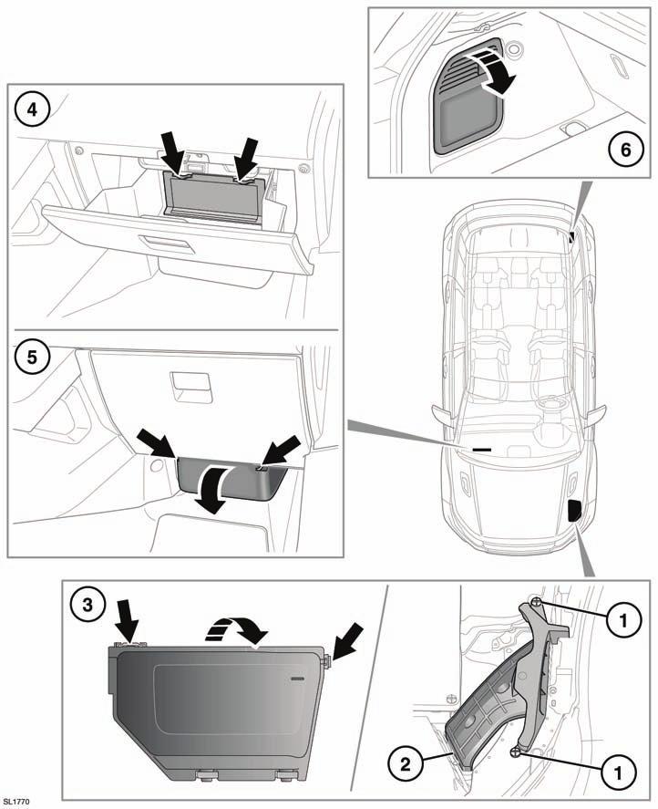
2 When a fuse box lid is removed, take care to protect the box from moisture, and refit the lid at the earliest opportunity. Engine compartment - fuse box access: 1. Remove the two plastic fixings. 2. Pull the tube up to release from the air box. 3. Delatch the tabs. The fuse box can now be opened. The engine compartment fuse numbers and positions are shown on the inside of the fuse box cover. Passenger compartment - fuse box access. There are two covers. 4. To access the upper part, open the glovebox and remove the panel from the glovebox liner. A label on the panel shows the circuits protected and the fuse locations. 5. To access the lower part, remove the lower access panel. Luggage compartment - fuse box access: 6. Remove the panel from the left side trim of the luggage compartment. A label on the panel shows the circuits protected and the fuse locations. CHANGING A FUSE Always turn off the ignition system and the affected electrical circuit, before replacing a fuse. Fit Land Rover approved replacement fuses of the same rating and type, or fuses of matching specification. Using an incorrect fuse, may result in damage to the vehicle's electrical system and can result in a fire. If the replacement fuse blows after installation, the system should be checked by your Dealer/Authorised Repairer. Note: Land Rover recommend that relays should only be replaced by qualified persons. The fuse removal tweezers are located in the passenger compartment fusebox. Press the tweezers onto the head of a fuse and pull to remove. A break in the wire inside the fuse indicates that the fuse has blown and must be replaced. There are some spare replacement fuses in the passenger compartment fusebox. See the fuse box label for details. 207
3 ENGINE COMPARTMENT FUSE BOX 1 Diode - Engine management supply 2 5 tan Voltage module supply Cooling fans Diesel - Glow plugs Electric power assisted steering 6 15 blue Oxygen sensors 7 5 tan Engine management, A/C clutch 8 20 yellow Diesel and Petrol - Engine management ECU 9 10 red Diesel - Engine sensors yellow Automatic transmission red Diesel and Petrol - Engine sensors blue Diesel - EGR bypass Petrol - Ignition coils red A/C clutch blue Diesel - Engine sensors green Starter motor PTC heater Passenger compartment fuse box Passenger compartment fuse box Luggage compartment fuse box Luggage compartment fuse box Voltage module supply pink Front wipers green Passenger compartment fuse box Not used pink Anti lock braking system green Anti lock braking system green Passenger compartment fuse box green Heater blower pink Electric trailer brake -Australia blue Headlamp washer 208
4 31 15 blue Horns yellow Auxiliary heater 33 5 tan Relay coils - Horn, Heated front screen, Fuel pump green LH Heated front screen green RH Heated front screen 36 5 tan Auxiliary water pump yellow Fuel pump Not used Not used 40 5 tan AFS (RH) headlamp 41 5 tan AFS (LH) headlamp 42 5 tan Headlamp control, Dynamic headlamp levelling control unit 43 5 tan High beam assist, rear view camera, red Heated steering wheel 45 5 tan Diesel - Auxiliary water pump, water in fuel sensor 209
5 PASSENGER COMPARTMENT FUSE BOX 1 5 tan Smart key receiver, Alarm sensor, TPM system Not used 3 10 red Front fog lamps Not used 5 5 tan Antilock braking system 6 5 tan Engine/luggage compartment fusebox Not used 8 25 clear Passenger door module 9 5 tan Electric parking brake 10 5 tan Heated washer jets red Reverse light trailer 12 5 tan Reverse lights Not used 14 5 tan Brake pedal switch green Heated rear screen 16 5 tan Electric power assisted steering 17 5 tan Keyless entry control module Not used 19 5 tan Engine management control module 20 5 tan Accelerator pedal 21 5 tan PTC heater control unit, Centre console switch, Outboard fascia switch 22 5 tan Automatic transmission Not used 24 5 tan RH rear fog lamp 25 5 tan LH rear fog lamp Not used red Trailer position lamps Not used Not used Not used 210
6 31 5 tan Rain sensor, Auxiliary lamp switch, Voltage module, Humidity sensor, Passenger airbag disabling lamp clear Drivers door module Not used red Fuel flap locking/fuel flap unlocking Not used 36 5 tan Battery backed sounder yellow Keyless entry control module blue Front screen washer clear LH rear door module 40 5 tan Driver door window switch, Clock, Pass front seat logic lumbar Not used green Driver front seat blue Rear screen washer clear RH rear door module green Passenger front seat Not used yellow Sunblind control unit blue Trailer connector Vbatt Not used Not used 51 5 tan Steering wheel switches yellow Front cigar lighter yellow Accessory socket - cubby box Not used yellow Accessory socket - rear console red SRS system red Interior lamps Not used Not used Not used 211
7 61 5 tan Start control unit red Climate control system yellow Accessory socket - load space Not used Not used 66 5 tan Diagnostics blue Trailer Not used blue Automatic transmission 212
8 LUGGAGE COMPARTMENT FUSE BOX FA1 10 red Touch screen FA2 15 blue Radio module FA3 10 red Digital radio/tv module FA4 15 blue Rear seat entertainment FA5 5 tan Seat switches FA6 30 green Electric park brake FA7 15 blue Rear wiper FA8 30 green Electric parking brake FA9 - - Not used FA10 5 tan Amplifier FA11 40 green Amplifier FA Not used FB1 5 tan Adaptive dynamics FB2 15 blue E differential module FB3 15 blue Driver seat heater FB4 15 blue Passenger seat heater FB5 30 green Adaptive dynamics FB6 25 clear Power tailgate FB7 5 tan Fuel burning heater RF receiver FB8 10 red Instrument cluster FB9 5 tan Proximity camera FB10 5 tan Blindspot monitoring FB Not used FB Not used 213
Fuses FUSE BOX LOCATIONS. Engine compartment fuse box
 FUSE BOX LOCATIONS Engine compartment fuse box 1 2 LAN2333 Remove the plastic cover by pressing the tabs. The fuse values and locations and the circuits protected are shown on the plastic cover. LAN2332
Fuses FUSE BOX LOCATIONS. Engine compartment fuse box
 Fuses FUSE BOX LOCATIONS Engine compartment fuse box 1 2 E90971 Remove the plastic cover by pressing the tabs. The fuse values and locations and the circuits protected are shown on the plastic cover. 3
JLK-019. Jaguar Dealer. After renewing a fuse have the circuit checked by
 4-12 Roadside emergency service s and Boxes failure is signalled by an inoperative circuit. Do not fit a new fuse if damage to the wiring is found; contact a Jaguar Dealer. After renewing a fuse have the
FUSE DETAILS. Fuse Details
 2003 Jaguar S-Type (X200) V8-4.2L Vehicle > Power and Ground Distribution > Fuse > Application and ID > Components FUSE DETAILS Fuse Details https://my.alldata.com/repair/#/repair/article/40444/component/1169/itype/389/nonstandard/1247914
Fuse and Relay Information
 11-1 Fuse and Relay Information Battery Junction Box (BJB) (14A003) PCM power diode Air suspension compressor Front fog lamp cutoff Police power Traction control indicator A/C clutch Fuel pump C1300 C1008
1 of :51
 1 of 5 13.05.2012 19:51 Μεταχειρισμένα Αυτοκίνητα Βρες τις πληροφορίες που ψάχνεις στην οθόνη του υπολογιστή σου! www.xo.gr 4x4 Αυτοκίνητο Αναζήτησε Ανάμεσα σε 76 Μοντέλα, Aυτό που Σου Ταιριάζει από 12.690
C915 - A147 Powertrain control module (PCM) C916 - A7 ABS control module
 C916 - A7 ABS control module") C915 - A147 Powertrain control module (PCM) C916 - A7 ABS control module C1152 - K11 Intermittent wiper relay, front C1153 - K1 Rear window heater relay C1154 - K18 ABS main relay C1155 - K25 ABS Pump
C915 - A147 Powertrain control module (PCM) C916 - A7 ABS control module C1152 - K11 Intermittent wiper relay, front C1153 - K1 Rear window heater relay C1154 - K18 ABS main relay C1155 - K25 ABS Pump
2000 Volkswagen Jetta GL
 Fig. 8: Locating Battery Fuse Panel Fuses Courtesy of VOLKSWAGEN UNITED STATES, INC. FUSE IDENTIFICATION (BATTERY FUSE PANEL) Fuse No. Amp Circuits Protected Rating 162 Engine Codes 50 Secondary Air Injector
G ELECTRICAL WIRING ROUTING
 2 6 G ELECTRICAL WIRING ROUTING Position of Parts in Engine Compartment A1 A/C Front Magnetic Valve A3 A/C Magnetic Clutch A6 A/T Flud Temp. Sensor A7 ABS Actuator A8 ABS Actuator A10 ABS Speed Sensor
CONFIGURATION DIAGRAMS
 GROUP 80 CONFIGURATION DIAGRAMS CONTENTS OVERALL CONFIGURATION DIAGRAM...................... 80-2......... 80-3 .. 80-3 .. 80-5 ...... 80-7 INSTRUMENT PANEL............ 80-9 FLOOR
G ELECTRICAL WIRING ROUTING
 G ELECTRICAL WIRING ROUTING Position of Parts in Engine Compartment A 1 A/C Condenser Fan Motor A 2 A/C Magnetic Clutch and Lock Sensor A 3 A/C Triple Pressure SW (A/C Dual and Signal Pressure SW) A 4
Passat Fitting Locations No. 208 / 1 Edition
 Sivu 1/11 Passat Fitting Locations No. 208 / 1 Edition 02.2007 Relay and fuse assignment From May 2002 Relay locations on 13 position additional relay carrier above relay plate 1 - Radiator fan relay -
L PART NUMBER OF CONNECTORS
 L PART NUMBER OF CONNECTORS Code Part Name Part Number Code Part Name Part Number A 1 A/C Ambient Temp. Sensor 90980-11070 B15 Blower Motor Controller (Rear) 90980-11136 A 2 A/C Magnetic Clutch 90980-11271
SECTION 9A BODY WIRING SYSTEM
 SECTION 9A BODY WIRING SYSTEM Caution: Disconnect the negative battery cable before removing or installing any electrical unit or when a tool or equipment could easily come in contact with exposed electrical
1. CAUTIONS WHEN WORKING ON ELECTRICAL UNITS
 841006 013 Fuse and relay 841006 1. CAUTIONS WHEN WORKING ON ELECTRICAL UNITS Remove the negative battery cable from the battery in advance when working on electrical units. Make sure to turn "OFF" the
POWER SOURCE (Current Flow Chart)
") POWER SOURCE (Current Flow Chart) The chart below shows the route by which current flows from the battery to each electrical source (Fusible Link, Circuit Breaker, Fuse, etc.) and other parts. The next
POWER SOURCE (Current Flow Chart) The chart below shows the route by which current flows from the battery to each electrical source (Fusible Link, Circuit Breaker, Fuse, etc.) and other parts. The next
3/25 Switch, power sunroof 3/26 Control module, driver's seat 3/27 Control module, passenger's seat 3/28 Switch for heated driver's seat 3/29 Switch
 List of Components 1/1 Battery 2/1 Headlight relay with bulb failure sensor 2/2 Foglight relay 2/3 Regulator DIM-DIP 2/4 Intermittent wiper relay, windshield wipers 2/5 Relay, seat belt reminder/ignition
Position of Parts in Engine Compartment
 ELECTRICAL WIRING ROUTING [5S FE] Position of Parts in Engine Compartment A 1 A/C Ambient Temp. Sensor D 1 Distributor A 2 A/C Condenser Fan Motor A 3 A/C Idle Up VSV E 1 ECT Solenoid A 4 A/C Magnet Clutch
POWER SOURCE (Current Flow Chart)
") The chart below shows the route by which current flows from the battery to each electrical source (Fusible Link, Circuit Breaker, Fuse, etc.) and other parts. The next page and following pages show the
The chart below shows the route by which current flows from the battery to each electrical source (Fusible Link, Circuit Breaker, Fuse, etc.) and other parts. The next page and following pages show the
CONFIGURATION DIAGRAMS
 80-1 GROUP 80 CONFIGURATION DIAGRAMS CONTENTS CONFIGURATION DIAGRAMS......................... 80A SPLICE LOCATIONS................................. 80B 80A-2 GROUP 80A CONFIGURATION DIAGRAMS CONTENTS OVERALL
G ELECTRICAL WIRING ROUTING
 2 6 G ELECTRICAL WIRING ROUTING [2JZ-GTE] Position of Parts in Engine Compartment A 1 A/C Ambient Temp Sensor A 2 A/C Condensor Fan Motor A 3 A/C Triple Pressure SW (A/C Dual and Single Pressure SW) A
G ELECTRICAL WIRING ROUTING
 G ELECTRICAL WIRING ROUTING Position of Parts in Engine Compartment A 1 A/C Condenser Fan Motor A 2 A/C Magnetic Clutch and Lock Sensor A 3 A/C Triple Pressure SW (A/C Dual and Single Pressure SW) A 4
Fuse and Relay Information
 11 1 Fuse and Relay Information Central Junction Box (CJB) (14A067) PCM power Trailer tow, battery charge Starter (11450) Blower motor Rear window defrost F2.602 C270p F2.101 F2.107 F2.102 F2.108 F2.601
3/22 Switch for rear power window lifts 3/23 Switch for power door mirror, driver's side 3/24 Switch for power door mirror, passenger's side 3/25
 List of Components 1/1 Battery 2/2 Relay, front foglights USA/CDN 2/3 Regulator DIM-DIP 2/4 Intermittent relay, windshield wipers 2/5 Relay, seat belt reminder/ignition key warning 2/6 Bypass relay 151
Position of Parts in Engine Compartment
 ELECTRICAL WIRING ROUTING [5S FE] Position of Parts in Engine Compartment A 1 A/C Condenser Fan Motor E 4 Engine Coolant Temp. Sensor (EFI Water Temp. A 2 A/C Magnetic Clutch and Lock Sensor Sensor) A
G ELECTRICAL WIRING ROUTING
 G ELECTRICAL WIRING ROUTING Position of Parts in Engine Compartment A 1 A/C Ambient Temp. Sensor A 2 A/C Condenser Fan Motor A 3 A/C Magnetic Clutch and Lock Sensor A 4 A/C Triple Pressure SW (A/C Dual
4-2 Roadside emergency service Spare Wheel Stowage When the temporary-use spare wheel is being used, stow the replaced road wheel in the luggage compa
 4 Roadside emergency service Roadside emergency service 4-1 Introduction In the event of a flat tyre, drivers should follow closely the procedure for wheel changing and jacking given in this section. The
FUSES & CIRCUIT BREAKERS Ford Taurus LX
 Page 1 of 7 ARTICLE BEGINNING FUSES & CIRCUIT BREAKERS Interior Fuse Panel Identification Fuse panel is located to left of steering column under instrument panel. To expose fuse panel, pull release bar
1994 Cadillac Seville STS
 Fig. 2: High-Current Fuse Panel ID (1994-95 Seville) L/H Maxi-Fuse & Circuit Breaker Identification 1-50 Amp STRG 1-2 Retained Accessory Power (Radio/Wipers), Starter, Trunk Comp Fuses 8 & 9 2-60 Amp BODY
Position of Parts in Engine Compartment
 ELECTRICAL WIRING ROUTING [3S GTE] Position of Parts in Engine Compartment A 1 A/C Ambient Temp. Sensor D 1 Date Link Connector 1 (Check Connector) A 2 A/C Condenser Fan Motor D 2 Distributor A 4 A/C Magnetic
6-3 [D5A0] WIRING DIAGRAM. 5. Wiring Diagram. 5. Wiring Diagram A: POWER SUPPLY ROUTING SU01-04A
![6-3 [D5A0] WIRING DIAGRAM. 5. Wiring Diagram. 5. Wiring Diagram A: POWER SUPPLY ROUTING SU01-04A](/thumbs/95/126021946.jpg "6-3 [D5A0] WIRING DIAGRAM. 5. Wiring Diagram. 5. Wiring Diagram A: POWER SUPPLY ROUTING SU01-04A") 6-3 [D5A0] WIRING DIAGRAM A: POWER SUPPLY ROUTING SU01-04A 12 WIRING DIAGRAM [D5A0] 6-3 SU01-04B 13 6-3 [D5A0] WIRING DIAGRAM No. Load No. Load MB-1 MB-2 MB-3 MB-4 MB-5 MB-6 MB-7 MB-8 MB-9 MB-10 SBF-7
6-3 [D5A0] WIRING DIAGRAM A: POWER SUPPLY ROUTING SU01-04A 12 WIRING DIAGRAM [D5A0] 6-3 SU01-04B 13 6-3 [D5A0] WIRING DIAGRAM No. Load No. Load MB-1 MB-2 MB-3 MB-4 MB-5 MB-6 MB-7 MB-8 MB-9 MB-10 SBF-7
5/16/2017 ALLDATA Repair - Vehicle Information Volvo V L5-2.4L VIN 61 B5244S
 1/1 Battery 2/16 Relay, Intermittent Rear Window Wiping On/Off 2/17 Horn Relay 2/22 AC Relay 2/23 Fuel Pump Relay 2/29 Relay, Extended D1 Feed 2/30 X Feed Overload Relay 2/31 15-Feed Overload Relay 2/32
Position of Parts in Engine Compartment
 [1UZ FE] Position of Parts in Engine Compartment A 1 A/C Ambient Temp. Sensor E 4 Engine Coolant Temp. Sensor (Water Temp. Sensor A 2 A/C Dual Pressure SW and A/C High Pressure SW (for Cooling Fan)) A
Layout Diagrams. Section CONTENTS. General Layout Diagram Floor / Roof Engine Compartment Door
 1-1 Section 1 Layout Diagrams CONTENTS General Layout Diagram...1-3 Engine Compartment...1-4 Engine / Transmission...1-6 Floor / Roof...1-16 Door...1-18 Boot Compartment...1-20 Instrument Panel...1-10
G ELECTRICAL WIRING ROUTING [5VZ FE] TOYOTA TACOMA (EWD517U) Position of Parts in Engine Compartment
![G ELECTRICAL WIRING ROUTING [5VZ FE] TOYOTA TACOMA (EWD517U) Position of Parts in Engine Compartment](/thumbs/82/86578697.jpg "G ELECTRICAL WIRING ROUTING [5VZ FE] TOYOTA TACOMA (EWD517U) Position of Parts in Engine Compartment") G ELECTRICAL WIRING ROUTING [5VZ FE] Position of Parts in Engine Compartment A 5 A/C Magnetic Clutch A 7 A/T Oil Temp. Sensor A22 ABS Actuator with ECU A23 Air Fuel Ratio Sensor (Bank 1 Sensor 1) A24 ADD
G ELECTRICAL WIRING ROUTING [5VZ FE] Position of Parts in Engine Compartment A 5 A/C Magnetic Clutch A 7 A/T Oil Temp. Sensor A22 ABS Actuator with ECU A23 Air Fuel Ratio Sensor (Bank 1 Sensor 1) A24 ADD
G ELECTRICAL WIRING ROUTING [1MZ-FE] Position of Parts in Engine Compartment
![G ELECTRICAL WIRING ROUTING [1MZ-FE] Position of Parts in Engine Compartment](/thumbs/87/97394184.jpg "G ELECTRICAL WIRING ROUTING [1MZ-FE] Position of Parts in Engine Compartment") G ELECTRICAL WIRING ROUTING [1MZ-FE] Position of Parts in Engine Compartment A 1 A/C Ambient Temp. Sensor A 2 A/C Condenser Fan Motor A 3 A/C Magnetic Clutch and Lock Sensor A 4 A/C Triple Pressure SW
G ELECTRICAL WIRING ROUTING [1MZ-FE] Position of Parts in Engine Compartment A 1 A/C Ambient Temp. Sensor A 2 A/C Condenser Fan Motor A 3 A/C Magnetic Clutch and Lock Sensor A 4 A/C Triple Pressure SW
Pin assignments at plug connector A173*1B. Pin assignments at plug connector A173*2B
 FEM Connector location views Number X-pin, colour Description A173*1B 1-pin, black Component connector Front Electronic Module A173*2B 42-pin, black Component connector Front Electronic Module A173*3B
D D
 GF00.19-D-3100-24B Arrangement and assignment of terminal MODEL 901.6, 902.6, 903.6, 904.6, blocks of instrument cluster 905.6 with CODE (J58) Seat belt warning device with CODE (J59) Vehicle speed limit
Section 3 Electrical system
 S40(04-) Section 3 Electrical system Section 3 Electrical system Group 31 Battery System voltage, with ignition off: A newly charged battery may have a higher voltage. 12.5-12.7 V Battery capacity Cold
CONFIGURATION DIAGRAMS
 80A-1 GROUP 80A CONFIGURATION DIAGRAMS CONTENTS OVERALL CONFIGURATION DIAGRAM...................... 80A-2 HOW TO READ CONFIGURATION DIAGRAMS.................... 80A-3 ENGINE COMPARTMENT......... 80A-4
Lotus Service Notes Section MVc
 Lotus Service Notes MVc - CIRCUIT DIAGRAMS Exige Sport 350 models from '16my start of production For '12my - '16my exige s models refer to separate section mva for manual or mvb for automatic transmission
Fuses and Relays CONTENTS FUSE AND RELAY BOARDS ( ) K4M690-K4M694 ENGINES 13
 K4M690-K4M694 ENGINES 13") CONTENTS PASSENGER COMPARTMENT FUSE UNIT (1016) 2 CHILD SAFETY RELAY (750) 8 PASSENGER COMPARTMENT CENTRAL UNIT (645) 9 FUSE AND RELAY BOARDS (233-299-336-597-784-1047-1639) K4M690-K4M694 ENGINES 13 FUSE
CONTENTS PASSENGER COMPARTMENT FUSE UNIT (1016) 2 CHILD SAFETY RELAY (750) 8 PASSENGER COMPARTMENT CENTRAL UNIT (645) 9 FUSE AND RELAY BOARDS (233-299-336-597-784-1047-1639) K4M690-K4M694 ENGINES 13 FUSE
Underhood fuse block is located at the left side of the engine compartment to the rear of the battery. See Fig. 7.
 Page 1 of 5 UNDERHOOD FUSE BLOCK NOTE: Underhood fuse block is located at the left side of the engine compartment to the rear of the battery. See Fig. 7. Fig. 7: Locating Underhood Fuse Block Courtesy
UNIVERSAL WIRING HARNESS Installation Manual
 UNIVERSAL WIRING HARNESS Installation Manual Terminals are provided for most connections on your wiring kit. Following the gauge manufacturer s instructions, use the terminals supplied with your gauge
IDENTIFICATION IDENTIFICATION > ENGINE COMPARTMENT FUSE/RELAY CENTER Chevrolet Colorado 3.5L Eng. Vehicle Reference: FUSES & CIRCUIT BREAKERS
 1 of 6 2/1/2015 5:42 PM Vehicle Reference: FUSES & CIRCUIT BREAKERS IDENTIFICATION 2005 Chevrolet Colorado 3.5L Eng CAUTION: When battery is disconnected, vehicle computer and memory systems may lose memory
CONFIGURATION DIAGRAMS
 80A-1 GROUP 80A CONFIGURATION DIAGRAMS CONTENTS OVERALL CONFIGURATION DIAGRAM...................... 80A-2 HOW TO READ CONFIGURATION DIAGRAMS.................... 80A-3 ENGINE COMPARTMENT......... 80A-4
G ELECTRICAL WIRING ROUTING [2ZZ GE] Position of Parts in Engine Compartment
![G ELECTRICAL WIRING ROUTING [2ZZ GE] Position of Parts in Engine Compartment](/thumbs/82/84806793.jpg "G ELECTRICAL WIRING ROUTING [2ZZ GE] Position of Parts in Engine Compartment") G ELECTRICAL WIRING ROUTING [2ZZ GE] Position of Parts in Engine Compartment A 1 A/C Magnetic Clutch A 2 ABS Speed Sensor Front LH A 3 ABS Speed Sensor Front RH A 4 Airbag Sensor Front LH A 5 Airbag Sensor
G ELECTRICAL WIRING ROUTING [2ZZ GE] Position of Parts in Engine Compartment A 1 A/C Magnetic Clutch A 2 ABS Speed Sensor Front LH A 3 ABS Speed Sensor Front RH A 4 Airbag Sensor Front LH A 5 Airbag Sensor
Powertrain Management: Electrical Diagrams Fuel Injection System
 1995 Volvo 940 L4-2.3L SOHC VIN 88 B230F Copyright 2009, ALLDATA 9.70 Page 1 Powertrain Management: Electrical Diagrams Fuel Injection System Wiring Diagram 1995 Volvo 940 L4-2.3L SOHC VIN 88 B230F Copyright
FUSES & CIRCUIT BREAKERS
 FUSES & CIRCUIT BREAKERS FUSES & CIRCUIT BREAKERS 1989-95 FUSES & CIRCUIT BREAKERS Ford Motor Co. INTERIOR FUSE PANEL IDENTIFICATION (1983-88 MODELS) On all models, the fuse panel is located under the
Onboard power supply management
 Onboard power supply management The onboard power supply J519 Functions of onboard power supply control unit Until now s and relays functioned at different locations in the vehicle. In the onboard power
Wheel Changing TOOL KIT
 Wheel Changing Roadside Emergency TOOL KIT H682G On seven-seat vehicles, the wheel change tool kit is stowed behind an access cover in the rear loadspace area. Note: Take careful note of the stowage position
WIRING DIAGRAM 1. General Description
 Page 1. General Description...1 2. Wiring Diagram...10 (1) POWER SUPPLY ROUTING...10 (2) ENGINE CONTROL SYSTEM (SOHC)...14 (3) ENGINE CONTROL SYSTEM (2.0 DOHC NA)...18 (4) ENGINE CONTROL SYSTEM (2.5 )...22
LIST OF COMPONENTS (SECTION 1) B001: mixed bridge block 1 B002: mixed bridge block 2 B003: mixed bridge block 3 BB00: battery BB01: battery assembly
 B001: mixed bridge block 1 B002: mixed bridge block 2 B003: mixed bridge block 3 BB00: battery BB01: battery assembly") LIST OF COMPONENTS (SECTION 1) B001: mixed bridge block 1 B002: mixed bridge block 2 B003: mixed bridge block 3 BB00: battery BB01: battery assembly (rear) BB02: battery assembly (lower front) ВВ0З: battery
LIST OF COMPONENTS (SECTION 1) B001: mixed bridge block 1 B002: mixed bridge block 2 B003: mixed bridge block 3 BB00: battery BB01: battery assembly (rear) BB02: battery assembly (lower front) ВВ0З: battery
List of components 1:6
 List of components 1:6 1/1 Battery 2/16 Relay, rear window wiper 2/17 Relay, horn 2/22 Relay, climate control system 2/23 Relay, fuel pump 2/32 Main relay, engine management system 2/34 Relay, front fog
Lotus Service Notes Section MP.14h
 Lotus Service Notes Section MP.14h ELECTRICS SECTION MP.14h CIRCUIT DIAGRAMS 2012MY ELISE 1ZR & 2ZR POWERTRAIN FROM VIN CH_10205 ONWARDS Description Page Contents List Circuit Diagrams 2 Circuit Diagrams
Wheel Changing TOOL KIT WARNING. Tools
 Wheel Changing Emergency Information Wheel Changing TOOL KIT Tools H3497 The tool kit contains the jack, wheel chock, wheel nut spanner and locking wheel nut socket and extractor tool*. H3492 The tool
Wheel Changing TOOL KIT STORED LOCATION. Five seat vehicles. Seven seat vehicles
 Wheel Changing Roadside Emergency TOOL KIT STORED LOCATION Five seat vehicles Seven seat vehicles H683G H682G On seven-seat vehicles, the wheel change tool kit is stowed behind an access cover in the rear
 http://www.prodemand.com/print/index?content=tabs&module=true&tab=true&terms=tr... Page of 8//0 Service Manual: SYSTEM WIRING DIAGRAMS DISTRIBUTION 00 Ford Taurus.L Eng Limited Fig : Power Distribution
Buckle SW Rear RH C 1 Camshaft Position Sensor Camshaft Timing Oil Control Valve RH. Crankshaft Position Sensor
 A 1 A/C Ambient Temp. Sensor 90980 11070 A 2 A/C Magnetic Clutch and ock Sensor 90980 11016 A 3 A/C Pressure Sensor 90980 10845 A 4 A/C Solenoid 90980 10901 A 5 ABS & TRAC & VSC Actuator 90980 11451 A
1993 FD3S Touring Trim Electrical FSM Index/Supplement
 1993 FD3S Touring Trim Electrical FSM Index/Supplement Purpose: This is simply a searchable index of connectors that are found in the various 1993 FD3S wiring harnesses. Each entry shows the purpose of
COOLING FAN DEFOGGERS HORN POWER ANTENNA POWER DOOR LOCKS POWER MIRRORS POWER SEATS POWER WINDOWS RADIO 2.3L. Fig. 1: 2.3L Turbo, Cooling Fan Circuit
 COOLING FAN 2.3L Fig. 1: 2.3L Turbo, Cooling Fan Circuit DEFOGGERS Fig. 2: Defogger Circuit, W/ Electronic ATC Fig. 3: Defogger Circuit, W/O Electronic ATC HORN Fig. 4: Horn Circuit POWER ANTENNA Fig.
1 f545633b PNDB CLDS Schematic 1 page. 2 A KIT-ELEC, POWERTRAIN PDM 1 page. 3A-3B A KIT-ELEC, POWERTRAIN PDM 2 pages
 1 f545633b PNDB CLDS Schematic 1 page 2 A06-64611 KIT-ELEC, POWERTRAIN PDM 1 page 3A-3B A06-74514 KIT-ELEC, POWERTRAIN PDM 2 pages 4A-4B G06-64121 WRG-BAT, LOW VOLTAGE DISCONNRCT 2 pages 5A-5B G06-61495
(1,1) Index 14 北米Model "A1330BE-B" EDITED: 2017/ 11/ 30
 Index 14 北米Model A1330BE-B EDITED: 2017/ 11/ 30") Index 14 14-2 Index A Abbreviation... 3 ABS (Anti-lock Brake System)... 7-33 Warning light... 3-20 Access key fob... 2-3 Warning light... 3-25 Accessories... 11-37 Accessory power outlet... 6-7 Air cleaner
Index 14 14-2 Index A Abbreviation... 3 ABS (Anti-lock Brake System)... 7-33 Warning light... 3-20 Access key fob... 2-3 Warning light... 3-25 Accessories... 11-37 Accessory power outlet... 6-7 Air cleaner
CIRCUIT DIAGRAMS GROUP CONTENTS HOW TO READ CIRCUIT DIAGRAMS BACKUP LIGHT TURN SIGNAL LIGHT AND HAZARD WARNING LIGHT...
 90-1 GROUP 90 CIRCUIT DIAGRAMS CONTENTS HOW TO READ CIRCUIT DIAGRAMS................................. 90-4 JUNCTION BLOCK.............. 90-10............. 90-12 CENTRALIZED JUNCTION........ 90-18 POWER
Lotus Service Notes Section MVd
 Lotus Service Notes MVd - CIRCUIT DIAGRAMS EXIGE SPORT 380 MODELS FROM '17MY START OF PRODUCTION FOR '12MY - '16MY EXIGE S MODELS REFER TO SEPARATE SECTION MVa FOR MANUAL OR MVb FOR AUTOMATIC TRANSMISSION
Inertia Switch ! WARNING: Inertia Switch Operation. Resetting the switch
 R Inertia Switch Roadside Emergency Inertia Switch Operation Resetting the switch In the event of an accident, an inertia switch may trip, isolating fuel pump operation. Once the switch has tripped it
 http://www.prodemand.com/print/index?content=tabs&module=true&tab=true&terms=tru... Page of 8 8//07 008 Ford Expedition.L Eng VIN Service Manual: SYSTEM WIRING DIAGRAMS Print Date: 8//07 LIGHTS Fig : Backup
BATTERY - HEADLIGHTS Special notes 80
 BATTERY - HEADLIGHTS Special notes 80 BATTERY - HEADLIGHTS Special notes 80 BATTERY - HEADLIGHTS Lens units 80 BATTERY - HEADLIGHTS Lens units 80 BATTERY - HEADLIGHTS Lens units 80 BATTERY - HEADLIGHTS
Quick Overview WARNING LIGHTS
 Quick Overview WARNING LIGHTS 1. Left-hand direction indicator. 2. Low outside temperature. 3. Glow plug (diesel only). 4. Engine malfunction. 5. Low oil pressure. 6. Battery charge indicator. 7. Front
COMPONENT LOCATIONS GROUP 70 CONTENTS INSPECTION CONNECTOR AND SPARE CONNECTOR SENSOR DIODE SOLENOID VALVE...
 GROUP 70 COMPONENT LOCTIONS CONTENTS SENSOR....................... 70-2 DIODE........................ 70-8 ECU.......................... 70-9 FUSIBLE LINK ND FUSE........ 70-11 RELY........................
FUSES & CIRCUIT BREAKERS
 FUSES & CIRCUIT BREAKERS FUSES & CIRCUIT BREAKERS 1995 General Motors Corp. FUSES & CIRCUIT BREAKERS FUSE PANEL IDENTIFICATION (INSTRUMENT PANEL) Friday, November 27, 2009 5:05:35 5:05:39 PM Page 1 2005
Diagnostic Trouble Code (DTC) Chart
 Chart") SECTION 419-10: Multifunction Electronic Modules 2009 Mustang Workshop Manual DIAGNOSIS AND TESTING Procedure revision date: 07/31/2009 Diagnostic Trouble Code (DTC) Chart NOTE: Most powertrain (P-code)
SECTION 419-10: Multifunction Electronic Modules 2009 Mustang Workshop Manual DIAGNOSIS AND TESTING Procedure revision date: 07/31/2009 Diagnostic Trouble Code (DTC) Chart NOTE: Most powertrain (P-code)
IDENTIFICATION COMPONENT LOCATION MENU
 WIRING DIAGRAMS 1993 Mitsubishi Diamante 1993 WIRING DIAGRAMS Mitsubishi Wiring Diagrams Mitsubishi; Diamante IDENTIFICATION COMPONENT LOCATION MENU COMPONENT LOCATIONS TABLE Component Figure No. (Location)
Volkswagen Cabriolet DIY Guide Relay/Fuse Diagrams & Electrical System
 Volkswagen Cabriolet DIY Guide Relay/Fuse Diagrams & Electrical System Notes: 1980-1982 cars use ceramic fuses! 1980-1982 cars had a recall for the fuel pump relay. These cars should have a relay bypass
Black plate (27,1) Index 14 北米Model "A3180BE-B" EDITED: 2014/ 2/ 7
 Index 14 北米Model A3180BE-B EDITED: 2014/ 2/ 7") Index 14 14-2 Index A Abbreviation... 3 ABS (Anti-lock Brake System)... 7-20 Warning light... 3-15, 7-21 Accessories... 5-2, 11-36 Accessory power outlet... 6-10 Active head restraint... 1-6 Air cleaner
Index 14 14-2 Index A Abbreviation... 3 ABS (Anti-lock Brake System)... 7-20 Warning light... 3-15, 7-21 Accessories... 5-2, 11-36 Accessory power outlet... 6-10 Active head restraint... 1-6 Air cleaner
SOUL GDI REPAIR AND MAINTENANCE
 SOUL 2013-1.6 GDI REPAIR AND MAINTENANCE (First Numbers are page number within section - Numbers in parenthesis are overall document page) GENERAL INFORMATION (23 PAGES) 01-07 (01-07): Identification Number
Lotus Service Notes- Federal Evora CCT Diagrams Section MH.1a
 Lotus Service Notes- Federal - CCT Diagrams FEDERAL evora 400 CIRCUIT DIAGRAMS section mh.1a Description Page Fuse Box & Relay Layout 2 Colour Codes 5 EMS Connector Pin Out Chart 6 Contents List Circuit
Lotus Service Notes - Exige - all Models from '18 MY VIN KH_ CCT Diagrams Section MVg
 Lotus Service Notes - Exige - all Models from '18 MY VIN KH_10083 - CCT Diagrams Section MVg MVg - CIRCUIT DIAGRAMS EXIGE - ALL MODELS FITTED WITH A138M0195F AIR BAG CONTROL UNIT - FROM '19MY VIN KH_10083
Fuse/Relay Information
 /Relay Information Under-dash /Relay Box C901 (To turn signal/hazard relay) C902 (To blower motor relay) C903 (To rear window defogger relay) C405 C404 C904 (To integrated control unit) C602 (To dashboard
BECM (P38 NRR) - System Overview
 - System Overview") BECM (P38 NRR) - System Overview A very Large ECU found under the seat of all P38 Range Rovers (1995 to 2002). This ECU has almost certainly been custom designed by Rover specifically for this vehicle
BECM (P38 NRR) - System Overview A very Large ECU found under the seat of all P38 Range Rovers (1995 to 2002). This ECU has almost certainly been custom designed by Rover specifically for this vehicle
List of components 1:6
 List of components 1:6 1/1 Battery 1/1 Battery 2/14 Relay, glow plug unit 2/22 Relay, climate control system 2/32 Main relay, engine management system 2/33 Relay, fuel system 2/35 Starter motor relay 2/64
remove from fuse and relay box (F1), install.
, install.") 54-1255 Front fuse and relay box/fuse boxes Operation no. of operation texts and work units or standard texts and flat rates: A. Removing and installing front fuse and relay box (up to 08/95) P54-5095-57
54-1255 Front fuse and relay box/fuse boxes Operation no. of operation texts and work units or standard texts and flat rates: A. Removing and installing front fuse and relay box (up to 08/95) P54-5095-57
LandRover V30.60Diagnostics List(Note:For reference only)
") Sys. Read Clear Data Info. Stream TD4(Engine) 1.Reset adaptions EMS2000(Engine) 1.Reset adaptions EDC Diesel(Engine) mem3 (2001 2004)(Engine) 1.Configuration mems1.9(before 2001)(Engine) 1.Configuration
Sys. Read Clear Data Info. Stream TD4(Engine) 1.Reset adaptions EMS2000(Engine) 1.Reset adaptions EDC Diesel(Engine) mem3 (2001 2004)(Engine) 1.Configuration mems1.9(before 2001)(Engine) 1.Configuration
INSTRUCTIONS. 20 Circuit Wiring Kit Instructions October 2009, Speedway Motors, Inc.
 1 MAIN FUSE PANEL The main fuse panel harness s designed to be mounted under the dash a the firewall in an area close to the steering column. The enclosed representation of the main dash harness shows
Vehicle health check ABS - ANTI LOCK BRAKE MODULE. Fault Codes. Parameters Snapshot ACM - AUDIO CONTROL MODULE. Fault Codes. Parameters Snapshot
 Vehicle health check Health check done on: 11/06/2015 08:17:25 VIN: xxxxxxxxxxxxxx Plate Number: Not Registered ABS - ANTI LOCK BRAKE MODULE Brake / Configuration and programming version --------- DTC
Fuse/Relay Information
 BD 10/24/91 kd 11/12 smk 11/14/91 MC 4/8/92 bd 4/14/92 92 PRELUDE /Relay Information Under-hood /Relay Box 47 46 45 44 43 42 41 40 39 31 49 48 51 50 37 36 35 34 33 32 C941 (To ABS motor relay) 38 C942
ELECTRICAL CENTER IDENTIFICATION VIEWS > BODY CONTROL MODULE (BCM) LABEL
 LABEL") 2008 Chevrolet Cobalt 2.2L Eng LS WIRING SYSTEMS AND POWER MANAGEMENT - COMPONENT VIEWS & COMPONENT CONNECTOR END VIEWS ELECTRICAL CENTER IDENTIFICATION VIEWS > BODY CONTROL MODULE (BCM) LABEL Fig 1: View
2008 Chevrolet Cobalt 2.2L Eng LS WIRING SYSTEMS AND POWER MANAGEMENT - COMPONENT VIEWS & COMPONENT CONNECTOR END VIEWS ELECTRICAL CENTER IDENTIFICATION VIEWS > BODY CONTROL MODULE (BCM) LABEL Fig 1: View
AERO 8 PRE-DELIVERY INSPECTION CHECKLIST CHASSIS NUMBER :- CUSTOMER :- DEALER :- DATE INSPECTED :- INSPECTED BY :- ROAD TESTED BY :- MILEAGE :-
 AERO 8 PRE-DELIVERY INSPECTION CHECKLIST CHASSIS NUMBER :- CUSTOMER :- DEALER :- DATE INSPECTED :- INSPECTED BY :- ROAD TESTED BY :- MILEAGE :- ISSUE 4 A 1 TECHNICAL INSPECTION CHECK FUNCTION WITH IGNITION
Parking Aids Reverse camera INTERIOR
 Pajero GLX 5 Door SUV, 7 Seat Diesel 2018 MY (Manual) MECHANICAL Fuel System Fuel tank capacity (L): 88 Fuel consumption (ADR 81/02 litres per 100 km): 9.1 1 Type: Common Rail Direct Injection Fuel type:
 Page of 00 Ford Freestyle.0L Eng SE Service Manual: SYSTEM WIRING DIAGRAMS Print Date: EXTERIOR LIGHTS Fig : Back-up Lamps Circuit HOT AT ALL TIMES VPWR C0E / / S / FREESTYLE FIVE HUND, MONTEGO FREESTYLE
OWNER S HANDBOOK. Publication Part No. JJM
 OWNER S HANDBOOK Publication Part No. JJM 10 02 30 901 About this handbook This handbook forms part of the Owner literature supplied with your new vehicle. Left-hand drive and right-hand drive conditions
FORD ECOSPORT Quick Reference Guide
 FORD ECOSPORT Quick Reference Guide About This Quick Reference Guide We have created this guide to help you get to know certain features of your vehicle quickly. It only contains basic instructions to
LandRover V30.50 Diagnostics List(Note:For reference only)
") Info. Stream Actuation Special Others TD4(Engine) 1.Reset adaptions EMS2000(Engine) 1.Reset adaptions EDC Diesel(Engine) mem3 (2001 2004)(Engine) 1.Configuration mems1.9(before 2001)(Engine) 1.Configuration
Info. Stream Actuation Special Others TD4(Engine) 1.Reset adaptions EMS2000(Engine) 1.Reset adaptions EDC Diesel(Engine) mem3 (2001 2004)(Engine) 1.Configuration mems1.9(before 2001)(Engine) 1.Configuration
FORD ECOSPORT Quick Reference Guide
 FORD ECOSPORT Quick Reference Guide About This Quick Reference Guide We have created this guide to help you get to know certain features of your vehicle quickly. It only contains basic instructions to
Supercharged MK1 MR2 Part Diagrams
 Supercharged MK1 MR2 Part Diagrams Created by: Charles K. (ckowalc) 1 Table of Contents PART DIAGRAM PAGE ACCELERATOR LINK 9 AIR CLEANER 10 AIR CLEANER 4AGZE 11 ALTERNATOR 4AGZE 12 ANTENNA 13 ARMREST &
Audi A4 Fitting Locations No. 803 / 1
 Page 1 of 8 Audi A4 Fitting Locations No. 803 / 1 Relays Overview of relays Overview also valid for Avant models (5-door)! 1 - Relay andfuse holder F -SF- Components: -J9-, -J84-, -J807- Location for models
ARTICLE BEGINNING FUSES & CIRCUIT BREAKERS * PLEASE READ FIRST * ALL BUT JETTA ( ) Fuses & Circuit Breakers Volkswagen ELECTRICAL
 Fuses & Circuit Breakers Volkswagen ELECTRICAL") Article Text ARTICLE BEGINNING Fuses & Circuit Breakers 1987-96 Volkswagen ELECTRICAL FUSES & CIRCUIT BREAKERS * PLEASE READ FIRST * The fuse panel is located under the left side of the dash board by the
Article Text ARTICLE BEGINNING Fuses & Circuit Breakers 1987-96 Volkswagen ELECTRICAL FUSES & CIRCUIT BREAKERS * PLEASE READ FIRST * The fuse panel is located under the left side of the dash board by the
Lighting GENERAL INFORMATION. Daytime running lamps. Halogen headlamps. Stop lamps. Bi-Xenon headlamps. Reversing lamps
 Lighting GENERAL INFORMATION There are three types of headlamp systems: Halogen high/low beam main lamp with a fill-in high beam halogen lamp alongside. Bi-xenon high/low beam main lamps with fill-in high
ARTICLE BEGINNING COMPONENT LOCATION MENU Wiring Diagrams Audi
 Article Text ARTICLE BEGINNING 1990 Wiring Diagrams Audi 200 COMPONENT LOCATION MENU COMPONENT LOCATIONS TABLE ÄÄÄÄÄÄÄÄÄÄÄÄÄÄÄÄÄÄÄÄÄÄÄÄÄÄÄÄÄÄÄÄÄÄÄÄÄÄÄÄÄÄÄÄÄÄÄÄÄÄÄÄÄÄÄÄÄÄÄÄ Component (Figure No.) Location
List of components 1:9
 List of components 1:9 1/1 Battery 1/1 Battery 2/22 Relay, climate control system 2/32 Main relay, engine management system 2/35 Relay, starter motor 2/64 Auxiliary light relay 2/64 Auxiliary light relay