1 Intended Use. 2 Precautions for handling and operation. English
|
|
|
- Nathan Carpenter
- 5 years ago
- Views:
Transcription

1
2 Thank you for purchasing the NSK icare. Please read this Operation Manual carefully before use to become familiar with operation instructions and care & maintenance. Keep this Operation Manual for future reference. English - Contents - 1. Intended Use Precautions for handling and operation Package Contents Part names Checking and how to connect each part Oil priming Check before use Operation Procedures Maintenance of icare Periodical Maintenance Checks Error LED Troubleshooting Specification Symbols Warranty Option Parts List Spare Parts List Disposal of the product EMC Information (Electromagnetic Compatibility Information) English 1 Intended Use Maintenance (lubrication and internal cleaning) of handpieces. 2 Precautions for handling and operation Please read these precautions carefully and use only as intended or instructed. Safety instructions are intended to avoid potential hazards that could result in personal injury or damage to the device. Safety instructions are classified as follows in accordance with the seriousness of the risk. Class DANGER WARNING NOTICE Degree of Risk Hazard that could result in personal death or serious injury if the safety instructions are not correctly followed. Hazard that could result in serious injury or damage to the device if the safety instructions are not correctly followed. Hazard that could result in light or moderate injury or damage to the device if the safety instructions are not correctly followed. General product specification information highlighted to avoid product malfunction and performance reduction. DANGER Do not install or use this product or fill it with Maintenance Oil in a room where explosion or fire is a risk. Do not install or use the product in direct sunlight or where the temperature exceeds 40 C. Provide adequate ventilation periodically. If odor is a concern, ventilate immediately. WARNING Do not handle the AC power cord with wet hands. Wet hand contact with electricity may result in an electric shock. If the product overheats or smells of burning, immediately turn off the power and disconnect the main power plug. Contact your Authorized NSK Dealer. TO PREVENT ELECTRIC SHOCK, use a main electrical outlet that is earthed. Be careful not to get water or liquid disinfectant or maintenance oil on the Unit. This could cause short circuits and lead to fire and/or electric shock. Excessively turning the Main Power Switch ON and OFF may blow a fuse. 1 (CS5) icare-en_ indd /05/22 9:02:53
3 When installing the product, provide space of approximately 10cm around the product for easy access to the inlet and the Power Cord. For safety, install the Unit in a place where the AC power cord can be easily removed. Read this Operation Manual before use to fully understand the product functions and file for future reference. Do not lubricate air scalers and Phatelus air motors by using icare. icare lubricating method is improper to those structure. Maintain individual handpieces according to the procedure described in the operation manual of each handpiece. If blood infiltrates inside a handpiece, icare may not totally clean the internal handpiece components, and internal blood coagulation may cause product failure. In this case, NSK recommends to immediately lubricate those handpieces with PANA SPRAY Plus / PANA SPRAY. Autoclave handpieces AFTER lubricating with this product. Place a collector such as a tray under the Unit. After use, turn off the Power Switch and shut off the air supply (Air Compressor). Drain water from the Air Compressor and Air Filter at least once a week as required. Moisture from the tank could mix with the Maintenance Oil and defeat the purpose of this device. Remove the Air Tube and the AC power cord from the Unit if the Unit is not to be used for a long time. Do not store the Maintenance Oil in contact with halogen, strong acid, alkali, and oxidizing substance or in the same place as these substances. Use only consumable parts such as maintenance oil, and accessories such as an AC power cord specified by NSK. Other than what we specify may cause product failure due to insufficient lubrication. This device is for indoor use only. Keep the Unit on a level surface. Do not attempt to disassemble the product or tamper with the mechanism except as recommended by NSK in this Operation Manual. Do not allow any impact on to the product. Do not drop the product. Should the product function abnormally, cease operation immediately and contact your Authorized NSK Dealer. Perform regular function and maintenance checks. If the product is not used for a long period check it is functioning correctly before use. Installation and use of this product requires special precautions regarding EMC according to the EMC information. Portable and mobile RF communications equipment can affect Medical Electrical equipment. Do not use RF equipment near the product. The use of ACCESSORIES such as cables, other than those specified by the manufacturer, with the exception of cables sold by the manufacturer of this product as replacement parts for internal components, may result in increased EMISSIONS or decreased IMMUNITY of this product. This product should not be used adjacent to, or stacked with, other equipment. If adjacent or stacked use is necessary, this product should be observed to verify normal operation in the configuration in which it will be used. The system may present a possibility of malfunction when used in the presence of an electromagnetic interference wave. Do not install the system in the vicinity of any device which emits magnetic waves. Turn off the Main Power Switch of the system as an ultrasonic oscillation device or an electrode knife is located close to the vicinity of use. U.S. Federal law restricts this device to sale by or on the order of a licensed physician. NOTICE No special training is required for this device. 2 (CS5) icare-en_ indd /05/22 9:02:53


 10")
")
4 3 Package Contents English No. Part Name Quantity 1 icare Unit 1 2 AC Power cord 1 3 Maintenance Oil for icare 1 4 Oil Filling Nozzle 1 5 Mist Filter Set 1set (Pack of 12) 6 Air Tube 1 7 Oil Absorber Sheet 1set (Pack of 10) 8 Chuck Cleaning Nozzle 1 9 O-ring Set 1set (Pack of 3) 10 Test Bur 1 3 (CS5) icare-en_ indd /05/22 9:02:55
 (C) Error LED (Oil) (3) Air Select Button (F) Air LED (S/M/L) (4) Start Button (1) Joint Select Button (G) Chuck Cleaning LED (2) Chuck Cleaning Button")
 Chuck Cleaning Button Use this Button when selecting Chuck Cleaning Mode. (3) Air Select Button Use this Button when selecting Air Mode.")
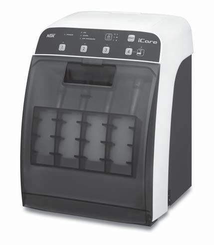
5 4 Part names icare Unit Cover Control Panel Joint Fuse Box Air Filter Power Switch Door Inlet Control Panel (A) Power LED (B) Joint LED (E) Error LED (Air Pressure) (D) Error LED (Door) (C) Error LED (Oil) (3) Air Select Button (F) Air LED (S/M/L) (4) Start Button (1) Joint Select Button (G) Chuck Cleaning LED (2) Chuck Cleaning Button 4-1 Buttons on Control Panel (1) Joint Select Button Use this Button when selecting a joint to use. (2) Chuck Cleaning Button Use this Button when selecting Chuck Cleaning Mode. (3) Air Select Button Use this Button when selecting Air Mode. (4) Start Button Use this Button when starting lubrication. 4 (CS5) icare-en_ indd /05/22 9:02:56
6 4-2 Display part on Control Panel (A) Power LED This LED lights up when power is ON (l side). (B) Joint LED This LED lights up when the joint is selected. This LED blinks during lubrication. (C) Error LED (Oil) See "11. Error LED". English (D) Error LED (Door) See "11. Error LED". (E) Error LED (Air Pressure) See "11. Error LED". (F) Air LED (S/M/L) The selected Air mode lights up. (G) Chuck Cleaning LED This LED lights up when the Chuck Cleaning is selected. This LED blinks during cleaning. 5 Checking and how to connect each part 5-1 Connecting Air Tube 1) Securely insert the Air Tube into the Air Filter Connector at the back of the Unit (Fig. 1). 2) Connect the Y-type One-Touch Connector to the air source (Air Compressor) as shown in Fig. 2. 3) Push and pull the Air Tube to be sure that it is firmly connected. Example of connection To other device Air Tube Air Filter Connector Air Filter Cut the air tube connecting the Air Compressor and the other device and connect to the Y-type One-Touch Connector. Y-type One-Touch Connector Air Filter of icare Fig. 1 Air Compressor Fig. 2 The optimum air pressure for this product is between MPa (5-6kgf/cm 2 ). The product does not operate if the air pressure is set less than 0.5MPa (5kgf/cm 2 ). Do not twist or bend the Air Tube. If you have difficulty connecting the Air Tube, contact your Authorized NSK Dealer. Drain water from the Air Compressor and Air Filter at least once a week as required. Moisture from the tank could mix with the Maintenance Oil. 5 (CS5) icare-en_ indd /05/22 9:02:56
.")
 Remove the Oil Fill Cap by turning it counter clockwise (Fig. 5).")
 Fill with Maintenance Oil slowly (Fig. 7).")


7 5-2 Filling with Maintenance Oil Before filling with Maintenance Oil, be sure that the Drain Screw on the underside of the Unit is tightened securely. Oil may leak if the screw is loose (Fig. 3). Drain Screw Fig. 3 1) Open the Cover (Fig. 4). 2) Remove the Oil Fill Cap by turning it counter clockwise (Fig. 5). 3) Remove the cap for Maintenance Oil and install the Oil Filling Nozzle (Fig. 6). 4) Fill with Maintenance Oil slowly (Fig. 7). 5) When filling is complete, securely attach the Oil Fill Cap by turning it clockwise. Cover Oil Fill Cap Fig. 4 Fig. 5 Oil Filling Nozzle Oil Filling Hole Maintenance Oil Oil Filter Fig. 6 Fig. 7 DANGER Do not fill Maintenance Oil in a room where there is a risk of explosion or fire. Do not overfill Maintenance Oil in order to avoid accidental oil leaks. Pour slowly. Use only the NSK Maintenance Oil for icare. Use of oil other than NSK Maintenance Oil for icare may cause a failure and result in insufficient product lubrication. 6 (CS5) icare-en_ indd /05/22 9:02:57
. Oil Absorber Sheet Fig.")
8 5-3 Mist Filter Attach Mist Filters to the inside of the Door (Fig. 8). Mist Filter English 5-4 Oil Absorber Sheet Place an Oil Absorber Sheet at the bottom of the lubricating chamber of the Unit. The Oil Absorber Sheet is designed to absorb residual Maintenance oil after lubrication (Fig. 9). Oil Absorber Sheet Fig Connecting AC Power Cord 1) Turn OFF (O side) the Power Switch before connecting the AC power cord. 2) Insert the AC power cord plug so that it fits the Connector Socket at the rear of the Unit (Fig. 10). 3) Plug the AC power cord into a wall outlet. Fig. 9 Fig. 10 Hold the plug when pulling out the AC power cord. If holding the cord part, the cord may be damaged. Be sure that the device has completely stopped before pulling out the AC power cord. 5-6 Setting of sound volume "High" and "Low" sound volume can be switched by repeating the following procedure. Close the Door then turn ON the Power Switch (I side) while pressing the Air Select Button. 6 Oil priming Be sure to prime icare with the Maintenance Oil when using the product for the first time or after draining the oil from the oil tank. Lack of oil priming may reduce the performance of the product. 1) Close the door then turn ON the Power Switch (l side) while pressing the Chuck Cleaning Button. Then a beep sounds. 2) Be sure that the Error LED (Oil) lights up. Then open the door. 3) Keep pressing any one of the Joint Select Button "1 to 4", while being sure that the Oil exits from the joint. 4) Close the Door. 5) Turn OFF the Power Switch (O side), and turn it ON (l side) again. 6) Press each Joint Select Button to light the Joint LED of all (1 to 4). 7) Press the Start Button to start Oil priming. 8) When Oil priming is completed, a beep sounds and the Joint LED turns off. 7 (CS5) icare-en_ indd /05/22 9:02:58

9 7 Check before use Before use, check the product by referring to the check points below. If you find something abnormal such as looseness, when checking or using, stop use and contact your Authorized NSK Dealer. Check that the turbine joint part is securely fastened and the Nut screw is free of wear, seizure or adherence of dirt. Check that the E-type joint part is secure and free of flaws or adherence of dirt. 8 Operation Procedures Do not lubricate air scalers and Phatelus air motors by using icare. icare lubricating method is improper to those structure. Maintain individual handpieces according to the procedure described in the operation manual of each handpiece. If blood infiltrates inside a handpiece, icare may not totally clean the internal handpiece components, and internal blood coagulation may cause product failure. In this case, NSK recommends to immediately lubricate those handpieces with PANA SPRAY Plus / PANA SPRAY. Maintain individual handpiece according to the procedure described in the operation manual of handpiece. 8-1 Attaching Handpiece Air Turbine When connecting a Midwest 4 Hole air turbine (According to ISO 9168) 1) Remove the bur from the handpiece. 2) Open the icare Door, insert the air turbine to the shape of the air turbine joint, and tighten the nut securely (Fig. 11). To 4) When connecting another type of air turbine 1) Remove the bur from the handpiece. 2) Open the icare Door, insert the adaptor (option) to the shape of the air turbine joint, and tighten the nut securely (Fig. 12). 3) Insert the air turbine into the adaptor (Fig. 13). * Refer to "16. Option Parts List" for the correct adaptor. To 4) 4) Push and pull the handpiece to be sure that it is securely attached. 5) Point the bur insertion hole toward the door and close the door securely (Fig. 14). Air Turbine Joint Tighten Nut Tighten Adaptor Nut *C3 Type Fig. 11 *C2 Type Fig (CS5) icare-en_ indd /05/22 9:02:58
 Straight Handpiece 1) Insert the supplied Test Bur into the handpiece and lock the chuck by turning the Bur Lock Ring (Fig. 15).")
 Close the door securely. Bur Lock Ring Point toward the door Test bur Fig. 14 Contra Angle Handpiece 1) Remove the bur from the handpiece.")
10 Bur insertion Hole Adaptor English *C2 Type Fig. 13 E Type handpiece (According to ISO 3964 type) Straight Handpiece 1) Insert the supplied Test Bur into the handpiece and lock the chuck by turning the Bur Lock Ring (Fig. 15). 2) Open the icare door and attach the handpiece to the E-Type handpiece joint until it locks (Fig. 16). 3) Push and pull the handpiece to be sure that it is securely attached. 4) Close the door securely. Bur Lock Ring Point toward the door Test bur Fig. 14 Contra Angle Handpiece 1) Remove the bur from the handpiece. 2) Open the icare door and attach the handpiece to the E-Type handpiece joint until it locks (Fig. 16). 3) Push and pull the handpiece to be sure that it is securely attached. 4) Point the bur insertion hole toward the door and close the door securely (Fig. 14). E-Type handpiece Joint Fig. 15 *C2 Type Fig. 16 Be sure to remove the bur from Air Turbine and Contra Angle Handpieces before attaching the handpiece to the adaptor or Joint. For Straight handpieces be sure to insert the supplied Test Bur and lock the chuck before connecting to the E-Type handpiece joint (Fig. 15). For Contra Angle and Air Turbine Handpieces point the Bur Insertion Hole towards the door and close the door (Fig. 14). Mist Filters absorb the oil coming out of the handpiece. NOTICE NSK offers Handpiece Head Filters, which help absorption of oil from the handpiece during lubrication. * For replacement Handpiece Head Filters, refer to "16. Option Parts List". 9 (CS5) icare-en_ indd /05/22 9:02:58
11 8-2 Lubrication and internal cleaning NOTICE icare has preset lubrication modes optimal for various handpiece types. Lubricate and clean handpieces by following the instruction below. 1) Turn on (I side) the Power Switch. 2) Press the Joint Select Button to select the joint to which handpiece is attached. The relevant LED light will illuminate. 3) Press the Air Select Button to select an air purge mode among S, M and L. Mode S mode (Short) M mode (Medium) L mode (Long) Joint Lubrication and Cleaning Time per Handpiece Handpiece Air Turbine Joint 28 sec. Air Turbine (M4/B2 type only) E-type Handpiece Joint 50 sec. Contra Angle Handpieces, Straight Handpieces (The oil drainage time is shorter than that in M mode) Air Turbine Joint 30 sec. Air Turbine (Other than M4/B2 type) E-type Handpiece Joint 64 sec. Contra Angle Handpieces, Straight Handpieces Air Turbine Joint 33 sec. Handpieces from which oil cannot be drained sufficiently in M E-type Handpiece Joint 84 sec. mode (The oil drainage time is longer than that in M mode) 4) When the Start Button is pressed lubrication starts. The Joint LED blinks during lubrication. 5) When lubrication is completed, a beep sounds and the Joint LED turns off. When Joint LED is off, lubrication for the joint will not start. 8-3 Removing Handpieces If debris is contained in the oil expelling from a handpiece even after lubrication, lubricate the handpiece again. Removing Air Turbine For Midwest 4 Hole Air Turbine (According to ISO 9168) 1) Open the door after the Joint LED has turned OFF and lubrication has completely finished. 2) Loosen the nut and pull out the handpiece straight from the Air Turbine Joint (Fig. 17). For other types of air turbine handpieces 1) Open the door after the Joint LED has turned OFF and lubrication has completely finished. 2) Pull out the Air Turbine straight from the adaptor, or pull out the Air Turbine while pushing up the connector ring of the adaptor (Fig. 18). Nut Loosen Adaptor *C3 Type Fig. 17 *C2 Type Fig (CS5) icare-en_ indd /05/22 9:02:59
 Pull out the handpiece straight while pressing the Release Button on the E-type Handpiece Joint (Fig. 19). With a cloth, wipe off any Oil collected at the bottom of the chamber and the door.")

12 Removing E-type handpieces (According to ISO 3964 type) 1) Open the door after the Joint LED has turned OFF and lubrication has completely finished. 2) Pull out the handpiece straight while pressing the Release Button on the E-type Handpiece Joint (Fig. 19). With a cloth, wipe off any Oil collected at the bottom of the chamber and the door. The collected oil could leak from the bottom of the door. Dispose of the cloth as medical waste according to the laws and regulations in your country. Release Button English *C2 Type 8-4 Chuck Cleaning This product can clean the Chuck of Air Turbine and Contra Angle handpieces. 1) Insert the chuck cleaning nozzle into the Joint "4" until it locks (Fig. 20). 2) Press the Chuck Cleaning Button to illuminate the Chuck Cleaning LED. 3) Holding the handpiece securely by hand, insert the chuck cleaning nozzle into the bur insertion hole of the handpiece (Fig. 21). 4) Press the Start Button and chuck cleaning will start. The Chuck Cleaning LED will blink during cleaning. 5) When cleaning is completed, a beep sounds and the Chuck Cleaning LED will turn off. 6) Lubricate the handpiece following the instruction in "8-1 Attaching Handpiece" and "8-2 Lubrication and internal cleaning". Fig. 19 Chuck Cleaning Nozzle *C2 Type Fig. 20 Fig. 21 Do not clean the chuck of NSK Straight Handpieces as this may cause handpiece malfunction. NOTICE Only Joint "4" is available for chuck cleaning. Clean the chuck at least once a week. 9 Maintenance of icare 9-1 Cleaning the icare 1) Turn OFF (O side) the Power Switch. 2) Remove the AC power cord from Unit. 3) Wipe the surface using a cloth moistened with water, warm water or soapy water (neutral detergent), then again wipe using another cloth moistened with disinfectant alcohol. Never use solvent such as benzine or thinner for cleaning. Do not leave an alcohol-immersed cloth in contact with the Unit for a long period. Bleaching, deformation or failure of the Unit may occur. NOTICE The door can easily be detached when necessary and be cleaned with tap water (See "9-2 Detaching and reattaching the door"). 11 (CS5) icare-en_ indd /05/22 9:02:59
 Fit the installation hole on the door into the pin on the front left side (Fig. 23).")
. Detachment lever Fig. 22 Pin Detachment lever Pin Installation hole Installation hole Fig. 23 Fig. 24 Attach or detach the door on a level surface.")

13 9-2 Detaching and reattaching the door Detaching the door Slide the detachment lever (lower right corner) inward then pull the door out to remove (Fig. 22) Reattaching the door 1) Fit the installation hole on the door into the pin on the front left side (Fig. 23). 2) Align the other installation hole on the door right side with the pin while pulling the detachment lever. Release the detachment lever. A 'click' sound will indicate that the door is secure (Fig. 24). Detachment lever Fig. 22 Pin Detachment lever Pin Installation hole Installation hole Fig. 23 Fig. 24 Attach or detach the door on a level surface. During attachment or detachment, be careful not to drop the door or the Unit. Do not soak the door in alcohol and do not leave an alcohol-immersed cloth in contact with the door for a long period. Bleaching or door deformation may occur. 9-3 Replacing Mist Filter Open the door and remove the used Mist Filters. Replace with new Mist Filters as shown in Fig. 25. Mist Filter Replace immediately with new Mist Filters when signs of debris appear. Dispose of used Mist Filters as medical waste according to the laws and regulations in your country. 9-4 Replacing the Oil Absorber Sheet Open the door and remove used Oil Absorber Sheet. Place new Oil Absorber Sheet at the bottom of the lubricating chamber of the Unit as shown in Fig. 26. Replace immediately with a new Oil Absorber Sheet when signs of debris appear. Dispose of used Oil Absorber Sheets as medical waste according to the laws and regulations in your country. Oil Absorber Sheet Fig. 25 Fig (CS5) icare-en_ indd /05/22 9:03:00
 In addition to the Air Filter, drain the air supply attached to this device (Air Compressor) at least once a week.")

 Remove the AC power cord plug from wall outlet. 3) Remove the AC power cord from the Unit. 4) Prepare an oil receiving container. 5) Remove the Oil Fill Cap.")

14 9-5 Draining the Air Filter 1) When water accumulates in the Air Filter case, press the Drain Button at the bottom of the case to drain the Air Filter (Fig. 27). 2) In addition to the Air Filter, drain the air supply attached to this device (Air Compressor) at least once a week. The air supply (Air Compressor) and Air Filter need to be clean and free from moisture. Drain the Air Compressor and Air Filter at least once a week as required. Moisture from the tank could mix with the Maintenance Oil. 9-6 Oil removal from the oil tank Before relocating or requesting product service, remove oil in the oil tank following the instruction below. 1) Turn OFF (O side) the Power Switch. 2) Remove the AC power cord plug from wall outlet. 3) Remove the AC power cord from the Unit. 4) Prepare an oil receiving container. 5) Remove the Oil Fill Cap. 6) Put the oil receiving container below the drain screw and remove the drain screw. 7) When oil draining is completed, securely fasten the drain screw. 9-7 Replacing the O-ring The O-Ring attached to the E-type handpiece joint may deteriorate or break due to wear. If any abnormality is found, replace the O-Ring with a new one following the instruction below. 1) Remove the O-ring using a thin needle (Fig. 29). 2) Insert a new O-ring into the empty groove. * For replacement O-ring, refer to the Spare Parts List. Drain Button Drain Screw Fig. 27 Fig. 28 English A deteriorated O-ring would cause excess flow of oil from the joint. If such abnormality is found, replace the O-ring with a new one. Use only the O-ring which NSK specifies. O-ring Fig Changing Fuses 1) Turn OFF (O side) the Power Switch. 2) Remove the AC power cord from the Unit. 3) Pull out and remove the Fuse while squeezing the ratchets of the Fuse Box inward at the same time (Fig. 30). 4) Replace the Fuse with a new one. 5) Place the Fuse holder in the original position. * For replacement Fuse, refer to the Spare Parts List. Fuse Box Fuse Fig. 30 Use only the fuse which NSK specifies. If you cannot identify the cause for the blowout of the fuse, be sure to contact your Authorized NSK Dealer for an inspection. NOTICE When it is difficult to pull out the fuse holder, pull it out while pushing the ratchet with a hard-tipped object. 13 (CS5) icare-en_ indd /05/22 9:03:00
 Pull out the air tube while pushing the connector ring on the air filter (Fig. 31). 3) Remove the two screws using a cross slot screwdriver to remove the air filter (Fig. 32).")
. 7) Remove the screw at the bottom of the retainer using a cross slot screwdriver (Fig. 36). 8) Remove the retainer and the air filter element.")
15 9-9 Replacing the air filter element Replace the air filter element every one or two years. 1) Drain the Air Filter (See "9-5 Draining Air Filter"). 2) Pull out the air tube while pushing the connector ring on the air filter (Fig. 31). 3) Remove the two screws using a cross slot screwdriver to remove the air filter (Fig. 32). 4) Move the red lock button down to " OPEN" (Fig. 33). 5) Turn the case supporter clockwise and pull it down. The case supporter and case guard can now be removed (Fig. 34). 6) Remove the case (Fig. 35). 7) Remove the screw at the bottom of the retainer using a cross slot screwdriver (Fig. 36). 8) Remove the retainer and the air filter element. 9) Install a new air filter element into the retainer and securely tighten them to the original position with the screw. 10) Insert the case into the case guard then insert them into the case supporter (Fig. 37). 11) Align the lock button with the position of the groove in the air filter body to insert, and push it up until there is no gap between the case supporter and the air filter body. Turn it counter clockwise until the lock button reaches the portion (Fig. 38). 12) Move the red lock button up to " LOCK" to lock (Fig. 39). 13) Attach the two screws in the reverse order of "3)". 14) Insert the air tube into the air filter connector. Screw Air Tube Connector Ring Fig. 31 Fig. 32 Case Supporter Lock Button Fig. 33 Fig (CS5) icare-en_ indd /05/22 9:03:02


16 Air Filter Element Retainer Case Screw English Fig. 35 Fig. 36 O-ring (for case) mark Case Case Guard Lock Button Case Supporter Fig. 37 Fig. 38 Fig. 39 Be sure to STOP the air pressure before removal and reinstallation of the air filter. When installing and removing the air filter, apply Maintenance Oil onto the O-ring of the case. 10 Periodical Maintenance Checks Perform periodical maintenance checks every three months, referring to the check sheet below. If any abnormalities are found, contact your Authorized NSK Dealer. Points to check Details Connection of AC power cord Confirm whether the AC power cord is completely inserted all the way into the inlet. Confirm whether the Air Tube is damaged, or bent. Air Tube Confirm whether the Air Tube is completely inserted into the Air Filter connector, and cannot be removed by pushing and pulling. Air Filter Confirm whether any water accumulates in the Air Filter. If water accumulates then drain the water. Air Purge Press each Joint Select Button while pressing the Air Select Button to confirm that air comes out. Confirm whether the insert part is free of damage or adherence of debris. E-Type Handpiece Joint Attach the handpiece to confirm that there is no backlash, etc. Confirm that the O-ring is not damaged or cut. Air Turbine joint Install the air turbine to confirm that there is no backlash, etc. Oil Filter Remove the oil fill cap to confirm that no debris has accumulated in the filter. Remove any accumulated debris. Oil is blocked See "6. Oil priming" and confirm that oil properly comes out from the joint. Beep sound Turn on the power switch (l side) to confirm that a beep sounds. Drain Screw Confirm that the Drain Screw is firmly tightened. Chuck Cleaning Nozzle Confirm if the Chuck Cleaning Nozzle is clogged. LED Turn on the Power Switch and confirm that all the LEDs illuminate. 15 (CS5) icare-en_ indd /05/22 9:03:03
17 11 Error LED The error LED illuminates on the Control Panel when the device ceases to operate due to failure, excessive pressure, disconnection and incorrect usage. When this happens, restart the Unit to repeat the error check. If there are no problems, the error is cancelled and the operation can be resumed. If the error is displayed again, refer to the table below and take appropriate actions. Error LED Description of error Cause of error Check/Remedy Error LED (Oil) illuminates Error LED (Door) illuminates Error LED (Air Pressure) illuminates Error LED (Oil) blinks 12 Troubleshooting When a problem is detected, check the following again before requesting service. If none of these are applicable or if the trouble is not remedied even after an action has been taken, a failure of this product is suspected. Contact your Authorized NSK Dealer. In addition, when asking for service, drain oil from the oil tank in the main body according to the tank oil removal procedures (9-6 Oil removal from the oil tank) described in the Operation Manual. Trouble Cause Remedy The power cord plug is not connected. Or electricity Check the connection. is disconnected. Power cannot be turned on. The AC power cord is not connected to the Unit. Check the connection. The power is not turned ON (l side). Turn ON the power (l side). The internal fuse has malfunctioned. Replace the fuse. Joint is not selected (The Joint LED is OFF). Press the Joint Select Button to select joint. The door is OPEN before or during operation. Close the door before or during operation. The door is CLOSED before Chuck Cleaning. Open the door before Chuck Cleaning. The device does not operate. Maintenance oil and air do not flow from the Chuck Cleaning Nozzle. Oil level is too low Door abnormality Air supply pressure abnormality Lubricating pump circuit abnormality Oil chamber is empty (Error LED (Oil) lights up). Air is not supplied. Or the air pressure is low (Error LED (Air Pressure) lights up). The room temperature is too low. The hole of the Chuck Cleaning Nozzle is clogged with debris. There is a small remaining amount of oil (Remaining amount is 150ml or less). Fill with NSK maintenance oil. Refill oil (However, the device can be used for a while after the LED lights up). The door is OPEN before or during Close the door before or during maintenance operation. maintenance operation. The door is CLOSED before Chuck Open the door before Chuck cleaning. cleaning. The supplied air pressure is out of Confirm whether the supplied air the allowable range of the product pressure is correct. specification. Failure of parts Error LED (Door) blinks Abnormality of power circuit Failure of parts All of Error LED (Oil), Error LED (Door) and Error LED (Air Pressure) blink Flash memory abnormality Failure of parts Contact your Authorized NSK Dealer for repair. Contact your Authorized NSK Dealer for repair. Contact your Authorized NSK Dealer for repair. Check air supply and air pressure. Use this product in an operating environment of C. Especially in winter, wait until the room temperature reaches the operating temperature. Remove dirt in the hole using a brush (Do not use a metal brush). 16 (CS5) icare-en_ indd /05/22 9:03:03
18 13 Specification Model icare Rated Voltage AC100V - 240V 50/60Hz Input Voltage 21.5VA Air Pressure MPa (5-6kgf/cm 2 ) Oil Tank Capacity 1.2L Dimensions W280 x D240 x H350mm Weight C2 Type: 6.5kg C3 Type: 6.5kg C2 Type: Air Turbine = 2pcs. E Type Handpiece = 2pcs. C3 Type: Air Turbine = 1pc. E Type Handpiece = 3pcs. Temperature Humidity Atmospheric Pressure Use Environment C 25-75% Transportation and Store Environment C 10-85% 500-1,060hPa English 14 Symbols Conforms to CE European Directive. Manufacturer. Authorized representative in the European community. Follow the waste of electric and electronic equipment (WEEE) Directive (2012/19/EU) for product and accessory disposal. Caution, Refer to attached instructions. TUV Rhineland of North America is a Nationally Recognized Testing Laboratory (NRTL) in the United States and is accredited by the Standards Council of Canada to certify electro-medical products with Canadian National Standards. Marking on the outside of Equipment or Equipment parts that include RF transmitters or that apply RF electromagnetic energy for diagnosis or treatment. Caution: U.S. Federal law restricts this device to sale by or on the order of a licensed physician. 15 Warranty NSK products are warranted against manufacturing errors and defects in materials. NSK reserves the right to analyze and determine the cause of any problem. Warranty is voided should the product be not used correctly or for the intended purpose or has been tampered with by unqualified personnel or has had non NSK parts installed. Replacement parts are available for seven years beyond discontinuation of the model. 17 (CS5) icare-en_ indd /05/22 9:03:03
19 16 Option Parts List Model Order Code Remarks PTL Type Adaptor Z For Phatelus Coupling B2/M4 Type Adaptor T904 For Borden 2 Hole Coupling KV Type Adaptor Z For Kavo Coupling SR Type Adaptor Z For Sirona Coupling WH Type Adaptor Z For W&H Coupling BA Type Adaptor Z For Bien Air Coupling F-Type Adaptor Z For Endo MateTC2/TC, TASKAL Wizard head Handpiece Head Filter U Pack of 200 * Some adaptors cannot be mounted depending on the type of air turbine. Please consult your Authorized NSK Dealer. 17 Spare Parts List Model Order Code Remarks Maintenance Oil for icare Z Quantity: 1 Bottle Maintenance Oil Set for icare Y Pack of 6 Bottles Mist Filter set Y Pack of 12 Oil Absorber Sheet U Pack of 10 O-ring set M Pack of 3 Fuse D Rated value T2AH250V Air Tube U m Chuck Cleaning Nozzle Z Test Bur Z Air Filter Element U Air Filter U Case U O-ring (for case) U Oil Filter U Oil Fill Cap U Disposal of the product In order to avoid the health risks of operators handling the disposal of medical equipment, as well as the risks of environmental contamination caused thereof, a surgeon or a dentist is required to confirm the equipment is sterile. Ask specialist firms who are licensed to dispose of specially controlled industrial wastes, to dispose the product for you. 19 EMC Information (Electromagnetic Compatibility Information) Guidance and manufacturer's declaration - Electromagnetic Emissions The product is intended for use in the electromagnetic environment specified below. The customer or the user of the product should assure that it is used in such an environment. Emissions test RF emissions CISPR11/EN55011 Compliance Group 1 Electromagnetic environment - guidance The product uses RF energy only for its internal function. Therefore, its RF emissions are very low and are not likely to cause any interference in nearby electronic equipment. RF emissions CISPR11/EN55011 Harmonic emissions EN/IEC Voltage fluctuations/flicker emissions EN/IEC Class B Class A Not Applicable The product is suitable for use in all establishments, including domestic establishments and those directly connected to the public low-voltage power supply network that supplies buildings used for domestic purposes. 18 (CS5) icare-en_ indd /05/22 9:03:03
20 Guidance and manufacturer's declaration - Electromagnetic Immunity The product is intended for use in the electromagnetic environment specified below. The customer or the user of the product should assure that it is used in such an environment. Immunity test IEC Test Level Compliance level Electromagnetic environment - guidance Electrostatic discharge (ESD) EN/IEC Electrical fast transient/burst EN/IEC Surge EN/IEC Voltage dips, short interruptions and voltage variations on power supply input lines EN/IEC Power frequency (50/60Hz) magnetic field EN/IEC ±(2) 4kV Contact ±(2, 4) 8kV Air ±2kV for power supply lines ±1kV line(s) to line(s) ±2kV line(s) to earth 0% Ut (100% dip in Ut) for a cycles 40% Ut (60% dip in Ut) for 10/12 a cycles* 70% Ut (30% dip in Ut) for 25/30 a cycles* 0% Ut (100% dip in Ut) for 250/300 a cycles* 30A/m ±(2) 4kV Contact ±(2, 4) 8kV Air ±2kV for power supply lines ±1kV line(s) to line(s) ±2kV line(s) to earth 0% Ut (100% dip in Ut) for a cycles 40% Ut (60% dip in Ut) for 10/12 a cycles* 70% Ut (30% dip in Ut) for 25/30 a cycles* 0% Ut (100% dip in Ut) for 250/300 a cycles* 30A/m NOTE: 'Ut' is the AC mains voltage prior to application of the test level. *: eg: "25/30 a cycles" means "25 cycles for a 50Hz test", or "30 cycles for a 60Hz test". Floors should be wood, concrete or ceramic tile. If floors are covered with synthetic material, the relative humidity should be at least 30%. Mains power quality should be that of a typical commercial or hospital environment. Mains power quality should be that of a typical commercial or hospital environment. Mains power quality should be that of a typical commercial or hospital environment. If the user of the product requires continued operation during power mains interruptions, it is recommended that the product be powered from an uninterruptible power supply or a battery. Power frequency magnetic fields should be at levels characteristic of a typical location in a typical commercial or hospital environment. English Guidance and manufacturer's declaration - Electromagnetic Immunity The product is intended for use in the electromagnetic environment specified below. The customer or the user of the product should assure that it is used in such an environment. Immunity test Conducted RF EN/IEC Radiated RF EN/IEC IEC test level 3Vrms 150kHz to 80MHz 10V/m 80MHz to 1.0GHz Compliance level 3V 10V/m 80MHz to 1.0GHz Electromagnetic environment - guidance Portable and mobile RF communications equipment should be used no closer to any part of the product, including cables, than the recommended separation distance calculated from the equation applicable to the frequency of the transmitter. Recommended separation distance 3V/m 1.4GHz to 2.0GHz 1V/m 2.0GHz to 2.7GHz 3V/m 1.4GHz to 2.0GHz 1V/m 2.0GHz to 2.7GHz d = 1.2 P d = 0.35 P 80MHz to 800MHz d = 0.70 P 800MHz to 1.0GHz d = 2.3 P 1.4GHz to 2.0GHz d = 7.0 P 2.0GHz to 2.5GHz Where P is the maximum output power rating of the transmitter in watts (W) according to the transmitter manufacturer, and (d ) is the recommended separation distance in meters (m). Field strengths from fixed RF transmitters as determined by an electromagnetic site survey (a) should be less than the compliance level in each frequency range (b). Interference may occur in the vicinity of equipment marked with the following symbol: NOTE1: At 80MHz and 800MHz, the higher frequency range applies. NOTE2: These guidelines may not apply in all situations. Electromagnetic propagation is affected by absorption and reflection from structures, objects and people. a: Field strengths from fixed transmitters, such as base stations for radio (cellular/cordless) telephones and land mobile radios, amateur radio, AM and FM radio broadcast and TV broadcast cannot be predicted theoretically with accuracy. To assess the electromagnetic environment due to fixed RF transmitters, an electromagnetic site survey should be considered. If the measured field strength in the location in which the product is used exceeds the applicable RF compliance level stated above, the product should be observed to verify normal operation. If abnormal performance is observed, additional measures may be necessary, such as reorienting or relocating the product. b: Over the frequency range 150kHz to 80MHz, the field strength should be less than 3V/m. 19 (CS5) icare-en_ indd /05/22 9:03:04
21 Cables and accessories Power Supply Cord Maximum length 2.0m (Unshielded) Complies with RF emissions, CISPR11, EN55011 Class B/Group 1 Harmonic emissions, Voltage fluctuations/flicker emission, Electrostatic discharge (ESD) Electric fast transient/burst Surge Voltage dips, short interruptions and voltage variations on power supply input lines Power frequency (50/60Hz) magnetic field Conducted RF Radiated RF IEC /EN IEC /EN IEC /EN IEC /EN IEC /EN IEC /EN IEC /EN IEC /EN IEC /EN Recommended separation distances between portable and mobile RF communications equipment and the product The product is intended for use in an electromagnetic environment in which radiated RF disturbances are controlled. The customer or the user of the product can help prevent electromagnetic interference by maintaining a minimum distance between portable and mobile RF communications equipment (transmitters) and the product as recommended below, according to the maximum output power of the communications equipment. Rated maximum output power of transmitter W kHz to 80MHz d = 1.2 P Separation distance according to frequency of transmitter m 80MHz to 800MHz d = 0.35 P MHz to 1.0GHz d = 0.70 P GHz to 2.0GHz d = 2.3 P GHz to 2.7GHz d = 7.0 P For transmitters rated at a maximum output power not listed above, the recommended separation distance 'd ' in meters (m) can be estimated using the equation applicable to the frequency of the transmitter, where 'P ' is the maximum output power rating of the transmitter in watts (W) according to the transmitter manufacturer. NOTE1: At 80MHz and 800MHz, the higher frequency range applies. NOTE2: These guidelines may not apply in all situations. Electromagnetic propagation is affected by absorption and reflection from structures, objects and people. 20 (CS5) icare-en_ indd /05/22 9:03:04

22
Charging Station - Instructions For Use
 Charging Station - Instructions For Use READ THE HYBRESIS CONTROLLER AND PATCH INSTRUCTIONS FOR USE FOR ADDITIONAL IMPORTANT INFORMATION. REF: 199586 GLOSSARY OF SYMBOLS This device may contain one or
OPERATION MANUAL. Motor Handpiece System for Root Canal Enlargement
 Motor Handpiece System for Root Canal Enlargement OPERATION MANUAL OM-E0202E 001 Please Read this operation manual carefully before use and keep for future reference. Thank you for purchasing the EndoDrive
UNIVERSAL BATTERY CHARGER II
 UNIVERSAL BATTERY CHARGER II USER S MANUAL TABLE OF CONTENTS INTRODUCTION General Information 2 Intended use 2 Compatibility 2 Abbreviations 2 Safety precautions 3 Scope of delivery 3 Storage and transport
Power Blade Charger Users Guide
 Power Blade Charger Users Guide Desktop Configuration Wall Mount Configuration Desktop Configuration (Displayed with Jaco Power Blade Batteries and 300 Series Laptop and LCD carts. Sold separately) 25-0180
Clinical Electric OPERATION MANUAL
 Clinical Electric OPERATION MANUAL Electric Micromotor Standard Electric Micromotor Miniature Please Read this operation manual carefully before use and keep for future reference. OM-ER206E Autoclavable
Electric Handpiece System OPERATION MANUAL
 0344 Electric Handpiece System OPERATION MANUAL OM-EZ505E The EU directive 93/42/EEC was applied in the design and production of this medical device. Please Read this operation manual carefully before
English. Cordless Handpiece OPERATION MANUAL
 Cordless Handpiece OPERATION MANUAL Thank you for purchasing the ENDO-MATE TC2 Read this Operation Manual carefully before use for operation instructions and care and maintenance guidelines. Keep this
Blades with the MatrixPRO Driver may result in damage to the MatrixPRO Driver and/or screwdriver blades, and should
 Description: The MatrixPRO Driver (05.000.020) is designed to insert DePuy Synthes MatrixNEURO TM Self Drilling Screws (3 4mm lengths) and Low Profile Neuro Self Drilling Screws (3 4mm lengths) and features
1 User and Intended Use. 2 Precautions for handling and operation. English. Thank you for purchasing the VarioSurg 3.
 Thank you for purchasing the VarioSurg 3. Please read this Operation Manual carefully before use to become familiar with operation instructions and care & maintenance. Keep this Operation Manual for future
Digital Apex Locator. ipex OPERATION MANUAL OM-E0285E
 Digital Apex Locator ipex OPERATION MANUAL 0197 OM-E0285E The EU directive 93/42/EEC was applied in the design and production of this medical device. Thank you for purchasing the ipex. This is apex locator.
Universal Battery Charger II.
 Universal Battery Charger II. Instructions for Use This publication is not intended for distribution in the USA. Instruments and implants approved by the AO Foundation Table of Contents Introduction General
Surgery System. Surgic Pro OPERATION MANUAL. Please read this Operation Manual carefully before use, and file for future reference.
 Surgery System Surgic Pro OPERATION MANUAL Please read this Operation Manual carefully before use, and file for future reference. OM-E0560E Original Operatrion Manual English Thank you for purchasing the
ELORA BATTERY INTERFACE. Owner s Manual
 ELORA BATTERY INTERFACE Owner s Manual CONTENTS 3 4 7 8 12 19 IMPORTANT READ AND UNDERSTAND THIS MANUAL BEFORE OPERATION INTRODUCTION KEY FEATURES AND BENEFITS ORDERING INFORMATION MOUNTING FUEL GAUGE
OPERATION MANUAL Please read this Operation Manual carefully before use, and file for future reference.
 Cordless Prosthodontic Screwdriver with Torque Calibration System OPERATION MANUAL Please read this Operation Manual carefully before use, and file for future reference. OM-E0503E 001 10.00.00 N Cordless
DENTAL UNIT AND CHAIR OPERATING INSTRUCTIONS
 DENTAL UNIT AND CHAIR OPERATING INSTRUCTIONS IMPORTANT This manual provides operating instructions for CP-ONE. The instructions contained in this booklet should be thoroughly read and understood before
OPERATING INSTRUCTIONS
 DENTAL UNIT AND CHAIR OPERATING INSTRUCTIONS IMPORTANT This manual provides operating instructions for SP-CLEO The instructions contained in this booklet should be thoroughly read and understood before
OPERATION MANUAL OM-K
 UltraSonic Polisher OPERATION MANUAL OM-K0517 001 1. P 2 2. P 3 3. P 4 4. P 6 5. P 7 6. P 8 7. P 9 8. P 9 9. P10 10. P11 11. P11 12. P12 13. P13 CONTENTS 1. CAUTIONS FOR HANDLING AND OPERATION P16 2. SPECIFICATIONS
HEINE NT4 MED V
 HEINE NT4 MED 113594 2018-01-23 V-200.00.601 HEINE NT4 Please read and follow these instructions for use and keep them for future reference. Intended Use The HEINE charger NT4 is to be used exclusively
The device Vulcan has the function of rotating electric engines.
 Vulcan User Manual Vulcan is a device manufactured with the latest technology and all devices is tested individually. The device has the INMETRO seal and registration with the Brazilian Health Surveillance
INSTRUCTIONS IMPORTANT
 DENTAL UNIT 'Cabinet' Delivery System 'Cart' Delivery System OPERATING INSTRUCTIONS IMPORTANT This manual provides operating instructions for the CLESTA-II. The instructions contained in this booklet should
Installation Operation Maintenance Troubleshooting Version Dec/ EL / Biscayne E.L.
 Installation Operation Maintenance Troubleshooting Version Dec/17 6000EL / Biscayne E.L. Table of Contents DEAR CUSTOMER... 3 PRODUCT DESCRIPTION... 3 CLASSIFICATIONS... 4 GENERAL DATA... 8 TECHNICAL SPECIFICATIONS...
EMB-901 Built In Fiber Optic Brushless Electric Micromotor Set Operation Manual
 High / Low Speed Handpiece for Dental EMB-901 Built In Fiber Optic Brushless Electric Micromotor Set Operation Manual Content 1.Component Instructions...03 2.Symbols...04 3.Description of Products...05
Gutta Percha Heating System
 Gutta Percha Heating System Instructions for Use PLEASE READ ALL INSTRUCTIONS PROVIDED FOR THIS DEVICE BEFORE USING IT. Caution: This product should only be used by dental professionals. The Obtura Spartan
User Manual. Patient Programmer Recharger for Deep Brain Stimulation. Beijing PINS Medical Co., Ltd. MODEL R801. Beijing PINS Medical Co., Ltd.
 Beijing PINS Medical Co., Ltd. 1st Floor and 5th Floor Building 1,No.1,Xingchang Road Changping Science Park Beijing 102200 P. R. China E-mail: service_en@pinsmedical.com www.pinsmedical.com Patient Programmer
MatrixPRO Driver Instructions for Use
 DESCRIPTION: The MatrixPRO Driver (05.000.020) is designed to insert DePuy Synthes MatrixNEURO TM Self-Drilling Screws (3-4mm lengths) and Low Profile Neuro Self-Drilling Screws (3-4mm lengths) and features
Instructions for Use USA. Computer Assisted Local Analgesia
 Instructions for Use USA Computer Assisted Local Analgesia / 1 CONGRATULATIONS ON YOUR NEW CALAJECT! Please read these instructions thoroughly before you start using your CALAJECT. INTENDED USE CALAJECT
Integra. LED Surgical Headlight System. Operation and Service Manual
 Integra Operation and Service Manual 1 Integra Table of contents Indications For Use... 03 Contraindications... 03 Table of Symbols... 04 General Warnings... 05 Battery Warnings... 06 Battery Charger Warnings...
Simplicity Light Post Mount
 Simplicity Light Post Mount Table of Contents Section I Introduction Specifications... 2 Classifications...2-3 Packaging... 3 Section II Installation Post Mount with Service Console...4-5 Section III Operation
1100W PORTABLE GENERATOR
 1100W PORTABLE GENERATOR MODEL NO: G1200 PART NO: 8010110 OPERATION & MAINTENANCE INSTRUCTIONS LS0312 INTRODUCTION Thank you for purchasing this CLARKE 1100W Portable Generator. Before attempting to use
OPERATION AND MAINTENANCE INSTRUCTION MANUAL. AEU-17B & AEU-17BV2 Implant / Surgery Systems
 OPERATION AND MAINTENANCE INSTRUCTION MANUAL AEU-17B & AEU-17BV2 Implant / Surgery Systems TABLE OF CONTENTS: Specifications........................i Introduction.........................1 Package Contents....................1
c-go 24V/6A 24V/8A 24V/12A
 c-go 24V/6A 24V/8A 24V/12A Battery charger GB Instruction manual 1 Index 1. Product description... 2 2. Safety advices... 3 3. Quick start guide... 4 4. Operation... 4 5. Problem solving... 6 6. Specifications...
Hand-held Fundus Camera (Model :HFC) Operating Manual
 Operating Manual") Hand-held Fundus Camera (Model :HFC) Operating Manual V1.0 July. 2015 Preface Thank you for purchasing our HFC (Handheld Fundus Camera). Please read this manual carefully before using this instrument in
Hand-held Fundus Camera (Model :HFC) Operating Manual V1.0 July. 2015 Preface Thank you for purchasing our HFC (Handheld Fundus Camera). Please read this manual carefully before using this instrument in
2018/ Rev E.4
 Performance-LOAD Cot Fastener System Maintenance Manual 6392 EN 6392-009-002 Rev E.4 2018/06 Symbols Refer to instruction manual/booklet Operating instructions/consult instructions for use General warning
1200W INVERTER GENERATOR
 1200W INVERTER GENERATOR MODEL NO: IG1200 PART NO: 8877070 OPERATION & MAINTENANCE INSTRUCTIONS LS0117 INTRODUCTION Thank you for purchasing this CLARKE 1200W Inverter Generator. Before attempting to use
INSTRUCTION MANUAL. Tel / Fax SOM-S056S-KE Rev.5
 INSTRUCTION MANUAL Tel.82-53-587-234 / Fax.82-53-580-0999 408 SOM-S056S-KE Rev.5 www.saeshin.com Traus ENDO is cordless handpiece for Root canal treatment. This motor has to be used only in hospital environment,
OPERATION and MAINTENANCE INSTRUCTION MANUAL. AEU-10C/SS Power-Tip Systems
 OPERATION and MAINTENANCE INSTRUCTION MANUAL AEU-10C/SS Power-Tip Systems TABLE OF CONTENTS: Introduction.........................1 Package Contents....................1 Setting Up the Unit...................2
OPERATION AND MAINTENANCE INSTRUCTION MANUAL. AEU-707A & AEU-707AV2 Implant / Surgery Systems
 OPERATION AND MAINTENANCE INSTRUCTION MANUAL AEU-707A & AEU-707AV2 Implant / Surgery Systems TABLE OF CONTENTS: Introduction.........................1 Package Contents....................1 Setting Up the
Operator s Manual. Pre-Clinical Blood Sampling Tool
 Operator s Manual Pre-Clinical Blood Sampling Tool + Read the entire Operator s Manual before using GentleSharp Model 101. Disregarding the cautions and instructions presented in this manual constitutes
OPERATING MANUAL POWER DRIVE SYSTEM. Cat. No RevH
 OPERATING MANUAL POWER DRIVE SYSTEM Cat. No. 400005 525-1300-00 RevH System components Symbol Definitions Qty Description Catalog Number 1 Power Drive System 300106 1 Controller 300108 1 Cutter Drive
MIDAS REX ELECTRIC BONE MILL BM110 & BM120
 MIDAS REX ELECTRIC BONE MILL BM110 & BM120 User s Guide Rx Only The information contained in this document was accurate at time of publication. Medtronic reserves the right to make changes in the product
3KVA DUAL VOLTAGE GENERATOR MODEL NO: PG3800DV
 3KVA DUAL VOLTAGE GENERATOR MODEL NO: PG3800DV PART NO: 8857815 OPERATION & MAINTENANCE INSTRUCTIONS LS1016 INTRODUCTION Thank you for purchasing this CLARKE 3KVA Dual Voltage Generator. Before attempting
Smart Battery Charger
 BATTERY CHARGER Smart Battery Charger Model No. WSC-1215 (SB) WSC-1230 (SB) WSC-2408 WSC-2415 Manual Please read this manual carefully before installing and starting up this device. Figure 1 WSC-1215SB
5.5KVA GENERATOR MODEL NO: PG6500DVES OPERATION & MAINTENANCE INSTRUCTIONS PART NO: LS0616
 5.5KVA GENERATOR MODEL NO: PG6500DVES PART NO: 8857810 OPERATION & MAINTENANCE INSTRUCTIONS LS0616 INTRODUCTION Thank you for purchasing this CLARKE 5.5KVA Generator. Before attempting to use this product,
Cordless Endodontic Handpiece. Manual Revision Date: July 2005 OPERATION MANUAL
 LightSpeed EndoPAL TM Powerful and Long-Lasting Cordless Endodontic Handpiece Manual Revision Date: July 2005 OPERATION MANUAL Thank you for choosing the EndoPAL (Powerful And Long-lasting) cordless batterypowered
MS Medical Scale USER MANUAL. Please keep the instruction manual at hand all the time for future reference
 MS 3800 Medical Scale USER MANUAL Please keep the instruction manual at hand all the time for future reference. - 0 - TABLE OF CONTENTS PREFACE... 2 GENERAL INFORMATION... 2 SAFETY INSTRUCTION... 2 ENVIROMENTAL...
Sentinel Enteral Feeding Pump. Model: S-1000-SI. Operating Manual
 Sentinel Enteral Feeding Pump Model: S-1000-SI Operating Manual CONTENTS 1. Introduction.. 2 2. Control Panel 5 3. Operating Instructions.. 6 4. Indicators and Alarms.. 9 5. Maintenance.. 10 6. Troubleshooting
Setting New Standards through Innovation FUSION INSTRUCTIONS FOR USE. Ortho LED Curing Light System (Rev 4) Powered by Patented Focus Beam Technology
 Powered by Patented Focus Beam Technology") Setting New Standards through Innovation FUSION INSTRUCTIONS FOR USE Ortho LED Curing Light System (Rev 4) Powered by Patented Focus Beam Technology Product Information Description and Indications for
Setting New Standards through Innovation FUSION INSTRUCTIONS FOR USE Ortho LED Curing Light System (Rev 4) Powered by Patented Focus Beam Technology Product Information Description and Indications for
DenLite Illuminated Dental Mirror
 DenLite Illuminated Dental Mirror Directions for Use DenLite Illuminated Dental Mirror Miltex, Inc. assumes no responsibility for any injury to anyone, for any illegal or improper use of the product that
ZOLL Base PowerCharger 1x1. Operator s Manual
 ZOLL Base PowerCharger 1x1 Operator s Manual The revision level for this document is shown on the front cover. ZOLL, PowerCharger 1x1, QuickCharge, and AutoTest are trademarks of ZOLL Medical Corporation.
This chapter describes how to perform periodic inspection and maintenance to ensure the long operating life of the chamber.
 Basic guide Chapter 5 Inspection and maintenance Air to Air Thermal Shock Chamber Chapter 5 Inspection and maintenance This chapter describes how to perform periodic inspection and maintenance to ensure
Mod: KLD6-12/35XLAS-N
 12/2011 Mod: KLD6-12/35XLAS-N Production code: 1914070 INSTRUCTION MANUAL LOGIC LINE PLUS HOOD Reseller Stamp for Warranty Dear customer, Above all, thank you for choosing our product and we would like
OPERATION and MAINTENANCE INSTRUCTION MANUAL. ADU-12DCE Task Force Deluxe Portable Pneumatic Dental System
 OPERATION and MAINTENANCE INSTRUCTION MANUAL ADU-12DCE Task Force Deluxe Portable Pneumatic Dental System TABLE OF CONTENTS: Package Contents....................i Introduction.........................1
Visum XBlade LED Exam Light. Operations Manual
 Visum XBlade LED Exam Light Operations Manual Contents S 1. Indications for Use...5 1.1 Device Description...5 1.2 Intended User Profile...5 2. Warnings and Cautions...6 2.1 Warnings...6 2.2 Cautions...7
PAP battery kit. Lithium ion battery with integrated uninterruptible power supply (UPS)
") PAP battery kit Lithium ion battery with integrated uninterruptible power supply (UPS) Manufactured for: Respironics Inc. 1001 Murry Ridge Lane Murrysville, PA 15668 USA 1126218 Respironics Deutschland
PAP battery kit Lithium ion battery with integrated uninterruptible power supply (UPS) Manufactured for: Respironics Inc. 1001 Murry Ridge Lane Murrysville, PA 15668 USA 1126218 Respironics Deutschland
82V LITHIUM-ION BATTERY CHARGER GC 400
 82V LITHIUM-ION BATTERY CHARGER GC 400 (2907302) Owner s Manual TOLL-FREE HELPLINE: 1-855-470-4267 www.greenworkstools.com/82v-commercial/ Read all safety rules and instructions carefully before operating
WELDING INVERTER. PEGAS 160 E Smart PEGAS 200 E Smart OPERATING MANUAL. ALFA IN a.s. PEGAS E Smart Manual EN 04
 WELDING INVERTER PEGAS 160 E Smart PEGAS 200 E Smart OPERATING MANUAL PEGAS 160-200 E Smart Manual EN 04 2/12 CONTENT: 1. INTRODUCTION... 3 2. SAFETY INSTRUCTIONS AND WARNINGS... 4 3. TECHNICAL DATA...
ACTIVE COLD COMPRESSION DEVICE & COLD PACK INSTRUCTIONS FOR USE
 INSTRUCTIONS FOR USE ACTIVE COLD COMPRESSION DEVICE & COLD PACK GO DEEP TABLE OF CONTENTS PACKAGE COMPONENTS & ACCESSORIES 1 TECHNICAL DESCRIPTION 2 INDICATIONS FOR USE 3 CONTRAINDICATIONS 4 SAFETY INFORMATION
Model 2310 Series. Operating Instructions & Maintenance Manual. Clearing The Airway Is Our #1 Priority
 VX-2 Model 2310 Series Clearing The Airway Is Our #1 Priority Operating Instructions & Maintenance Manual, INC. 11064 Randall Street Sun Valley, CA 91352 USA www.sscor.com Email: marketing@sscor.com techsupport@sscor.com
EndoPilot. Cordless Endodontic Handpiece. Instruction for Use
 EndoPilot Cordless Endodontic Handpiece Instruction for Use Thank you for purchasing EndoPilot. Read this Operation Manual carefully before use for operation instructions and care and maintenance guidelines.
PURE SINE WAVE DC TO AC POWER INVERTER
 PURE SINE WAVE DC TO AC POWER INVERTER 60S-12A / 60S-24A 60S-12E / 60S-24E 100S-12A / 100S-24A 100S-12E / 100S-24E 150S-12A / 150S-24A 150S-12E / 150S-24E Instruction manual SINE WAVE INVERTER Please read
OAKWORKS 300 Series Procedure Chair
 USER MANUAL OAKWORKS 300 Series Procedure Chair www.oakworksmed.com 717.235.6807 made in the USA with US & imported parts Copyright 2013 OAKWORKS, Inc. Notice This manual was originally drafted and approved
HOT WASHER MODEL NO: KING 125 OPERATION & MAINTENANCE INSTRUCTIONS PART NO: LS1009
 HOT WASHER MODEL NO: KING 125 PART NO: 7320170 OPERATION & MAINTENANCE INSTRUCTIONS LS1009 INTRODUCTION Thank you for purchasing this Hot Washer. This machine is a portable, high pressure power washer,
ITVX Series. Stepless control of air pressure proportional to an electrical signal. Supply pressure: 5.0 MPa
 5.0 MPa Maximum Supply Pressure High Pressure Electro-Pneumatic Regulator X Series This product is only for blowing gas. This product does not have sufficient pressure control for other applications (driving,
R06 JH 03/19/13 EN-INTL SimplyGo USER MANUAL
 1083703 1069062 R06 JH 03/19/13 EN-INTL SimplyGo USER MANUAL Table of Contents Introduction...1 Intended Use...1 Contraindications...1 Device and Accessories Description...1 SimplyGo System...2 Warnings
Installation manual. Modbus Interface DIII EKMBDXA7V1. Installation manual Modbus Interface DIII. English
 Modbus Interface DIII EKMBDXA7V1 Modbus Interface DIII English 379 mm 0 C 100 mm 50 mm 50 mm 40 mm 87 mm 300 mm IP X0 50 mm 60 C 365 mm 124 mm Max. 100 mm Min. 1 2 3 1 www.daikineurope.com/support-and-manuals/product-information/
Owner s Manual Ultra DBI TM Model: 9400
 Owner s Manual Ultra DBI TM Model: 9400 Owner Model Serial # Date Medical Positioning, Inc. 1146 Booth Street, Kansas City, Kansas 66103 T: 816-474-1555 1-800-593-3246 www.medicalpositioning.com Table
Rechargeable Air Compressor
 Rechargeable Air Compressor RAC-HP124 Environmental protection Waste electrical products should not be disposed of with household waste. Please recycle where facilities exist. Check with your local authority
USER S MANUAL TUBE SEALER. Model SE250. No. CAT.SE25010Ce
 USER S MANUAL TUBE SEALER Model SE250 No. CAT.SE25010Ce Centron Technologies Corporation 319-25 Sadang-4-dong, Dongjak-ku Seoul, Korea 156-823 Tel. +82-2.522.7807 Fax +82-2.522.7806 Important Note 1. Safety
USE and MAINTENANCE INSTRUCTION MANUAL AZ3 HTE2 AZ3 HTE2 HVLP GRAVITY. SPRAY GUN Series. en it fr es pt de se
 USE and MAINTENANCE INSTRUCTION MANUAL AZ3 HTE2 AZ3 HTE2 HVLP GRAVITY SPRAY GUN Series en it fr es pt de se TECHNICAL DATA Technical AZ3 HTE2 AZ3 HTE2 HVLP 1.0 80 180 1.3 10-15HTE 140 200 240 1.5 2.0 160
ACF Operation Manual
 ACF-3000 Operation Manual MAHLE Aftermarket Inc., RTI Division 10 Innovation Drive York, Pennsylvania 17402 USA Phone: 717-840-0678 Toll Free: 800-468-2321 Web-site: www.rtitech.com Manual P/N: 035 81825
DIGITAL BATTERY TORQUE WRENCH (BC-RAD SELECT) USER GUIDE
 USER GUIDE") DIGITAL BATTERY TORQUE WRENCH (BC-RAD SELECT) USER GUIDE W.CHRISTIE (INDUSTRIAL) LTD CHRISTIE HOUSE, MEADOWBANK ROAD, ROTHERHAM, SOUTH YORKSHIRE, S61 2NF, UK T: +44(0)1709 550088 F: +44(0)1709 550030 E:
DIGITAL BATTERY TORQUE WRENCH (BC-RAD SELECT) USER GUIDE W.CHRISTIE (INDUSTRIAL) LTD CHRISTIE HOUSE, MEADOWBANK ROAD, ROTHERHAM, SOUTH YORKSHIRE, S61 2NF, UK T: +44(0)1709 550088 F: +44(0)1709 550030 E:
Voltmaster Centrifugal Trash Pumps
 Voltmaster Centrifugal Trash Pumps Model TSP2, TSP3 and TSP4 Owner s Manual February 2011 Table of Contents 1 Introduction............................ 1 1.1 Read before using..................... 1 1.2
/ Air Line Kit AL - M1203BS2 / OPERATION MANUAL. P1 - P8 / English P11 - P18 OM-K0652
 / Air Line Kit AL - M1203BS2 / OPERATION MANUAL P1 - P8 / English P11 - P18 OM-K0652 Thank you for purchasing the Air Line Kit " AL - M1203BS2 ". This Air Line Kit is designed to adjust the air ow supply
LDG6000SA DIESEL GENERATOR OWNERS MANUAL
 LDG6000SA DIESEL GENERATOR OWNERS MANUAL BEFORE OPERATING THIS EQUIPMENT PLEASE READ THESE INSTRUCTIONS CAREFULLY Preface Thank-you for purchasing this generator. This operation manual contains information
OAKWORKS 300 Series Procedure Chair
 User MANUAL OAKWORKS 300 Series Procedure Chair www.oakworksmed.com 717.235.6807 made in the USA with US & imported parts Copyright 2013 OAKWORKS, Inc. Notice This manual was originally drafted and approved
Resuscitation System Model 100
 Resuscitation System Model 100 AutoPulse Power System User Guide P/N. 12457-001 Rev. 4 Notice About this Guide The information in this User Guide applies to the ZOLL AutoPulse Power System designed for
OPERATION AND MAINTENANCE INSTRUCTION MANUAL. AEU-707A & AEU-707AV2 Implant / Surgery Systems
 OPERATION AND MAINTENANCE INSTRUCTION MANUAL AEU-707A & AEU-707AV2 Implant / Surgery Systems TABLE OF CONTENTS: Introduction.........................1 Package Contents....................1 Setting Up the
720W PORTABLE GENERATOR
 720W PORTABLE GENERATOR MODEL NO: G720 PART NO: 8857800 OPERATION & MAINTENANCE INSTRUCTIONS LS0214 INTRODUCTION Thank you for purchasing this CLARKE 720W Portable Generator Before attempting to use this
Gavita HortiStar 1000 DE EU/US
 Pro line Gavita HortiStar 1000 DE EU/US 1. Introduction Thank you for purchasing the Gavita HortiStar 1000 DE EU/US. Please read and understand this manual completely before using the product. Only use
WARNING: Read these instructions before using the machine GENERATOR MODEL NO: IG3500F PART NO: OPERATION & MAINTENANCE INSTRUCTIONS
 WARNING: Read these instructions before using the machine GENERATOR MODEL NO: IG3500F PART NO: 8877100 OPERATION & MAINTENANCE INSTRUCTIONS ORIGINAL INSTRUCTIONS LS0217 INTRODUCTION Thank you for purchasing
Quickdraw. Model 2400 Series. Operating Instructions & Maintenance Manual. Clearing The Airway Is Our #1 Priority
 Quickdraw Model 2400 Series Clearing The Airway Is Our #1 Priority Operating Instructions & Maintenance Manual, INC. 11064 Randall Street Sun Valley, CA 91352 USA www.sscor.com Email: marketing@sscor.com
Safety Precaution. Notation. Meaning of symbols WARNING CAUTION
 Safety Precaution Introduction The following precautions are provided for using the Mobile Terminal safely. The symbols used and their meanings are described below. Make sure you have understood the safety
User s Manual. Automatic Switch-Mode Battery Charger
 User s Manual Automatic Switch-Mode Battery Charger IMPORTANT Read, understand, and follow these safety rules and operating instructions before using this battery charger. Only authorized and trained service
PRM-4. Phase Sequence and Motor Rotation Tester. Users Manual. For detailed specifications and ordering info go to
 PRM-4 Phase Sequence and Motor Rotation Tester Users Manual For detailed specifications and ordering info go to www.testequipmentdepot.com PRM-4 Phase Sequence and Motor Rotation Tester English Users Manual
TABLE OF CONTENTS 1. SHIPPING CARTON & CONTENTS INTRODUCTION PF SERIES MRI SPECIFICATIONS ASSEMBLY INSTRUCTIONS...
 TABLE OF CONTENTS 1. SHIPPING CARTON & CONTENTS... 3 2. INTRODUCTION... 4 3. PF SERIES MRI SPECIFICATIONS... 5 3.1 TECHNICAL DATA... 5 3.2 EMC COMPATIBILITY... 6 3.3 TRANSPORTATION AND STORAGE... 6 4.
Model: SPTOGT01 TRACTOR PTO GENERATOR
 www.scintex.com.au sales@scintex.com.au Model: SPTOGT01 TRACTOR PTO GENERATOR SET UP, OPERATING, AND SERVICING INSTRUCTIONS Read this material before using this product. Failure to do so can result in
Fixed Ceiling Lift FL
 Savaria Fixed Ceiling Lift FL OWNER S MANUAL To Be Retained by Owner After Installation by Authorized Savaria Dealer Part No. 001108-EN Rev. 00 -m -201 2 IMPORTANT Be sure to read this entire manual before
PM-X IR SURGICAL POWER & ACCESSORIES
 PM-X12-700-IR-12.13 SURGICAL POWER & ACCESSORIES Table of Contents Introduction Page 4 Intended Use Page 4 Warnings Page 4 Cautions Page 6 Explanation of Symbols Page 7 Features Page 8 Battery Pack - Installation
Instruction Manual for Safety and Comfort
 GMH500160110 *GMH500160110* Instruction Manual for Safety and Comfort All of the Safety Instructions contained in this Manual must be read carefully and must be fully understood before you attempt to use
Dear Customers. : i MiEV INSTRUMENT PANEL ILLUMINATION INSTALLATION AND HANDLING INSTRUCTIONS. Attention
 Dear Customers Thank you for purchasing a Mitsubishi genuine optional part. For proper use of the product, please read this leaflet thoroughly. It is recommended you keep this leaflet at hand for future
58kHz AM Deactivator DB104 Instruction Manual V1.0
 58kHz AM Deactivator DB104 Instruction Manual V1.0 Copyright 2016, Hangzhou Century Co., Ltd. All rights reserved. Table of Contents 1 System Overview...3 2 Precautions... 4 2.1 Input Voltage...4 2.2 Safety
INSTALLATION AND OPERATING INSTRUCTIONS OF THE INTERNATIONAL ISOBOX SERIES ISOLATION TRANSFORMERS.
 INSTALLATION AND OPERATING INSTRUCTIONS OF THE INTERNATIONAL ISOBOX SERIES ISOLATION TRANSFORMERS. Before installing and/or using this product, please check for any visual damage of the enclosure, power
Remote Engine Starter System I User s Information Manual
 Remote Engine Starter System I User s Information Manual A Few Words About Safety Your safety, and the safety of others, is very important. Operating this Remote Engine Starter System safely is an important
portable ac/dc suction pump USER S MANUAL ITEM # 18605
 portable ac/dc suction pump USER S MANUAL ITEM # 18605 index 1 1. Safety Information...2-4 2. AC Power Source...3 3. Electrical...3-4 4. Introduction...4 5. Illustration of Important Parts...5 6. Set-Up...6
PlayPRO. Vascular Therapy System (Compressible Limb Sleeve Device)
") Triple PlayPRO Vascular Therapy System (Compressible Limb Sleeve Device) Manufactured for: Wildcat Medical, Inc. dba: Compression Solutions 817 E. 4th Street Tulsa, OK 74120 USA Customer Service Toll Free:
Triple PlayPRO Vascular Therapy System (Compressible Limb Sleeve Device) Manufactured for: Wildcat Medical, Inc. dba: Compression Solutions 817 E. 4th Street Tulsa, OK 74120 USA Customer Service Toll Free:
DIGITAL TEMPERATURE CONTROL
 Fridge / Freezer / Warmer with DIGITAL TEMPERATURE CONTROL MODEL MHD13F-DM SPECIFICATION DESIGNATION OF PARTS MODEL CAPACITY OUTER DIMENSIONS INPUT RATING ( or FREEZER) (WARMER) REFRIGERANT WEIGHT MHD13F-DM
Owner s/operator s Manual
 Water Pump MP2533E2 Owner s/operator s Manual Completely read and understand this manual before using this product. Foreword This Owner s/ Operator s Manual is designed to familiarize the operator with
CAUTION-ELECTRICALLY OPERATED PRODUCT:
 CAUTION-ELECTRICALLY OPERATED PRODUCT: NOT RECOMMENDED FOR CHILDREN UNDER 8 YEARS OF AGE, AS WITH ALL ELECTRIC PRODUCTS, PRECAUTIONS SHOULD BE OBSERVED DURING HANDLING AND USE TO PREVENT ELECTRIC SHOCK,INPUT:120V
18VDC ESB6 Series Cordless Screwdrivers Operation Manual
 18VDC ESB6 Series Cordless Screwdrivers Screwdriver Models : ESB6-8, ESB6-12, ESB6-15, ESB6-22 CAUTION - Please read, understand, and follow all operating and safety instructions in this manual before
Voyager Duo, V5 Duo. Technical Manual
 Voyager Duo, V5 Duo Technical Manual August 2013 Design Policy and Copyright and are trademarks belonging to the ArjoHuntleigh group of companies. ArjoHuntleigh 2012. As our policy is one of continuous