8 Tips and Tricks for Improving Rolling Stock Lighting ( Robert J. Wilkins Oct 2017)
|
|
|
- Madeline Park
- 5 years ago
- Views:
Transcription
 The following are some ideas and suggestions for improving the lighting in your HO rolling stock including passenger cars and")
 Enhance Illumination: Use a strip of heavy duty aluminum wrap and glue to the ceiling of the cab to provide a reflective surface that will")

 to stick the aluminum strip. Press onto the ceiling with the reflective side showing.")

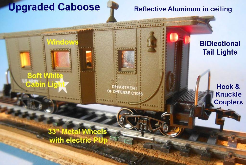
1 8 Tips and Tricks for Improving Rolling Stock Lighting ( Robert J. Wilkins Oct 2017) The following are some ideas and suggestions for improving the lighting in your HO rolling stock including passenger cars and cabooses. 1) Enhance Illumination: Use a strip of heavy duty aluminum wrap and glue to the ceiling of the cab to provide a reflective surface that will shed more light into the cabin. The interior of the cabin should be painted black to prevent the lighter color of the plastic from showing through. The cabin interior has been darkened with a black paint coat. Heavy Duty Aluminum is cut to the outline of the ceiling. Use adhesive putty (Tip 6) to stick the aluminum strip. Press onto the ceiling with the reflective side showing. 2) Install a slide or press-on/off switch to deactivate lights. With DCC constant track voltage around Volts lights in passenger cars and cabooses will stay on even when the car is in a siding. This will also occur in DC mode if the siding is powered. A simple solution is to add a slide switch to the undercarriage of the rolling stock by cutting one of the pickup leads. The photos below describe a process for adding a SPDT slide switch. A hole is cut in the floor of the car. I used a drill and Dremel cutting disc to cut out this rectangular hole. The switch is inserted and glued with CA (Super) Glue into place. One of the pickup leads is cut and soldered to the center and one pole of the switch.


2 3) Add Windows Some rolling stock comes without window panes included. These empty windows can be readily filled in using clear plastic material such as clear plastic protector sheets or from clear plastic packing material. Cut out a patch to a size larger than the window and glue in on the edges with liquid plastic glue. You can also use 2 pieces of clear adhesive tape stuck onto one another. One piece just larger than the window and the second larger than the first to provide adhesive at the edges for sticking to the wall around the window. Small panels of clear plastic are glued to the perimeter of the windows. Finished Window treatment. 4) How Many LEDs to use and what arrangement should be used? The LED Driver chip generates a constant 20 milliamps of current starting at 5 volts for the first LED. The chip is rated for a maximum voltage of 90 volts regulating the current output to 20 milliamps so the LEDs will not burn out. No resistors are required. The resistance of an LED has been calculated to be small around 13 ohms hence this is not a factor in changing voltage. What is important is the voltage drop generated by each LED, termed its forward Voltage, when added to a circuit. LEDs vary in their in their forward voltage drop. Yellow, Orange and Red LEDs have a forward voltage drop of around 2 volts while White, Blue and Green have a forward voltage drop of around 3.3 volts. When LEDs are arranged in series (ie Pos-Neg-Pos-Neg etc) for every LED added the required voltage to illuminate the circuit will rise by the forward voltage of the LED. For DCC operation, operating at between volts this would allow 3 to 4 LEDs to be used when arranged in a series circuit. (depending on forward voltage LEDs)
.")


 Most LEDs begin to light at around 10 milliamps.")


3 If using DC the threshold voltage for the LEDS to illuminate an in series setup would be too high (over 10 volts).if however the LEDS are arranged in parallel (ie Neg- Pos-Pos- Neg ) the voltage drop proves to be much lower. Three LEDs with the same forward voltage drop, set up in parallel, will require a threshold voltage around 1 volt higher than the initial voltage of 5 Volts required by the LED Driver chip. A total of 6.0 volts. To illustrate the 3 red LEDs (above) are set up in parallel. Using a regulated voltage the 3 red LEDS light up initially around 5.5 volts with good illumination around 6.0 Volts. The current reading is shown in the lower meter reading at 0.01 amps. (ie between 10 and 20 milliamps. ) Most LEDs begin to light at around 10 milliamps. If a LED of higher voltage drop is added into the parallel circuit it will not illuminate yet the others will. This is shown below. Why this occurs I am not sure. If someone has an explanation please let me know. It may be related to the difference in voltage drop. 2 Red LEDs + 1 White LED Set up in parallel. White does not light. 2 Red LEDs set in parallel + 1 White LED set in series. All LEDs Light This requires a higher threshold voltage (7.4V) and 20 mamps of current

 and put the other LED (White or Yellow) in series setup to the red LEDs.")

4 If this LED is added in series to the 2 parallel arranged LEDs it will light quite brightly at around 7 Volts. The voltage drop of the white LED explains a higher threshold voltage is required to light the circuit. Bottom line : The best circuit for DC use no more than 3 LEDs. If all are of the same type or have the same forward voltage they should be setup in parallel. If one of the LEDs has a higher Forward voltage use a parallel arrangement for the 2 LEDs (eg 2 red LEDs) and put the other LED (White or Yellow) in series setup to the red LEDs. Under these circumstances the lights should illuminate adequately at around 7 volts. Here is the circuit set up for the Caboose lighting system using either the Yellow or Soft white LED. The VB lead of the LED Driver unit connects to the Positive leads of the Red LEDs and the Negative lead from the White or Yellow LED connects to the Bridge Rectifier/Capacitor Negative Junction. This circuit works fine with DCC as well. Note : The Yellow LED will still work when connected in Parallel to the red LEDs as it has the same forward voltage drop. Setup for Caboose Lighting when using the Soft White LED 5) Use the new 2mm Red LEDs. 2mm LEDs are now available and the smaller size makes them more prototypical for HO scale rear lights. These 2 mm LEDs will now come standard with the Caboose lighting kit replacing the 3mm size. Because of the wider body shape they may require manipulation into place in the cabin. The forward voltage of these LEDs is around 2V.

.")


5 6) Use Blu Tack Putty for temporary adhesion. This putty like material is available under a number of names including (Blu Tack Brand- Adhesive Putty, Scotch Brand- Removable Mounting Putty, Loctite Brand - Fun Tack, Duck Brand Poster Putty). This is used as a versatile, malleable, reusable, temporary sticky adhesive. It is inexpensive and readily available in beige or blue from Stationary Stores, Home Stores, Arts and Craft Stores and Online. In this project it is used to attach weight plates to the rolling stock floor or install light circuit components and carriage interior seating and passengers. Blu Tack Putty is used here to secure metal weight to the floor of this caboose. Blu Tak Putty used here to secure the light circuit, the LED Driver Unit the carriage interior seating, passengers and weights. 7) The best location for the pickup wire hole. I have found that the best location for drilling the hole in the floor of the undercarriage is as close to the central pivot point of the truck but clear of the copper pickup collar. This allows for minimal lateral movement of the copper collar on the axle and tension on the wire and solder joint. Note here the pickup hole for the pickup wire has been drilled in the middle of the floor between the copper collar/axle and the central pivot point of the truck. This allows the truck to turn freely with minimal pulling on the collar. Make sure there is enough slack to allow gravity on the copper collar to make contact with the electrified axle. Also be sure that the insulated part of the wire is not rubbing against the collar preventing wheel rotation.


6 What if the truck cannot hold the second collar? : In this case simply use the other truck for the second collar. Here the coupling mechanism prevents the wiring of a collar to the front wheel of the truck. The collar is now placed on the other truck wheel to overcome this problem. 8) Add or Modify the Coupler You may wish to change the couplers of the Rolling stock from hook type to knuckle type couplers. You could also modify the hook type coupler to be compatible with the knuckle type. I have included a description on how this can be accomplished below. A You Tube video was produced by TrainTrackTrav that describes this process. "How to Make Clever Adaptor Coupler" : 1. Snip off the wing of the hook coupler 2. Optional: Snip off the downward pointing uncoupler or at least the pointed projection. 3. File down the hook to be compatible with the knuckle hook. 4. Once the trimming of the hook is compatible with the knuckle coupler hook, reattach the couplers to the car.
7
In this installment we will look at a number of things that you can do with LEDs on your layout. These will include:
 Introduction The first article in this series, LEDs 101 - The Basics, served to review the characteristics and use of LED lighting in a garden railway environment. It also generated a host of questions
This year Märklin have released a coach which has included LED lighting with a currentconducting close coupler (single pole)
") Hi All, Over the past few months I have been working at a steady pace to install LED lighting in my passenger coaches. The coach lighting must have LED lights to reduce power consumption on the layout
Hi All, Over the past few months I have been working at a steady pace to install LED lighting in my passenger coaches. The coach lighting must have LED lights to reduce power consumption on the layout
Tip: LED Lighting for the 4367 SBB Euro City Set, 4366 and 4368 Cars Date: , Corrections Modified , Photos
 Hi All, I have had the 4367 SBB Euro City set with extra cars 4366 and 4368 since 1998, apart from a test run on the layout they have stayed in storage ever since. I decided to change some rolling stock
Tip: LED Lighting for the 3098 Locomotive and 4392 Coach Set Date: , ,
 Hi All, Over the past few months I have been working at a steady pace to install LED lighting in my passenger coaches. The coach lighting must have LED lights to reduce power consumption on the layout
Tip: and Orient Express LED Light Upgrade Date: Correction
 Hi All, I have since inherited my friend Rudolf s 42755 Orient Express with the extra 42760 car set and wanted to complete the LED light upgrade as we had planned. Side view of the Restaurant car with
HOW TO MAKE YOUR OWN BATTERIES
 HOW TO MAKE YOUR OWN BATTERIES 1 Page TABLE OF CONTENTS Introduction....3 Usage....4 Aluminum Can Batteries/Cells....8 A Long Lasting, Yet Powerful Battery....10 PVC Pipe Batteries...13 Lab Notes....17
Upgrading Proto axle Geeps with Stewart Trucks. November 27, 2010 Mark Schutzer
 Upgrading Proto 2000 4 axle Geeps with Stewart Trucks November 27, 2010 Mark Schutzer Introduction Several years ago Proto 2000 made a bunch of 4 axle locomotives that used trucks that were a copy of an
Tip: 3425 Kittle Loco with LP4.0 Micro Conversion and LED Lighting Date: , Corrections Addition Link added
 Hi All, This is the last of Rudolf s LokPilot Micro V4.0 decoder conversions. He asked me to convert his Märklin Delta 3425 steam locomotive and wanted to improve the lighting effects for the cabin, change
Simple Free-Energy Devices
 Simple Free-Energy Devices There is nothing magic about free-energy and by free-energy I mean something which produces output energy without the need for using a fuel which you have to buy. Chapter 5:
Tip: 2856 LED Lighting for the Airport Express Set Date:
 Hi All, The 2856 Airport Express set was manufactured in 1983. On 09-11-1989 the locomotive was given a digital upgrade using a 6080 decoder. It has since had a digital upgrade to a high performance motor
PARTS IDENTIFICATION AND ASSEMBLY INSTRUCTIONS
 The U.S. M10 ammunition trailer was used mostly by armored units to transport additional ammunition. It could be towed by many different vehicles, including 2 ½ ton trucks, half tracks, armored cars, self-propelled
Owner s Manual: Standard Gauge Diesel shunter Locomotive in Gauge 3 scale. PLine. Built in Brass. Standard Gauge Shunter Locomotive Model (G3 scale)
") PLine Built in Brass Standard Gauge Shunter Locomotive Model (G3 scale) PLEASE READ THIS OWNERS MANUAL CAREFULLY BEFORE OPERATING THE MODEL Prototype Information: Not many Standard gauge locomotives operated
PLine Built in Brass Standard Gauge Shunter Locomotive Model (G3 scale) PLEASE READ THIS OWNERS MANUAL CAREFULLY BEFORE OPERATING THE MODEL Prototype Information: Not many Standard gauge locomotives operated
The H-MAC Heavy Metal Articulating Chassis Construction Guide
 The H-MAC Heavy Metal Articulating Chassis Construction Guide The Heavy Metal Chassis is constructed with two identical drive modules built using 10 mechanical sub-assemblies. The drive modules are integrated
Rigid Base / Turntable Bed. Exploded side view of bottom rotating wood drive wheel, showing optics aligned to stop bracket.
 TURNTABLE INDEXER #617 for use with BOWSER and other, turntables by 246 W. Main St. Leola, PA 17540 (717) 661-7041 www.dallee.com OVERVIEW The TURNTABLE INDEXER unit has been made with simplicity of installation
Application Note. Bachmann F40PH Tsunami Digital Sound Decoder Installation Notes
 Application Note Bachmann F40PH Tsunami Digital Sound Decoder Installation Notes Overview This application note describes how to install a TSU-AT1000 Digital Sound Decoder into a Bachmann HO F40PH. Skill
Tip: Liliput S LED Light for Forward Cabin Locomotive Date:
 Hi All, I obtained this Liliput locomotive catalogue number L131541-S some time ago and was disappointed that the feature of a steam locomotive with a forward driving cabin didn t have a detailed cabin
Tip: Difficult Conversions for F800 (3026) and 3111 Date: Led lighting added, LED Addition 3111
 and 3111 Date: Led lighting added, LED Addition 3111") Hi All, It s good to revisit previous conversions and see if you can improve on what has been done before. I decided to add LED lighting to my F800 (3026) and 3111. This document update shows how it was
Hi All, It s good to revisit previous conversions and see if you can improve on what has been done before. I decided to add LED lighting to my F800 (3026) and 3111. This document update shows how it was
72 Mustang Mach 1 tachometer cluster and gauge conversion
 72 Mustang Mach 1 tachometer cluster and gauge conversion Dated: 02-17-2009 (drafted by a Chevy person working on his first Ford -not good-) Revised: 11-05-2010 The following information pertains to how
PEOPLE ARE FAMILIAR WITH THE CONCEPT OF RUNNING A LIGHT FROM A BATTERY AND THEN RECHARGING THE BATTERY USING A SOLAR PANEL OR A WIND-POWERED GENERATOR
 A Perpetual Light PEOPLE ARE FAMILIAR WITH THE CONCEPT OF RUNNING A LIGHT FROM A BATTERY AND THEN RECHARGING THE BATTERY USING A SOLAR PANEL OR A WIND-POWERED GENERATOR. HOWEVER, WE REALLY WANT TO BE ABLE
Cabin Light. Hi All, 1
 Hi All, My friend Rudolf set me a challenge for his 36331 electric locomotive, wanting Telex couplers fitted. When I opened up the locomotive I discovered there is very little room to add extra components
6500DC Dual Motor Wireless Controller Kits
 6500DC Dual Motor Wireless Controller Kits READ ALL DIRECTIONS FIRST BEFORE PROCEEDING NOTE: SEE THE QUICK PROGRAM INSTRUCTIONS BEFORE OPERATING THE FIRST TIME. DO NOT REMOVE THE TRANSMITTER BATTERY Please
PYRTE. Building The Front Axle, Fork and Steering
 PYRTE Building The Front Axle, Fork and Steering The front axle on this traction engine is a very simple affair, in that it is a rectangular steel rod, sat on edge, with a pivot in the centre, which is
INSTRUCTIONS FOR PRODUCT: CAPX
 CONCEPT MODELS Web Address: http://www.con-sys.com Email: concept_models@con-sys.com 8331 Sheep Ranch Rd. Mountain Ranch, CA 95246 INSTRUCTIONS FOR PRODUCT: CAPX 1001 2 CONCEPT MODELS CAPX 1001 PARTS No.
Application Note. Atlas RS-3 Tsunami Digital Sound Decoder Installation Notes
 Application Note Atlas RS-3 Tsunami Digital Sound Decoder Installation Notes Overview This application note describes how to install a TSU-AT1000 digital sound decoder into an HO Atlas RS-3. Skill Level
Hi All, Update
 Hi All, With the success of my last Telex conversion on the 3704 locomotive I chose the 3796 tank locomotive to add Telex couplers controlled by a LokPilot 4 decoder. The locomotive does an un-coupling
Contents. Preparing the motor Winding the rotating secondary Winding the primary... 8
 120732-130389 Propeller Clock Construction Notes Revision E, December 2, 2013 Contents Preparing the motor... 2 Winding the rotating secondary... 5 Winding the primary... 8 UltiProp Clock (Elektor Dec.
Maglev. Track II. User Guide V0312
 Maglev Track II User Guide 60008 V0312 Materials Included Rolls of mounting tape 4 strip magnets 2 connector pins 2 track sections Items Needed (not included) Rubbing alcohol Soft cloths Utility knife
5 Amp Dual Mode Sound Decoder by Frank T.Verrico
 5 Amp Dual Mode Sound Decoder by Frank T.Verrico Model Rectifier Corp. s latest venture into O scale is a 5 amp. dual mode, [DC/DCC], sound decoder. This full featured N.M.R.A. compatible sound decoder
Tip: - Württemberg Era 1 Open Platform Cars LED Lighting Upgrade Date: , Photos
 Hi All, As I continue my LED light conversions of my rolling stock I have just completed all the Württemberg era 1 open platform cars I have which will make up four trains with eight cars per train. These
Building Tips by PMD For Wedico Trucks
 Building Tips by PMD For Wedico Trucks These are in no particular order but will help you with building! Below are some methods we have found to ease the assembly of these models. If you have any ideas
MODIFYING STANDARD LGB COUPLINGS FOR MAGNETIC DELAYED ACTION UNCOUPLING. By David Goldsworthy
 MODIFYING STANDARD LGB COUPLINGS FOR MAGNETIC DELAYED ACTION UNCOUPLING By David Goldsworthy THE APPLICATION I am in the process of constructing Gernise End the rural terminus of The Claptowte Railway.
General Information. Notations and Conventions. Compatibility Check. Kit Description. Call-Outs. Part Lists Great Plains Manufacturing, Inc.
 Part Lists Great Plains Manufacturing, Inc. 1 Installation Instructions Loup Shaft Monitor Used with Drill models: Compatible with most 1995 and later, two- and three-box drills with 5 8 -inch square main
DIY Synth Kit - Manual STUTTER SYNTH
 DIY Synth Kit - Manual STUTTER SYNTH Welcome to the DIY Synth - Manual This is a step-by-step guide to making your own electronic Synth. All you will need is your hands and your DIY Synth kit which includes
PFadvantage MF 6850/6855; Ideal 9080/9090
 MF 6850/6855; Ideal 9080/9090 Note: Indented items indicate parts included in an Quantity by Model assembly listed above MF Ideal Part Name/Description Part Number 6850 6855 9080 9090 Instruction Kit MF
The speaker soundbox improves the performance of the speaker in locos which have no purpose designed speaker cradle.
 1 1.OVERVIEW 8 pin DCC sound decoder with adjustable back-emf loco control. Fully adjustable sounds to match the chuff and whistle to the prototype loco. Provides a chuff which matches the loco speed and
Bachmann Digital Sound Decoder Installation Notes
 New Dimensions in Digital Sound Technology TM APPLICATION NOTE Bachmann 2-6-6-2 Digital Sound Decoder Installation Notes Overview This application note describes the installation of a DSD-090LC Digital
Triumph Street Triple VSM Grip Heater Install
 Triumph Street Triple VSM Grip Heater Install Introduction: With winter fast approaching and with painful memories of last winter riding with the club it was time to do something about getting some grip
SYSTEM OPERATION IMPORTANT CAUTIONS
 SYSTEM OPERATION The system is turned on by placing the gear shift lever in the reverse position. The green light on the cab Control Box will illuminate to indicate the system is operating. When an object
2. With the rear door open remove pull-style clip from the passenger side just below the door latch.
 LoD Offroad FJ Cruiser Rear Bumper with Tire Carrier Installation Instructions 1. Begin with removing factory spare from the rear door. 2. With the rear door open remove pull-style clip from the passenger
Tip: Water Crane with Servo Motor, LED Lantern, Moving Man Date: Update includes video
 Hi All, I ve had the Faller Swivel Water Spouts kit 120137 (B137 = old number) since 2000, which I will refer to as a Water Crane. I assembled the kit at the time with the intent of animating it with a
Application Note. Walthers/Proto 2000 E7A Tsunami Digital Sound Decoder Installation Notes
 Application Note Overview This application note describes how to install a TSU-1000 digital sound decoder into a Walthers/ Proto 2000 E7A. Skill Level 2: The entire installation can be completed in one
R-SE JK 4 DOOR Step Slider Install Instructions. *If any parts listed are missing or damages please call prior to install.
 R-SE JK 4 DOOR Step Slider Install Instructions Parts List: 1 Divers side slider assembly 1 Passenger side slider assembly 1 wiring harness 1 control box 2 spacers 2 LED lights (optional) 10 SS Button
Wiring Diagram 7 Amp 2 Step (7642MC) Ignition Box - No Booster ENGINE BLOCK LOWER LIMIT ARMING WIRE ORANGE GREEN BLACK DISTRIBUTOR LOOM (PRE-MADE)
 Ignition Box - No Booster ENGINE BLOCK LOWER LIMIT ARMING WIRE ORANGE GREEN BLACK DISTRIBUTOR LOOM (PRE-MADE)") Wiring Diagram 7 Amp 2 Step (7642MC) Ignition Box - No Booster IGNITION SWITCH 7 AMP 2 STEP TO TACH 7642MC LOWER LIMIT ARMING WIRE WHITE ENGINE BLOCK DISTRIBUTOR LOOM (PRE-MADE) DISTRIBUTOR COIL BATTERY
Wiring Diagram 7 Amp 2 Step (7642MC) Ignition Box - No Booster IGNITION SWITCH 7 AMP 2 STEP TO TACH 7642MC LOWER LIMIT ARMING WIRE WHITE ENGINE BLOCK DISTRIBUTOR LOOM (PRE-MADE) DISTRIBUTOR COIL BATTERY
Conversion of a Model A Ford Starter for 12 Volt operation. By Dick Harrell Gra-Neva A s
 Conversion of a Model A Ford Starter for 12 Volt operation By Dick Harrell Gra-Neva A s This presentation details converting a Model A starter for operation on a 12 Volt system. While a standard 6 volt
RECOMMENDED MOTOR AND BATTERY SET UP
 SPECIFICATION - Wingspan: 6000mm (236.2 in) - Length: 2873mm (113.1 in) - Flying weight: 14-18 kg - Wing area: 219.4 dm2 - Wing loading: 64g/dm2 - Wing type: HQ airfoils - Covering type: Genuine ORACOVER
Current Electricity. 3 rd Years
 Current Electricity 3 rd Years Comparing: Flow of electricity to flow of water. Electric Current An electric current is a flow of electric charge. An electric current is caused by the flow of electrons
TURBODYNO **WARNING**
 TURBODYNO **WARNING** It is dangerous to work in the vicinity of a lead-acid battery since they generate explosive gases during normal battery operation, To prevent an explosion when using a lead-acid
MF 9690, 9790, Challenger 660, 670
 Ag Leader Technology Parts List Note: Indented items indicate parts included in an assembly listed above Quantity by Model Part Name/Description Part No. MF 9690 MF 9790 Challenger 660 Challenger 670 Instruction
TL4076 Top 5 Tips Get to know your TL4076
 TL4076 Top 5 Tips Get to know your TL4076 Thermal Break with Teflon liner (behind fan) Hot End Assembly Fan Heat Block Extruder with toothed gear(brass) and idler (steel) Filament Guide Tube Nozzle Cable
CONCEPT MODELS WESTINGHOUSE SCHNABEL CAR 102/ Sheep Ranch Rd. Mountain Ranch, CA 95246
 CONCEPT MODELS http://www.con-sys.com//index.htm email:concept_models@con-sys.com 8331 Sheep Ranch Rd. Mountain Ranch, CA 95246 WESTINGHOUSE SCHNABEL CAR 102/301 2 CONCEPT MODELS Foreword As our name implies
EMD DD35 Powered & Dummy Units. Assembly Instructions
 EMD DD35 Powered & Dummy Units Assembly Instructions Main Shell Side Handrail End Handrails Fuel Tank (Loose Part, Powered Unit Only) Side Handrail End Handrails 2 No. MT N Scale Body Mount Coupler Shorten
INSTALLATION INSTRUCTIONS FORD POWERSTROKE PICKUPS MODEL YEAR
 p p INSTALLATION INSTRUCTIONS FORD POWERSTROKE PICKUPS MODEL YEAR 2005-2006 www.dieselturbolifesaver.com Diesel Turbo Lifesaver (DTLS) is a computer controlled device that allows you to set an automatic
PAPER ASSIGNMENT #1: ELECTRIC CIRCUITS Due at the beginning of class Saturday, February 9, 2008
 PHYS 591 - Foundations of Science II By Richard Matthews PAPER ASSIGNMENT #1: ELECTRIC CIRCUITS Due at the beginning of class Saturday, February 9, 2008 Part I; Outline of the important elements of the
Los Angeles Model Railroad Society. Wiring A Tortoise Switch Machine for the Mainline
 Los Angeles Model Railroad Society Wiring A Tortoise Switch Machine for the Mainline Ira Abramowitz 2/27/2010 1 INTRODUCTION...3 1.1 LET S START...3 2 MECHANICAL MOUNTING...4 2.1 MECHANICAL MOUNTING OPTIONS...4
3. Each car must have a front brass weight(s) as made by the chassis manufacturer for that specific chassis.
 as made by the chassis manufacturer for that specific chassis.") GRAVITY CLASS RULES 1. Cars must be brass weighted, inline motor chassis manufactured by BSRT, Slottech, or Wizzard High Performance. Eligible chassis include the V1, BSRT G3, G3R or G3RS, Slottech Panther
GRAVITY CLASS RULES 1. Cars must be brass weighted, inline motor chassis manufactured by BSRT, Slottech, or Wizzard High Performance. Eligible chassis include the V1, BSRT G3, G3R or G3RS, Slottech Panther
TONY S TECH REPORT. Basic Training
 TONY S TECH REPORT (Great Articles! Collect Them All! Trade them with your friends!) Basic Training OK YOU MAGGOTS!! Line up, shut up, and listen good. I don t want any of you gettin killed because you
Wheel Angle Sensor Kit Installation
 Wheel Angle Sensor Kit Installation Item Component Part Number Qty 1. Bracket Kit, WAS 200-0081-02 1 2. WAS Assembly 200-0468-01 1 3. Instruction Guide 602-0398-01 1 602-0398-01 REV A 2014-02 Overview
Wind Tunnel User Guide V0814
 Airtech X-Stream Wind Tunnel User Guide 57889 V0814 The Airtech X-Stream Wind Tunnel by Pitsco features adjustable speed and runs quietly. Quality-made and designed for accuracy, the versatile X-Stream
Cable Car. Category: Physics: Balance & Center of Mass, Electricity and Magnetism, Force and Motion. Type: Make & Take.
 Cable Car Category: Physics: Balance & Center of Mass, Electricity and Magnetism, Force and Motion Type: Make & Take Rough Parts List: 1 Paperclip, large 2 Paperclips, small 1 Wood stick, 1 x 2 x 6 4 Electrical
I n s t r u c t i o n M a n u a l. Instruction Manual SPECIFICATION
 I n s t r u c t i o n M a n u a l Instruction Manual SPECIFICATION - Wingspan: 3200mm (125,9 in) - Length: 1650mm (64,9 in) - Flying weight: 3000gr 3200gr - Wing area: 64.5 dm2 - Wing loading: 46g/dm2
Switch Machines Installation & Wiring
 Switch Machines Installation & Wiring Conventional Twin Coil Switch Machines Electrically: In use since developed by Walthers in early 1930 s Long time standard for remote operation Currently: Rix, Atlas,
Rostra Electronic Cruise Control Install On a Stratoliner or Roadliner
 Rostra Electronic Cruise Control Install On a Stratoliner or Roadliner MATERIALS LIST: 1 - Rostra Part # 250-1223 (www.brandondist.com/products/cruise1223.htm) 1 - Signal Splitter part # 250-4369 1 - Engagement
BXD Battery Disconnect
 INSTALLATION MANUAL BXD Battery Disconnect Installation Manual BATTERY DISCONNECTS provides a simple and safe means of disconnecting the coach and chassis battery(s) of an RV. With just the touch of a
The Da-Lite Difference.
 The Da-Lite Difference. Instruction Book for Boardroom Electrol DA-LITE SCREEN COMPANY, INC. 3100 North Detroit Street Post Office Box 137 Warsaw, Indiana 46581-0137 Phone: 574-267-8101 800-622-3737 Fax:
Hornby 08 Diesel Shunter EM Finescale Conversion.
 Hornby 08 Diesel Shunter EM Finescale Conversion. Before you start, it is a good idea to have some small containers or snap top poly bags to put screws and components in for safe keeping...much better
Sensors W2 and E2 are optional. Installation guide, 'Pickle Fork' Back-and-Forth Model Train Controller
 Installation guide, 'Pickle Fork' Back-and-Forth Model Train Controller Azatrax model PFRR-NTO This controller can automate a single track 'back-and-forth' model train layout -- or, one train can travel
LEDneon flex. Features & Benefits DOT-FREE ILLUMINATION
 DOT-FREE ILLUMINATION Features & Benefits Viable alternative to glass neon 220V with power converter 12V DC with constant voltage driver Seamless, dot-free illumination Up to 80% more energy efficient
Table of Contents. Tail Wheel Assembly Installation.. page 01. Stabilizer Installation.. page 02. Fin Installation.. page 03
 Table of Contents Tail Wheel Assembly Installation.. page 01 Stabilizer Installation.. page 02 Fin Installation.. page 03 Elevator and Rudder Hinge Installation.. page 04 Rudder Controls.. page 05 Elevator
6000DC CONTAINS TRANSMITTER AND RECEIVER BOX ONLY
 READ ALL DIRECTIONS FIRST BEFORE PROCEEDING 6000 DC SINGLE MOTOR CONTROLLER WITH EXTRA OPTION KITS. NOTE THE TRANSMITTER HAS BEEN PROGRAMMED, please follow programming directions only if you need to reprogram.
STAY ON TRACK WITH THIS LINE FOLLOW BUGGY WITH :MOVE LINE FOLLOW BOARD FOR BBC MICRO:BIT
 STAY ON TRACK WITH THIS LINE FOLLOW BUGGY WITH :MOVE LINE FOLLOW BOARD FOR BBC MICRO:BIT BUILD INSTRUCTIONS LIST OF FIXINGS M3 BOLTS M3 NUTS STANDOFFS 6mm x12 x4 x4 10mm x4 x12 12mm x2 30mm x2 20mm M-F
A device that measures the current in a circuit. It is always connected in SERIES to the device through which it is measuring current.
 Goals of this second circuit lab packet: 1 to learn to use voltmeters an ammeters, the basic devices for analyzing a circuit. 2 to learn to use two devices which make circuit building far more simple:
Installation Instructions PowerBoard Automatic Retracting Running Board
 Installation Instructions PowerBoard Automatic Retracting Running Board Vehicle Application Chevy Silverado/GMC Sierra Extended Cab Diesel 2011 and newer Part Number: 75147-15 Chevy Silverado/GMC Sierra
AUXILIARY BATTERY BOX INSTALLATION INSTRUCTIONS
 AUXILIARY BATTERY BOX INSTALLATION INSTRUCTIONS The original TOMMY GATE hydraulic lift Assembling the Auxiliary Battery Box 1. Remove the cover from the auxiliary battery box by removing the two nuts and
MONGOOSE. Introduction. < blueroomelectronics > Assembly Instructions. Mongoose was designed as an introduction to Mechatronics.
 MONGOOSE Assembly Instructions Introduction Mongoose was designed as an introduction to Mechatronics Page 1 of 12 Before you start The Mongoose is a complex kit and skipping instructions is not advised,
650 Series Cargo Van Lift Mounting Instructions Fullsize Ford 1992-Present
 TOMMY GATE OWNER'S / OPERATOR'S MANUAL 650 Series 650 LB Capacity 650 Series Cargo Van Lift Mounting Instructions Fullsize Ford 1992-Present Installing the Base Plate 1. Examine the interior and exterior
Circuit Basics and Components
 Circuit Basics Electric circuits are arrangements of conductors and components that permit electrical current to flow. A circuit can be as simple as a battery and lamp or as sophisticated as a computer.
INSTALLATION INSTRUCTIONS
 Rear Vision System Tailgate Emblem Camera Mirror Display 2009-Current Ford F-150 and 2010-Current Super Duty (Kit part number 1008-9527) Kit Contents: Mirror Tailgate Emblem Mount with Camera Interior
GENERAL AND PLANNING INFORMATION
 SOLAR CAR NO SOLDER CONTENTS: Section 1: General and Planning Information Section 2: Components and Material Required Section 3: Construction Section 4: Wiring Section 5: Testing Section 6: Theory DESCRIPTION
Permanent Magnetic Linear Generator Project Prototype (This Material was Produced by Oregon State University s Energy Systems Group)
") Permanent Magnetic Linear Generator Project Prototype (This Material was Produced by Oregon State University s Energy Systems Group) This Permanent Magnet Linear Generator (PMLG) prototype was developed
Permanent Magnetic Linear Generator Project Prototype (This Material was Produced by Oregon State University s Energy Systems Group) This Permanent Magnet Linear Generator (PMLG) prototype was developed
Ag Leader Technology. Combine Installation New Holland TC 57, 59. Monitor Installation
 Monitor Installation Figure 1. Monitor installed on right side cab window using window mount bracket. 1. If you are in very humid conditions where moisture may condense on the glass where you are mounting
Wheel Angle Sensor Kit Installation
 Wheel Angle Sensor Kit Installation Item Component Part Number Qty 1. Bracket Kit, WAS 200-0540-01 1 2. WAS Assembly 200-0468-01 1 3. Instruction Guide 602-0390-01 1 602-0390-01 REV A 2014-02 Overview
Repair of warped dial scale - Sony CRF-5090.
 Repair of warped dial scale - Sony CRF-5090. Apparently this is quite a common problem with this series of receivers. This one was bought on a local auction site where it was clearly advertised as having
The rod and the cloth both become charged as electrons move between them.
 1 polythene rod is rubbed with a cloth. polythene rod cloth The rod and the cloth both become charged as electrons move between them. The rod becomes negatively charged. Which diagram shows how the rod
ASSEMBLY INSTRUCTIONS FOR NEW FK109 4 LED Railroad Crossing Flasher Kit WITH ADJUSTABLE FLASHING SPEED CONTROL with 4 Red 3mm Leds
 ASSEMBLY INSTRUCTIONS FOR NEW FK109 4 LED Railroad Crossing Flasher Kit WITH ADJUSTABLE FLASHING SPEED CONTROL with 4 Red 3mm Leds Description: Very easy to build, The FK109 Led Flasher kit makes the perfect
Walthers/Life-Like USRA Steam Locomotive
 North Raleigh Model Railroad Club Installing Decoders in N Scale Locomotives Detailed Instructions Walthers/Life-Like USRA 2-8-8-2 Steam Locomotive by David Derway May 17, 2010 Table of Contents Introduction...
The POWER. In PRESENTATION PRODUCTS. Instruction Book for BOARDROOM ELECTROL DA-LITE SCREEN COMPANY, INC.
 The POWER In PRESENTATION PRODUCTS Instruction Book for BOARDROOM ELECTROL DA-LITE SCREEN COMPANY, INC. 3100 North Detroit Street Post Office Box 137 Warsaw, Indiana 46581-0137 Phone: 574-267-8101 800-622-3737
Voltmeter. for Experiments with the fischertechnik Expansion Kit. Order No
 Voltmeter for Experiments with the fischertechnik Expansion Kit Order No. 30083 Fischer Werke 7241 Tumlingen Printed in Germany Ref. No. 33-8/70/5 2. Operation of the Moving Coil Meter If a current flows
INTELLIQUILTER INSTALLATION ON APQS MILLENNIUM/FREEDOM SR ON BLISS-READY TABLE VERSION
 INTELLIQUILTER INSTALLATION ON APQS MILLENNIUM/FREEDOM SR ON BLISS-READY TABLE VERSION 02.24.14 1. THREAD BREAK DETECTOR Position the thread break detector on the top of the arm, so the hole in the bracket
General Purpose Flasher Circuit
 General Purpose Flasher Circuit By David King Background Flashing lights can be found in many locations in our neighbourhoods, from the flashing red light over a stop sign, a yellow warning light located
Photo below shows the yellow wire on the left and the black on the right.
 2000 pound lift installation photos and troubleshooting helps This photo shows a wired lift. Shown in this photo User will install: From the control cable: small blue wire on front solenoid terminal small
- MK7 Mirror Integration Kit - Installation Instructions
 - MK7 Mirror Integration Kit - Thank you for choosing the Double Apex Gentex Mirror Integration kit for your Volkswagen MK7. If you have any questions about the installation please email us at support@dblapex.com.
Smart Switch Basic Kit - 24 volt ( ) Wiring Instructions
 Wiring Instructions") Smart Switch Basic Kit - 4 volt (54-08) Wiring Instructions NB 8/0/ 6 ga. wire 6 ga. wire 6 ga. wire OUT IN 6 ga. wire Yellow Black Blue 50 AMP BREAKER MOTOR 6 ga. wire 6 ga. wire 6 ga. wire ROCKER SWITCH
Smart Switch Basic Kit - 4 volt (54-08) Wiring Instructions NB 8/0/ 6 ga. wire 6 ga. wire 6 ga. wire OUT IN 6 ga. wire Yellow Black Blue 50 AMP BREAKER MOTOR 6 ga. wire 6 ga. wire 6 ga. wire ROCKER SWITCH
Mounting a Garmin to an R1150R Motorcycle
 Mountain a Garmin GPS on your BMW Motorcycle Introduction The following document will describe how I mounted my Garmin 1490T GPS unit to my motorcycle. Garmin makes a specific GPS unit (the Zumo) for motorcycles
Installation Instructions Supertop for Truck
 Installation Instructions Supertop for Truck US Patent 6827391 Vehicle Application: Ford F150 1987-1996 (8 ft.) Part Number: 76315 Ford F250 1987-1998 (8 ft.) Part Number: 76315 Ford F350 1987-1998 (8
Go-ped ESR750 / ESR750EX Rear Brake Installation Instructions
 Go-ped ESR750 / ESR750EX Rear Brake Installation Instructions This kit provides all the parts you need to install a rear brake on your ESR750 or ESR750EX. It will not work on an ESR Sport, or other Go-ped
Right On Replicas, LLC Step-by-Step Review * Mack Fire Pumper 1:32 Scale Revell Model Kit # Review
 Right On Replicas, LLC Step-by-Step Review 20150915* Mack Fire Pumper 1:32 Scale Revell Model Kit #85-1945 Review The Mack CF600 Pumper is a familiar fire truck that is still widely used in firehouses
Installation Tips for RS1 + EVO-RIDE + SPDT. *(reglar key, automatic transmission vehicles ONLY)*
*") Installation Tips for RS1 + EVO-RIDE + SPDT TIP SHEET T1235 *(reglar key, automatic transmission vehicles ONLY)* Thank you for purchasing your remote start from MyPushcart.com - an industry leader in providing
Installation Tips for RS1 + EVO-RIDE + SPDT TIP SHEET T1235 *(reglar key, automatic transmission vehicles ONLY)* Thank you for purchasing your remote start from MyPushcart.com - an industry leader in providing
The Starter motor. Student booklet
 The Starter motor Student booklet The Starter motor - INDEX - 2006-04-07-13:20 The Starter motor The starter motor is an electrical motor and the electric motor is all about magnets and magnetism: A motor
PRO-CAMEL 24 SETUP AND OPERATING INSTRUCTIONS
 PRO-CAMEL 24 SETUP AND OPERATING INSTRUCTIONS CAMEL MINING PRODUCTS Inc. P.O. Box 3179 Quartzsite AZ 85346 Telephones 1-800-331-5311 or 1-928-927-4009 FAX 1-928-927-4739 email desfox@tds.net ... DRIVE
Rear Vision System Tailgate Emblem Camera Aftermarket Display 2009-Current Ford F-150 and 2010-Current Super Duty (Kit part number )
") Rear Vision System Tailgate Emblem Camera Aftermarket Display 2009-Current Ford F-150 and 2010-Current Super Duty (Kit part number 1008-6509) Kit Contents: Tailgate Emblem Mount with Camera Chassis Harness
Rear Vision System Tailgate Emblem Camera Aftermarket Display 2009-Current Ford F-150 and 2010-Current Super Duty (Kit part number 1008-6509) Kit Contents: Tailgate Emblem Mount with Camera Chassis Harness