United States Patent (19) 11 Patent Number: 4,465,446. Nemit, Jr. et al. (45) Date of Patent: Aug. 14, 1984
|
|
|
- Jack Chapman
- 5 years ago
- Views:
Transcription
1 United States Patent (19) 11 Patent Number: 4,4,446 Nemit, Jr. et al. () Date of Patent: Aug. 14, 1984 (54) RADIAL AND THRUST BEARING 3,4,313 7/1969 Lohneis a on - a a a a 8/236 MOUNTINGS PROVIDING INDEPENDENT 3,719,440 3/1973 Snider... LOADING 3,804,562 4/1974 Hansson as 4,168,869 9/1979 Stephan... 8/174 (75) Inventors: Paul Nemit, Jr., Waynesboro, Pa.; Joseph W. Pillis, 8& H town, Md. Primary ry Examiner-Leonard E. Smith w op 1IIIs, tilagerstown Assistant Examiner-Jane E. Obee 73) Assignee: Frick Company, Waynesboro, Pa. Attorney, Agent, or Firm-Dowell & Dowell 21 Appl. No.: 493, ABSTRACT 22 Filed: May 11, 1983 A radial and thrust bearing mounting particularly 51) Int. Cl.... F01C1/16 adapted for a helical screw type compressor, is pro 52 U.S. Cl /1; 8/174 vided in which the radial load is isolated from the thrust 58 Field of Search /1, 2, 3; load to prevent the thrust bearing from carrying any 8/174, 176, 189 A substantial radial load, and in which adjustment of the (56) Ref Cited axial discharge end clearance between the faces of the eferences lie U.S. PATENT DOCUMENTS 2,111,568 3/1938 Lysholm... 48A2O1 3,388,854 6/1968 Olofsson /3 4 Claims, 1 Drawing Figure rotors and the discharge end of the housing cover is provided. t ass 2N e S. -m N. 22% bsne 2 m m 2EN N ESSEYZZZsity 7 EN >s.. SNSS7 É16.N. SN EZ3 ans Nial 68
2

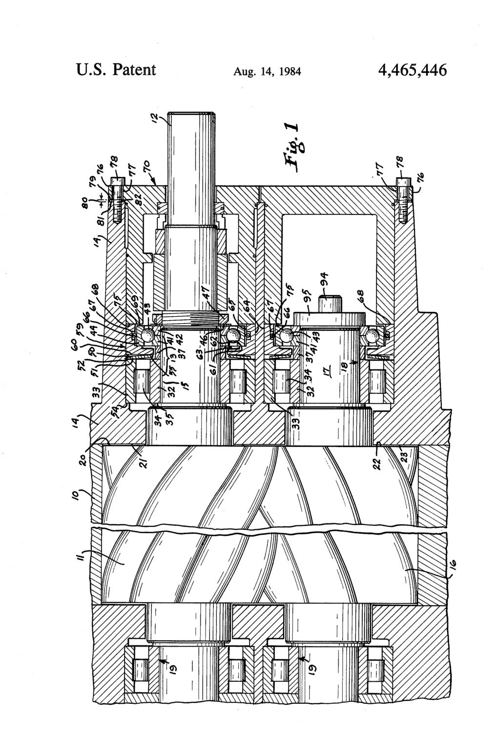
3 1. RADAL AND THRUST BEARING MOUNTINGS PROVIDING INDEPENDENT LOADING BACKGROUND OF THE INVENTION The invention relates to anti-friction mountings for rotating shafts and more particularly to a mounting for carrying the axial and radial load of a compressor of the helical screw type. In a compressor of this type having a driven male rotor intermeshing with a female rotor the compression of the fluid between the rotors results in a high load in an axial direction. Thus in compressors of this type a thrust bearing has been used on each rotor shaft to maintain the rotors at a fixed noncontacting position between the end covers and to absorb the axial load. See for example, the patent to Lysholm U.S. Pat. No. 2,243,874. A problem associated with the use of an axial thrust bearing independent of the radial load bearing, in the prior art, has been the absorption of some of the radial load by the thrust bearing. This subjects it to a type of load for which it is not designed and can lead to a mal function or shortened life. Furthermore, in a helical compressor of the type under consideration the clearance between the end faces of the rotors and the discharge end of the housing is critical as a determinate of the performance of the compressor. Various kinds of bearing mountings for both radial and axial loads have been used heretofore in which an attempt has been made to compensate for the differ ences in the loadings. Breckheimer U.S. Pat. No. 4,119,392 discloses a screw compressor with a short axially shiftable rotor carried by a roller bearing and an axially displaceable bearing which is directly engaged by a piston, the oper ation of which controls the position of the rotor. The patent to Langner, U.S. Pat. No. 3,738,719, dis closes a preloaded bearing in which a spring produces a preload value against the outer races of a coaxial bear 1ng. Hanson, U.S. Pat. No. 1,399,959 employs a compress ible material instead of a spring with adjustment for preloading. The German patent, No. 2,807,411 of 1978, discloses a bearing providing for preloading and rotor expansion. Witte, U.S. Pat. No. 1,161,570 discloses a bearing mounting for use in line shaft hangers of different types. Roggenburk, U.S. Pat. No. 2,762,340, employs a two row ball set at each end for providing both radial and axial centering, in which each carries a portion of both loads. Stoica, U.S. Pat. No. 3,429,228, employs a single-row ball bearing at each end to take the radial and thrust load, claiming thereby elimination of thrust bearings. Schibbye, U.S. Pat. No. 3,467,0, discloses a helical screw type compressor with male and female rotors and which employs the thrust of the low pressure helical screws to counterbalance the thrust of the high pressure helical screws of a two stage compressor, and thus elim inate any heavy thrust load. Centering is obtained by thrust collars. Ware, U.S. Pat. No. 3,528,757, employs an adjustable thrust collar to center the rotor. Snider, U.S. Pat. No. 3,719,440, employs a Belleville type spring to provide preloading of two single-row 4,4,446 5 O 2 radial bearings which handle both radial and thrust loads. Hansson, U.S. Pat. No. 3,804,562, has a single-row radial bearing at one end of a shaft which is adjustable for centering of the rotor. At the opposite end of the shaft is another single-row ball bearing with the inner race positioned by a Belleville type spring, thus causing a preloaded thrust centering of the rotor, with both bearings carrying equal axial and thrust loading. Beavers, U.S. Pat. No. 4,033,647, discloses thrust bearings which carry the vertical shaft loading. The bottom bearing carries a predetermined load and when the load is exceeded the top bearing carries the excess. Radial loading is insignificant and is carried by sleeves. Lohneis, U.S. Pat. No. 3,4,313, discloses force pre loading of a radial load carrying bearing and tapered thrust rings to compensate for shaft temperature changes and other axial loading. The single-row bear ings must carry the axial load up to the limits of expan sion of the thrust rings. SUMMARY OF THE INVENTION It is an object of the present invention to provide a mounting for the shafts of a helical screw type compres sor which not only carries the radial load, but also carries the axial load so that the axial load bearing is subjected only to the axial load, not to any substantial radial load, and in which resilient means is included in the mounting so that the critical clearances at the dis charge end between the end faces of the rotors and the discharge end cover may be externally observed and easily adjusted and maintained. This is accomplished by mounting the thrust bearing so that its inner race is rigidly held on the shaft and its outer race is spaced from the assembly except on one inward face where it engages a carrier which bears against a Belleville spring, and in which the carrier is engaged by the end cover which is in fixed, predeter mined, spatial relationship to the housing so that the axial position of the shafts, and hence, the clearances, are provided. Further objects of the invention will become appar ent from the following description in conjunction with the accompanying drawing. BRIEF DESCRIPTION OF THE DRAWING FIG. 1 is a section of a bearing assembly in accor dance with the present invention illustrating its associa tion with the rotors and the discharge end housing and COWer. DESCRIPTION OF THE PREFERRED EMBODIMENT With further reference to the drawing, there is illus trated an end portion 10 of the housing of a compressor of the helical screw type having a male rotor 11 carried by a drive shaft 12 which is supported at the discharge end by a bearing assembly 13 carried by a discharge cover 14 that is fixed to the housing. The male rotor 11 intermeshes with female rotor 16 having a shaft 17 which is supported by bearing assen bly 18, similar to bearing assembly 13, and which is carried by the discharge end cover 14. At their remote ends, adjacent to the inlet, not shown, the shafts are carried by conventional bearing assemblies 19. As is well known in the art, at the discharge end of any dual rotor screw compressor it is necessary to main tain a close running clearance between the male rotor

4 4,4,446 3 discharge end and the face 21 of the cover 14, and also between the female rotor end face 22 and the end face 23 of the cover 14. In the past a thrust bearing has been used to maintain the axial position of the rotors and to absorb the axial thrust load which results from the compression of the fluid between the rotors, but such thrust bearings have been subject to some radial load. The present invention, as will be described, isolates the radial and thrust loads so that the thrust bearing substantially carries only a thrust load. The bearing assembly 13 includes a roller bearing for proper diametrical clearance and having inner and outer races 32 and 33, and roller 34. At its inward end, nearer to the rotors, the inner race 32 abuts a shoulder on the shaft 12. At its outward end the inner race 32 abuts a spacer 37 which at its other end abuts a first section 41 of the inner race of a thrust bearing, said bearing having a second inner race section 42, balls 43, and an outer race 44. The race section 42 is engaged by locking ring 46, held by nut 47 which is threaded onto shaft 12 and tightened against the locking ring, thrust bearing inner race sections 42 and 41, spacer 37, and inner race 32 against shoulder of the shaft 12, thereby making these parts a rigidly fixed unit rotating with the shaft 12. Radially outwardly of the spacer 37 of the aforemen tioned rigid unit a Belleville spring is positioned so that an outer portion 51 engages an outward face 52 of the outer race 33 of the roller bearing assembly. The inward face 53 of the outer race 33 engages the inner shoulder 54 of the end cover 14. The inner portion of the Belleville spring engages a bearing carrier 59 at its inward face 60. The bearing carrier 59 has a substantially L-shaped cross section and has an inside face 61 which engages the inward face 62 of the outer race of the thrust bear ing. The leg of the bearing carrier extending radially inwardly has a recess 63 for the purpose of avoiding contact with the inner race of the thrust bearing. The bearing carrier has an outer periphery 64 which engages the cover 14 and an inner periphery which is spaced from the outer periphery of the outer race 44 of the thrust bearing sufficient to avoid contact because of permissible radial movement in bearing assembly. In the clearance space provided an O-ring 66 is car ried in a groove 67 in the inner wall of the bearing carrier. The O-ring is a relatively close fit for nonspin ning purposes but is sufficiently compressive so as to avoid exerting pressure on the outer race of the thrust bearing. The outward face 68 of the axially extending leg of the bearing carrier is axially spaced from the face 61 in order to extend outwardly of the outer face 69 of the outer race 44 of the thrust bearing. With the assembly thus far described it will be appar ent that with a predetermined axial length of the spacer 37 and of the distance between the faces 61 and 68 of the bearing carrier 59, tightening of the nut 47 will result in compressing the Belleville spring causing the shaft and the fixed unit rotating with it to move into a position in which the face of the end of the rotor 11 engages the face 21 of the housing cover. In order to fix the assembly in place and with a space between the faces and 21 a shaft seal enclosure or end cover 70 is mounted internally of the discharge end housing cover 14 and pulled into contact at its inward face 75 with the face 68 of the bearing carrier 59. It will be noted that the inward face 75 is spaced from the outer face 69 of the outer race of the thrust bearing due to the aforementioned length of the axially extending leg of the spacer 37. The end cover 70 has an outer rim portion 76 with openings 77 through which bolts 78 extend for engagement with the cover 14. The radially inner portion of the end cover is of a suitable configura tion to receive the shaft 12 and has appropriate sealing means well known in the art. The end cover 70 on the inward face 79 of its rim is constructed and dimensioned so that when the cover is initially pulled into. contact by the bolt 78 with its in ward face 75 engaging the face 68 of the bearing carrier 59 there will be a small gap 80 between the rim 76 and the face 81 of the cover 14. By reducing this gap 0.005"to 0.007'( mm) the inward axial movement against the Belleville spring further con presses it and produces similar inward movement of the rotor and shaft assembly to provide a similar clearance between the faces and 21. The desired axial length of gap is fixed by inserting a shim 82 in such space of a thickness corresponding to the reduced length of the gap. Shaft 17 of the female rotor 16 has the same type of radial and thrust bearing assembly as shaft 12 of the male rotor. Shaft 17 has a locking bolt 94 and plate 95 which take the place of and serve the same purpose as the nut 47 on shaft 12. The inward face 75 of the end cover 70 engages the corresponding bearing carrier for the shaft 17, as described above. The Belleville springs have a load rating such that the highest running compressor discharge pressure will not cause a further compression thereof, thus retaining the clearances between the faces and 21, and 22 and 23, as provided at the time of assembly. As a result of the bearing structure and arrangement described the thrust bearings are subjected substantially only to axial load and the clearance at the discharge end of the compressor may be inspected and maintained. We claim: 1. In a bearing assembly including a radial bearing having inner and outer races, and a thrust bearing hav ing inner and outer races, fixed in spaced relation on a shaft, and a housing around said bearing assembly, the improvement comprising, said housing carrying said radial bearing by means of mounting its outer race, carrier means overlying and radially spaced from the outer race of said thrust bearing, said carrier means extending into the space between the outer races of said radial and said thrust bearing and engaging an inward wall of the outer race of said thrust bearing, compress ible means between the outward wall of said carrier means and the inward wall of the inner race of said radial bearing, and means coaxial with said shaft hold ing said carrier means, said compressible means, and said radial bearing outer race means in fixed relation ship, whereby the carrying of radial load by said thrust bearing is substantially eliminated. 2. The invention of claim 1, in which said means coaxial with said shaft is fixed to said housing in spaced relation, thereby axially positioning said shaft with re spect to said housing. 3. A helical screw type compressor having cooperat ing rotors within a housing and a discharge port at one end of the housing, said rotors having shaft means and discharge end walls, a bearing assembly carrying each shaft means, cover means having an inner wall and carrying the bearing assembly, said cover means having a face in facing relation to said discharge end walls of said rotors, said cover means and said housing being in

5 5 fixed relationship, said bearing assembly comprising radial bearing means mounted on the shaft means and having outer race means in fixed relation with said cover means, thrust bearing means mounted on the shaft means and having inner and outer race means, means fixing the inner race means of said thrust bearing means, and the inner race means of said radial bearing means in spaced unmovable relationship on said shaft means, Belleville spring means around said shaft means and having a first portion engageable with the outward end of the outer race means of said radial bearing means, a bearing carrier of substantially L-shaped cross section engaging the inner wall of said cover means, said carrier having a first portion with an inward face engaging said Belleville spring means and a second portion around and spaced from said thrust bearing means, said bearing carrier first portion having an outward face engaging the outer race means of said thrust bearing means, said first portion being spaced from the inner race means of said thrust bearing means, end cover means having a rim portion extending over the outer end of the cover means and a body portion extending inwardly of said cover means and into engagement with the outward end of said bearing carrier, and means for securing the end cover means in spaced relation with the cover means and thereby exerting a force in a direction parallel to the axis of the shaft means against said bearing carrier whereby said shaft means are moved and the rotors' end walls are spaced a desired distance from said cover face and whereby the radial loads of the shafts are carried only by the radial bearing means and not transmitted to the thrust bearing means. 4. A helical screw type compressor having cooperat ing rotors within a housing and a discharge port at one end of the housing, said rotors having shaft means and discharge end walls, a bearing assembly carrying each shaft means, cover means having an inner wall and carrying the bearing assembly, said cover means having a face in facing relation to said discharge end walls of said rotors, said cover means and said housing being in fixed relationship, said bearing assembly comprising radial bearing means with inner race means mounted on the shaft means and outer race means engaging the 4,4, cover means, said outer race means having an inward end in fixed relation with said cover means, spacer means around the shaft means and engageable with the outward end of said inner radial bearing means inner race means, thrust bearing means around the shaft means and having inner and outer race means, the in ward end of the inner race means engageable with said spacer means, fastener means engageable with said shaft means and engageable with the outward end of the inner race means of said thrust bearing means, whereby said fastener means may hold the inner race means of said thrust bearing means, said spacer means, and the inner race means of said radial bearing means together in fixed unmovable relationship on said shaft means, Belleville spring means around said spacer means and having a first portion engageable with the outward end of the outer race means of said radial bearing means, a bearing carrier of substantially L-shaped cross section engaging the inner wall of said cover means, said carrier having a first portion around and spaced from said spacer means and a second portion around and spaced from said thrust bearing means, said bearing carrier first portion having an inward face engaging said Belleville spring means and an outward face engaging the outer race means of said thrust bearing means, said first por tion being spaced from the inner race means of said thrust bearing means, whereby said fastener means in holding position may cause said shaft means to move so that said rotor end walls engage said cover face, end cover means, said end cover means having a rim portion extending over the outer end of the cover means and a body portion extending inwardly of said cover means and into engagement with the outward end of said bear ing carrier, and means for securing the end cover means in spaced relation with the cover means and thereby exerting a force in a direction parallel to the axis of the shaft means against said bearing carrier whereby said shaft means are moved and the rotors' end walls are spaced a desired distance from said cover face and whereby the radial loads of the shafts are carried only by the radial bearing means and not transmitted to the thrust bearing means. sk k sk
(12) United States Patent
 United States Patent") USOO7654162B2 (12) United States Patent Braaten (54) DEVICE FOR INSTALLATION OF A PROBE AND PROBEACCOMMODATING ARRANGEMENT (75) Inventor: Nils A. Braaten, Trondheim (NO) (73) Assignee: Roxar ASA, Stavanger
USOO7654162B2 (12) United States Patent Braaten (54) DEVICE FOR INSTALLATION OF A PROBE AND PROBEACCOMMODATING ARRANGEMENT (75) Inventor: Nils A. Braaten, Trondheim (NO) (73) Assignee: Roxar ASA, Stavanger
(12) United States Patent (10) Patent No.: US 6,435,993 B1. Tada (45) Date of Patent: Aug. 20, 2002
 United States Patent (10) Patent No.: US 6,435,993 B1. Tada (45) Date of Patent: Aug. 20, 2002") USOO6435993B1 (12) United States Patent (10) Patent No.: US 6,435,993 B1 Tada (45) Date of Patent: Aug. 20, 2002 (54) HYDRAULIC CHAIN TENSIONER WITH 5,707.309 A 1/1998 Simpson... 474/110 VENT DEVICE AND
USOO6435993B1 (12) United States Patent (10) Patent No.: US 6,435,993 B1 Tada (45) Date of Patent: Aug. 20, 2002 (54) HYDRAULIC CHAIN TENSIONER WITH 5,707.309 A 1/1998 Simpson... 474/110 VENT DEVICE AND
United States Patent (19) Koitabashi
 Koitabashi") United States Patent (19) Koitabashi 54 75 (73) 1 (51) (5) (58 56) ELECTROMAGNETIC CLUTCH WITH AN IMPROVED MAGNETC ROTATABLE MEMBER Inventor: Takatoshi Koitabashi, Annaka, Japan Assignee: Sanden Corporation,
United States Patent (19) Koitabashi 54 75 (73) 1 (51) (5) (58 56) ELECTROMAGNETIC CLUTCH WITH AN IMPROVED MAGNETC ROTATABLE MEMBER Inventor: Takatoshi Koitabashi, Annaka, Japan Assignee: Sanden Corporation,
2/7. United States Patent (19) Olsaker. 11, 3,947,078 (45) Mar. 30, 1976 COMPRESSED GAS - HEAT EX CHANGER 24
 Olsaker. 11, 3,947,078 (45) Mar. 30, 1976 COMPRESSED GAS - HEAT EX CHANGER 24") United States Patent (19) Olsaker 54 ROTARY SCREW MACHINE WITH ROTOR THRUST LOAD BALANCNG (75) Inventor: Oleif Olsaker, Michigan City, Ind. (73) Assignee: Sullair Corporation, Michigan City, Ind. 22 Filed:
United States Patent (19) Olsaker 54 ROTARY SCREW MACHINE WITH ROTOR THRUST LOAD BALANCNG (75) Inventor: Oleif Olsaker, Michigan City, Ind. (73) Assignee: Sullair Corporation, Michigan City, Ind. 22 Filed:
(12) United States Patent
 United States Patent") US007307230B2 (12) United States Patent Chen (10) Patent No.: (45) Date of Patent: US 7,307,230 B2 Dec. 11, 2007 (54) MECHANISM FOR CONTROLLING CIRCUITCLOSINGAOPENING OF POWER RATCHET WRENCH (75) Inventor:
US007307230B2 (12) United States Patent Chen (10) Patent No.: (45) Date of Patent: US 7,307,230 B2 Dec. 11, 2007 (54) MECHANISM FOR CONTROLLING CIRCUITCLOSINGAOPENING OF POWER RATCHET WRENCH (75) Inventor:
United States Patent (19) Muranishi
 Muranishi") United States Patent (19) Muranishi (54) DEVICE OF PREVENTING REVERSE TRANSMISSION OF MOTION IN A GEAR TRAIN 75) Inventor: Kenichi Muranishi, Ena, Japan 73) Assignee: Ricoh Watch Co., Ltd., Nagoya, Japan
United States Patent (19) Muranishi (54) DEVICE OF PREVENTING REVERSE TRANSMISSION OF MOTION IN A GEAR TRAIN 75) Inventor: Kenichi Muranishi, Ena, Japan 73) Assignee: Ricoh Watch Co., Ltd., Nagoya, Japan
(12) Patent Application Publication (10) Pub. No.: US 2003/ A1
 Patent Application Publication (10) Pub. No.: US 2003/ A1") US 2003O190837A1 (19) United States (12) Patent Application Publication (10) Pub. No.: US 2003/0190837 A1 W (43) Pub. Date: Oct. 9, 2003 (54) BATTERY HOLDER HAVING MEANS FOR (52) U.S. Cl.... 439/500 SECURELY
US 2003O190837A1 (19) United States (12) Patent Application Publication (10) Pub. No.: US 2003/0190837 A1 W (43) Pub. Date: Oct. 9, 2003 (54) BATTERY HOLDER HAVING MEANS FOR (52) U.S. Cl.... 439/500 SECURELY
(12) United States Patent (10) Patent No.: US 6,641,228 B2
 United States Patent (10) Patent No.: US 6,641,228 B2") USOO6641228B2 (12) United States Patent (10) Patent No.: US 6,641,228 B2 Liu (45) Date of Patent: Nov. 4, 2003 (54) DETACHABLE FRONT WHEEL STRUCTURE (56) References Cited OF GOLF CART U.S. PATENT DOCUMENTS
USOO6641228B2 (12) United States Patent (10) Patent No.: US 6,641,228 B2 Liu (45) Date of Patent: Nov. 4, 2003 (54) DETACHABLE FRONT WHEEL STRUCTURE (56) References Cited OF GOLF CART U.S. PATENT DOCUMENTS
(12) United States Patent (10) Patent No.: US 6,429,647 B1
 United States Patent (10) Patent No.: US 6,429,647 B1") USOO6429647B1 (12) United States Patent (10) Patent No.: US 6,429,647 B1 Nicholson (45) Date of Patent: Aug. 6, 2002 (54) ANGULAR POSITION SENSOR AND 5,444,369 A 8/1995 Luetzow... 324/207.2 METHOD OF MAKING
USOO6429647B1 (12) United States Patent (10) Patent No.: US 6,429,647 B1 Nicholson (45) Date of Patent: Aug. 6, 2002 (54) ANGULAR POSITION SENSOR AND 5,444,369 A 8/1995 Luetzow... 324/207.2 METHOD OF MAKING
of a quadratic function f(x)=aox+box+co whose con
=aox+box+co whose con") US005624250A United States Patent 19 11 Patent Number: 5,624,250 Son 45) Date of Patent: Apr. 29, 1997 54 TOOTH PROFILE FOR COMPRESSOR FOREIGN PATENT DOCUMENTS SCREW ROTORS 1197432 7/1970 United Kingdom.
US005624250A United States Patent 19 11 Patent Number: 5,624,250 Son 45) Date of Patent: Apr. 29, 1997 54 TOOTH PROFILE FOR COMPRESSOR FOREIGN PATENT DOCUMENTS SCREW ROTORS 1197432 7/1970 United Kingdom.
United States Patent (19) - 11 Patent Number: 5,050,700 Kim 45) Date of Patent: Sep. 24, 1991
 - 11 Patent Number: 5,050,700 Kim 45) Date of Patent: Sep. 24, 1991") United States Patent (19) - 11 Patent Number: 5,050,700 Kim 45) Date of Patent: Sep. 24, 1991 54 SAFETY APPARATUS FOR ASKID-STEER 56) References Cited LOADER U.S. PATENT DOCUMENTS 2,595, i93 4/1952 Haug...
United States Patent (19) - 11 Patent Number: 5,050,700 Kim 45) Date of Patent: Sep. 24, 1991 54 SAFETY APPARATUS FOR ASKID-STEER 56) References Cited LOADER U.S. PATENT DOCUMENTS 2,595, i93 4/1952 Haug...
(12) United States Patent
 United States Patent") (12) United States Patent Swihla et al. USOO6287091B1 (10) Patent No.: (45) Date of Patent: US 6,287,091 B1 Sep. 11, 2001 (54) TURBOCHARGER WITH NOZZLE RING COUPLNG (75) Inventors: Gary R Svihla, Clarendon
(12) United States Patent Swihla et al. USOO6287091B1 (10) Patent No.: (45) Date of Patent: US 6,287,091 B1 Sep. 11, 2001 (54) TURBOCHARGER WITH NOZZLE RING COUPLNG (75) Inventors: Gary R Svihla, Clarendon
(12) Patent Application Publication (10) Pub. No.: US 2012/ A1
 Patent Application Publication (10) Pub. No.: US 2012/ A1") (19) United States US 201201.07098A1 (12) Patent Application Publication (10) Pub. No.: US 2012/0107098 A1 Tirone, III et al. (43) Pub. Date: May 3, 2012 (54) GASTURBINE ENGINE ROTOR TIE SHAFT (52) U.S.
(19) United States US 201201.07098A1 (12) Patent Application Publication (10) Pub. No.: US 2012/0107098 A1 Tirone, III et al. (43) Pub. Date: May 3, 2012 (54) GASTURBINE ENGINE ROTOR TIE SHAFT (52) U.S.
Y-Né Š I/? S - - (12) Patent Application Publication (10) Pub. No.: US 2003/ A1. (19) United States 2S) (43) Pub. Date: Feb. 20, 2003 (54) (75)
 Patent Application Publication (10) Pub. No.: US 2003/ A1. (19) United States 2S) (43) Pub. Date: Feb. 20, 2003 (54) (75)") (19) United States (12) Patent Application Publication (10) Pub. No.: US 2003/0035740 A1 Knoll et al. US 2003.0035740A1 (43) Pub. Date: Feb. 20, 2003 (54) (75) (73) (21) (22) (30) WET TYPE ROTOR PUMP Inventors:
(19) United States (12) Patent Application Publication (10) Pub. No.: US 2003/0035740 A1 Knoll et al. US 2003.0035740A1 (43) Pub. Date: Feb. 20, 2003 (54) (75) (73) (21) (22) (30) WET TYPE ROTOR PUMP Inventors:
(12) United States Patent (10) Patent No.: US 6,484,362 B1
 United States Patent (10) Patent No.: US 6,484,362 B1") USOO648.4362B1 (12) United States Patent (10) Patent No.: US 6,484,362 B1 Ku0 (45) Date of Patent: Nov. 26, 2002 (54) RETRACTABLE HANDLE ASSEMBLY WITH 5,692,266 A 12/1997 Tsai... 16/113.1 MULTIPLE ENGAGING
USOO648.4362B1 (12) United States Patent (10) Patent No.: US 6,484,362 B1 Ku0 (45) Date of Patent: Nov. 26, 2002 (54) RETRACTABLE HANDLE ASSEMBLY WITH 5,692,266 A 12/1997 Tsai... 16/113.1 MULTIPLE ENGAGING
United States Patent (19) Belter
 Belter") United States Patent (19) Belter 11) 45) Patent Number: Date of Patent: 4,746,023 May 24, 1988 (54) PUNCTURABLE OIL SEAL 75) Inventor: Jerome G. Belter, Mt. Prospect, Ill. 73) Assignee: Dana Corporation,
United States Patent (19) Belter 11) 45) Patent Number: Date of Patent: 4,746,023 May 24, 1988 (54) PUNCTURABLE OIL SEAL 75) Inventor: Jerome G. Belter, Mt. Prospect, Ill. 73) Assignee: Dana Corporation,
(12) Patent Application Publication (10) Pub. No.: US 2004/ A1
 Patent Application Publication (10) Pub. No.: US 2004/ A1") US 2004.00431 O2A1 (19) United States (12) Patent Application Publication (10) Pub. No.: US 2004/0043102 A1 H0 et al. (43) Pub. Date: Mar. 4, 2004 (54) ALIGNMENT COLLAR FOR A NOZZLE (52) U.S. Cl.... 425/567
US 2004.00431 O2A1 (19) United States (12) Patent Application Publication (10) Pub. No.: US 2004/0043102 A1 H0 et al. (43) Pub. Date: Mar. 4, 2004 (54) ALIGNMENT COLLAR FOR A NOZZLE (52) U.S. Cl.... 425/567
3 23S Sé. -Né 33% (12) United States Patent US 6,742,409 B2. Jun. 1, (45) Date of Patent: (10) Patent No.: 6B M 2 O. (51) Int. Cl...
 United States Patent US 6,742,409 B2. Jun. 1, (45) Date of Patent: (10) Patent No.: 6B M 2 O. (51) Int. Cl...") (12) United States Patent Blanchard USOO6742409B2 (10) Patent No.: (45) Date of Patent: Jun. 1, 2004 (54) DEVICE FORTRANSMISSION BETWEEN A PRIMARY MOTOR SHAFT AND AN OUTPUT SHAFT AND LAWN MOWER PROVIDED
(12) United States Patent Blanchard USOO6742409B2 (10) Patent No.: (45) Date of Patent: Jun. 1, 2004 (54) DEVICE FORTRANSMISSION BETWEEN A PRIMARY MOTOR SHAFT AND AN OUTPUT SHAFT AND LAWN MOWER PROVIDED
United States Patent (19) 11) 4,444,223 Maldavs 45) Apr. 24, 1984
 11) 4,444,223 Maldavs 45) Apr. 24, 1984") United States Patent (19) 11) 4,444,223 Maldavs 45) Apr. 24, 1984 54) QUICK DISCONNECT COUPLING 56) References Cited U.S. PATENT DOCUMENTS 75) Inventor: Ojars Maldavs, Lincoln, Nebr. 3,039,794 6/1962 Cenzo...
United States Patent (19) 11) 4,444,223 Maldavs 45) Apr. 24, 1984 54) QUICK DISCONNECT COUPLING 56) References Cited U.S. PATENT DOCUMENTS 75) Inventor: Ojars Maldavs, Lincoln, Nebr. 3,039,794 6/1962 Cenzo...
3.s. isit. United States Patent (19) Momotet al. 2 Šg. 11 Patent Number: 4,709,634 (45) Date of Patent: Dec. 1, Zxx (54) (75) (73)
 Momotet al. 2 Šg. 11 Patent Number: 4,709,634 (45) Date of Patent: Dec. 1, Zxx (54) (75) (73)") United States Patent (19) Momotet al. (54) (75) (73) (1) () 51 5 (58) 56) PLATE CYLNDER REGISTER CONTROL Inventors: Stanley Momot, La Grange; William G. Hannon, Westchester, both of Ill. Assignee: Rockwell
United States Patent (19) Momotet al. (54) (75) (73) (1) () 51 5 (58) 56) PLATE CYLNDER REGISTER CONTROL Inventors: Stanley Momot, La Grange; William G. Hannon, Westchester, both of Ill. Assignee: Rockwell
(12) United States Patent (10) Patent No.: US 6,603,232 B2. Van Dine et al. (45) Date of Patent: Aug. 5, 2003
 United States Patent (10) Patent No.: US 6,603,232 B2. Van Dine et al. (45) Date of Patent: Aug. 5, 2003") USOO6603232B2 (12) United States Patent (10) Patent No.: Van Dine et al. (45) Date of Patent: Aug. 5, 2003 (54) PERMANENT MAGNET RETAINING 4,745,319 A * 5/1988 Tomite et al.... 310/154.26 ARRANGEMENT FOR
USOO6603232B2 (12) United States Patent (10) Patent No.: Van Dine et al. (45) Date of Patent: Aug. 5, 2003 (54) PERMANENT MAGNET RETAINING 4,745,319 A * 5/1988 Tomite et al.... 310/154.26 ARRANGEMENT FOR
(12) United States Patent (10) Patent No.: US 6,196,085 B1
 United States Patent (10) Patent No.: US 6,196,085 B1") USOO6196085B1 (12) United States Patent (10) Patent No.: US 6,196,085 B1 Chimonides et al. (45) Date of Patent: Mar. 6, 2001 (54) COUPLING AN ACCESSORY TO AN ENGINE 3,576,336 4/1971 Uhlig... 403/281 CRANKSHAFT
USOO6196085B1 (12) United States Patent (10) Patent No.: US 6,196,085 B1 Chimonides et al. (45) Date of Patent: Mar. 6, 2001 (54) COUPLING AN ACCESSORY TO AN ENGINE 3,576,336 4/1971 Uhlig... 403/281 CRANKSHAFT
US 7, B2. Loughrin et al. Jan. 1, (45) Date of Patent: (10) Patent No.: and/or the driven component. (12) United States Patent (54) (75)
 Date of Patent: (10) Patent No.: and/or the driven component. (12) United States Patent (54) (75)") USOO7314416B2 (12) United States Patent Loughrin et al. (10) Patent No.: (45) Date of Patent: US 7,314.416 B2 Jan. 1, 2008 (54) (75) (73) (*) (21) (22) (65) (51) (52) (58) (56) DRIVE SHAFT COUPLNG Inventors:
USOO7314416B2 (12) United States Patent Loughrin et al. (10) Patent No.: (45) Date of Patent: US 7,314.416 B2 Jan. 1, 2008 (54) (75) (73) (*) (21) (22) (65) (51) (52) (58) (56) DRIVE SHAFT COUPLNG Inventors:
(12) United States Patent
 United States Patent") US00704.4047B1 (12) United States Patent Bennett et al. (10) Patent No.: (45) Date of Patent: (54) (75) (73) (*) (21) (22) (51) (52) (58) CYLNDER MOUNTED STROKE CONTROL Inventors: Robert Edwin Bennett,
US00704.4047B1 (12) United States Patent Bennett et al. (10) Patent No.: (45) Date of Patent: (54) (75) (73) (*) (21) (22) (51) (52) (58) CYLNDER MOUNTED STROKE CONTROL Inventors: Robert Edwin Bennett,
United States Patent (19)
") United States Patent (19) Ogasawara et al. (54) 75 RDING LAWN MOWER Inventors: Hiroyuki Ogasawara; Nobuyuki Yamashita; Akira Minoura, all of Osaka, Japan Assignee: Kubota Corporation, Osaka, Japan Appl.
United States Patent (19) Ogasawara et al. (54) 75 RDING LAWN MOWER Inventors: Hiroyuki Ogasawara; Nobuyuki Yamashita; Akira Minoura, all of Osaka, Japan Assignee: Kubota Corporation, Osaka, Japan Appl.
United States Patent (19) Berthold et al.
 Berthold et al.") United States Patent (19) Berthold et al. (54) AXIAL PISTON MACHINE OF THE SWASHPLATE OR BENTAXS TYPE HAVING SLOT CONTROL AND PRESSURE BALANCING PASSAGES 75 Inventors: Heinz Berthold, Horb; Josef Beck,
United States Patent (19) Berthold et al. (54) AXIAL PISTON MACHINE OF THE SWASHPLATE OR BENTAXS TYPE HAVING SLOT CONTROL AND PRESSURE BALANCING PASSAGES 75 Inventors: Heinz Berthold, Horb; Josef Beck,
United States Patent (19) Reid
 Reid") United States Patent (19) Reid 54 76) 21 22 (51) 52) 58 56) CONVENIENT DUAL FUELTANK SYSTEM Inventor: Richard M. Reid, 25474 State St., Loma Linda, Calif. 92354 Appl. No.: 638,377 Filed: Aug. 7, 1984 Int.
United States Patent (19) Reid 54 76) 21 22 (51) 52) 58 56) CONVENIENT DUAL FUELTANK SYSTEM Inventor: Richard M. Reid, 25474 State St., Loma Linda, Calif. 92354 Appl. No.: 638,377 Filed: Aug. 7, 1984 Int.
(12) United States Patent (10) Patent No.: US 8, B2
 United States Patent (10) Patent No.: US 8, B2") US0087.08325B2 (12) United States Patent (10) Patent No.: US 8,708.325 B2 Hwang et al. (45) Date of Patent: Apr. 29, 2014 (54) PAPER CLAMPINGAPPARATUS FOR (56) References Cited OFFICE MACHINE (75) Inventors:
US0087.08325B2 (12) United States Patent (10) Patent No.: US 8,708.325 B2 Hwang et al. (45) Date of Patent: Apr. 29, 2014 (54) PAPER CLAMPINGAPPARATUS FOR (56) References Cited OFFICE MACHINE (75) Inventors:
(12) United States Patent
 United States Patent") US0072553.52B2 (12) United States Patent Adis et al. (10) Patent No.: (45) Date of Patent: Aug. 14, 2007 (54) PRESSURE BALANCED BRUSH SEAL (75) Inventors: William Edward Adis, Scotia, NY (US); Bernard
US0072553.52B2 (12) United States Patent Adis et al. (10) Patent No.: (45) Date of Patent: Aug. 14, 2007 (54) PRESSURE BALANCED BRUSH SEAL (75) Inventors: William Edward Adis, Scotia, NY (US); Bernard
United States Patent (19) 11) 4,324,219
 11) 4,324,219") United States Patent (19) 11) 4,324,219 Hayashi 45) Apr. 13, 1982 54). SPARK INTENSIFIER IN GASOLINE 56) References Cited ENGINE U.S. PATENT DOCUMENTS s 703,759 7/1902 Brown... 123/169 PH 75) Inventor:
United States Patent (19) 11) 4,324,219 Hayashi 45) Apr. 13, 1982 54). SPARK INTENSIFIER IN GASOLINE 56) References Cited ENGINE U.S. PATENT DOCUMENTS s 703,759 7/1902 Brown... 123/169 PH 75) Inventor:
United States Patent 19
 United States Patent 19 Weimer 54 BUSWAY INSULATION SYSTEM (75) Inventor: Charles L. Weimer, Beaver Falls, Pa. 73) Assignee: Westinghouse Electric Corporation, Pittsburgh, Pa. 22 Filed: Feb. 22, 1974 21
-10 III. United States Patent to. 39a. 39b. 21 Claims, 3 Drawing Sheets. Appl. No.: 643,492 Fied: May 6, 1996 Int. Cla.m.
 United States Patent to Lutzker III US005683166A 11 Patent Number: 5,683,166 45 Date of Patent: Nov. 4, 1997 54 (76 21 22) 51 52 (58) ELECTROLUMNESCENT WALLPLATE Inventor: Robert S. Lutzker, Woodstone
(12) (10) Patent No.: US 6,915,721 B2. Hsu et al. (45) Date of Patent: Jul. 12, 2005
 (10) Patent No.: US 6,915,721 B2. Hsu et al. (45) Date of Patent: Jul. 12, 2005") United States Patent USOO6915721B2 (12) (10) Patent No.: US 6,915,721 B2 Hsu et al. (45) Date of Patent: Jul. 12, 2005 (54) CORDLESS RATCHET WRENCH 6,311,583 B1 11/2001 Izumisawa... 81/57.13 6,715,380
United States Patent USOO6915721B2 (12) (10) Patent No.: US 6,915,721 B2 Hsu et al. (45) Date of Patent: Jul. 12, 2005 (54) CORDLESS RATCHET WRENCH 6,311,583 B1 11/2001 Izumisawa... 81/57.13 6,715,380
W. Hope. 15 Claims, 5 Drawing Figs. (52) U.S. Cl , 5ll int. Cl... F16k 43100, F16k 5/14
 U.S. Cl , 5ll int. Cl... F16k 43100, F16k 5/14") United States Patent (72 inventor Clyde H. Chronister 4 Kings Row, Rte. 14, Houston, Tex. 77040 (2) Appl. No. 823,103 (22 Filed May 8, 1969 45 Patented Jan. 26, 197i. 54) GATE WALVE 15 Claims, 5 Drawing
United States Patent (72 inventor Clyde H. Chronister 4 Kings Row, Rte. 14, Houston, Tex. 77040 (2) Appl. No. 823,103 (22 Filed May 8, 1969 45 Patented Jan. 26, 197i. 54) GATE WALVE 15 Claims, 5 Drawing
A 4-42 ZZ. it. Sissleese \ SE Rule - United States Patent (19) Winn et al. 4ZZZ7. 11) Patent Number: 5,328,275 45) Date of Patent: Jul.
 Winn et al. 4ZZZ7. 11) Patent Number: 5,328,275 45) Date of Patent: Jul.") United States Patent (19) Winn et al. (54) (75) 73 (21) 22) (51) 52) (58) 56) UNITIZED WHEEL HUB AND BEARING ASSEMBLY Inventors: Laurence B. Winn, Longview; Mark N. Gold, Hallsville, both of Tex. Assignee:
United States Patent (19) Winn et al. (54) (75) 73 (21) 22) (51) 52) (58) 56) UNITIZED WHEEL HUB AND BEARING ASSEMBLY Inventors: Laurence B. Winn, Longview; Mark N. Gold, Hallsville, both of Tex. Assignee:
(12) United States Patent (10) Patent No.: US 6,791,205 B2
 United States Patent (10) Patent No.: US 6,791,205 B2") USOO6791205B2 (12) United States Patent (10) Patent No.: Woodbridge (45) Date of Patent: Sep. 14, 2004 (54) RECIPROCATING GENERATOR WAVE 5,347,186 A 9/1994 Konotchick... 310/17 POWER BUOY 5,696,413 A 12/1997
USOO6791205B2 (12) United States Patent (10) Patent No.: Woodbridge (45) Date of Patent: Sep. 14, 2004 (54) RECIPROCATING GENERATOR WAVE 5,347,186 A 9/1994 Konotchick... 310/17 POWER BUOY 5,696,413 A 12/1997
United States Patent (19) Kitami et al.
 Kitami et al.") United States Patent (19) Kitami et al. 11 Patent Number: 45) Date of Patent: 4,846,768 Jul. 11, 1989 (54) VARIABLE-SPEED DRIVING DEVICE 75) Inventors: Yasuo Kitami; Hidenori Tezuka; 73 Assignee: Syuji
United States Patent (19) Kitami et al. 11 Patent Number: 45) Date of Patent: 4,846,768 Jul. 11, 1989 (54) VARIABLE-SPEED DRIVING DEVICE 75) Inventors: Yasuo Kitami; Hidenori Tezuka; 73 Assignee: Syuji
(12) United States Patent (10) Patent No.: US 6,378,665 B1
 United States Patent (10) Patent No.: US 6,378,665 B1") USOO637.8665B1 (12) United States Patent (10) Patent No.: US 6,378,665 B1 McCormick et al. (45) Date of Patent: Apr. 30, 2002 (54) PAD RETRACTION SPRING FOR DISC 4,867.280 A 9/1989 Von Gruenberg et al.
USOO637.8665B1 (12) United States Patent (10) Patent No.: US 6,378,665 B1 McCormick et al. (45) Date of Patent: Apr. 30, 2002 (54) PAD RETRACTION SPRING FOR DISC 4,867.280 A 9/1989 Von Gruenberg et al.
USOO582O2OOA United States Patent (19) 11 Patent Number: 5,820,200 Zubillaga et al. (45) Date of Patent: Oct. 13, 1998
 11 Patent Number: 5,820,200 Zubillaga et al. (45) Date of Patent: Oct. 13, 1998") USOO582O2OOA United States Patent (19) 11 Patent Number: Zubillaga et al. (45) Date of Patent: Oct. 13, 1998 54 RETRACTABLE MOTORCYCLE COVERING 4,171,145 10/1979 Pearson, Sr.... 296/78.1 SYSTEM 5,052,738
USOO582O2OOA United States Patent (19) 11 Patent Number: Zubillaga et al. (45) Date of Patent: Oct. 13, 1998 54 RETRACTABLE MOTORCYCLE COVERING 4,171,145 10/1979 Pearson, Sr.... 296/78.1 SYSTEM 5,052,738
United States Patent (19) Hensler
 Hensler") United States Patent (19) Hensler 54 AERIAL BOOM WITH TENSIOMETER 75) Inventor: David Hensler, Fort Wayne, Ind. 73) Assignee: Hydra-Tech, Inc., Ft. Wayne, Ind. (21) Appl. No.: 35,536 (22 Filed: Apr. 7,
United States Patent (19) Hensler 54 AERIAL BOOM WITH TENSIOMETER 75) Inventor: David Hensler, Fort Wayne, Ind. 73) Assignee: Hydra-Tech, Inc., Ft. Wayne, Ind. (21) Appl. No.: 35,536 (22 Filed: Apr. 7,
USOO5963O14A United States Patent (19) 11 Patent Number: 5,963,014 Chen (45) Date of Patent: Oct. 5, 1999
 11 Patent Number: 5,963,014 Chen (45) Date of Patent: Oct. 5, 1999") USOO5963O14A United States Patent (19) 11 Patent Number: 5,963,014 Chen (45) Date of Patent: Oct. 5, 1999 54 SERIALLY CONNECTED CHARGER Primary Examiner Edward H. Tso Attorney, Agent, or Firm-Rosenberger,
USOO5963O14A United States Patent (19) 11 Patent Number: 5,963,014 Chen (45) Date of Patent: Oct. 5, 1999 54 SERIALLY CONNECTED CHARGER Primary Examiner Edward H. Tso Attorney, Agent, or Firm-Rosenberger,
United States Patent (19)
") United States Patent (19) Scegiel et al. 54 (75) (73) (21) 22 (51) (52) 58 (56) BEEHVE LIFTING DEVICE Inventors: Mark J. Scegiel, Crown Point; John R. Hicks, Larwill, both of Ind. Assignee: Stow-A-Crane
United States Patent (19) Scegiel et al. 54 (75) (73) (21) 22 (51) (52) 58 (56) BEEHVE LIFTING DEVICE Inventors: Mark J. Scegiel, Crown Point; John R. Hicks, Larwill, both of Ind. Assignee: Stow-A-Crane
Damper for brake noise reduction (brake drums)
") Iowa State University From the SelectedWorks of Jonathan A. Wickert September 5, 000 Damper for brake noise reduction (brake drums) Jonathan A. Wickert, Carnegie Mellon University Adnan Akay Available
Iowa State University From the SelectedWorks of Jonathan A. Wickert September 5, 000 Damper for brake noise reduction (brake drums) Jonathan A. Wickert, Carnegie Mellon University Adnan Akay Available
(12) Patent Application Publication (10) Pub. No.: US 2014/ A1
 Patent Application Publication (10) Pub. No.: US 2014/ A1") (19) United States (12) Patent Application Publication (10) Pub. No.: US 2014/0018203A1 HUANG et al. US 20140018203A1 (43) Pub. Date: Jan. 16, 2014 (54) (71) (72) (73) (21) (22) (30) TWO-STAGE DIFFERENTIAL
(19) United States (12) Patent Application Publication (10) Pub. No.: US 2014/0018203A1 HUANG et al. US 20140018203A1 (43) Pub. Date: Jan. 16, 2014 (54) (71) (72) (73) (21) (22) (30) TWO-STAGE DIFFERENTIAL
30 Foreign Application Priority Data Oct. 17, 1975 (CH) Switzerland /75 51 Int. C... F04B 17/00 52 U.S.C /409; 415/69; 417/360.
 Switzerland /75 51 Int. C... F04B 17/00 52 U.S.C /409; 415/69; 417/360.") United States Patent 19 Curiel et al. 54 TWO-STAGE EXHAUST-GAS TURBOCHARGER (75) Inventors: Georges Curiel, Wettingen; Ulrich Linsi, Zurich, both of Switzerland 73) Assignee: BBC Brown Boveri & Company
United States Patent 19 Curiel et al. 54 TWO-STAGE EXHAUST-GAS TURBOCHARGER (75) Inventors: Georges Curiel, Wettingen; Ulrich Linsi, Zurich, both of Switzerland 73) Assignee: BBC Brown Boveri & Company
(51) Int. Cl."... B62B 7700
 Int. Cl.... B62B 7700") US006062577A United States Patent (19) 11 Patent Number: 6,062,577 Tan (45) Date of Patent: May 16, 2000 54) QUICK CLICK BRAKE AND SWIVEL 56) References Cited SYSTEM U.S. PATENT DOCUMENTS 76 Inventor:
US006062577A United States Patent (19) 11 Patent Number: 6,062,577 Tan (45) Date of Patent: May 16, 2000 54) QUICK CLICK BRAKE AND SWIVEL 56) References Cited SYSTEM U.S. PATENT DOCUMENTS 76 Inventor:
(12) United States Patent (10) Patent No.: US 6,446,482 B1. Heskey et al. (45) Date of Patent: Sep. 10, 2002
 United States Patent (10) Patent No.: US 6,446,482 B1. Heskey et al. (45) Date of Patent: Sep. 10, 2002") USOO64.46482B1 (12) United States Patent (10) Patent No.: Heskey et al. (45) Date of Patent: Sep. 10, 2002 (54) BATTERY OPERATED HYDRAULIC D408.242 S 4/1999 Yamamoto... D8/61 COMPRESSION TOOL WITH RAPID
USOO64.46482B1 (12) United States Patent (10) Patent No.: Heskey et al. (45) Date of Patent: Sep. 10, 2002 (54) BATTERY OPERATED HYDRAULIC D408.242 S 4/1999 Yamamoto... D8/61 COMPRESSION TOOL WITH RAPID
(12) Patent Application Publication (10) Pub. No.: US 2014/ A1
 Patent Application Publication (10) Pub. No.: US 2014/ A1") (19) United States US 2014O124322A1 (12) Patent Application Publication (10) Pub. No.: US 2014/0124322 A1 Cimatti (43) Pub. Date: May 8, 2014 (54) NORMALLY CLOSED AUTOMOTIVE (52) U.S. Cl. CLUTCH WITH HYDRAULC
(19) United States US 2014O124322A1 (12) Patent Application Publication (10) Pub. No.: US 2014/0124322 A1 Cimatti (43) Pub. Date: May 8, 2014 (54) NORMALLY CLOSED AUTOMOTIVE (52) U.S. Cl. CLUTCH WITH HYDRAULC
(12) United States Patent (10) Patent No.: US B1
 United States Patent (10) Patent No.: US B1") USOO7628442B1 (12) United States Patent (10) Patent No.: Spencer et al. (45) Date of Patent: Dec. 8, 2009 (54) QUICK RELEASE CLAMP FOR TONNEAU (58) Field of Classification Search... 296/100.04, COVER 296/100.07,
USOO7628442B1 (12) United States Patent (10) Patent No.: Spencer et al. (45) Date of Patent: Dec. 8, 2009 (54) QUICK RELEASE CLAMP FOR TONNEAU (58) Field of Classification Search... 296/100.04, COVER 296/100.07,
(12) United States Patent (10) Patent No.: US 6,469,466 B1
 United States Patent (10) Patent No.: US 6,469,466 B1") USOO6469466B1 (12) United States Patent (10) Patent No.: US 6,469,466 B1 Suzuki (45) Date of Patent: Oct. 22, 2002 (54) AUTOMATIC GUIDED VEHICLE JP 7-2S1768 10/1995 JP 8-1553 1/1996 (75) Inventor: Takayuki
USOO6469466B1 (12) United States Patent (10) Patent No.: US 6,469,466 B1 Suzuki (45) Date of Patent: Oct. 22, 2002 (54) AUTOMATIC GUIDED VEHICLE JP 7-2S1768 10/1995 JP 8-1553 1/1996 (75) Inventor: Takayuki
NAN (2.3. N s IIII. United States Patent (19) Barito et al. S3) N N. 11 Patent Number: 5,496, Date of Patent: Mar.
 Barito et al. S3) N N. 11 Patent Number: 5,496, Date of Patent: Mar.") United States Patent (19) Barito et al. IIII USOO54.96158A 11 Patent Number: 5,496,158 45 Date of Patent: Mar. 5, 1996 54 DRIVE FORSCROLL COMPRESSOR 75 Inventors: Thomas R. Barito, East Syracuse; Cheryl
United States Patent (19) Barito et al. IIII USOO54.96158A 11 Patent Number: 5,496,158 45 Date of Patent: Mar. 5, 1996 54 DRIVE FORSCROLL COMPRESSOR 75 Inventors: Thomas R. Barito, East Syracuse; Cheryl
and Crew LLP Mar. 4, 1999 (DE) Int. Cl."... GO2N 11/06
 Int. Cl.... GO2N 11/06") (1) United States Patent Raffer USOO64O77OB1 (10) Patent No.: (45) Date of Patent: Jun. 5, 001 (54) ROTARY VISCOSIMETER (75) Inventor: Gerhard Raffer, Graz (AT) (73) Assignee: Anton Paar GmbH, Graz (AT)
(1) United States Patent Raffer USOO64O77OB1 (10) Patent No.: (45) Date of Patent: Jun. 5, 001 (54) ROTARY VISCOSIMETER (75) Inventor: Gerhard Raffer, Graz (AT) (73) Assignee: Anton Paar GmbH, Graz (AT)
United States Patent (19)
") United States Patent (19) Fujita 11 Patent Number: (45) Date of Patent: 4,727,957 Mar. 1, 1988 (54) RUBBER VIBRATION ISOLATOR FOR MUFFLER 75 Inventor: Akio Fujita, Fujisawa, Japan 73) Assignee: Bridgestone
United States Patent (19) Fujita 11 Patent Number: (45) Date of Patent: 4,727,957 Mar. 1, 1988 (54) RUBBER VIBRATION ISOLATOR FOR MUFFLER 75 Inventor: Akio Fujita, Fujisawa, Japan 73) Assignee: Bridgestone
USOO A United States Patent (19) 11 Patent Number: 5,580,324 Landry 45) Date of Patent: Dec. 3, 1996
 11 Patent Number: 5,580,324 Landry 45) Date of Patent: Dec. 3, 1996") IIII USOO80324A United States Patent (19) 11 Patent Number: Landry ) Date of Patent: Dec. 3, 1996 54 DRIVEN PULLEY WITH ACLUTCH FOREIGN PATENT DOCUMENTS 75 Inventor: Jean-Bernard Landry, 0222929 5/1987
IIII USOO80324A United States Patent (19) 11 Patent Number: Landry ) Date of Patent: Dec. 3, 1996 54 DRIVEN PULLEY WITH ACLUTCH FOREIGN PATENT DOCUMENTS 75 Inventor: Jean-Bernard Landry, 0222929 5/1987
(12) Patent Application Publication (10) Pub. No.: US 2010/ A1. (51) Int. Cl. of the spool. 20e /2-20s Z2 2 X XX 7
 Patent Application Publication (10) Pub. No.: US 2010/ A1. (51) Int. Cl. of the spool. 20e /2-20s Z2 2 X XX 7") (19) United States (12) Patent Application Publication (10) Pub. No.: US 2010/0314564 A1 Hoeptner, III US 20100314564A1 (43) Pub. Date: Dec. 16, 2010 (54) APPARATUS WITH MOVABLE TIMING SLEEVE CONTROL OF
(19) United States (12) Patent Application Publication (10) Pub. No.: US 2010/0314564 A1 Hoeptner, III US 20100314564A1 (43) Pub. Date: Dec. 16, 2010 (54) APPARATUS WITH MOVABLE TIMING SLEEVE CONTROL OF
11 45) 52 U.S. Cl /477; 384/536; 384/ Field of Search /477, 480, 384/488, 536,537. rm r 7 N H ) HHHH--li'ZYA Czzll 2 MSN <
 52 U.S. Cl /477; 384/536; 384/ Field of Search /477, 480, 384/488, 536,537. rm r 7 N H ) HHHH--li'ZYA Czzll 2 MSN <") United States Patent Arrasmith et al. 19 11 ) USOO5993069A Patent Number: Date of Patent: Nov.30, 1999 54) LOW FRICTION SHIELDED BEARING ASSEMBLY 75 Inventors: Paul E. Arrasmith; James W. Chester; Eugene
United States Patent Arrasmith et al. 19 11 ) USOO5993069A Patent Number: Date of Patent: Nov.30, 1999 54) LOW FRICTION SHIELDED BEARING ASSEMBLY 75 Inventors: Paul E. Arrasmith; James W. Chester; Eugene
(12) Patent Application Publication (10) Pub. No.: US 2005/ A1
 Patent Application Publication (10) Pub. No.: US 2005/ A1") (19) United States US 2005OO64994A1 (12) Patent Application Publication (10) Pub. No.: Matsumoto (43) Pub. Date: Mar. 24, 2005 (54) STATIONARY BIKE (52) U.S. Cl.... 482/8 (76) Inventor: Masaaki Matsumoto,
(19) United States US 2005OO64994A1 (12) Patent Application Publication (10) Pub. No.: Matsumoto (43) Pub. Date: Mar. 24, 2005 (54) STATIONARY BIKE (52) U.S. Cl.... 482/8 (76) Inventor: Masaaki Matsumoto,
(12) United States Patent
 United States Patent") (12) United States Patent USOO698.1746B2 (10) Patent No.: US 6,981,746 B2 Chung et al. (45) Date of Patent: Jan. 3, 2006 (54) ROTATING CAR SEAT MECHANISM 4,844,543 A 7/1989 Ochiai... 297/344.26 4,925,227
(12) United States Patent USOO698.1746B2 (10) Patent No.: US 6,981,746 B2 Chung et al. (45) Date of Patent: Jan. 3, 2006 (54) ROTATING CAR SEAT MECHANISM 4,844,543 A 7/1989 Ochiai... 297/344.26 4,925,227
(12) United States Patent (10) Patent No.: US 7,592,736 B2
 United States Patent (10) Patent No.: US 7,592,736 B2") US007592736 B2 (12) United States Patent (10) Patent No.: US 7,592,736 B2 Scott et al. (45) Date of Patent: Sep. 22, 2009 (54) PERMANENT MAGNET ELECTRIC (56) References Cited GENERATOR WITH ROTOR CIRCUMIFERENTIALLY
US007592736 B2 (12) United States Patent (10) Patent No.: US 7,592,736 B2 Scott et al. (45) Date of Patent: Sep. 22, 2009 (54) PERMANENT MAGNET ELECTRIC (56) References Cited GENERATOR WITH ROTOR CIRCUMIFERENTIALLY
United States Patent (19)
") United States Patent (19) Minnerop 54) DEVICE FOR WATER COOLING OF ROLLED STEEL SECTIONS 75 Inventor: Michael Minnerop, Ratingen, Germany 73 Assignee: SMS Schloemann-Siemag Aktiengesellschaft, Dusseldorf,
United States Patent (19) Minnerop 54) DEVICE FOR WATER COOLING OF ROLLED STEEL SECTIONS 75 Inventor: Michael Minnerop, Ratingen, Germany 73 Assignee: SMS Schloemann-Siemag Aktiengesellschaft, Dusseldorf,
NNNNN. United States Patent (19) SNS 4,605,269. Aug. 12, 1986 SNNNNN, 11 Patent Number: 45 Date of Patent:
 SNS 4,605,269. Aug. 12, 1986 SNNNNN, 11 Patent Number: 45 Date of Patent:") United States Patent (19) Cohen et al. 54 PRINTED CIRCUIT BOARD HEADER HAVING COAXAL SOCKETS THEREN AND MATABLE COAXAL PLUGHOUSING 75 Inventors: Thomas S. Cohen, Camp Hill; Douglas F. Finan, Harrisburg,
United States Patent (19) Cohen et al. 54 PRINTED CIRCUIT BOARD HEADER HAVING COAXAL SOCKETS THEREN AND MATABLE COAXAL PLUGHOUSING 75 Inventors: Thomas S. Cohen, Camp Hill; Douglas F. Finan, Harrisburg,
(12) Patent Application Publication (10) Pub. No.: US 2010/ A1
 Patent Application Publication (10) Pub. No.: US 2010/ A1") (19) United States (12) Patent Application Publication (10) Pub. No.: US 2010/0044499 A1 Dragan et al. US 20100.044499A1 (43) Pub. Date: Feb. 25, 2010 (54) (75) (73) (21) (22) SIX ROTOR HELICOPTER Inventors:
(19) United States (12) Patent Application Publication (10) Pub. No.: US 2010/0044499 A1 Dragan et al. US 20100.044499A1 (43) Pub. Date: Feb. 25, 2010 (54) (75) (73) (21) (22) SIX ROTOR HELICOPTER Inventors:
(12) United States Patent (10) Patent No.: US 6,455,976 B1. Nakano (45) Date of Patent: Sep. 24, 2002
 United States Patent (10) Patent No.: US 6,455,976 B1. Nakano (45) Date of Patent: Sep. 24, 2002") USOO6455976B1 (12) United States Patent (10) Patent No.: US 6,455,976 B1 Nakano (45) Date of Patent: Sep. 24, 2002 (54) MOTOR/GENERATOR WITH SEPARATED 4,695,795 A * 9/1987 Nakamizo et al.... 324/208 CORES
USOO6455976B1 (12) United States Patent (10) Patent No.: US 6,455,976 B1 Nakano (45) Date of Patent: Sep. 24, 2002 (54) MOTOR/GENERATOR WITH SEPARATED 4,695,795 A * 9/1987 Nakamizo et al.... 324/208 CORES
(12) United States Patent
 United States Patent") USOO7324657B2 (12) United States Patent Kobayashi et al. (10) Patent No.: (45) Date of Patent: US 7,324,657 B2 Jan. 29, 2008 (54) (75) (73) (*) (21) (22) (65) (30) Foreign Application Priority Data Mar.
USOO7324657B2 (12) United States Patent Kobayashi et al. (10) Patent No.: (45) Date of Patent: US 7,324,657 B2 Jan. 29, 2008 (54) (75) (73) (*) (21) (22) (65) (30) Foreign Application Priority Data Mar.
(12) Patent Application Publication (10) Pub. No.: US 2009/ A1
 Patent Application Publication (10) Pub. No.: US 2009/ A1") US 20090314114A1 (19) United States (12) Patent Application Publication (10) Pub. No.: US 2009/0314114A1 Grosberg (43) Pub. Date: Dec. 24, 2009 (54) BACKLASH ELIMINATION MECHANISM (22) Filed: Jun. 15,
US 20090314114A1 (19) United States (12) Patent Application Publication (10) Pub. No.: US 2009/0314114A1 Grosberg (43) Pub. Date: Dec. 24, 2009 (54) BACKLASH ELIMINATION MECHANISM (22) Filed: Jun. 15,
(12) United States Patent
 United States Patent") (12) United States Patent Mayfield USOO6520521B2 (10) Patent No.: (45) Date of Patent: US 6,520,521 B2 Feb. 18, 2003 (54) TILTING TRAILERSUSPENSION (76) Inventor: William Rodgers Mayfield, 1103 Collinwood
(12) United States Patent Mayfield USOO6520521B2 (10) Patent No.: (45) Date of Patent: US 6,520,521 B2 Feb. 18, 2003 (54) TILTING TRAILERSUSPENSION (76) Inventor: William Rodgers Mayfield, 1103 Collinwood
United States Patent (19) Ochi et al.
 Ochi et al.") United States Patent (19) Ochi et al. 11 Patent Number: 45 Date of Patent: 4,945,272 Jul. 31, 1990 54 ALTERNATOR FORMOTOR VEHICLES 75 Inventors: Daisuke Ochi; Yasuhiro Yoshida; Yoshiyuki Iwaki, all of
United States Patent (19) Ochi et al. 11 Patent Number: 45 Date of Patent: 4,945,272 Jul. 31, 1990 54 ALTERNATOR FORMOTOR VEHICLES 75 Inventors: Daisuke Ochi; Yasuhiro Yoshida; Yoshiyuki Iwaki, all of
(12) United States Patent
 United States Patent") (12) United States Patent USOO8857684B1 (10) Patent No.: Calvert (45) Date of Patent: Oct. 14, 2014 (54) SLIDE-OUT TRUCK TOOL BOX (56) References Cited (71) Applicant: Slide Out Associates, Trustee for
(12) United States Patent USOO8857684B1 (10) Patent No.: Calvert (45) Date of Patent: Oct. 14, 2014 (54) SLIDE-OUT TRUCK TOOL BOX (56) References Cited (71) Applicant: Slide Out Associates, Trustee for
(12) United States Patent (10) Patent No.: US 6,237,788 B1
 United States Patent (10) Patent No.: US 6,237,788 B1") USOO6237788B1 (12) United States Patent (10) Patent No.: US 6,237,788 B1 Shuen (45) Date of Patent: May 29, 2001 (54) PERFUME BOTTLE STRUCTURE 2,093.905 9/1937 Bowen... 215/12.1 2,328,338 8/1943 Hauptman...
USOO6237788B1 (12) United States Patent (10) Patent No.: US 6,237,788 B1 Shuen (45) Date of Patent: May 29, 2001 (54) PERFUME BOTTLE STRUCTURE 2,093.905 9/1937 Bowen... 215/12.1 2,328,338 8/1943 Hauptman...
IIII. United States Patent (19) 11 Patent Number: 5,775,234 Solomon et al. 45 Date of Patent: Jul. 7, 1998
 11 Patent Number: 5,775,234 Solomon et al. 45 Date of Patent: Jul. 7, 1998") IIII USOO5775234A United States Patent (19) 11 Patent Number: 5,775,234 Solomon et al. 45 Date of Patent: Jul. 7, 1998 54) HEIGHT ADJUSTABLE OVERBED TABLE FOREIGN PATENT DOCUMENTS AND LOCKING DEVICE THEREFOR
IIII USOO5775234A United States Patent (19) 11 Patent Number: 5,775,234 Solomon et al. 45 Date of Patent: Jul. 7, 1998 54) HEIGHT ADJUSTABLE OVERBED TABLE FOREIGN PATENT DOCUMENTS AND LOCKING DEVICE THEREFOR
(12) Patent Application Publication (10) Pub. No.: US 2002/ A1
 Patent Application Publication (10) Pub. No.: US 2002/ A1") (19) United States US 2002O00861 OA1 (12) Patent Application Publication (10) Pub. No.: US 2002/0008610 A1 PetersOn (43) Pub. Date: Jan. 24, 2002 (54) KEY FOB WITH SLIDABLE COVER (75) Inventor: John Peterson,
(19) United States US 2002O00861 OA1 (12) Patent Application Publication (10) Pub. No.: US 2002/0008610 A1 PetersOn (43) Pub. Date: Jan. 24, 2002 (54) KEY FOB WITH SLIDABLE COVER (75) Inventor: John Peterson,
(12) Patent Application Publication (10) Pub. No.: US 2012/ A1. Underbakke et al. (43) Pub. Date: Jun. 28, 2012
 Patent Application Publication (10) Pub. No.: US 2012/ A1. Underbakke et al. (43) Pub. Date: Jun. 28, 2012") US 2012O163742A1 (19) United States (12) Patent Application Publication (10) Pub. No.: US 2012/0163742 A1 Underbakke et al. (43) Pub. Date: Jun. 28, 2012 (54) AXIAL GAS THRUST BEARING FOR (30) Foreign
US 2012O163742A1 (19) United States (12) Patent Application Publication (10) Pub. No.: US 2012/0163742 A1 Underbakke et al. (43) Pub. Date: Jun. 28, 2012 (54) AXIAL GAS THRUST BEARING FOR (30) Foreign
2O1. United States Patent Patent Number: 5,489,114 Ward et al. (45) Date of Patent: Feb. 6, D. Backer, Rouzerville; Jeffrey L.
 Date of Patent: Feb. 6, D. Backer, Rouzerville; Jeffrey L.") US005489114A United States Patent 19 11 Patent umber: 5,489,114 Ward et al. (45) Date of Patent: Feb. 6, 1996 54). TIE ROD EXTEDABLE AD 2,099,194 11/1937 Brown... 180/340 RETRACTABLE TELESCOPIC AXLE ASSEMBLY
US005489114A United States Patent 19 11 Patent umber: 5,489,114 Ward et al. (45) Date of Patent: Feb. 6, 1996 54). TIE ROD EXTEDABLE AD 2,099,194 11/1937 Brown... 180/340 RETRACTABLE TELESCOPIC AXLE ASSEMBLY
USOO A United States Patent (19) 11 Patent Number: 6,092,999 Lilie et al. (45) Date of Patent: Jul. 25, 2000
 11 Patent Number: 6,092,999 Lilie et al. (45) Date of Patent: Jul. 25, 2000") i & RS USOO6092999A United States Patent (19) 11 Patent Number: 6,092,999 Lilie et al. (45) Date of Patent: Jul. 25, 2000 54 RECIPROCATING COMPRESSOR WITH A 4,781,546 11/1988 Curwen... 417/417 LINEAR MOTOR
i & RS USOO6092999A United States Patent (19) 11 Patent Number: 6,092,999 Lilie et al. (45) Date of Patent: Jul. 25, 2000 54 RECIPROCATING COMPRESSOR WITH A 4,781,546 11/1988 Curwen... 417/417 LINEAR MOTOR
/6/6 64. Oct. 14, , Vi: 2,613,753. Wa?ter C. Stueóira
 Oct. 14, 1952 W. C. STUEBING, JR MOTORIZED DRIVE WHEEL ASSEMBLY FOR LIFT TKUCKS. OR THE LIKE Filed Sept. 26, 1946 3. Sheets-Sheet 1 NVENTOR Wa?ter C. Stueóira BY 64. /6/6 NE, Vi: Oct. 14, 1952 W. C. STUEBING,
IIIHIIII 5,509,863. United States Patent (19) Månsson et al. Apr. 23, Patent Number: 45) Date of Patent:
 Månsson et al. Apr. 23, Patent Number: 45) Date of Patent:") United States Patent (19) Månsson et al. 54) TRANSMISSION DEVICE, ESPECIALLY FOR BOAT MOTORS 75 Inventors: Staffan Månsson, Hjalteby; Benny Hedlund, Hönö, both of Sweden 73 Assignee: AB Volvo Penta, Gothenburg,
United States Patent (19) Månsson et al. 54) TRANSMISSION DEVICE, ESPECIALLY FOR BOAT MOTORS 75 Inventors: Staffan Månsson, Hjalteby; Benny Hedlund, Hönö, both of Sweden 73 Assignee: AB Volvo Penta, Gothenburg,
United States Patent (19) 11 Patent Number: 5,295,304
 11 Patent Number: 5,295,304") O H USOO5295304A United States Patent (19) 11 Patent Number: 5,295,304 Ashley, Jr. 45) Date of Patent: Mar. 22, 1994 (54) METHOD FOR PRODUCING A FULL FACE Primary Examiner-P. W. Echols FABRICATED WHEEL
O H USOO5295304A United States Patent (19) 11 Patent Number: 5,295,304 Ashley, Jr. 45) Date of Patent: Mar. 22, 1994 (54) METHOD FOR PRODUCING A FULL FACE Primary Examiner-P. W. Echols FABRICATED WHEEL
(12) United States Patent (10) Patent No.: US 8,215,503 B2. Appel et al. (45) Date of Patent: Jul. 10, 2012
 United States Patent (10) Patent No.: US 8,215,503 B2. Appel et al. (45) Date of Patent: Jul. 10, 2012") US008215503B2 (12) United States Patent (10) Patent No.: US 8,215,503 B2 Appel et al. (45) Date of Patent: Jul. 10, 2012 (54) CRANE WITH TELESCOPIC BOOM 3,921,819 A * 1 1/1975 Spain... 212,349 4,394,108
US008215503B2 (12) United States Patent (10) Patent No.: US 8,215,503 B2 Appel et al. (45) Date of Patent: Jul. 10, 2012 (54) CRANE WITH TELESCOPIC BOOM 3,921,819 A * 1 1/1975 Spain... 212,349 4,394,108
(12) United States Patent (10) Patent No.: US 8,156,856 B2. Abe (45) Date of Patent: Apr. 17, 2012
 United States Patent (10) Patent No.: US 8,156,856 B2. Abe (45) Date of Patent: Apr. 17, 2012") USOO8156856B2 (12) United States Patent (10) Patent No.: Abe (45) Date of Patent: Apr. 17, 2012 (54) HYDRAULIC CYLINDER FOREIGN PATENT DOCUMENTS JP 9-411 7/1997 (75) Inventor: Yoshiyuki Abe, Nihonmatsu
USOO8156856B2 (12) United States Patent (10) Patent No.: Abe (45) Date of Patent: Apr. 17, 2012 (54) HYDRAULIC CYLINDER FOREIGN PATENT DOCUMENTS JP 9-411 7/1997 (75) Inventor: Yoshiyuki Abe, Nihonmatsu
(12) United States Patent (10) Patent No.: US 6,588,825 B1
 United States Patent (10) Patent No.: US 6,588,825 B1") USOO6588825B1 (12) United States Patent (10) Patent No.: US 6,588,825 B1 Wheatley (45) Date of Patent: Jul. 8, 2003 (54) RAIN DIVERTING DEVICE FOR A 6,024.402 A * 2/2000 Wheatley... 296/100.18 TONNEAU
USOO6588825B1 (12) United States Patent (10) Patent No.: US 6,588,825 B1 Wheatley (45) Date of Patent: Jul. 8, 2003 (54) RAIN DIVERTING DEVICE FOR A 6,024.402 A * 2/2000 Wheatley... 296/100.18 TONNEAU
(12) United States Patent (10) Patent No.: US 6,805,593 B2
 United States Patent (10) Patent No.: US 6,805,593 B2") USOO6805593B2 (12) United States Patent (10) Patent No.: US 6,805,593 B2 Spaulding et al. (45) Date of Patent: Oct. 19, 2004 (54) QUICK CONNECT BATTERY TERMINAL 3,764,961. A 10/1973 Poltras... 439/759
USOO6805593B2 (12) United States Patent (10) Patent No.: US 6,805,593 B2 Spaulding et al. (45) Date of Patent: Oct. 19, 2004 (54) QUICK CONNECT BATTERY TERMINAL 3,764,961. A 10/1973 Poltras... 439/759
(12) Patent Application Publication (10) Pub. No.: US 2004/ A1
 Patent Application Publication (10) Pub. No.: US 2004/ A1") (19) United States (12) Patent Application Publication (10) Pub. No.: Glance et al. US 20040183344A1 (43) Pub. Date: Sep. 23, 2004 (54) (76) (21) (22) (60) (51) SEAT ENERGY ABSORBER Inventors: Patrick
(19) United States (12) Patent Application Publication (10) Pub. No.: Glance et al. US 20040183344A1 (43) Pub. Date: Sep. 23, 2004 (54) (76) (21) (22) (60) (51) SEAT ENERGY ABSORBER Inventors: Patrick
US A United States Patent Patent Number: 6, Lewis 45 Date of Patent: Feb. 15, 2000
 US006024.459A United States Patent 19 11 Patent Number: 6,024.459 9 9 Lewis 45 Date of Patent: Feb. 15, 2000 9 54 EXTENDABLE REARVIEW MIRROR FOREIGN PATENT DOCUMENTS 76 Inventor: Jimmie L. Lewis, 523 Indian
(12) United States Patent (10) Patent No.: US 8,517,672 B2
 United States Patent (10) Patent No.: US 8,517,672 B2") US008517672B2 (12) United States Patent (10) Patent No.: US 8,517,672 B2 McCooey (45) Date of Patent: Aug. 27, 2013 (54) EPICYCLIC GEARBOX 7,493.753 B2 2/2009 Moniz et al. 7,513,103 B2 4/2009 Orlando et
US008517672B2 (12) United States Patent (10) Patent No.: US 8,517,672 B2 McCooey (45) Date of Patent: Aug. 27, 2013 (54) EPICYCLIC GEARBOX 7,493.753 B2 2/2009 Moniz et al. 7,513,103 B2 4/2009 Orlando et
(12) United States Patent (10) Patent No.: US 9,035,508 B2
 United States Patent (10) Patent No.: US 9,035,508 B2") US009035508B2 (12) United States Patent (10) Patent No.: US 9,035,508 B2 Grosskopf et al. (45) Date of Patent: May 19, 2015 (54) ROTATING RESISTOR ASSEMBLY H02K II/042 (2013.01); H02K II/0057 (2013.01):
US009035508B2 (12) United States Patent (10) Patent No.: US 9,035,508 B2 Grosskopf et al. (45) Date of Patent: May 19, 2015 (54) ROTATING RESISTOR ASSEMBLY H02K II/042 (2013.01); H02K II/0057 (2013.01):
(12) United States Patent (10) Patent No.:
 United States Patent (10) Patent No.:") (12) United States Patent (10) Patent No.: USOO96371 64B2 Shavrnoch et al. (45) Date of Patent: May 2, 2017 (54) NYLON RESIN DRIVEN PULLEY (58) Field of Classification Search CPC... B62D 5700; B62D 5/04;
(12) United States Patent (10) Patent No.: USOO96371 64B2 Shavrnoch et al. (45) Date of Patent: May 2, 2017 (54) NYLON RESIN DRIVEN PULLEY (58) Field of Classification Search CPC... B62D 5700; B62D 5/04;
(12) Patent Application Publication (10) Pub. No.: US 2016/ A1
 Patent Application Publication (10) Pub. No.: US 2016/ A1") (19) United States (12) Patent Application Publication (10) Pub. No.: US 2016/0251883 A1 WANG US 2016O251883A1 (43) Pub. Date: Sep. 1, 2016 (54) LOCKING AND UNLOCKING MECHANISM FOR ADOOR LOCK (71) Applicant:
(19) United States (12) Patent Application Publication (10) Pub. No.: US 2016/0251883 A1 WANG US 2016O251883A1 (43) Pub. Date: Sep. 1, 2016 (54) LOCKING AND UNLOCKING MECHANISM FOR ADOOR LOCK (71) Applicant:
(12) Patent Application Publication (10) Pub. No.: US 2007/ A1
 Patent Application Publication (10) Pub. No.: US 2007/ A1") (19) United States (12) Patent Application Publication (10) Pub. No.: US 2007/0266837 A1 Nickels et al. US 20070266837A1 (43) Pub. Date: Nov. 22, 2007 (54) CLAMPASSEMBLY (76) Inventors: Richard C. Nickels,
(19) United States (12) Patent Application Publication (10) Pub. No.: US 2007/0266837 A1 Nickels et al. US 20070266837A1 (43) Pub. Date: Nov. 22, 2007 (54) CLAMPASSEMBLY (76) Inventors: Richard C. Nickels,
(12) United States Patent (10) Patent No.: US 9,168,973 B2
 United States Patent (10) Patent No.: US 9,168,973 B2") US009 168973B2 (12) United States Patent (10) Patent No.: US 9,168,973 B2 Offe (45) Date of Patent: Oct. 27, 2015 (54) MOTORCYCLE SUSPENSION SYSTEM (56) References Cited (71) Applicant: Andrew Offe, Wilunga
US009 168973B2 (12) United States Patent (10) Patent No.: US 9,168,973 B2 Offe (45) Date of Patent: Oct. 27, 2015 (54) MOTORCYCLE SUSPENSION SYSTEM (56) References Cited (71) Applicant: Andrew Offe, Wilunga
21 Appl. No.: 934,807 Abattery dispenser system with detachable dispensing units
 USOO5855422A United States Patent (19) 11 Patent Number: Naef (45) Date of Patent: Jan. 5, 1999 54 BATTERY DISPENSER SYSTEM WITH Primary Examiner Peter M. Cuomo DETACHABLE DISPENSING UNITS ASSistant Examiner-James
(12) United States Patent (10) Patent No.: US 6,695,581 B2
 United States Patent (10) Patent No.: US 6,695,581 B2") USOO6695581B2 (12) United States Patent (10) Patent No.: US 6,695,581 B2 Wass0n et al. (45) Date of Patent: Feb. 24, 2004 (54) COMBINATION FAN-FLYWHEEL-PULLEY JP 59-81.835 2/1984 ASSEMBLY AND METHOD OF
USOO6695581B2 (12) United States Patent (10) Patent No.: US 6,695,581 B2 Wass0n et al. (45) Date of Patent: Feb. 24, 2004 (54) COMBINATION FAN-FLYWHEEL-PULLEY JP 59-81.835 2/1984 ASSEMBLY AND METHOD OF
NSN. 2%h, WD. United States Patent (19) Vranken 4,829,401. May 9, Patent Number: 45) Date of Patent: 54) ROTATING TRANSFORMER WITH FOIL
 Vranken 4,829,401. May 9, Patent Number: 45) Date of Patent: 54) ROTATING TRANSFORMER WITH FOIL") United States Patent (19) Vranken 54) ROTATING TRANSFORMER WITH FOIL WINDINGS (75) Inventor: Roger A. Vranken, Eindhoven, Netherlands (73) Assignee: U.S. Philips Corporation, New York, N.Y. (21 Appl. No.:
United States Patent (19) Vranken 54) ROTATING TRANSFORMER WITH FOIL WINDINGS (75) Inventor: Roger A. Vranken, Eindhoven, Netherlands (73) Assignee: U.S. Philips Corporation, New York, N.Y. (21 Appl. No.:
United States Patent 19 Schechter
 United States Patent 19 Schechter (54) 75 73) 21) (22) (51) (52) 58 (56) SPOOL VALVE CONTROL OF AN ELECTROHYDRAULIC CAMILESS WALVETRAIN Inventor: Michael M. Schechter, Farmington Hills, Mich. Assignee:
(12) Patent Application Publication (10) Pub. No.: US 2006/ A1
 Patent Application Publication (10) Pub. No.: US 2006/ A1") (19) United States US 2006.0068960A1 (12) Patent Application Publication (10) Pub. No.: US 2006/0068960 A1 Kopecek (43) Pub. Date: Mar. 30, 2006 (54) DRIVE ASSEMBLIES Publication Classification (75) Inventor:
(19) United States US 2006.0068960A1 (12) Patent Application Publication (10) Pub. No.: US 2006/0068960 A1 Kopecek (43) Pub. Date: Mar. 30, 2006 (54) DRIVE ASSEMBLIES Publication Classification (75) Inventor:
(12) Patent Application Publication (10) Pub. No.: US 2008/ A1
 Patent Application Publication (10) Pub. No.: US 2008/ A1") (19) United States US 20080000052A1 (12) Patent Application Publication (10) Pub. No.: US 2008/0000052 A1 Hong et al. (43) Pub. Date: Jan. 3, 2008 (54) REFRIGERATOR (75) Inventors: Dae Jin Hong, Jangseong-gun
(19) United States US 20080000052A1 (12) Patent Application Publication (10) Pub. No.: US 2008/0000052 A1 Hong et al. (43) Pub. Date: Jan. 3, 2008 (54) REFRIGERATOR (75) Inventors: Dae Jin Hong, Jangseong-gun
I lllll llllllll
 I lllll llllllll 111 1111111111111111111111111111111111111111111111111111111111 US005325666A United States Patent 1191 [ill Patent Number: 5,325,666 Rutschmann [MI Date of Patent: Jul. 5, 1994 [54] EXHAUST
United States Patent (19) Hsu
 Hsu") United States Patent (19) Hsu 54 STRUCTURE OF PERMANENT MAGNETIC WORK HOLDER 76 Inventor: P. J. Hsu, No. 5, Alley 1, Lane 250, Min Chuan East Road, Taipei, Taiwan 21 Appl. No.: 658,618 22 Filed: Feb. 21,
United States Patent (19) Hsu 54 STRUCTURE OF PERMANENT MAGNETIC WORK HOLDER 76 Inventor: P. J. Hsu, No. 5, Alley 1, Lane 250, Min Chuan East Road, Taipei, Taiwan 21 Appl. No.: 658,618 22 Filed: Feb. 21,
United States Patent (19)
") United States Patent (19) Hodgetts (54) (75) 73 (1) ) (51) (5) (58) (56) NTERNALLY MUNTED DRIVE MECHANISM FR A BELT-WINDING DRUM Inventor: Assignee: Appl. No.: Filed: Graham L. Hodgetts, Mars, Pa. Rolflor
United States Patent (19) Hodgetts (54) (75) 73 (1) ) (51) (5) (58) (56) NTERNALLY MUNTED DRIVE MECHANISM FR A BELT-WINDING DRUM Inventor: Assignee: Appl. No.: Filed: Graham L. Hodgetts, Mars, Pa. Rolflor
Feb. 9, ,168,853 R. PRINCE HYDRAULIC CYLINEDER DEVICE. Filed Oct. 8, Sheets-Sheet l ~~~~ INVENTOR. 162/12e2 aga/2.
 Feb. 9, 1965 Filed Oct. 8, 1962 R. PRINCE HYDRAULIC CYLINEDER DEVICE 3,168,853 2 Sheets-Sheet l ~~~~ INVENTOR. 162/12e2 aga/2. BY Feb. 9, 1965 R. PRINCE 3,168,853 HYDRAULIC CYLINDER DEVICE Filed Oct. 8,
United States Patent (19)
") United States Patent (19) Ryder 54 RUN FLAT DEVICE FOR TRES 75 Inventor: John Charles Ryder, Doylestown, Ohio 73 Assignee: The Firestone Tire & Rubber Company, Akron, Ohio 22 Filed: Apr. 3, 1970 (21) Appl.
United States Patent (19) Ryder 54 RUN FLAT DEVICE FOR TRES 75 Inventor: John Charles Ryder, Doylestown, Ohio 73 Assignee: The Firestone Tire & Rubber Company, Akron, Ohio 22 Filed: Apr. 3, 1970 (21) Appl.