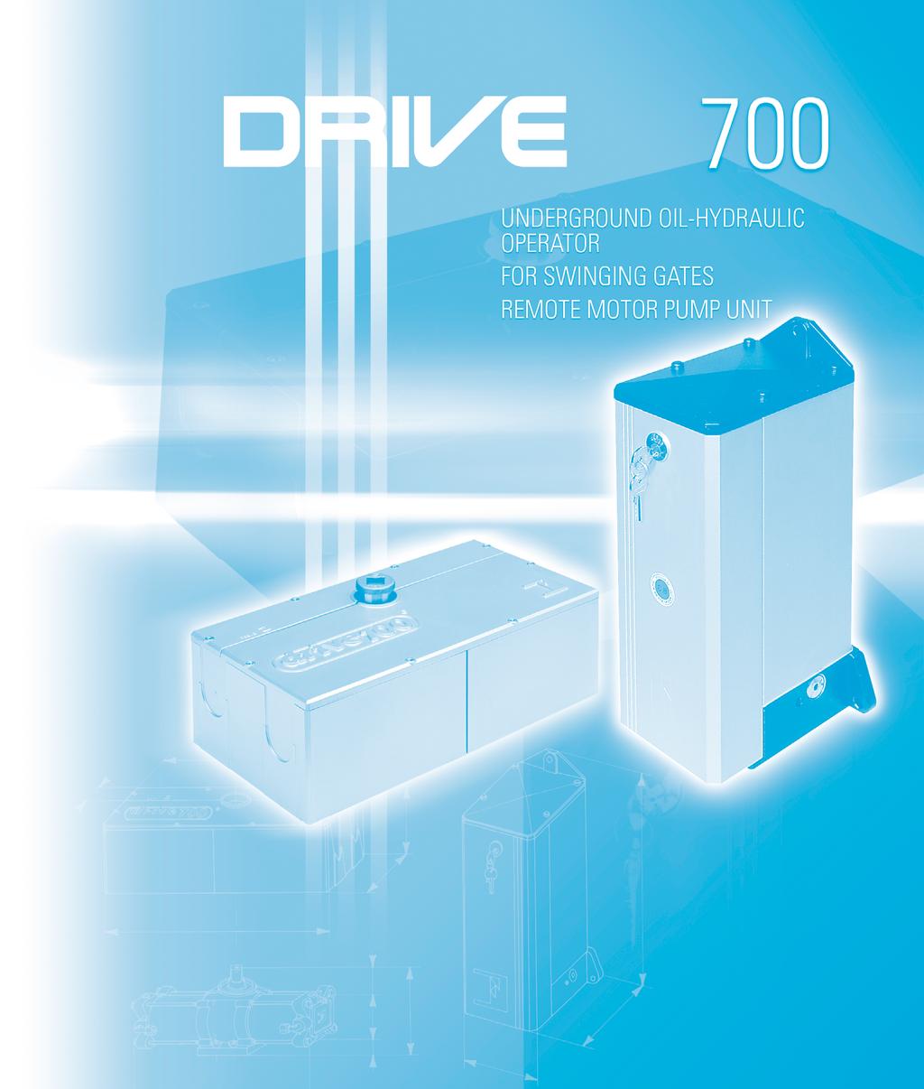
DRIVE 700 OVERALL DIMENSIONS
|
|
|
- Sara Bailey
- 5 years ago
- Views:
Transcription
1 GB INSTALLATION MANUAL
2 DRIVE 700 INSTRUCTIONS TO INSTALL THE SYSTEM FOR A PERFECT APPLICATION AND PERFORMANCE OF DRIVE 700 SYSTEM IT IS RECOMMENDED TO KEEP TO THE INSTRUCTIONS AND THE DIAGRAMS IN THIS MANUAL. IMPORTANT:THE INSTALLATION IS TO BE CARRIED OUT BY QUALIFIED TECHNICAL PEOPLE IN COMPLIANCE WITH EN EN SAFETY NORMS AND 98/37/EC MACHINE DIRECTIVE. GENERAL FEATURES DRIVE 700 is an electro-hydraulic mechanism, part of which to be fitted under the ground while the motor pump unit is external and separately fitted, to operate single or double swinging gates. Recommended gate weight is 700 kg per gate. The two basic versions allow rotation angles of 110 and 175 degrees respectively. Both versions are also available in different options, as follows: non locking (an electric lock is recommended to be fitted to the gate/s); locking where the gates are hydraulicaly locked in any required position by DRIVE 700 in either directions of movement ie. opening or closing; Braking on Opening and Closing, non Braking; and eventually they can be fitted with a flow regulator to control and keep constant the speed of the gates during the rotation movements. IMPORTANT: All the above models of DRIVE 700 imply that the gates are fitted with an electric lock in case they are wider than 2 meters. PRELIMINARY INSPECTION OF THE GATE CONDITION Before going on fitting DRIVE 700 it is recommended to carry out the following: - Make sure that the gate structure is adequate to be electrically operated: check that all the metallic parts, if any, are all right and do not show deformation, strengthen possible weak points and inspect the hinges to be in perfect good condition without any friction points etc. - No obstacle is to interfere with the gate travel: make sure that the ground in the area of the gate movement is levelled. - The gates are to be well built, mounted straight and aligned. - IMPORTANT: Gate stops are to be provided and firmly fixed in the required open and closed gate positions. Verify solidity before operating the system. GATE POST WALL SWINGING GATE TO OPERATE MOTOR PUMP UNIT FIXING MOTOR PUMP FRONT COVER F-RING SQUARE SECTION HOLE GATE STOP IN CLOSED GATE POSITION LATCH TO HOLD GATE IN CLOSED POSITION ENCLOSURE LID. NERROW SECTION OIL-HYDRAULIC JACK ENCLOSURE GATE STOP IN OPEN GATE POSITION PIC. 1 ENCLOSURE LID. LARGE SECTION GUIDE BASE FIXING ANGLES 2
3 PREPARING THE GATE The gate to be operated must be prepared to take the DRIVE 700 mechanism. For a perfect performance of the system, it is most important that the gate is hanged only by the top hinge whereas the mechanism rotation shaft is to provide a seat for the gate and replaces the lower hinge (Pic. 2). 65 mm IMPORTANT: Ideally the gate hinge centre line should be approximately 65 mm away from the gate post surface line (Pic.2) With existing gates, it is sufficiente that the DRIVE 700 jack, ie. the underground mechanism, is positioned closed to the gate post in axis with the centre line of the gate top hinge. NOTE: With existing gates, remove the lower hing and fit the shaft ring in compliance with the indications provided on page 4, Putting the jacks in phase. PIC. 2 FITTING THE JACK - Dig a hole in the ground at the gate foot, close to the gate post, as indicated in Pic. 3. IMPORTANT: The dimensions indicated are in consideration that the hole has to be large enough to accomodate the jack, to fit the two halves of the enclosure around it, and the piping between the jack and the external motor pump unit (read the section installation of the motor pump on page 5). - Set the fixing base plate with concrete at the bottom of the hole ie. 130 mm deep from ground level. Make sure that it is perfectly straight and levelled as it is to take the hydraulic jack on to it and ensure that the shaft center and the top hinge center are aligned on the same axis. - Let the concrete set well around the fixing base plate so this can provide a firm setting to further operations (Pic.3). GATE 65 mm SPIRIT LEVEL TOP HINGE GATE POST SPIRIT LEVEL GATE POST 550 mm 280 mm 220 mm GATE 65 mm 280 mm GATE POST ESCAVATE UNDER THE GATE FOOT CLOSE TO THE GATE POST 220 mm 130 mm CONCRETE SETTING 20 mm PIC. 3 3
4 - Lay the jack, which is fitted with a guide base plate, on to the ground fixing base plate. - Make sure that the jack, once fitted on to the base plate fixed to the ground, has the shaft straight with the top hinge center line: a plumb line is recommended in this case to ensure that the jack shaft is in true vertical position (Pic.4). - Weld the four angles, provided with the equipment, on to the ground fixing base plate to match the position of the corners of the jack base plate, to keep the jack in the correct position (Pic.5). NOTE: Before fixing the corners, operate the gate manually open and closed to assess smoothness and alignment. JACK PIC. 4 ANGLES ROTATION SHAFT IN AXIS WITH THE HINGE CENTER LINE PIC. 5 GUIDE BASE ANGLES WELDED ON TO FIXING BASE PUTTING THE JACKS IN PHASE The oil-hydraulic jack is to be fitted to the gate by means of a specially designed ferrule (f-ring) having a square center hole. A reinforcement plate is generally recommeded to fix the F-ring to the gate foot. Before this operation, it is needed to put the jacks in phase: that is to say to set the jack shaft in the required position to achieve correct gate operation by rotating the shaft to the limit of the permitted stroke in closed gate position; this is to be done before welding the angles on to the fixing base plate and before piping the jack to the motor pump unit. PLEASE NOTE: It is extremely important that the jack shafts are in the correct phase to ensure that the gates are properly and securely driven to close position and the setting is maintained for long time. - By means of a wrench rotate the jack shaft until you can feel that the limit of the permitted stroke in closed gate position is reached: in this position it can be noted that one of the flattened sides of the shaft is now positioned 5 degrees beyond the closed gate line (no need to rotate hard, as the jack is not piped yet and no fluid is inside it yet). JACK FIXED TO THE GATE STOP IN CLOSED POSITION JACK FIXED TO THE 5 5 PIC. 6 4 CLOSED GATE CLOSED GATE
5 - Make sure that the hydraulic jack is perfectly levelled before fixing the F-ring by tightening or loosening the adjusting screws in the jack guide base (Pic.7). A spirit level can be used to assess levelling. - Fit the F-ring to the jack shaft and indelibly mark it so that the required shaft fitting position can be noted on it (this is quite simple as both the shaft and the F-ring have four flattened faces). - Remove the F-ring from the shaft (Pic.8) - Rotate the shaft back by a wrench so that the nearest flattened face is aligned with the gate in closed position. - Fit the F-ring back to the shaft in the same position as marked before. - Before definitely fixing the parts, spot weld the F-ring to the plate and the plate to the gate and carry out some maual open and close operations of the gate. SPIRIT LEVEL ADJUSTING SCREWS SPIRIT LEVEL PIC. 7 ROTATION SHAFT DRIVE 700 F-RING ROTATE TO THE LIMIT OF THE PERMITTED CLOSE END STROKE F-RING ROTATE THE SHAFT UNTIL THE FLATTENED SIDE IS STRAIGHT WITH THE GATE IN CLOSED POSITION STRENGTHENING 5 CLOSED GATE AXIS CLOSED GATE AXIS PIC. 8 - Weld the F-ring to the gate foot and interpose a strengthening plate between them, making sure that the parts are vertically straight with the gate top hinge center line and that the fixing geometry has been strictly respected as indicated before. Perfect alignment of the DRIVE 700 shaft with the gate hinge is essential to the correct operation of the gates (Pic.9). FITTING THE MOTOR PUMP UNIT The hydraulic motor pump unit is to be fitted at a suitable distance from the jack so as piping can be as easy as possible in respect of the site requirements. It is also to be considered that an easy access to the internal parts of the hydraulic motor pump unit is recommended during the fitting operations and to be able to override the system for manual operations in events like an emergency or power failure. PLEASE NOTE: for gates wider than 2 meters it is always recommended to use the non locking version of the motor pump unit and fit the gates with an electric lock - Before starting the piping operations, bring the enclosure apart. Drill a hole in the lateral component, where piping is required, the size of the hole must be adequate to take a tube through it, into which the pipes from the motor pump unit to the jack are to be laid (Pic.10 and 12). ENCLOSURE WELD THE F-RING TO THE STRENGTHENING AND THIS TO THE GATE TUBE TO HOUSE THE PIPES PIC. 9 LATERAL ENCLOSURE COMPONENT PIC. 10 5
6 - Fix the electro-hydraulic motor pump unit by means of expanding bolts (not included). It is to be fixed close to the gate to operate in the most suitable position considering all the fitting, setting and testing operations involved. - Excavate between the jack and the motor pump (Pic.12) and lay a tube to house the pipes: copper pipes are supplied on request in one length to be bent on site to meet the application requirements. FIXING BOLTS HYDRAULIC MOTOR PUMP UNIT HYDRAULIC JACK PIC. 11 HYDRAULIC MOTOR PUMP UNIT KEY HYDRAULIC JACK HYDRAULIC MOTOR PUMP UNIT PIPES FRONT COVER SPIGOT GRAVEL LAYER TO PROVIDE A SOAKAWAY OIL-HYDRAULIC JACK ENCLOSURE PIPE CONDUIT NUT 3 mm ELBOW FITTING PIC. 12 IMPORTANT: Avoid sharp bending in the pipes between the motor pump unit and the jack; make sure that all nuts in the jack and motor pump are well tightened. - Assemble the enclosure around the jack and fix it with concrete. Fill in the whole escavation from the hole where the jack is located to the motor pump unit where the pipes are laid. FILLING THE MOTOR PUMP WITH POWER OIL - Unlock the motor pump front cover by the provided key and remove it. Incorporated in the motor pump unit is a funnel. Pull it outwards (2 cm approx.) and turn it up (Pic. 13). - The power oil, supplied with the equipment in a 3 l container, is to be poured up to the sight glass. POWER SUPPLY CABLE FUNNEL OIL LEVEL SIGHT GLASS 6 PIC. 13
7 FITTING THE ELECTRIC LOCK, THE MECHANICAL LATCHING BOLT AND THE GATE STOPS It is recommended to fit the gates with an electric lock either vertically or horizontally positioned (70 cm high from ground level in the second case) in order to better hold the gates in the closed position. The gate that is fitted with the electric lock is to be 5 degrees out of phase against the other one and has to reach the stop closed position a bit later than the gate that is fitted with the catching plate. In the case where the gate lock is horizontally fitted, it is also needed to fit a latching bolt to the gate that first reaches the gate stop. The bolt is latched into the gate stop by the other ie. the delayed gate on approaching the gate stop (Pic.14). IMPORTANT: Provide the installation with gate stops in the open gate position to be fixed 5 before the jack reaches the very end of the permitted stroke. DELAYED GATE HORIZONTAL ELECTRIC LOCK THIS GATE CLOSES FIRST HORIZONTAL ELECTRIC LOCK CATCHING IIN CLOSED POSITION 70 cm LATCHING BOLT 90 GATE STOP OPEN POSITION THIS GATE CLOSES FIRST GATE STOP CLOSED POSITION 95 VERTICAL ELECTRIC LOCK 70 cm FIT THE HEAD OF THE GATE THAT CLOSES FIRST WITH A LATCHING BOLT TO BE DRIVEN INTO THE CLOSED POSITION GATE STOP WHERE A HOLE HAS BEEN PROVIDED FIRST PIC. 14 ELECTRICAL CONNECTIONS TO ELPRO 13 CEI CONTROL PANEL Before carrying out any electrical connections read the enclosed electrical wiring diagrams (Pic.15). IMPORTANT: All the equipment must be properly earthed (Pic.15). - The mains, electric motor and flashing lamp wires must have a 1.5 mm 2 square section for a max. distance of 50 m in case that a longer distance is required, section must be 2 mm mm 2 square section wires can be used for the accessories such as the photocells, keyswitch etc. 1) MIRI 4 FLASHING LAMP 2) ELPRO 13 CEI CONTROL PANEL 3) O.O3 A MAGNETIC-THERMAL CIRCUIT BREAKER 4) JUNCTION BOX 5) DRIVE 700 MOTOR PUMP UNIT 6) DRIVE 700 JACK 7) POLO 44 PHOTOCELL RECEIVER 8) ELECTRIC LOCK 9) POST-MOUNTED POLO 44 PHOTOCELL PROJECTOR 10)POST-MOUNTED POLO 44 PHOTOCELL RECEIVER 11)POLO 44 PHOTOCELL PROJECTOR 12) JUBI 433 EXTERNAL RADIO RECEIVER 13) BIRIO A 8 AERIAL 14) PRIT 19 KEYSWITCH ) JUBI 433 TRANSMITTER RG58 cable n 4x1 n 2x1 n 4x1 n 2x1.5 n 4x V 50 Hz n 4x1 n 4x1.5 n 4x n 2x1 8 GATE STOP IN CLOSED GATE POSITION GATE STOP IN OPEN GATE POSITION AT GATE STOP IN OPEN GATE POSITION AT n 4x1 9 PIC. 15 n 2x1 15 7
8 - Carry out all the electrical connections to the Elpro 13 CEI control panel - First running test: set the Motor Run Time 09 to a value 4-5 seconds higher than the time required by the gates to reach the gate stop; set the Dwell Time 08 (automatic mode) and Gate Delay Time in Closing Cycle 07 (in case of double swinging gates) as required, pic. 16: - Automatic Mode: Dip-switch B No. 3 set to ON. Once an open pulse is given (to terminals 4 and 8 in Elpro 13 CEI main terminal board, pic.16), the gates are driven to open, stopped for a time as set by the Dwell Time 08 and then automatically re-cycled to close. - Semi-automatic Mode: Dip-switch B No. 3 set to OFF. Once an open pulse is given, the gates are automatically operated only to open; a second pulse (to terminals 5 and 8 in the Elpro 13 CEI main terminal board, pic.16) is needed to close the gates. - Radio Contact: terminals 7 and 8 in the Elpro 13 CEI main terminal board, pic.16. Any pulse from a keyswitch, remote control or push button reverses the gate travel (it is recommended to carefully read the instructions provided in the control box). FOR SWING GATES SINGLE-PHASE B TERMINALS FOR THE CONNECTION OF THE PUSH BUTTONS PULIN 3 ON Should more pairs of photocells be required than the recommended quantity, fit an auxiliary transformer outside the control box. DIP-SWITCH 3 4 RADIO CONTROL PLUG-IN CARD SUPPORT ON 1 CHANNEL 24 V OUTPUT PEDESTRIAN MODE ONE PULSE OPENS ONE GATE LEAF ONLY MICROPROCESSOR FADINI OFF -PHOTOCELLS 2nd PAIR- INSIDE PHOTOCELLS N.C. contact. If obstructed, they prevent the gates from opening, reverse gate direction during close cycle. ON TO 0 THE DELAY IS OUT OF SERVICE N.C. CONTACT. PHOTOCELLS COMMON OPEN SWITCH N.O. CONTACT CLOSE SWITCH N.O. CONTACT STOP SWITCH N.C. CONTACT RADIO CONTACT N.O. 7 8 COMMON VOLTAGE OUTPUT ELECTRIC LOCK SUPPLY 0 24 V - 3 W max. INDICATOR Max. permitted load: 24 Vac OUTPUT 2 pairs photocells 1 radio receiver LEAF DELAY TIMER + CLOSE + DWELL TIME MOTOR RUN + TIME OPEN & CLOSE COMMON CAPACITORS 12,5 µf 12,5 µf M1 COMMON F5 M2 ELECTRIC MOTORS SINGLE-PHASE 1 FUSE: 24 V OUTPUT TERMINALS V - 25 W max FLASHING LAMP CUT OFF SWITCH BY COVER KNOB 230 V SINGLE-PHASE SUPPLY VOLTAGE F3 F4 630 ma FUSE F2 5 FUSE F1 630 ma 5 FUSE FUSE FLASHING LAMP N. W.: for special applications, ie. to switch on lights - CCTV etc, SOLID STATE RELAYS are recommended to be used only. Standard relays would affect the micro-processor. N.W.: THIS PANEL IS TESTED TO OPERATE GATES ONLY THROUGH FADINI ACCESSORIES. NO GUARANTEE FOR ACCESSORIES OF OTHER MAKE OR SPECIAL APPLICATIONS. PULSE TWICE CONSECUTIVELY TO OPEN BOTH GATE LEAFS ALL OPERATIONS OPEN, CLOSE & REVERSE RADIO CONTACT Drwg PIC. 16 8
9 FEATURES OF THE ELECTRONIC PROGRAMMER FOR SWINGING GATES All the electrical connections are to be made as per the following instructions and diagrams. Supply the terminals with 230V - 50 Hz single phase voltage. The red LED switches on and stays on as long as the board is properly supplied. Through the timer No. 9 you can control the running time of the motor in both cycles, OPEN and CLOSE. Set it so that the running time of the motor is longer than the actual travel of the gate: set the timer No. 8 -DWELL- ie. the interval between open and re-closing, so that you can meet the required interval of time. - With the electric motor connected to terminals : the delay is operative in the open cycle, with a factory pre-set time. - With the electric motor connected to terminals : the delay is operative in close cycle and can be adjusted through the timer No. 7 on to less or more. LOGIC OF THE ELECTRONIC PROGRAMMER: When a pulse is given, the flashing light switches on. After three seconds the motors start. During the interval before re-closing, the light stays on. When the gates are fully re-closed, the light keeps on flashing for three more seconds and then switches off automatically. The 3 second interval (pre-flashing) which precedes the actual start of the motors can be eliminated by means of the DIP-SWITCH B No.4. LED No. 1: It switches on when voltage is supplied. LED No. 2: PHOTOCELLS. Normally on. It switches off when the photocells are obstructed. LED No. 3: OPEN. It switches on when the respective switch is activated. LED No. 4: CLOSE. It switches on when the respective switch is activated. LED No. 5: STOP. Normally on. It switches off when the respective switch is activated. LED No. 6: RADIO. It switches on whenever a pulse is given, either from remote control, keyswitch or push buttons. DIP-SWITCH B SETTING IN ELPRO 13 CEI N 1 OFF = PHOTOCELLS. NO STOP IN OPEN CYCLE. REVERSE/CLOSE N 2 OFF = REMOTE CONTROL. REVERSE N 3 OFF = NO AUTOMATIC RECLOSING N 4 OFF = NO PRE-FLASHING N 5 OFF = REMOTE CONTROL. NO STOP AND HOLD AS LONG AS BUTTON DOWN. IT OPENS STRAIGHT AWAY N 6 OFF = BOTH LEAFS ARE OPERATED N 7 OFF = STROKE REVERSING PULSE OUT OF SERVICE N 8 OFF = LEAF DELAY OPEN CYCLE. ONE STARTS BEFORE THE OTHER N 1 ON = STOP DURING OPEN CYCLE N 2 ON = NO REVERSE DURING OPEN CYCLE N 3 ON = AUTOMATIC RECLOSING N 4 ON = PRE-FLASHING N 5 ON = STOP AND HOLD AS LONG AS THE BUTTON IS KEPT DOWN N 6 ON = PEDESTRIAN. ONE LEAF ONLY GATES IN CLOSED POSITION N 7 ON = S. R. P. IN SERVICE GATES IN CLOSED POSITION N 8 ON = NO LEAF DELAY BOTH MOTORS START TOGETHER LAMP ON = GATE OPEN LAMP FLASHES SLOWLY = GATE OPENING LAMP FLASHES FAST = GATE CLOSING LAMP OFF = GATE CLOSED 1) It is advisable not to expose the control box directly to weather conditions; if mounted outside, a suitable enclosure is recommended to protect it from sunshine and rain. 2) Bridge terminals 1-2 if you do not require any photocells. 3) Should two sets of photocells be required, these are to be series connected to terminals 1-2, contact normally closed. 4) Bridge terminals 6-8 if you do not require any keyswitch or push buttons. 5) Fit the mains to the control box with a high sensitivity, differential, magnetic-thermal switch, 0.03 Amps. 6) OPERATING MODE WITH TWO PAIRS OF PHOTOCELLS, INDEPENDENT FROM EACH OTHER Dip-switch No. 1 set to OFF, connect the pair of photocells that are inside the property to the terminals marked 2nd pair. The second pair always stops the gate in open cycle in case of an obstacle. During close cycle the second pair reverses the gate direction. 7) NOTE WELL FAULT FINDING: - Check supply voltage with a tester: it must be 230 V, single-phase. - Check the high voltage fuses. - Check the low voltage fuses. - Check if the photocell contacts are normally closed. - Check voltage from the control box to the electric motor(s): power might have dropped. - The section of the electric cables to the motor(s) must not be less than 1.5 mm 2. - Connect the other pair to the terminals 1-2 This pair performs in the standard pre-set mode, ie: no stop during open cycle, REVERSING GATE DIRECTION DURING CLOSE CYCLE. Terminals to stay linked out should the second pair of photocells not be used, and set the desired operating mode through Dip-switch No. 1. * 24 V ~ output. Terminals It can supply power for 2 pairs of photocells plus 1 radio receiver. Terminal 11 provides a power output for a lamp. 24 V - 3 Wmax. Flashing lamp output. Terminals Maximun available power 25 Wmax. 9
10 FEATURES AND TECHNICAL SPECIFICATIONS Elpro 13 CEI represents the latest state of the art technology for control panels. It is extremely versatile and can meet the most various requirements. It is fitted with the Cut Off Switch by cover knob. It has the same functions as Elpro 9 and incorporates additional advantages as follows: Stroke Reversing Pulse, Pedestrian Operating Mode (where one leaf only can be operated allowing people to walk in/out), STOP and HOLD function by keeping the remote control button pressed down. Further improvements can be noted in the Elpro 13 CEI : - Addition of a 1 Amp. fuse to the 24 V circuit as a protection for the accessories (remote control - photocells -etc.) which are connected to the terminals and for the panei itself in that it can prevent short circuit during installation. - The pulse to the electric lock is increased to 2 seconds. Releasing is so much easier as the electric lock is released with an anticipation of 100 msec. before the gate starts moving. - A 24 V - 3 W lamp indicates gate operations (Gate CLOSED = Lamp OFF - Gate in OPEN cycle = Lamp flashes slowly - Gate OPEN = Lamp stays ON without flashing - Gate in CLOSED cycle = Lamp flashes fast). - It provides a better switching intelligence design to enhance the reliability of the relays. - The Motor Run Time is independent from the Leaf Delay Time in close cycle (the delay time is automatically added to the duration of the opening time). - The 8 Dip-switches can be arranged into any of the possible patterns to achieve the required operating modes without any risk of interference with one another. STROKE REVERSING PULSE and S.1A.P. Set Dip-switch No.7 to ON. The Stroke Reversing Pulse (S.R.P.) is activated only with the gate in the closed position. The pulse operates the gate in the CLOSED direction first and then immediately reverses into OPEN (This will help the gate lock to release). All the other operations will be performed in the standard way. No danger comes from the Stroke Reversing Pulse. This function remains in service with the panel set to Pedestrian Mode. Set Dip-switch No.6 to ON for Pedestrian Mode (S.1A.P.), terminals 3-4. Only one leaf is operated when the OPEN button is pressed down. Automatic reclosing. If the OPEN button is pressed twice in a row, both leafs are opened. The S.1A.P. function is activated only when the gate is in the fully CLOSED position. The remote control always operates both gates, terminals 7-8. FIRST RUNNING TEST Once satisfied that the electrical connections have been completed as described, test the system to make sure that it works as required: it is essential that on pulsing to the electric motors of the oilhydraulic motor pump units both gates are to be operated in the same direction. Should they fail to perform in a synchronized way, swap the electrical motor connections, ie. live 1 and 2 for both gates to open (Pic.17). PLEASE NOTE: should the electric motors fail to start because of electric power shortage, fit a 12.5 µf capacitor between the two live wires (Pic. 17) 12,5 µf VOLTAGE SUPPLY CABLE COMMON LIVE 1 LIVE 2 ADDITIONAL CAPACITOR PIC. 17 PRESSURE ADJUSTMENT Remove the oil-hydraulic motor pump unit front cover; the two pressure valve adjustment screws can be noted in the base of the unit, one is red in colour and controls pressure in the close cycle (check the electric motor connections), the other one is green for the open cycle (Pic.18). A screwdriver is needed to adjust the valve pressure: the tighter the screw is driven the higher the pressure is; by turning it the other way round, pressure is decreased. ADJUSTING VALVE SCREWS CLOCKWISE = MORE POWER ANTI-CLOCKWISE = LESS POWER PIC
11 OVERRIDING AND MANUAL OPERATION In cases when power fails and during some phases of installation, it is needed to override the system and operate the gates by hand, DRIVE 700 operators, locking version, still fitted to the gates: remove the front cover of the oil-hydraulic motor pump unit and unscrew the release knob by one or max. two turns. The knob is fitted in the base of the unit (a key is supplied with the equipment to unlock the front cover (Pic.19). IMPORTANT: If DRIVE 700 non locking version has been fitted, and manual operation is required, unlock the gate electric lock by means of its key, and open the gate. No need to do any operation with the DRIVE 700 system. RELEASE BY 1 OR 2 TURNS TO OVERRIDE DRIVE 700 LOCKING FOR MANUAL OPERATIONS RELEASE KNOB PIC. 19 BRAKE ADJUSTMENT ie. DAMPENING Should a DRIVE 700 system braking in Open and Close cycles have been installed, it is necessary to adjust the brake ie. the dampening device to slow down speed over the last 40 cm of the gate travel, before the gates reach the gate stop (please remember, it is essential that the installation is fitted with gate stops in the open and closed gate positions). Pic 20: - Remove the two parts of the enclosure lid - The screw that controls the dampening device is fitted in the end cap of the oil-hydraulic jack: tighten the screw to increase the slowing down effect, loosen it to increase speed on approaching end of travel. BRAKE ADJUSTMENT SCREW PIC. 20 AIR BLEEDING This operation is needed after completing and testing the installation. A screw is fitted in the jack end cap for air bleeding. Loosen the screw for a little while. At the beginning some air and oil can be noted to come out. When only oil comes out, firmly tighten the screw. Avoid overtightening (Pic. 21). BRAKE ADJUSTMENT SCREW AIR BLEED PIC
12 110 DRIVE 700 OVERALL DIMENSIONS TECHNICAL SPECIFICATIONS ELECTRIC MOTOR Power Yield KW (0.33HP) Supply voltage...230v Frequency...50Hz Absorbed current...2a Absorbed power W Capacitor µf Motor rotation speed r.p.m. Intermittent service... S3 OIL-HYDRAULIC MOTOR/PUMP UNIT Pump flow rate P l/1 min. Average working pressure...1mpa (10bars) Max. pump pressure...3mpa (30bars) Oil type...oil FADINI A 15 BY AGIP Tank capacity dm 3 Static weight...8 Kg Working temperature C C Protection standards...ip 673 OIL-HYDRAULIC JACK Rotation angle /175 Rotation time s Rotation time s Max. rated torque...235nm Piston diametre...75mm Piston stroke...52mm Working temperature C C Oil volume...0,25dm 3 Static gate weight...700kg PERFORMANCE Duty cycle:...23 s Opening - 30 s Dwell - 23 s Closing Time of one complete cycle:...76s No. of complete cycles Opening-Stop-Closing...47/Hour cycles per year, 8 hours service per day CHECKING AND MAINTENANCE: To achieve an optimum performance and longer life of the equipment and in observance of the safety regulations, it is recommended that inspections and proper maintenance are made by qualified technicians to the whole installation ie, both the mechanical and electronic parts, as well as wiring: - Mechanical parts: maintenance every 6 months approx. - Eletronic apparatus and safety equipment: maintenance every month. The growth of MECCANICA FADINI has always been based on the development of guaranteed products thanks to our TOTAL QUALITY CONTROL system which ensures constant quality standards, updated knowledge of the European Standards and compliance with their requirements, in view of an ever increasing process of improvement. EUROPEAN MARK CERTIFYING CONFORMITY TO THE ESSENTIAL REQUIREMENTS OF THE STANDARDS 98/37/EC DECLARATION OF CONFORMITY GENERAL WARNINGS EN 12453, EN STANDARDS CEI EN STANDARDS WARRANTY CERTIFICATE AUTOMATIC GATE MANUFACTURERS s.n.c. Made in Italy Distributor s box The manufacturers reserve the right to change the products without any previous notice and are not liable for possible damages to people and properties. Via Mantova, 177/A Cerea (Verona) Italy - Tel r.a. - Fax info@fadini.net -
TECHNICAL DATA HYDRAULIC UNIT
 GB INSTRUCTIONS MANUAL RISING BOLLARD OIL-HYDRAULIC AUTOMATION COMPONENTS strabuc 918 RELEASE KEY PLUG FOR RELEASE HOLE BOLLARD COVER 12 V WARNING LIGHTS REFLECTORS COMPLETELY RETRACTABLE POST WITH ELECTROPHORESIS
Oil-hydraulic operator for swinging gates
 COMBI 740 Oil-hydraulic operator for swinging gates Below ground Version with two-way locking device Version with brake in open/close cycles Version with 110 and 175 shaft rotation Instruction manual GB
INSPECTIONS AND MAINTENANCE
 GB INSTRUCTIONS MANUAL STRABUC 930 ARMOURED OIL-HYDRAULIC RISING BOLLARD COMPONENTS strabuc 930 RELEASE KEY PROTECTION PLUG TO ACCESS RELEASE HOLE BOLLARD COVER 12V WARNING LIGHTS REFLECTORS RISING POST
BAYT 980. Oil-hydraulic OIL-HYDRAULIC BARRIER FOR TRAFFIC CONTROL INSTALLATION MANUAL. code 4425 Post with fixing base. POLO 44 - optional -
 Oleodinamica BAYT 980 Oil-hydraulic OIL-HYDRAULIC BARRIER FOR TRAFFIC CONTROL POLO 44 - optional - BAYT 980 560 code 4425 Post with fixing base the gate opener Made in Italy INSTALLATION MANUAL GB INSTRUCTIONS
INSTALLATION MANUAL GB
 GB INSTALLATION MANUAL @GB; 66 FITTING INSTRUCTIONS Important: Keep to the instructions outlined in the pages and diagrams that follow to achieve a perfect installation. NUPI 66 is an oil-hydraulic actuator
CHECKING AND MAINTENANCE:
 GB INSTALLATION MANUAL APROLI 480 OIL-HYDRAULIC OPERATOR FOR GARAGE DOORS SECTION VIEW OF THE OIL-HYDRAULIC OPERATOR WITH LAMP AND COVER UPPER SECTION SUPPORT LAMP REFLECTOR LIGHT DIFFUSION COVER 230 V-25
NYOTA 115. Electro-mechanical sliding gate operator. Instruction manual
 NYOTA 115 Electro-mechanical sliding gate operator Instruction manual GB INSTRUCTIONS FOR THE INSTALLATION OF THE AUTOMATION NYOTA 115 FOR A CORRECT INSTALLATION AND GOOD PERFORMANCE OF NYOTA 115 READ
Instructions manual. Below ground oil-hydraulic operator for swinging gates. pages 17-32
 Below ground oil-hydraulic operator for swinging gates STANDARD VERSION: 110 or 17 Leaf Rotation Compact, internal drive unit and hydraulic jack Normal version or version with two-way Locking device Models
GB INSTALLATION MANUAL
 GB INSTALLATION MANUAL MEC 800 SPECIAL OIL-HYDRAULIC OPERATOR FOR SWINGING GATES. EXTERNAL APPLICATION. ESSENTIAL COMPONENTS TO FIT THE OPERATOR TO A GATE LEAF FIXING BOLT FLEXIBLE TUBE 0.5 meter STRAIGHT
GB Instructions Manual
 GB Instructions Manual pages - 8 CMYK- 0 0 KYMC- 0 0 KYMC- 0 0 0 KYMC- 8 KYMC- 0 KYMC- 0 0 0 KYMC- 0 0 0 0 Underground oil-hydraulic operator for swinging gates or 7 shaft rotation Compact all-in-one oil-hydraulic
EC MACHINE DIRECTIVE COMPLIANCE DECLARATION
 EC MACHINE DIRECTIVE COMPLIANCE DECLARATION (DIRECTIVE 89/392 EEC, APPENDIX II, PART B) Manufacturer: FAAC S.p.A. Address: Via Benini, 1 40069 - Zola Predosa BOLOGNA - ITALY Hereby declares that: the 770
BAYT 980. Oil-hydraulic Road Traffic Barrier. BAYT 980 painted version BAYT 980 stainless steel version inox
 BAYT 980 Oil-hydraulic Road Traffic Barrier BAYT 980 painted version BAYT 980 stainless steel version inox GB Oil-hydraulic road traffic barrier BAYT 980 The Bayt 980 operator is a road barrier used to
D Vers. 03 ELECTROMECHANICAL AUTOMATION FOR SWING GATES
 E5 D811007 15-09-99 Vers. 03 ELECTROMECHANICAL AUTOMATION FOR SWING GATES 122 This product complies with recognised technical standards and safety regulations. We declare that this product is in conformity
1-24. Oil-hydraulic. Oil-hydraulic road barrier for traffic control from 3 to 8 metres
 GB Instructions manual pages 1-24 Oil-hydraulic Oil-hydraulic road barrier for traffic control from 3 to 8 metres Stainless steel and painted versions Version with aluminium fence Version with articulated
I - Libretto di istruzioni GB - Instructions manual F - Notices de montage
 I - Libretto di istruzioni GB - Instructions manual F - Notices de montage GB Instructions manual pages 1-20 BOLLARD WITH RETRACTABLE CYLINDRICAL POST OIL-HYDRAULICALLY OPERATED the gate opener made in
EC MACHINE DIRECTIVE COMPLIANCE DECLARATION
 770 EC MACHINE DIRECTIVE COMPLIANCE DECLARATION (DIRECTIVE 89/392 EEC, APPENDIX II, PART B) Manufacturer: FAAC S.p.A. Address: Via Benini, 1 40069 - Zola Predosa BOLOGNA - ITALY Hereby declares that: the
Contents. EC DECLARATION OF CONFORMITY FOR MACHINES... p. 10. WARNINGS FOR THE INSTALLER... p. 10
 Contents EC DECLARATION OF CONFORMITY FOR MACHINES... p. 10 WARNINGS FOR THE INSTALLER... p. 10 1. DESCRIPTION AND TECHNICAL SPECIFICATIONS... p. 11 1.1. DIMENSIONS... p. 11 2. ELECTRIC DEVICES (standard
Typical Installation Schematic
 The 760 Gate Automation System The FAAC 760 automation system consists of a monoblock hydraulic unit and foundation box assembly. The system is designed for underground installation, and will not alter
DKC400Y AC Sliding Gate Installation Manual. Sliding Gate Opener. Model: DKC400Y. Installation Manual WARNING
 Sliding Gate Opener Model: DKC400Y Installation Manual WARNING Read and thoroughly understand all instructions before installing or operating this automatic gate opener. Failure to do so may cause serious
Automation Swing Gate Opener
 Automation Swing Gate Opener Operating and installation instructions SP EIFFEL 400 V1.0 Rev 08/01 CONTENTS 0) GENERAL SAFETY REGULATIONS...Page 0 1) DESCRIPTION...Page 03 ) TECHNICAL SPECIFICATIONS 3)
PW320/PW330 USER MANUAL SWING GATE OPENERS 24V DC GEAR MOTOR FOR RESIDENTIAL. Flashing Light. Push Button. Control box. Gate 2.
 PW320/PW330 USER MANUAL SWING GATE OPENERS 24V DC GEAR MOTOR FOR RESIDENTIAL Flashing Light Push Button Control box Gate 2 Gate 1 Declaration of Conformity Applicant: Powertech Electronics Inc. Manufacturer:
Instruction Manual for the. E-SL 450 Series
 Instruction Manual for the E-SL 450 Series Estate Slide Summary of Functions The Estate Slide is only to be used for vehicular Slide gates in a Class I setting. Class I: A vehicular gate opener (or system)
Automatic concealed bollards 275 H600 and 275 H800 with pit
 Automatic concealed bollards 275 H600 and 275 H800 with pit Technical installation manual CE Declaration of conformity Warnings for the installer Bollard technical data Preparing and installing the bollard
PW150/PW200 USER MANUAL SWING GATE OPENERS 24V DC GEAR MOTOR
 PW150/PW200 USER MANUAL SWING GATE OPENERS 24V DC GEAR MOTOR FOR RESIDENTIAL Flashing Light Push Button Control box Declaration of Conformity Applicant: Powertech Electronics Inc. Manufacturer: Timotion
FROG KIT. Installation Instructions for a Pair of gates... TECHNICAL HELPLINE THE FROG-P KIT CONSISTS OF:
 CAME UNITED KINGDOM LTD UNIT 3 ORCHARD PARK INDUSTRIAL ESTATE, TOWN STREET, SANDIACRE, NOTTINGHAM NG10 5BP TEL: 0115 921 0430 FAX: 0115 921 0431 TECHNICAL HELPLINE 0115 921 0430 INTERNET - www.cameuk.com
Installation Manual. Swing Gate System. Leading the way...
 Installation Manual 402 Swing Gate System Leading the way... Contents EC DECLARATION OF CONFORMITY FOR MACHINES... p. 2 WARNINGS FOR THE INSTALLER... p. 2 1. DESCRIPTION AND TECHNICAL SPECIFICATIONS...
SWING GATE OPENERS 24V DC GEAR MOTOR
 SWING GATE OPENERS 24V DC GEAR MOTOR FOR RESIDENTIAL USER MANUAL Flashing Light Push Button Control box Gate 2 Gate 1 Index 1. Warnings 2 4. Technical Characteristics 16 2. Product Description 2.1 Applications
FITTING AND CONNECTION INSTRUCTIONS
 LEPUS is an oil-bathed motor-reducer created for sliding gates automation. The motor-reducer irreversibility allows a perfect and safe gate closing avoiding the setup of an electrolock and in case of power
Sliding Gate Operator User's Manual
 Sliding Gate Operator User's Manual PY800AC/PY00AC. Products introduction Please read the instructions carefully before proceeding. MCU is supplied to control the gate operator. Keypad / single button
EC DECLARATION OF CONFORMITY FOR MACHINES (DIRECTIVE 98/37/EC) WARNINGS FOR THE INSTALLER
 WARNINGS FOR THE INSTALLER") EC DECLARATION OF CONFORMITY FOR MACHINES (DIRECTIVE 98/37/EC) Manufacturer: Address: Declares that: FAAC S.p.A. Via Benini, 1-40069 Zola Predosa BOLOGNA - ITALY 740-24V mod. operator is built to be integrated
EC DECLARATION OF CONFORMITY FOR MACHINES (DIRECTIVE 98/37/EC) Manufacturer: Address: Declares that: FAAC S.p.A. Via Benini, 1-40069 Zola Predosa BOLOGNA - ITALY 740-24V mod. operator is built to be integrated
CHECKLIST & COMPONENTS
 Eclipse Compact www.rollershuttercompany.com Tel 0800 6444121 55mm Roller Garage Doors CHECKLIST & COMPONENTS EQUIPMENT REQUIRED 2 x Step ladders or hop ups Spirit level Tape measure Power drill 10mm A/F
TEL: G&C Electronics CC E. T.
 TEL: +27 21 448 6774 G&C Electronics CC FAX: +27 21 447 7794 E. T. CK 89/31531/23 E-mail : etsystems@icon.co.za Internet: www.et.co.za 15 Nelson Road P.O. Box 34524 Observatory Groote Schuur Cape Town
SWING GATE OPENERS 24V DC GEAR MOTOR
 SWING GATE OPENERS 24V DC GEAR MOTOR FOR RESIDENTIAL USER MANUAL Flashing Light Push Button Control box Gate 2 Gate 1 Index Warnings 2 5. Technical Characteristics 21 1. Product Description and Applications
a p prove d ELECTROMECHANICAL SLIDING GATE OPENER
 EN 25 EN 25 ELETROMEHNIL SLIING GTE OPENER G The Junior gear box is built completely of die cast aluminium, and the coupling is supported by shielded roller bearings. ll of the internal operational components
INSTALLATION MANUAL (cod )
") is a bollard designed for the management of traffic areas, parkings and protection of public and private accesses. It has an hydraulic system is engineered in our factory to achieve minimum noise and maximum
is a bollard designed for the management of traffic areas, parkings and protection of public and private accesses. It has an hydraulic system is engineered in our factory to achieve minimum noise and maximum
AgriWheel Single Gate Kit Low Voltage & Solar. Installation & Operating Instructions
 AgriWheel Single Gate Kit Low Voltage & Solar Installation & Operating Instructions Thank you for purchasing you AgriWheel system. Please remove the lids from both the machine and control box and remove
BARRY BARRIER GATE AUTOMATION
 BARRY BARRIER GATE AUTOMATION Installation Manual 1. WARNINGS AND GENERAL SAFETY INSTUCTIONS This manual contains important safety information. An incorrect installation or an improper use may cause serious
Istruzioni, instructions. Motoriduttore a braccio snodato per cancelli battenti Gear motor with articulated arm for swing gates ALPHEO
 Istruzioni, instructions Motoriduttore a braccio snodato per cancelli battenti Gear motor with articulated arm for swing gates ALPHEO 1 Istruzioni, instructions Attention! This manual is for qualified
L /2012 rev 0 BISON 45 OTI UNIONE NAZIONALE COSTRUTTORI AUTOMATISMI PER CANCELLI, PORTE SERRANDE ED AFFINI
 L8542965 03/2012 rev 0 BISON 45 OTI UNIONE NAZIONALE COSTRUTTORI AUTOMATISMI PER CANCELLI, PORTE SERRANDE ED AFFINI 1 470 327 F A 500 825 B 243.5 2 C 445 210 15 ±5 205 92 50 2 3 4 I D2 D2 D1 5 T 6 D A
Automatic concealed bollards 275 H600 and 275 H800 Control station
 Automatic concealed bollards 275 H600 and 275 H800 Control station Technical installation manual CE Declaration Warnings for the installer Bollard electrical connection Technical specifications for control
Installation manual ASTER AUTOMATION FOR SWING GATES 11_16
 Installation manual ASTER AUTOMATION FOR SWING GATES 11_16 Contents 1. GENERAL SAFETY PRECAUTIONS... page 01 2. INTENDED USE AND APPLICATION... page 01 2.1 Kit contents... page 01 2.2 Technical features...
OPERATING AND MAINTENANCE MANUAL. Primary Current Injection Test Set. 750ADM-H mk2
 OPERATING AND MAINTENANCE MANUAL Product: Type: Primary Current Injection Test Set 750ADM mk2 750ADM-H mk2 DESIGNED AND MANUFACTURED BY: T & R Test Equipment Limited 15-16 Woodbridge Meadows, Guildford,
Sliding Gate Operator User's Manual
 Sliding Gate Operator User's Manual SL600AC. Products introduction Please read the instructions carefully before proceeding. MCU is supplied to control the gate operator. Keypad / single button interface.
F ERNI K I T THE FERNI-S KIT CONSISTS OF:
 CAME UNITED KINGDOM LTD ORCHARD PARK INDUSTRIAL ESTATE TOWN STREET, SANDIACRE, NOTTINGHAM, NG10 5BP TEL: 0115 921 0430 FAX: 0115 921 0431 INTERNET - www.cameuk.com E-MAIL - enquiries@cameuk.com TECHNICAL
Installation Guide Rollerdor RD55 Econ Roller Garage Door
 Installation Guide Rollerdor RD55 Econ Roller Garage Door 1 Finished door Rollerdor RD55 Econ Roller Garage Door CHECKLIST & COMPONENTS EQUIPMENT REQUIRED 2 x Step ladders or hop ups Spirit level Tape
FORCE SPD 800/1500/2000
 English AUTOMATION SYSTEMS FOR SLIDING GATES Operating and installation instructions FORCE SPD 800/1500/2000 v1.0 Rev 11/2012 INDEX 1) General Safety Regulations... pág. 01 2) Description... pág. 02 3)
ARACHNE 230V 24V- 12V
 SWING GATES OPERATOR SERIE ARACHNE 12V-24V-220V INSTRUCTIONS MANUAL SAFETY Our compliments for your excellent choice. Your new electromechanical gear motor has been produced according to a high quality
SLIDE & OL USER'S AND INSTALLER'S MANUAL V1.0 REV. 06/2017
 SLIDE & OL USER'S AND INSTALLER'S MANUAL V1.0 REV. 06/2017 00. CONTT 01. SAFETY INSTRUCTIONS INDEX 01. SAFETY INSTRUCTIONS STANDARDS TO FOLLOW 02. OPERATOR TECHNICAL SPECIFICATIONS DESCRIPTION DIMSIONS
contents Installation Maintenance DOOR OPERATOR SLIDING-1300/2100 Installation and Operating Manual DoorHan, 2012
 DOOR OPERATOR contents general information SAFETY INSTRUCTIONS operator unit Installation Electrical Connections Programming of Remote Controls Release Operation Maintenance Troubleshooting Warranty Card
TITANO 400V SLIDING GATE OPENER
 TITANO 400V SLIDING GATE OPENER USE AND MAINTENANCE MANUAL V07 /2018 TECHNICAL FEATURES א א א א QK-T3000 QK-T4000 QK-T6000 (VAC) 400 Three Phase א א א א (W) 700 750 1500 א א א א (A) 1,7 2,2 3,7 א א C -30/+70
FEATURES AND SPECIFICATIONS
 FEATURES AND SPECIFICATIONS The is a high quality hydraulic operator for residential and condominium use with leaf length up to 3 m. Available in the following versions: AC (with lock in opening and closing)
OPERATIONS MANUAL LEVER CHAIN HOIST
 OPERATIONS MANUAL LEVER CHAIN HOIST IMPORTANT SAFETY INFORMATION Please read, understand and follow all safety information contained in these instructions prior to the use of this hoist. Retain these instructions
MEKO OPENER FOR RACK-DRIVEN SLIDING MOTOR
 Installation Manual MEKO OPENER FOR RACK-DRIVEN SLIDING MOTOR 02_2016 1. WARNINGS AND GENERAL SAFETY INSTUCTIONS This manual contains important safety information. An incorrect installation or an improper
E R A I GATE AUTOMATION DIVISION
 S E R A I GATE AUTOMATION DIVISION INSTALLATION MANUAL MC/5C - 03.5C UNDERGROUND MOTOR 230 Vac FOR WING GATES UP TO 3,00m AND 300 Kg EACH WING + FOUNDATION BOX IN HOT-GALVANISED STEEL Thank you for choosing
Operating Instructions Type MPT 53
 Operating Instructions www.turnstiles.us Type MPT 53 Contents 1. Delivery... 2 2. Safety...3-4 3 Description and operation... 5 4. Technical Data 6 5. oundation...6-9 6. Assembly and installation...10-13
SKC400U SLIDING GATE OPENER OWNER S MANUAL
 SKC400U SLIDING GATE OPENER OWNER S MANUAL IMPORTANT SAFTEY INFORMATION Installing the SKC400U Gate Opener requires wiring of standard 110V electrical lines. This should only be performed by a trained
INSTRUCTIONS FOR INSTALLATION
 HYDRAULIC OPERATOR MODO 110-110/L FOR SINGLE- OR DOUBLE-WING SWING GATES INSTRUCTIONS FOR INSTALLATION GENERAL WARNINGS These warnings constitute an integral and essential part of the product and must
PROFESSIONAL 270 o PIR MOTION DETECTOR
 PROFESSIONAL 270 o PIR MOTION DETECTOR The unit can be installed only vertically (see the FIGURE 1A), not upside-down or horizontally (see the FIGURE 1B) as shown in the below drawing. FIGURE 1A 1. Motion
EC DECLARATION OF CONFORMITY FOR MACHINES (DIRECTIVE 98/37/EC)
") EC DECLARATION OF CONFORMITY FOR MACHINES (DIRECTIVE 98/37/EC) Manufacturer: Address: Declares that: FAAC S.p.A. Via Benini, 1-40069 Zola Predosa BOLOGNA - ITALY The operator mod. 844 R Reversible is built
EC DECLARATION OF CONFORMITY FOR MACHINES (DIRECTIVE 98/37/EC) Manufacturer: Address: Declares that: FAAC S.p.A. Via Benini, 1-40069 Zola Predosa BOLOGNA - ITALY The operator mod. 844 R Reversible is built
SARGON S - M - L. All rights reserved INSTALLATION MANUAL
 INSTALLATION MANUAL Our compliments for your excellent choice. SARGON LINE S (300mm) M (400mm) and L (600mm) electro-mechanical gear motor has been produced for reliability and high quality. This Manual
BISON 20 OM BISON 25 OTI
 L8542939 11/2011 rev 0 BISON 20 OM BISON 25 OTI UNIONE NAZIONALE COSTRUTTORI AUTOMATISMI PER CANCELLI, PORTE SERRANDE ED AFFINI 2 x 1,5 GND 13 8 7 5 RG 58 4 3 4 x 0,35 6 1 2 4 3 x 1,5 min 230V 2 x 0,35
V200 USER MANUAL SWING GATE OPENER. 100kg 1.5m. 100kg 1.5m
 V200 USER MANUAL SWING GATE OPENER 100kg 1.m 100kg 1.m Content Important Safety Advice... Content of the Kit... Connection Diagram... Installation Guide... Actuator... Control box... AC cable wiring...
DESIGNED FOR RESIDENTIAL APPLICATION KIT PL600/PL1000 SLIDING GATE OPENERS
 SLIDING GATE OPENER DESIGNED FOR RESIDENTIAL APPLICATION KIT PL600/PL1000 SLIDING GATE OPENERS The strongest solution for sliding gates PL600/PL1000 electro-mechanical sliding gate openers are designed
Hunter Automatics HA-8. Installation Manual
 Hunter Automatics HA-8 Installation Manual WARNING TO REDUCE RISK OF INJURY 1. READ AND FOLLOW ALL INSTALLATION INSTRUCTIONS CAREFULLY. FAILURE TO DO SO MAY RESULT IN PERSONAL INJURY OR PROPERTY DAMAGE
L /2012 rev 0 BISON 30 OTI UNIONE NAZIONALE COSTRUTTORI AUTOMATISMI PER CANCELLI, PORTE SERRANDE ED AFFINI
 L8542968 07/2012 rev 0 BISON 30 OTI UNIONE NAZIONALE COSTRUTTORI AUTOMATISMI PER CANCELLI, PORTE SERRANDE ED AFFINI 1 458 250 A F 645 477 B 195 470 270 2 C 13 ±5 156 70 2 3 4 D2 R D2 I D1 T 5 W D H G R
Table of Contents. General Safety Preparation for Installation Parts List Optional Accessories Part List... 5
 REV 12a Table of Contents General Safety....... 2 Preparation for Installation....... 3 Parts List....... 4 Optional Accessories Part List...... 5 Technical Specifications & Feature...... 5 Installation
EC DECLARATION OF CONFORMITY
 EC DECLARATION OF CONFORMITY Manufacturer : Address: Declares that: FAAC S.p.A. Via Benini, 1-40069 Zola Predosa BOLOGNA - ITALY 844 T control board, conforms to the essential safety requirements of the
Owner s Manual. For SOLAR BOOM GATE. Model: CA-5000 SOLAR
 ECA Electronic Engineering Pty. LTD. Australia Tel: 03-95720 535 Fax: 95 720 536 Owner s Manual For SOLAR BOOM GATE Model: CA-5000 SOLAR ( 2009 / Version 1 ) 1 1 Introduction 1.0 Control PCB Wiring INSTALLATION
LI-2B Installation Manual
 ARCO Pty. Ltd. LI-2B Intelligent Gate Controller Installation/Owners Manual Please do not commence installation until you have read this instruction book. Contents: Introduction Installation Options: Standard
SLIDE NEW CONTROL BOARD
 GB SLIDE NEW CONTROL BOARD CN1 CN2 3 4 5 FUSE 2 RL2 RL1 FUSE 1 TR2 TR1 TR3 TR4 U 1 JP1 Ld2 CMR 3 4 CN E Ld7 Ld6 Ld5Ld4Ld3 CN3 3 4 5 6 7 8 9 10 11 SW 12 13 14 Ld1 P2 P1 FUSE 1 FUSE 2 TR1 TR2 TR3 TR4 SW.1
HÖRMANN DSA 100 DSA 100 L DSA 200 DSA 200L. page 1
 HÖRMNN Spindle drive operator for hinged gates DS 100 DS 100 L DS 200 DS 200L Installation Instructions page 1 1 Overview of spindle drive operator for hinged gates E F a e f C b c D d g Table 1: Drive
Gate & Door Controller with LCD and Intelligent Technology
 2nd Edition Gate & Door Controller with LCD and Intelligent Technology 24Sv1 and 12Sv1 Motor Controllers Setup and Technical information for single motor controller for gates & doors Includes latest Intelligent
IMPORTANT NOTICE FOR THE INSTALLER
 EC MACHINE DIRECTIVE COMPLIANCE DECLARATION (DIRECTIVE 89/392 EEC, APPENDIX II, PART B) Manufacturer: FAAC S.p.A. Address: Via Benini, 1 40069 - Zola Predosa BOLOGNA - ITALY Hereby declares that: the 6
ASSA ABLOY Series Power Operator Installation and Instruction ASSA Manual ABLOY ASSA ABLOY
 00 Series Power Operator Installation and Instruction ASSA Manual ABLOY Item No. Description Motor (00M) Cover (00COV) Control Inverter (00IN) Power Supply VDC (00PS) Track Assembly (0-) / Replacement
SWING GATE OPENER SW300 SERIES
 USER'S MANUAL SWING GATE OPENER SW300 SERIES 2.50m max. 250kg max. 2.50m max. 250kg max. Important Safety Advice: 1. Knowledge of the relevant electro-technical regulations is required. 2. Training in
AUTOMATION SYSTEM FOR SWING GATES FROG SERIES INSTALLATION MANUAL SUPERFROG
 AUTOMATION SYSTEM FOR SWING GATES FROG SERIES INSTALLATION MANUAL SUPERFROG IMPORTANT SAFETY INSTRUCTIONS FOR INSTALLATION CAUTION: IMPROPER INSTALLATION MAY CAUSE SERIOUS DAMAGE, FOLLOW ALL INSTALLATION
Installation manual. English. mystrike OPENER FOR RACK-DRIVEN SLIDING MOTOR
 Installation manual English mystrike OPENER FOR RACK-DRIVEN SLIDING MOTOR 1. WARNINGS AND GENERAL SAFETY INSTRUCTIONS This manual contains important safety information. An incorrect installation or an
PERSA 400 USER S AND INSTALLER S MANUAL V1.0 REV. 10/2016
 PERSA 400 USER S AND INSTALLER S MANUAL V1.0 REV. 10/2016 00. CONTT 01. SAFETY INSTRUCTIONS INDEX 01. SAFETY INSTRUCTIONS STANDARDS TO FOLLOW 02. PACKAGE INSIDE PACKAGE 03. OPERATOR TECHNICAL SPECIFICATIONS
contents OPERATOR Maintenance SHAFT-120 Installation and Operating Manual DoorHan, 2012
 OPERATOR contents General Information Safety instructions Operator unit operator Installation Electrical Connections adjustment of extreme positions operator programming Release operation Maintenance Trouble
OPERATOR SHAFT-120. Installation and Operating Manual CONTENTS GENERAL INFORMATION SAFETY INSTRUCTIONS OPERATOR UNIT OPERATOR INSTALLATION
 OPERATOR CONTENTS GENERAL INFORMATION SAFETY INSTRUCTIONS OPERATOR UNIT OPERATOR INSTALLATION ELECTRICAL CONNECTIONS ADJUSTMENT OF EXTREME POSITIONS OPERATOR PROGRAMMING RELEASE OPERATION MAINTENANCE TROUBLE
UNDERGROUND OPERATOR FOR SWINGING GATES. WARNING!! Before installing, thoroughly read this manual that is an integral part of the pack
 UNDERGROUND OPERATOR FOR SWINGING GATES COMPAS 2 WARNING!! Before installing, thoroughly read this manual that is an integral part of the pack Our products if installed by qualified personnel capable to
AUTOMATIC CONTROL ROLLING DOOR OPENER
 AUTOMATIC CONTROL ROLLING DOOR OPENER INSTALLATION INSTRUCTION AUTOMATIC OBSTRUCT PHOTOELECTRIC BEAM ROLLING CODE SYSTEM AUTO CLOSE DOOR ANTI-THEFT SYSTEM INSTALLATION INSTRUCTION AND RDO OWNERS MANUAL
Model 2300JL Installation Guide
 Model 2300JL Installation Guide POWER ACCESS CORPORATION 4 HERSHEY DRIVE, DOCK 4 ANSONIA, CT 06401 800-344-0088 WEBSITE: www.power-access.com EMAIL: salesinfo@power-access.com 1 STANDARD PARTS MODEL 2300JL
L /2013 rev 0 BISON 35 OTI UNIONE NAZIONALE COSTRUTTORI AUTOMATISMI PER CANCELLI, PORTE SERRANDE ED AFFINI
 L8543019 04/2013 rev 0 BISON 35 OTI UNIONE NAZIONALE COSTRUTTORI AUTOMATISMI PER CANCELLI, PORTE SERRANDE ED AFFINI 1 458 250 A F 645 477 B 195 470 270 2 C 13 ±5 156 70 2 3 4 D2 R D2 I D1 T 5 W D H G R
Type of installation. external motor. underground motor. Leaf max length (m) Leaf max length (m) Max leaf weight (kg) V V V
 Leaf max length (m) Max leaf weight (kg) V V V") Type of installation external motor Residential 391 24V 390 230V 390 24V 412 230V 413 230V 415 415 24V S418 402 422 422 PED. S450H Condominium 415 L 415 L 24V 422 422 PED. 400 S450H Industrial 400 Leaf
Type of installation external motor Residential 391 24V 390 230V 390 24V 412 230V 413 230V 415 415 24V S418 402 422 422 PED. S450H Condominium 415 L 415 L 24V 422 422 PED. 400 S450H Industrial 400 Leaf
EC DECLARATION OF CONFORMITY FOR MACHINES WARNINGS FOR THE INSTALLER
 EC DECLARATION OF CONFORMITY FOR MACHINES (DIRECTIVE 2006/42/EC) Manufacturer: Address: Declares that: FAAC S.p.A. Via Benini, 1-40069 Zola Predosa BOLOGNA - ITALY 740 / 741 mod. operator is built to be
Model 2300DL Installation Guide
 Model 2300DL Installation Guide POWER ACCESS CORPORATION 4 HERSHEY DRIVE, DOCK 4 ANSONIA, CT 06401 800-344-0088 WEBSITE: www.power-access.com EMAIL: salesinfo@power-access.com 1 STANDARD PARTS MODEL 2300DL
The 750 Swing Gate Operator and 450 MPS Control Panel: Installation Manual
 The 750 Swing Gate Operator and 450 MPS Control Panel: Installation Manual Contents Important Safety Information...2 Technical Data...4 The 750 Operator...4 The Control Panel...4 Unpacking the Operator...5
Automation systems for swing gates hydraulic
 70 Automation systems for swing gates hydraulic A wide range of operators designed to respond to the multiple needs of swing gates. BFT automation systems are suitable for any type of gate - heavy, light,
Installation and Maintenance Manual
 Installation and Maintenance Manual Swing Gate Operator Model HL410-21 & HL410L-21 2 Contents Contents Parts & Components 3 Specifications & Capacities 4 Safety Information 6 Installer 6 End User 7 General
INSTRUCTION MANUAL MAGNA RAIL
 R ENGLISH NR. 148293 00 INSTRUCTION MANUAL MAGNA RAIL 1999-05-01 List of contents Declaration of conformity, CE Delivery check Mounting instruction (rail, trolley units) Mounting instruction (exhaust pipe,
VIS IRREVERSIBLE ELECTROMECHANICAL MOTOR FOR SECTIONAL DOORS. Rev /2011 RT
 VIS GB IRREVERSIBLE ELECTROMECHANICAL MOTOR FOR SECTIONAL DOORS. Rev. 01-07/2011 RT TECHNICAL DATA LIFE home integration reserves the right to change the specifications at any time without notice, maintaining
The House of Gate Automation
 OPTIONAL EXTRA'S SOFT START / SOFT START This is provided as an optional extra and must be requested to fit to a new or old system. It provides an adjustable slow start and slow stop to prevent slambing
Adjustable Pneumatic Time Delay Switch
 Adjustable Pneumatic Time Delay Switch Model: DS4 Installation & Operating Instructions 1 1. General Information These instructions should be read carefully and retained for further reference and maintenance.
JEEVES. JEEVES Installation Manual. Installation Manual The Easiest Do-It-Yourself Dumbwaiter on the Market
 1 888-323-8755 www.nwlifts.com JEEVES Installation Manual The Easiest Do-It-Yourself Dumbwaiter on the Market This manual will cover the installation procedure step-by-step. The installation of this dumbwaiter
Operating Instructions Pedestrian Turnstile Type MPT 33
 Operating Instructions Pedestrian Turnstile Type MPT 33 Contents 1. Delivery...2 2. Safety...2 3 Description and operation...3 4. Foundation...4-5 5. Assembly and installation...6-9 6. Electrical connection...10-11
LINCE 300/400/600. User s and Intaller s manual
 LINCE 300/400/600 User s and Intaller s manual v1.0 REV. 09/2013 00. CONTENT 01. SAFETY INSTRUCTIONS INDEX STANDARDS TO FOLLOW 00. CONTENT Index page 01.A 01. SAFETY INSTRUCTIONS Standards to follow page
Installation Guide Rollerdor RD55 Econ Roller Garage Door
 Installation Guide Rollerdor RD55 Econ Roller Garage Door 1 Finished door Rollerdor RD55 Econ Roller Garage Door CHECKLIST & COMPONENTS EQUIPMENT REQUIRED 2 x Step ladders or hop ups Spirit level Tape
YG101 SWING GATE OPENER OWNER S MANUAL
 YG101 SWING GATE OPENER OWNER S MANUAL IMPORTANT SAFTEY INFORMATION Installing the YG101 Gate Opener requires wiring of standard 110V electrical lines. This should only be performed by a trained technician.
Porte 150 Users Manual Swing Gate Opener 24V DC
 Porte 150 Users Manual Swing Gate Opener 24V DC for residential use only Signal Light Push-button Control Box 14 Contents 1. Important Safety Information 2. Product Description and Application 2.1 Application