PARAMETRIC STUDY OF GAS TURBINE FILM-COOLING. A Dissertation KEVIN LIU
|
|
|
- Austen Higgins
- 5 years ago
- Views:
Transcription
1 PARAMETRIC STUDY OF GAS TURBINE FILM-COOLING A Dissertation by KEVIN LIU Submitted to the Office of Graduate Studies of Texas A&M University in partial fulfillment of the requirements for the degree of DOCTOR OF PHILOSOPHY August 2012 Major Subject: Mechanical Engineering
2 Parametric Study of Gas Turbine Blade Film-Cooling Copyright 2012 Kevin Liu
3 PARAMETRIC STUDY OF GAS TURBINE FILM-COOLING A Dissertation by KEVIN LIU Submitted to the Office of Graduate Studies of Texas A&M University in partial fulfillment of the requirements for the degree of DOCTOR OF PHILOSOPHY Approved by: Chair of Committee, Committee Members, Head of Department, Je-Chin Han Gerald L. Morrison Eric L. Petersen Hamn-Ching Chen Jerald A. Caton August 2012 Major Subject: Mechanical Engineering
4 iii ABSTRACT Parametric Study of Gas Turbine Film-Cooling. (August 2012) Kevin Liu, B.S., Kansas State University; M.S., Texas A&M University Chair of Advisory Committee: Dr. Je-Chin Han In this study, the film-cooling effectiveness in different regions of gas turbine blades was investigated with various film hole/slot configurations and mainstream flow conditions. The study consisted of three parts: 1) turbine blade span film-cooling, 2) turbine platform film-cooling, and 3) blade tip film-cooling. Pressure sensitive paint (PSP) technique was used to get the conduction-free film-cooling effectiveness distribution. Film-cooling effectiveness is assessed in terms of cooling hole geometry, blowing ratio, freestream turbulence, and coolant-to-mainstream density ratio. Blade span film-cooling test shows that the compound angle shaped holes offer better film effectiveness than the axial shaped holes. Greater coolant-to-mainstream density ratio prevents coolant to lift-off. Higher freestream turbulence causes effectiveness to drop everywhere except in the region downstream of suction side. Results are also correlated with momentum flux, compound shaped hole has the greatest optimum momentum flux ratio, and then followed by axial shaped hole, compound cylindrical hole, and axial cylindrical hole. For platform purge flow cooling, the stator-rotor gap was simulated by a typical labyrinth-like seal. Two different film-cooling hole geometries, three blowing ratios and
5 iv density ratios, and two freestream turbulence are examined. Results showed that the shaped holes present higher film-cooling effectiveness and wider film coverage than the cylindrical holes, particularly at higher blowing ratios. Moreover, the platform filmcooling effectiveness increases with density ratio but decreases with turbulence intensity. The blade tip study was performed in a blow-down flow loop. Results show that a blowing ratio of 2.0 is found to give best results on the tip floor. Lift-off of the coolant jet can be observed for the holes closer to the leading edge as blowing ratio increases from 1.5 to 2.0. A stator vane suction side heat transfer study was conducted in a partial annular cascade. The heat transfer coefficients were measured by using the transient liquid crystal technique. At X/L=0.15, a low heat transfer region where transition occurs. The heat transfer coefficients increase toward the trailing edge as flow accelerates; a spanwise variation can be found at neat tip and hub portions due to passage and horseshoe vortices.
6 v DEDICATION To my parents and sister for their endless love, support, and encouragement.
7 vi ACKNOWLEDGEMENTS I would like to express my deepest appreciation to Dr. Je-Chin Han, the chair of my doctoral committee, for his support and guidance to complete this research successfully. I am appreciative that Dr. Gerald Morrison, Dr. Eric Petersen, and Dr. Hamn-Ching Chen have served on my committee and gave me suggestions on my research and dissertation. I also thank all the experienced partners in the lab who always gave me helpful advice and solutions.
8 vii NOMENCLATURE A Area (m 2 ) B C C x d DR h Turbulence grid bar width (cm) Oxygen concentration Axial chord length of the blade Diameter of film-cooling holes (mm) Coolant-to-mainstream density ratio Blade span (cm) or heat transfer coefficient (W/m 2 K) H I Cascade height (cm) Pixel intensity for an image or Momentum ratio of coolant ( = M 2 /DR) K Thermal conductivity (W/m K) l. m length of the film-cooling hole (cm) Mass flow rate (kg/s) M Average blowing ratio ( = c V c / m V m ) Ma Mach number. MFR Mass flow ratio of slot purge flow ( = m purge/ m. m) P P t P O2 Local static pressure (Pa) Total pressure (Pa) Partial pressure of oxygen (Pa)
9 viii Re s S t T Tu V W x y z α Reynolds number Distance between adjacent holes in a hole row Blade pitch (cm) Transient time for liquid crystal color change Temperature (K) Turbulence intensity level at the cascade inlet Velocity (m/s) Molecular weight (kg/kmol) Axial distance measured from blade leading edge (cm) Pitchwise distance along blade span measured from hub (cm) Spanwise distance measured from platform (cm) Thermal diffusivity (m 2 /s) Film-cooling effectiveness Density of fluid (kg/m 3 ) Subscript air aw blk c ex f Mainstream air with air as coolant Adiabatic wall Image without illumination (black) Coolant Exit of cascade Local film
10 ix i in m mix r ref w Initial Inlet of cascade Mainstream Mainstream air with foreign gas coolant Coolant hole row Reference image with no mainstream and coolant flow Wall Acronyms LE PS SS ST Leading edge of the blade Pressure side Suction side Stagnation
11 x TABLE OF CONTENTS Page ABSTRACT... iii DEDICATION... v ACKNOWLEDGEMENTS... vi NOMENCLATURE... vii TABLE OF CONTENTS... x LIST OF FIGURES... xii LIST OF TABLES... xv 1. INTRODUCTION MEASUREMENT THEORY AND DATA ANALYSIS Pressure Sensitive Paint Transient Liquid Crystal Technique TURBINE BLADE SPAN FILM-COOLING Introduction Experimental Setup Results and Discussion Effect of Blowing Ratio Effect of Density Ratio Effect of Freestream Turbulence Intensity Effect of Momentum Flux Ratio Conclusions TURBINE BLADE PLATFORM FILM-COOLING Introduction Experimental Setup Results and Discussion Pressure Measurement on Platform... 51
12 xi Page Adiabatic Film-Cooling Effectiveness Effect of Density Ratio Effect of Blowing Ratio Effect of Freestream Turbulence Intensity Laterally Average Film-Cooling Effectiveness Conclusions TURBINE BLADE TIP FILM-COOLING Introduction Experimental Setup Results and Discussion Film-Cooling Effectiveness Results Average Film-Cooling Effectiveness Results Conclusions VANE SUCTION SIDE HEAT TRANSFER STUDY Objectives of Vane Suction Side Heat Transfer Test Facilities for Heat Transfer Study Results and Discussion Surface Initial Temperature Heat Transfer Coefficient Results Conclusions SUMMARY REFERENCES VITA... 93
13 xii LIST OF FIGURES Page Figure 1.1 Typical gas turbine blade cooling scheme (a) internal cooling; (b) external cooling... 3 Figure 2.1 PSP working principle... 5 Figure 2.2 PSP calibration setup and calibration curves... 5 Figure 2.3 Transient liquid crystal working principle... 8 Figure 2.4 Heat transfer coefficient measurement theory: 1D semi-infinite solid model... 8 Figure 3.1 Schematic of experimental facility Figure 3.2 Optical setup Figure 3.3 Details of the test blade (Axial shaped hole) Figure 3.4 Details of the test blade (Compound shaped hole) Figure 3.5 Figure 3.6 Figure 3.7 Figure 3.8 Figure 3.9 Adiabatic effectiveness distribution at three different blowing ratios (Axial shaped hole) Spanwise average adiabatic effectiveness as a function of blowing ratio (Axial shaped hole) Adiabatic effectiveness distribution at three different blowing ratios (Compound shaped hole) Spanwise average adiabatic effectiveness as a function of blowing ratio (Compound shaped hole) Adiabatic effectiveness distribution at three different density ratios (Axial shaped hole) Figure 3.10 Spanwise average adiabatic effectiveness as a function of density ratio (Axial shaped hole)... 29
14 xiii Figure 3.11 Adiabatic effectiveness distribution at three different density ratios (Compound shaped hole) Figure 3.12 Spanwise average adiabatic effectiveness as a function of density ratio (Compound shaped hole) Figure 3.13 Adiabatic effectiveness distribution at two different freestream turbulence intensities (Axial shaped hole) Figure 3.14 Spanwise average adiabatic effectiveness as a function of freestream turbulence intensity (Axial shaped hole) Figure 3.15 Adiabatic effectiveness distribution at two different freestream turbulence intensities (Compound shaped hole) Figure 3.16 Spanwise average adiabatic effectiveness as a function of freestream turbulence intensity (Compound shaped hole) Figure 3.17 Comparison of laterally-average effectiveness Figure 4.1 Schematic of test section facility Figure 4.2 Schematic of cascade blade platform Figure 4.3 Blade platform film-cooling slot and discrete hole Figure 4.4 Pressure and Mach number distribution without coolant injection Page Figure 4.5 Figure 4.6 Figure 4.7 Figure 4.8 Density ratio effect on adiabatic film-cooling effectiveness for Config. A (a) DR=1.0, (b) DR=1.5, (c) DR= Density ratio effect on adiabatic film-cooling effectiveness for Config. B (a) DR=1.0, (b) DR=1.5, (c) DR= Blowing ratio effect on adiabatic film-cooling effectiveness for Config. A (a) M=1.0, (b) M=1.5, (c) M= Blowing ratio effect on adiabatic film-cooling effectiveness for Config. B (a) M=1.0, (b) M=1.5, (c) M=
15 xiv Page Figure 4.9 Turbulence intensity effect on adiabatic film-cooling effectiveness for Config. A (a) Tu=4.2%, (b) M=10.5% Figure 4.10 Turbulence intensity effect on adiabatic film-cooling effectiveness for Config. B (a) Tu=4.2%, (b) M=10.5% Figure 4.11 Laterally averaged effectiveness for Config. A (a) density ratio effect, (b) blowing ratio effect, (c) turbulence effect Figure 4.12 Laterally averaged effectiveness for Config. B (a) density ratio effect, (b) blowing ratio effect, (c) turbulence effect Figure 5.1 Schematic of test section and blow down facility Figure 5.2 Definition of blade tip and shroud Figure 5.3 Internal passage geometry of test blade Figure 5.4 Orientation of tip and PS holes Figure 5.5 Film-cooling effectiveness distribution on blade tip Figure 5.6 Averaged film-cooling effectiveness from experimental results Figure 5.7 Area-averaged film-cooling effectiveness from experimental results Figure 6.1 Test vane (a) hole locations (b) coolant passage Figure 6.2 Schematic of setup for vane suction side film-cooling and heat transfer study Figure 6.3 Initial temperature on stator vane suction side Figure 6.4 Heat transfer coefficient on the vane suction side... 81
16 xv LIST OF TABLES Page Table 3.1 Cascade geometry and mainstream flow conditions for blade span film-cooling Table 3.2 Summary of experimental conditions for blade span film-cooling Table 4.1 Table 4.2 Cascade geometry and mainstream flow conditions for blade platform film-cooling Summary of experimental conditions for blade platform film-cooling... 50
17 1 1. INTRODUCTION To improve thermal efficiency, advanced gas turbines operate at high rotor inlet temperatures; the high inlet temperature creates thermal stresses on the blades which can be detrimental to the operation of the engine. In order to achieve reasonable durability goals, improved cooling techniques are applied to turbine blades. A comprehensive review of turbine blade heat transfer and cooling techniques can be found in the book by Han et al. [1]. Gas turbine cooling techniques have been studied for many years. However, as the engines become more advanced, designers require more information to develop efficient cooling schemes. One of commonly used cooling techniques in modern high temperature gas turbine engines is film-cooling to reduce the heat flux into the blade from the hot mainstream. Figure 1 shows a typical film-cooled blade. In general, the discrete film cooling holes are employed on the blade leading edge, blade tip, pressure and suction surface to meet both the cooling and structural requirement. The slot film cooling is usually applied to the blade trailing edge and platform. Sometimes, the discrete-holes film-cooling is also applied to the downstream of turbine platform to provide additional film protection for the platform. The film-cooling techniques have been studied for many years. However, filmcooling performance in gas turbine engines is influenced by the film-cooling hole configuration as well as the freestream flow condition. In term of film-cooling hole configurations, these effects include the film-cooling hole geometries (continuous slot or This dissertation follows the style of ASME Journal of Turbomachinary.
18 2 discrete holes, straight hole or expanded hole), hole orientations (simple angle or compound angle), the internal cooling supply (passage or plenum) and so on. As the film-cooling is a result of interaction of mainstream flow cooling performance. The freestream effects include the freestream turbulence, unsteady wake, passage vortices, the blowing ratio, density ratio. In addition the film performance also depends on the surface curvature, surface roughness, etc. Depending on the regions in the turbine blade and the local mainstream flow characteristic, the film-cooling design varies. In this study, the film-cooling effectiveness will be investigated for different portions of the turbines blades and vane with different emphasis as listed below. 1. Film-cooling effectiveness on a fully film-cooled high pressure turbine blade surface. 2. The platform cooling by purge flow from a simulated stator-rotor seal combined with discrete-hole film-cooling within the blade passage. 3. Film-cooling effectiveness of a high pressure gas turbine blade tip in transonic flow conditions. 4. Heat transfer on a vane suction side surface with transonic flow condition. Various mainstream turbulence intensities, discrete film-cooling blowing ratios, slotcooling mass flow ratio, and coolant-to-mainstream density ratios are investigated. Detailed film-cooling effectiveness measurements will be measured using pressure sensitive paint (PSP) techniques. Surface heat transfer measurement will be investigated using transient liquid crystal (TLC) method.
19 Figure 1.1 Typical gas turbine blade cooling scheme (a) internal cooling; (b) external cooling 3
20 4 2. MEASUREMENT THEORY AND DATA ANALYSIS 2.1. Pressure Sensitive Paint Data for film-cooling effectiveness were obtained by using the PSP technique. PSP is a photo-luminescent material that emits light when excited, with the emitted light intensity inversely proportional to the partial pressure of oxygen (i.e., oxygen quenching). Figure 2.1 shows the PSP working principle. This emitted light intensity was recorded using a CCD camera. Details of using PSP for pressure measurements are given in McLachlan and Bell [2]. The image intensity (I) recorded in the presence of mainstream air and coolant (wind-on condition) was normalized with a reference image intensity ( I ref ) taken under no-flow condition (wind-off condition). Background noise in the camera was removed by subtracting both these image intensities with the image intensity ( I blk ) obtained under no-flow condition and without light excitation. The resulting intensity ratio was converted to pressure ratio using a pre-determined calibration curve and expressed as: Iref I P blk O2 air f f P I I blk P O2 ref ratio (1) where I denotes the intensity obtained for each pixel and f (P ratio ) is the relationship between intensity ratio and pressure ratio obtained after calibration. Calibration of PSP system was performed using a vacuum chamber at several known pressures varying from 0 to 1.8atm. The calibration curve and a schematic of the optical component setup are shown in Figure 2.2. The same optical setup that was used


21 5 Figure 2.1 PSP working principle Figure 2.2 PSP calibration setup and calibration curves
22 6 during experiments was chosen for calibration. PSP is sensitive to temperature as well with higher temperatures resulting in lower light emission. It was however observed that if the emitted light intensity (I) recorded at a certain temperature was normalized with the reference image intensity ( I ref ) taken at the same temperature (Equation2), the temperature sensitivity could be minimized to a great extent. Hence, during experiments, the reference ( I ref ) and black ( I blk ) images were acquired immediately after stopping the mainstream flow when the temperature of the blade surface did not change appreciably from the wind-on case. To obtain film cooling effectiveness, air and foreign gas were used alternately as coolant. Foreign gas displaces the oxygen molecules on the surface causing a change in the emitted light intensity from PSP. By noting the difference in partial pressure between the air and nitrogen injection cases, the film cooling effectiveness was determined using the following equation. Tmix Tm Cmix Cair 1 1 Tc Tm CN C 2 air PO 2, air W fg 1 1 PO Wair 2, mix (2) where C air, C mix and C N2 are the oxygen concentrations of mainstream air, air/foreign gas mixture and nitrogen on the test surface, respectively. The accuracy of the PSP technique for measuring film-cooling effectiveness has been compared by Wright et al. [3] on a flat plate with compound angle ejection holes using steady-state Infra-Red (IR) technique and steady-state Temperature Sensitive Paint (TSP) technique. Results were obtained for a range of blowing ratios and showed an
23 7 agreement within 15% of each other. Larger uncertainties for heat transfer techniques such as IR and TSP methods were due to lateral heat conduction in the flat plate as corrections for heat conduction were not included in the presented results. The test blade under investigation was coated with PSP using an air brush. It was then excited using a strobe light fitted with a narrow band-pass interference filter (optical wavelength is 520nm). A flexible dual fiber optic guide was used to get a uniform incident light distribution on the test surface. Upon excitation, the PSP coated surface emitted light with a wavelength higher than 600nm. A 12-bit scientific grade CCD camera (Cooke Sensicam QE with CCD temperature maintained at -15 C using 2-stage peltier cooler) was used to record images and was fitted with a 35mm lens and a 600nm long-pass filter. The filter mounted on the camera was chosen such that any stray light would not pass through. The camera and the strobe light were triggered simultaneously using a TTL signal from a function generator. A total of 200 TIF images were captured and ensemble-averaged to get the emission intensities. The spatial resolution of each image was 0.6mm/pixel. A computer program was used to convert the pixel intensities into pressure (using the calibration curve) and finally into film-cooling effectiveness. Uncertainty calculations have been performed based on the uncertainty analysis method of Kline and McClintock [4] and Colemand and Steele [5]. The uncertainty in adiabatic effectiveness amounts to ±1% for η=0.3 and ±8% for η=0.05.
24 8 Figure 2.3. Transient liquid crystal working principle Figure 2.4. Heat transfer coefficient measurement theory: 1D semi-infinite solid model
25 Transient Liquid Crystal Technique A hue detection based transient liquid crystals technique, shown in Figure 2.3, was used to measure heat transfer and film-cooling effectiveness on the surface. The local heat transfer coefficient over a liquid crystals coated surface without film injection can be obtained using a 1- dimensional semi-infinite solid assumption for the test surface, shown in Figure 2.4. Note that the blade material (SLA) has a low thermal conductivity of 0.47W/m K. The test duration is smaller (10-30 sec) than the time required for the temperature to penetrate the full thickness of the blade tip material. Thus a 1-D transition, semi-infinite solid assumption is valid throughout the surface, except near the tip edges. The local heat transfer coefficient over a TLC coated surface can be obtained using a 1-dimensional semi-infinite solid assumption with convective boundary condition at the test surface. 2 T k 2 x C p T t at t 0, T T i T at x 0, k h Tw T x m (3) at x, T T The solution for the above 1-D transient conduction equation at the surface (x=0) is: i 2 Tw Ti h t h t 1 exp erfc 2 Tm Ti k k (4)
26 10 By knowing the initial temperature (T i ) of the test surface, the mainstream (recovery) temperature (T m ) at the cascade inlet and the color change temperature (T w ) at time t, the local heat transfer coefficient (h) can be calculated from Equation (4). For the filmcooling test, the mainstream temperature (T m ) in Equation (5) is replaced by the local film temperature (T f ), which is a mixture of the coolant (T c ) and mainstream temperature (T m ). The film temperature is defined in terms of the film-cooling effectiveness η. Tw Ti or T T 1 T T T m i f c m (5) Then, Equations (5) and (6) can be combined as follows: 2 Tw Ti Tw Ti h t h t 1 exp erfc 2 Tf Ti Tc 1 Tm Ti k k (6) The experimental uncertainty was calculated by the methods of Kline and McClintock [4]. The uncertainty for the local heat transfer coefficient and film-cooling effectiveness was estimated to be 8% and 10%, respectively.
27 11 3. TURBINE BLADE SPAN FILM-COOLING 3.1. Introduction In an attempt to understand benefits of film-cooling with different film-cooling hole configurations, many studies were performed on a flat plate. Goldstein et al. [6] showed the benefits of film-cooling with shaped holes. The findings [7, 8] also showed that for film-cooling hole with expended exit, a reduction of mean velocity of the coolant causing the jet to stay closer to the surface. As a result, a significant increase in filmcooling effectiveness was evidenced. Dittmar et al. [9], conducted measurements on a model of a suction side of an actual turbine guide vane. According to their study, fanshaped holes provided good effectiveness values at moderate and high blowing ratios unlike the cylindrical holes which suffered from jet separation. The effect of surface curvature was investigated by Ito et al. [10], they reported higher effectiveness on a convex surface than on a flat plate; whereas the opposite trend is discovered on the concave wall. Chen et al. [11] also investigated film-cooling effectiveness on both axial and compound shaped holes. Bunker [12] spent the effort on examining the origins of shaped film-cooling and summarizes the extant literature knowledge concerning the performance of such film holes. Ekkad et al. [13] used two coolant densities to demonstrate that turbulence decreases the film-cooling effectiveness. The high density coolant produced higher effectiveness and attained peak effectiveness at higher blowing ratio. Similar conclusion was made by Waye et al. [14] testing on the suction side of the stator vane. Recently, several studies [15, 16] conducted with film-cooling holes
28 12 embedded in a trench have shown improvement of effectiveness. This configuration is characterized by inclined film-cooling holes which inject the coolant into a trench for better lateral spreading on the airfoil surface. Colban et al. [17] determined the physical relationship between film-cooling effectiveness and several parameters, such as blowing ratio, hole coverage ratio, area ratio, and hole spacing. They made a correlation for predicting adiabatic film-cooling effectiveness downstream of a single row of shaped holes on a flat-plate surface.more recently, Mhetras et al. [18] observed the excellent coolant coverage offered by compound shaped holes near the tip region of the pressure side. Their study showed that the shaped holes on the pressure side of the blade could be utilized in cooling the cut-back region of the tip cavity floor. Effect of a rotating, unsteady wake on film cooling effectiveness and coolant jet temperature profiles on the suction side of a turbine blade were investigated by Ou et al. [19] over a linear turbine blade cascade with film-cooling.. A spoked-wheel mechanism was used to generate the upstream wakes. They tested no-wake case and wake Strouhal numbers of 0.1 and 0.3. Air and CO 2 were used to study effect of density ratio. It was found that increasing wake passing frequency increases local Nusselt numbers for all blowing ratios, but this effect is reduced at higher blowing ratios. They concluded that heat transfer coefficients increase and film-cooling effectiveness values decrease with an increase in unsteady wake strength. Detailed heat transfer measurements on transonic film-cooled blade with and without NGV shock waves and wakes were made by Rigby et al. [20]. It was found that there was a significant change of film-cooling behavior on the suction surface when simulated NGV unsteady effects were introduced.
29 Experimental Setup Figure 3.1 shows the experimental facility consisting of the cascade, cooling loop, and the data acquisition system. A schematic of the 5-blade cascade with optical set-up locations is shown in Figure 3.2. Two film-cooling hole orientations are tested in this study, which are axial angle and compound angle. Figures 3.3 and 3.4 show the stereo lithography (SLA) test blade with the internal coolant supply passage and the film cooling holes. The test blade had a squealer tip with a recess of 2.4% of blade span (2.84mm) while the two adjacent blades had a flat tip. The tip clearance for the test blade and the two adjacent guide blades was 1% of the blade span. Three rows of showerhead film cooling holes with a diameter of 0.65mm were provided along the leading edge of the test blade. The middle row was aligned with the stagnation line while the other two rows were placed ±15 from the stagnation line. Each showerhead row had 22 holes with a hole-to-hole spacing of 5.3mm (s/d = 8.2). The length to diameter ratio (L/d) for all the showerhead holes was Four rows of laidback, fan-shaped holes were provided on the pressure side at axial locations of 1.24cm (PS1, 23 holes), 3.62cm (PS2, 22 holes), 5.01cm (PS3, 23 holes) and 6.1cm (PS4, 22 holes). Two more such rows were provided on the suction side of 0.38cm (SS1, 23 holes) and 3.56cm (SS2, 22 holes). All pressure and suction side holes were inclined 45 o away from the blade surface in the mainstream flow direction as well as 45 away from the blade span. The lateral diffusion angle of the holes was 10 from the hole centerline and the forward expansion angle was 10. The metering section of the hole had a diameter of 0.65mm, producing L/d ratio equal to The total L/d of the hole was 9 and the expansion ratio (ratio of the exit

30 Figure 3.1 Schematic of experimental facility 14

31 Figure 3.2 Optical setup 15

32 Figure 3.3 Details of the test blade (Axial shaped hole) 16
33 Figure 3.4 Details of the test blade (Compound shaped hole) 17
34 18 break-out area to the inlet cross-section area) was equal to 11. Coolant was supplied via 4 cavities, each cavity flow controlled by a rotameter. The first cavity near the leading edge was designed to supply coolant to the showerhead film cooling holes as well as rows PS1 and SS1. The second cavity was designed to supply coolant to rows PS2 and SS2. The remaining two cavities supplied coolant to rows PS3 and PS4, respectively. The cavity cross-sections were modeled similar to the internal cooling passages in turbine blades with coolant injection from the blade hub. The mainstream air is supplied by a centrifugal compressor that could deliver a volume flow rate up to 6.2m 3 /s. The volume flow rate is regulated by a frequency controller having an operational range of 0 to 60 Hz. The cascade inlet and exit velocities are set to be 96m/s and 156m/s corresponding to inlet and exit Mach numbers of 0.27 and 0.44, respectively. The Reynolds number based on the axial chord length and exit velocity is 750,000 and the overall pressure ratio (Pt/P) is 1.14 (where Pt is inlet total pressure and P is exit static pressure). Some of important dimensions of the cascade and mainstream flow conditions are listed in Table 3.1. A total of 6 sets of experiments are performed to study the effects of blowing ratio (M), density ratio (DR), and freestream turbulence intensity (Tu) on blade film-cooling effectiveness. Three average blowing ratios 1.0, 1.5, and 2.0 are selected for the tests. Summary of experimental conditions are shown in Table 3.2. Three different average blowing ratios were selected 1.0, 1.5 and 2.0. The amount of coolant supplied to each of the four cavities to attain a desired average blowing ratio was calculated using the equation:
35 19 n m M m" A (7) c m r c r r 1 where M is the average blowing ratio, r is the coolant hole row in a cavity, n is the number of rows in a cavity, m m is the mainstream mass flux at row r, and A c is the total area of all the coolant holes at row r. The mainstream mass flux at a given row location was calculated from the total pressure measured upstream of the test blade and static pressure obtained via surface taps at 50% blade span height. Table 3.1 Cascade geometry and mainstream flow conditions for blade span film-cooling Conditions of Mainstream Flow Inlet Mach No Inlet Reynolds No. 465,000 Exit Mach No Exit Reynolds No. 750,000 Pressure ratio (P t /P) 1.14 Boundary layer thickness (cm) 2.5 and 0.5 Average turbulence intensity 4.2% and 10.5% Integral length scale/c x 0.72 and 0.07 Linear Cascade Geometry Blade height (cm) Inlet area (cm 2 ) 249 Axial chord length (cm) 8.13 Exit area (cm 2 ) 164 Pitch (cm) 7.69 Total turning angle ( ) Blade height (cm) Axial chord length (cm) 8.13
36 20 Table 3.2 Summary of experimental conditions for blade span film-cooling Expt. # M DR Tu (%)
37 Results and Discussion Effect of Blowing Ratio Cooling air used in film-cooling is extracted from the compressor stage and pass through the airfoils. However, discharge air from the compressor causes a penalty on engine performance. Blowing ratio is parameter, which quantifies the amount of coolant used in film-cooling. It is defined as a mass flux ratio between coolant and mainstream. Figures 3.5 to 3.8 show the effectiveness distribution and spanwise average effectiveness as a function of blowing ratio with axial shaped hole and compound shaped hole, respectively. In the tests, the density ratio and the freestream turbulence intensity are fixed at 2.0 and 10.5%, respectively; the blowing ratio varies from 1.0 to 2.0. It can be seen that the film-cooling effectiveness increases with the blowing ratio for pressure side coolant injection. Jet lift-off is not observed even for the highest blowing ratio M=2.0. Improvement in film coverage is found on the suction side of the blade as well when blowing ratio is raised from 1.0 to 1.5. As blowing ratio increases to M=2.0, instead of enhancing film-cooling performance, thinner and shorter coolant trace with lower effectiveness level was discovered. This is indicative of more mixing of coolant and mainstream and coolant tends to left-off. As compared to compound shaped holes in the same flow conditions, axial shaped hole produces thinner and shorter coolant traces, which is indicative of the less filmcooing coverage. With compound-angle design, the deflected jets result in wider film coverage, thus benefitting the film-cooling effectiveness.
38 22 By comparing the suction and pressure side, film-cooling trace on suction surface is much longer than that on the pressure side. The suction side convex surface produces favorable pressure gradient and flow acceleration, making it easier for coolant to stay on the surface. On the other hand, the concave surface on the pressure side, more likely causes flow separation due to the adverse pressure gradient. In general, suction side has better film-cooling coverage than the pressure surface. Therefore, the test blade has more rows of cooling holes on the pressure side than that on the suction side. It can be seen in Figures 3.5 and 3.7 that the coolant jets on suction side are deflected by the mainstream. Starting at X/C x ~ 0.3, the spiraling motion of the passage vortex near the hub surface and the tip leakage vortex draws the coolant towards the blade midspan. It is well known that the passage vortex drifts from the pressure side leading edge towards the suction side trailing edge of the adjacent blade and climbs on to the suction surface with an up-washed motion [21, 22]. The tip leakage vortex, however, creates a down-washed motion on the pressure surface. These vortices acting on the suction surface result in a converged coolant trace toward the mid-span. On the pressure side, the corner vortices throw the coolant to the hub, leading a downward coolant tract; whereas the tip leakages draw the coolant to the blade tip. Secondary flow behavior is more obvious in low freestream turbulence intensity; see Figures 3.14(a) and 3.16(a). Similar effect on effectiveness distribution due to secondary flow is also discovered by [23, 24].
")
39 23 (a) M=1.0, DR=2.0, Tu=10.5% (b) M=1.5, DR=2.0, Tu=10.5% (c) M=2.0, DR=2.0, Tu=10.5% Figure 3.5 Adiabatic effectiveness distribution at three different blowing ratios (Axial shaped hole)
40 Figure 3.6 Spanwise average adiabatic effectiveness as a function of blowing ratio (Axial shaped hole) 24
 M=2.0, DR=2.0, Tu=10.5% Figure 3.")
")
41 25 (d) M=1.0, DR=2.0, Tu=10.5% (e) M=1.5, DR=2.0, Tu=10.5% (f) M=2.0, DR=2.0, Tu=10.5% Figure 3.7 Adiabatic effectiveness distribution at three different blowing ratios (Compound shaped hole)
42 Figure 3.8 Spanwise average adiabatic effectiveness as a function of blowing ratio (Compound shaped hole) 26
43 Effect of Density Ratio At engine conditions, due to the temperature difference between the coolant and mainstream, the density ratio is in the range of 1.5 to 2.0. Present study investigates the film-cooling effectiveness at three different density ratios, effectiveness contour and averaged line-plots are presented in Figure. 3.9 to For the same blowing ratio, the coolant momentum decreases when density ratio increases. Lower coolant momentum is less susceptible to lift-off; as a result, when density ratio is increased, there is a visible improvement in effectiveness, both in terms of the trace length, width, and average effectiveness level. Film-cooling effectiveness increases proportionally with density ratio on the suction side. Film-effectiveness continue to improve as the density ratio is raised from 1.0 to 1.5 and finally to 2.0. On the pressure side, film-cooling effectiveness also has significant improvement as density ratio increases from 1.0 to 1.5. However, there is only a minor enhancement of effectiveness when density ratio keeps rising to 2.0. The effect of curvature and secondary flow can also be seen in density ratio study.
")
44 28 (a) DR=1.0, M=1.5, Tu=10.5% (b) DR=1.5, M=1.5, Tu=10.5% (c) DR=2.0, M=1.5, Tu=10.5% Figure 3.9 Adiabatic effectiveness distribution at three different density ratios (Axial shaped hole)
45 Figure 3.10 Spanwise average adiabatic effectiveness as a function of density ratio (Axial shaped hole) 29

46 30 (a) DR=1.0, M=1.5, Tu=10.5% (b) DR=1.5, M=1.5, Tu=10.5% (c) DR=2.0, M=1.5, Tu=10.5% Figure 3.11 Adiabatic effectiveness distribution at three different density ratios (Compound shaped hole)
47 Figure 3.12 Spanwise average adiabatic effectiveness as a function of density ratio (Compound shaped hole) 31
48 Effect of Freestream Turbulence Intensity High turbulence is generated by using grids upstream of the test section in a wind tunnel. To assess the influence of freestream turbulence on blade film-effectiveness, tests were performed at a low average freestream turbulence intensity of 4.2% and compared to the experiment case run at high turbulence intensity of 10.5%. Figure 3.13 to 3.16 show the resultant effectiveness distributions and spanwise average effectiveness, respectiveley. In general, freestream turbulence has negative effect on film-cooling effectiveness as it induces more mixing. Lower turbulence create less disturbance in the mainstream boundary layer, permitting coolant jets to progress farther and travel close to the next downstream row; thus longer and wider coolant jets appear on the pressure surface with low turbulence intensity. In the blade suction side region X SS /C x <0.45, coolant jets from leading edge showerhead and first row of suction side holes decay faster at higher freestream turbulence. In the other words, coolant travels farther at the low freestream turbulence condition. However, in the region of X SS /C x >0.45, unlike the upstream region, the trend in the downstream region is reversed; higher freestream turbulence produces higher effectiveness. Higher turbulence eddies play a positive role downstream of second row of suction side film-cooling hole. The passage vortices sweep less coolant away from the top and bottom edges of the blade towards the mid-span. Schmidt and Bogards [25] and Drost et al. [26] observed similar trends for momentum flux ratios greater than 0.9 on a flat plate.

49 33 (a) Tu=4.2%, M=1.5, DR=2.0 (b) Tu=10.5%, M=1.5, DR=2.0 Figure 3.13 Adiabatic effectiveness distribution at two different freestream turbulence intensities (Axial shaped hole)
50 Figure 3.14 Spanwise average adiabatic effectiveness as a function of freestream turbulence intensity (Axial shaped hole) 34

51 35 (a) Tu=4.2%, M=1.5, DR=2.0 (b) Tu=10.5%, M=1.5, DR=2.0 Figure 3.15 Adiabatic effectiveness distribution at two different freestream turbulence intensities (Compound shaped hole)
52 Figure 3.16 Spanwise average adiabatic effectiveness as a function of freestream turbulence intensity (Compound shaped hole) 36
53 Effect of Momentum Flux Ratio The phenomenon of film cooling jet lift-off from the blade surface is understood to be governed by the ratio of coolant momentum flux to the mainstream momentum flux. The momentum flux ratio (I) is defined as: I 2 2 cv cvc c c 2 M 2 2 V V DR (8) Data for the present research are carefully extracted at a distance X/D=15 downstream from SS2 row in order to compare performance of the present blade geometry to available literature studies. Ethridge et al. [27] studied the vane suction side with 50 injection angle and strong mainstream acceleration at the point of injection. Narzary et al. [24] used the same facility as the current study to investigate film-cooling effectiveness on a gas turbine blade with compound cylindrical holes and compound-angle shaped holes, respectively. In Figure 3.17, peak effectiveness and optimum momentum flux ratio are affected by film-cooling hole geometry. Compound shaped hole has the greatest optimum momentum flux ratio, followed by axial shaped hole, compound cylindrical hole, and axial cylindrical hole. With expanded exit area (i.e., shaped hole), effectiveness peaks at higher momentum flux ratio due to the reduction of coolant jet momentum. In the other words, coolant jets are able to stay close to the surface even with large amount of coolant supply. The compound angle design makes the coolant jets spread out more laterally after deflected by the mainstream. Hence it results in relatively higher effectiveness level. In present study, data of lighter density ratio (i.e., DR=1.5 and 1.0) deviate from the correlation curve, which indicate that the effectiveness does not


54 38 correlate well with momentum flux ratio, although it is defined to study the combinational effect of blowing and density ratio. Figure 3.17 Comparison of laterally-average effectiveness
55 Conclusions The present study uses PSP technique and transient liquid crystal method to measure adiabatic film-cooling effectiveness and heat transfer coefficient. The effects of blowing ratio, density ratio, freestream turbulence intensity, and momentum flux ratio are examined. Foreign gases are used to simulate density ratio heavier than air (e.g., CO 2, and mixture of Ar and SF 6 ). The key highlights are presented below: 1) Overall the compound angle provides wider film coverage and higher effectiveness level than the axial angle. 2) Continuous improvement of effectiveness with increasing blowing ratio can be observed on the pressure side. The effectiveness on suction side peaks at M = 1.5 and then diminishes when blowing ratio rises further to ) Film effectiveness on the suction side increases proportionally with density ratio. On the pressure side, significant enhancement of effectiveness is observed as density ratio increases from 1.0 to 1.5. However, only little improvement can be found when density ratio keeps rising to ) In general, freestream turbulence intensity has a detrimental effect on effectiveness. Whereas when X SS /C x >0.45, film-cooling effectiveness improves with turbulence intensity. 5) Peak effectiveness and optimum momentum flux ratio vary with the geometry of film-cooling hole. Compound shaped hole has the greatest optimum momentum flux ratio, followed by axial shaped hole, compound cylindrical hole, and axial cylindrical hole.
56 40 6) Modification of endwall, blade leading edge, and film-cooling hole arrangement is considered in our next study in order to overcome the passage vortices, which sweep coolant away from the top and bottom portions near the suction side trailing edge.
57 41 4. TURBINE BLADE PLATFORM FILM-COOLING 4.1. Introduction Many researchers have performed film-cooling on endwalls with discrete cylindrical holes. Takieshi et al. [28] obtained heat transfer and film effectiveness distributions on a vane endwall with film holes placed at three locations in the passage. The film-cooling hole configuration used by Jabbari et al. [29] consisted of discrete holes placed on the downstream half of the passage. Friedrichs [30, 31] et al. studied film-cooling effectiveness and aerodynamic loss on fully film-cooled endwall. Vogel et al.[32], and Barigozzi et al. [33] have employed shaped hole on endwall film-cooling. The above studies found that the film-cooling is strongly affected by endwall secondary flows. The cross flow transported the coolant from the pressure side to suction side of the passage. The coolant was lift off and resulted in little surface protection when film holes were located on the separation line of the secondary flow. The leading edge region of the endwall was hard to be cooled by discrete hole due to roll-up of the horseshoe vortex. Upstream of the inlet guide vane, a gap commonly exists between the combustor and the vane endwall. A similar gap exists between the vane and the blade row. Coolant air is often expelled through these gaps or slots to prevent hot mainstream gases entering the engine cavities. This coolant air has a secondary effect of protecting the front platform region. Many researchers, including Granser and Schulenberg [34], Roy et al. [35], Burd et al. [36] and Oke et al. [37, 38], Zhang and Jaiswal [39], and Zhang and Moon [40]
58 42 have documented the characteristic of slot cooling on endwalls. These studies showed that besides cooling the hard to cool areas such as the blade leading edge, upstream slot coolant reduced the strength of secondary flows in the passage by increasing the momentum of the boundary layer of the incoming mainstream flow. Wright et al. [41] on a high-speed cascade used delta-wings to study the effect of upstream vane passage vortex on purge flow cooling. They showed the highly detrimental effect of the deltawing generated vortex on purge flow cooling. Suryanarayanan et al. [42] investigated platform slot purge flow cooling in a three-stage turbine rotating facility. They found that the stator-rotor interaction also had a significant impact on the platform film-cooling effectiveness. In order to provide adequate film coverage for the entire endwall or platform, a combination of both upstream slot and discrete film-cooling hole are used in real practice. Nicklas [43] measured the heat transfer coefficients and film cooling effectiveness on a Nozzle Guide Vane endwall with the combined cooling scheme. The film-cooling holes were concentrated on the entrance region of the passage, so the trailing edge region is hardly cooled. In the design of Wright et al. [44], the film holes were close to the throat region of a blade platform. The entire platform is cooled at the cost of large amount of purge flow coolant consumption. Suryanarayanan et al. [45] studied rotating platform film cooling by stator-rotor purge flow combined with discretehole film cooling. Platform cooling is also influenced by the level of turbulence in the incoming mainstream flow, which could vary depending on combustor geometry. Numerous
59 43 studies have been conducted on flat plates to establish this. Kadotani and Goldstein [46], Jumper et al. [47], and Bons et al. [48] found that the film effectiveness reduces under elevated turbulence levels at low and moderate blowing ratios but improves at high blowing ratios due to coolant dispersion. In all of the above studies, the turbulence intensity was within a range of 0.3%-20.6% and coolant-to-mainstream density ratio was around 1.0. Schmidt and Bogard [25] also made similar observation with high coolantto-mainstream density ratio of 2.0. The degree of influence of turbulence intensity on effectiveness varies with the cooling hole geometry. Colban et al. [49] presented a comparison of cylindrical and fan-shaped film-cooling holes on a vane endwall at low and high freestream turbulence levels. They observed that film-cooling effectivenss decreases with increasing turbulence level. Overall, fan-shaped holes enhanced filmcooling effectiveness by an average range of 75% over cylindrical holes. The Turbine Heat Transfer Laboratory (THTL) at Texas A&M University has undertaken a series of study on film-cooling in their 5-blade linear cascade facility. Gao et al. [50, 51], and Narzary et al. [52] have documented the characterictis of slot cooling, discrete hole cooling, and combined cooling with various cooling hole geometries, layouts and flow conditions. The present study attempts to use PSP to investigate filmcooling performance over the full surface of a turbine platform. This study provides additional data base for the effect of coolant-to-mainstream density ratio (DR=1 to 2). It will provide complete information of the coolant-to density ratio effect on film-cooled platforms with two film-hole designs (cylindrical hole and shaped hole). Effects of other critical flow parameters have also been examined, including coolant blowing ratio, and
60 44 freestream turbulence intensity. Film-cooling is presented in the form of effectiveness contours and laterally average plots Experimental Setup The measurements were conducted in a 5-blade linear cascade facility as shown in Figure 4.1. The inlet cross section of the test section was 19.6cm (width) x 12.7cm (height) while the exit cross section was 12.9cm (width) x 12.7cm (height). The top plate which acted as the shroud for the blades and the outer side walls of the test section were machined out of 1.27cm thick acrylic sheets for optical access. A honeycomb mesh, 7.62cm long with a cell size of 1.27cm, is put 1.78m upstream to the blade leading edge to obtain uniform velocity distribution. Flow conditions in adjacent passages of the center blade are ensured to be identical by adjusting the trailing edge tailboards for the cascade. The mainstream air is supplied by a centrifugal compressor that could deliver a volume flow rate up to 6.2m 3 /s. The volume flow rate is regulated by a frequency controller having an operational range of 0 to 60 Hz. The cascade inlet and exit velocities are set to be 96m/s and 156m/s corresponding to inlet and exit Mach numbers of 0.27 and 0.44, respectively. The Reynolds number based on the axial chord length and exit velocity is 750,000 and the overall pressure ratio (P t /P) is 1.14 (where P t is inlet total pressure and P is exit static pressure). The coolant purge flow rate is generally considered as a percentage of the mainstream mass flow rate. An earlier study [44] found that a purge flow rate of 0.5% offered very good coolant coverage compared to 0.25%. At 0.75% and beyond, the coverage was only slightly better than

61 Figure 4.1 Schematic of test section facility 45
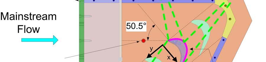
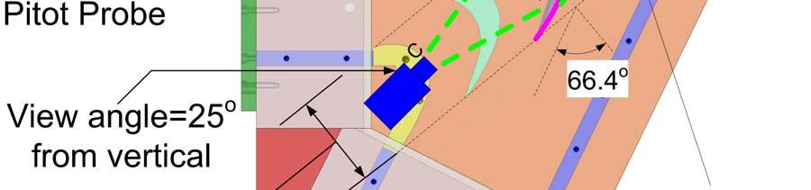
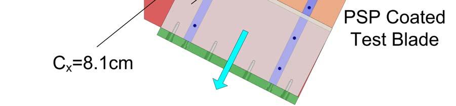
62 but the coolant consumption will substantially increase. Therefore, the mass flow ratio of 0.5% is chosen in current study. A labyrinth-like seal, typical of a stator-rotor seal found in gas turbine engines, was used for upstream platform cooling. The seal was grown from Accura 55 resin by stereolithography (SLA) process. SLA process allows complex geometries to be created in real quick time and at a much cheaper price. Typical SLA resins have a thermal conductivity of around 0.2W/m K. Two individual saw-toothed SLA pieces were placed side-by-side to give the seal its zigzag shape, Figure 4.2 The downstream half of the seal met the platform at an angle of 20º. The seal covered two passages of the cascade. A coolant plenum was constructed underneath the seal. Coolant entered the plenum from the two narrow sides and exited the seal after traveling through a metal screen. Additional cooling was offered on the platform by means of discrete holes. The filmcooling holes in the current study are line-up with the freestream direction. Past studies in the open literature have confirmed that the passage cross flow sweeps the film coolant from pressure side to suction side. The jet deflection results a wider coverage area, similar to the compound angle holes on the flat plate studies. The 0.635cm thick platforms were built from the same SLA resin. Figure 4.3 shows two different hole geometries; the designs with cylindrical holes and laidback fan-shaped holes. Sixteen holes are equally distributed into two rows and more concentrated on the pressure side of the passage one row is located along the mid-passage and the other row is offset from the pressure side of the platform surface by 6.35mm. All holes are inclined at 30 to the


63 47 Figure 4.2 Schematic of cascade blade platform Figure 4.3 Blade platform film-cooling slot and discrete hole platform surface
64 48 and oriented along the streamwise direction with a hole-to-hole spacing around 4d. The cylindrical holes have a diameter of 1.588mm with a hole length of 8d. The laidback fanshaped holes are featured with a lateral expansion of 10 from the hole axis and forward expansion 5 into the platform surface. The hole diameter in metering part of the shape holes is the same as that for the cylindrical holes. The expansion starts at 4d, resulting in a cross section area ratio of 3.85 between the hole exit and hole inlet. Due to the large pressure variation on the platform, it is hard to control the local blowing ratios through each cooling holes. To solve this issue, three separate coolant cavities are used. The coolant supplied to each cavity is independently controlled by its rotameter(s). Cavity I feeds hole 1 to 4; cavity II feeds hole 5 to 11; the rest holes are fed by cavity III. A honeycomb mesh, 7.62cm long with a cell size of 1.27cm, is put 1.78m upstream to the blade leading edge to obtain uniform velocity distribution. Flow conditions in adjacent passages of the center blade are ensured to be identical by adjusting the trailing edge tailboards for the cascade. The mainstream air is supplied by a centrifugal compressor that could deliver a volume flow rate up to 6.2m3/s. The volume flow rate is regulated by a frequency controller having an operational range of 0 to 60 Hz. The cascade inlet and exit velocities are set to be 96m/s and 156m/s corresponding to inlet and exit Mach numbers of 0.27 and 0.44, respectively. The Reynolds number based on the axial chord length and exit velocity is 750,000 and the overall pressure ratio (Pt/P) is 1.14 (where Pt is inlet total pressure and P is exit static pressure). Some of important dimensions of the cascade and mainstream flow conditions are listed in Table 4.1. The
65 49 coolant purge flow rate is generally considered as a percentage of the mainstream mass flow rate. A total of 6 sets of experiments are performed to study the effects of blowing ratio (M), density ratio (DR), and freestream turbulence intensity (Tu) on blade filmcooling effectiveness. Three average blowing ratios 1.0, 1.5, and 2.0 were selected for the tests. A summary of the experimental conditions is shown in Table 4.2. Table 4.1 Cascade geometry and mainstream flow conditions for blade platform film-cooling Cascade Geometry Blade height (cm) Axial chord length (cm) 8.13 Inlet area (cm 2 ) Exit area (cm 2 ) Pitch (cm) 7.69 Inlet angle ( ) 50.5 Total turning angle ( ) Exit angle ( ) 66.4 Mainstream Flow Conditions Inlet Mach No Inlet Reynolds No. 465,000 Exit Mach No Exit Reynolds No. 750,000 Pressure ratio (P t /P) 1.14 Boundary layer thickness (cm) 2.5 and 0.5 Average turbulence intensity 4.2% and 10.5% Integral length scale/c x 0.72 and 0.07
66 50 Table 4.2 Summary of experimental conditions for blade patform film-cooling Expt. # MFR (%) M DR Tu (%)
67 Results and Discussion Pressure Measurement on Platform The pressure and Mach number distribution on the platform are examined and shown in Figure 4.4. The pressure distribution on the platform surface is mapped using PSP and compared with static pressure data obtained by pressure taps. The match is found to be quite reasonable. It can be seen from the contour plot that the static pressure near the pressure side is higher than that near the suction side. This is the driving force of turbine work as well as the passage across flow. From the leading edge to trailing edge, the pressure gradually decreases; the mainstream flow is accelerated; Mach number increases. The outer pressure distribution is found to be highly non-uniform, which affects purge flow distribution along the slot as well as the local blowing ratio distribution from the discrete holes. From the suction side to pressure side along the purge slot, the outer pressure increases, the local coolant mass flow ratio decreases. The high outer pressure near the pressure side of the passage prohibits the coolant exiting from film cooling holes Adiabatic Film-Cooling Effectiveness Some common features of platform film-cooling are observed regardless of hole shapes, blowing ratio and other factors. It is clear that the effectiveness distribution by purge flow is skewed with more coolant appearing from the slot end close the blade suction side, indicating the non-uniform outer pressure as stated earlier and the purge flow is swept aside by the passage cross flow. The passage vortex (conceptually shown

68 (a) Pressure distribution (b) Mach number distribution Figure 4.4 Pressure and Mach number distribution without coolant injection 52
69 53 by a white helix), that originates at the blade leading edge and gains in strength as it travels downstream, forms a barrier that prevents the coolant from traveling downstream. At downstream film-cooling holes, coolant is deflected to the suction side of passage by the cross flow within the passage. Due to the jet deflection, the jets from the holes offset from the pressure side are not able to impinge to the blade pressure side. Therefore, the junction area between the platform and the blade pressure side is unprotected by the film-cooling. Moreover, the horseshoe vortex (conceptually shown in black helix) also makes the junction area between the platform and the blade leading unprotected Effect of Density Ratio The effectiveness contours plots for a range of density ratio with Configuration A and B are presented in Figures 4.5 and 4.6. Freestream turbulence, purge flow, and blowing ratio are fixed at 10.5%, 0.5%, and 1.5, respectively. For the cylindrical holes, as density ratio increases, the coolant traces are distinct and longer. The higher coolant momentum in the case of low density coolant facilities jet detachment from the platform resulting in lower film effectiveness whereas lower coolant momentum for high density coolant keeps the jet attached to the platform producing better film-cooling coverage. Similar observation can be seen for the shaped holes, the film-cooling effectiveness elevates with density ratio. The coolant distribution immediately downstream of the slot shows no significant variation with density ratio.
 DR=1.0, (b) DR=1.5, (c) DR=2.0")
70 54 (a) DR=1.0 M=1.5 Tu=10.5% MFR=0.5% (b) DR=1.5 M=1.5 Tu=10.5% MFR=0.5% (c) DR=2.0 M=1.5 Tu=10.5% MFR=0.5% Figure 4.5 Density ratio effect on adiabatic film-cooling effectiveness for Config. A (a) DR=1.0, (b) DR=1.5, (c) DR=2.0
71 55 (a) DR=1.0 M=1.5 Tu=10.5% MFR=0.5% (b) DR=1.5 M=1.5 Tu=10.5% MFR=0.5% (c) DR=2.0 M=1.5 Tu=10.5% MFR=0.5% Figure 4.6 Density ratio effect on adiabatic film-cooling effectiveness for Config. B (a) DR=1.0, (b) DR=1.5, (c) DR=2.0
72 Effect of Blowing Ratio Figures 4.7 and 4.8 show the film effectiveness distributions for a range of blowing ratio with Configuration A and B. The values of purge flow rate (MFR=0.5%), density ratio (DR=1.5), and freestream turbulence intensity (Tu=10.5%) are selected to simulate engine-like flow conditions. As expected in all cases, the same purge flow delivery produced identical coolant distributions downstream of the slot. Comparing two different geometry designs, it can be seen that the shaped holes offers a larger film coverage and higher effectiveness magnitude. The best film-cooling effectiveness for cylindrical holes is obtained at M=1.5. Further increases of blowing ratio results in jet penetration to the mainstream and reduces the effectiveness level. For the shaped holes, the film effectiveness increases with the increases of average blowing ratio. The hole exit area is enlarged for the shaped holes and the jet momentum reduces; the coolant jet is easier to stay close to the surface. In addition, the jets from the shaped holes create wider coolant traces and accumulate at the downstream Effect of Freestream Turbulence Intensity Depending on the combustor arrangement used in the industry, the turbulence intensity varies from 5% to 20% entering the turbine section. The present study performs the platform film-cooling measurements for both low freestream turbulence level (Tu=4.2%) and high freestream turbulence level (Tu=10.5%). The contours of filmcooling effectiveness for Configuration A and B are shown in Figures 4.9 and It can be clearly observed from the distribution around the film-cooling holes, the coolant
 M=1.0, (b) M=1.5, (c) M=2.0")
73 57 (a) M=1.0 DR=1.5 Tu=10.5% MFR=0.5% (b) M=1.5 DR=1.5 Tu=10.5% MFR=0.5% (c) M=2.0 DR=1.5 Tu=10.5% MFR=0.5% Figure 4.7 Blowing ratio effect on adiabatic film-cooling effectiveness for Config. A (a) M=1.0, (b) M=1.5, (c) M=2.0
74 58 (a) M=1.0 DR=1.5 Tu=10.5% MFR=0.5% (b) M=1.5 DR=1.5 Tu=10.5% MFR=0.5% (c) M=2.0 DR=1.5 Tu=10.5% MFR=0.5% Figure 4.8 Blowing ratio effect on adiabatic film-cooling effectiveness for Config. B (a) M=1.0, (b) M=1.5, (c) M=2.0
75 59 (a) Tu=4.2% DR=1.5 M=1.5 MFR=0.5% (b) Tu=10.5% DR=1.5 M=1.5 MFR=0.5% Figure 4.9 Turbulence intensity effect on adiabatic film-cooling effectiveness for Config. A (a) Tu=4.2%, (b) Tu=10.5%
76 60 (a) Tu=4.2% DR=1.5 M=1.5 MFR=0.5% (b) Tu=10.5% DR=1.5 M=1.5 MFR=0.5% Figure 4.10 Turbulence intensity effect on adiabatic film-cooling effectiveness for Config. B (a) Tu=4.2%, (b) Tu=10.5%
77 61 traces are longer and wider in the low turbulence case. At the elevated turbulence level, the coolant traces decay rapidly. The purge flow distribution is also affected by the level of freestream turbulence. Coolant emerges more uniformly from the slot at low turbulence. However, the purge flow can be carried further downstream and less skew at high turbulence. Generally, higher turbulence level in the mainstream indicates more mixing between the coolant and mainstream and reduces cooling performance Laterally Average Film-Cooling Effectiveness Figures 4.11 and 4.12 show the effect of blowing ratio, density ratio, and turbulence intensity on laterally averaged film-cooling effectiveness based on two different hole configurations. The points x/c x =0 and 1.0 correspond to the blade leading and trailing edges. The purge flow begins and exits the slot at x/c x =-0.15 and , respectively. It can be observed that that two cooling sources are clearly depicted on the plots: A purge flow cooling peaks at x/c x =-0.1 with magnitude of 0.95; film-cooling through discrete filmcooling holes after x/c x =0.35. Several peaks between x/c x =0.35 and 1.0 indicates numbers of pairs of holes between the blade leading and trailing edges. In Figures 4.11(a) and 4.12(a), it appears that unlike the discrete hole cooling, the purge flow cooling does not have a substantial impact by density ratio. On both cylindrical holes and shaped holes, the effectiveness level of discrete hole cooling increases with density ratio. For the cylindrical holes, the effectiveness enhancement due to heavier coolant is proportional. On the other hand, the improvement of effectiveness for the shaped holes becomes less significant as compared to the cylindrical holes. For
78 62 the purge flow cooling, since the effectiveness level is already very high (peaks at about 0.95 over the slot), the advantage of heavier density coolant is not obvious. Similar to contour plots, Figure 4.11(b), for cylindrical holes, the best film-cooling performance occurs at a blowing ratio of 1.5. The effectiveness levels increase about 40% when blowing ratio is increased from 1.0 to 1.5. With further increase to 2.0, the effectiveness levels drop sharply, even dropping below the level at M=1.0. In Figure 4.12(b), for shaped holes, the effectiveness levels increase at most 30% when blowing ratio is increased from 1.0 to 1.5. With further increases to 2.0, the enhancement of effectiveness levels is not significant. The upstream purge flow for both configurations produces nearly identical effectiveness levels since the mass flow rates are the same. As seen earlier in the contour plots, Figures 4.11(c) and 4.12(c) show that lower freestream turbulence leads to higher effectiveness levels throughout most of the platform, except at the downstream of the slot where the high turbulence flow display higher effectiveness. Close to the blade trailing edge, for cylindrical holes, the effectiveness levels with the low turbulence case are at most 40% higher than that with the high turbulence case. The shaped holes follow the same pattern but with smaller improvement in effectiveness.
79 63 (a) (b) (c) Figure 4.11 Laterally averaged effectiveness for Config. A (a) density ratio effect, (b) blowing ratio effect, (c) turbulence effect
80 64 (a) (b) (c) Figure 4.12 Laterally averaged effectiveness for Config. B (a) density ratio effect, (b) blowing ratio effect, (c) turbulence effect
81 Conclusions An experimental study was undertaken to measure the film-cooling effectiveness on a turbine blade platform within a five-blade linear cascade. The platform is cooled by purge flow from a typical stator-rotor seal combined with discrete hole film-cooling. The key feature of this study is the use of high coolant density to simulate engine-like operating conditions. Some of the main highlights from the present study are presented below: 1) High coolant-to-mainstream density ratio results in higher effectiveness levels. However, the improvement of film-cooling is less significant for the shaped hole design. 2) The effectiveness for the shaped holes increases with increase of blowing ratio, whereas an optimal blowing ratio of 1.5 exists for the cylindrical holes. 3) Platform film-cooling effectiveness is a function of freestream turbulence level. Higher the freestream turbulence, lower the effectiveness. 4) Overall the shaped holes provide wider film coverage and higher effectiveness level than the cylindrical holes. 5) The pressure side corner of the platform remains a difficult region to cool. It requires a new design of film-cooling hole layout and a modification of platform, such as endwall contouring.
82 66 5. TURBINE BLADE TIP FILM-COOLING 5.1. Introduction Large leakage flow occurs at the blade tip as a result of a high pressure differential from pressure to suction side. The hot leakage flow is the major cause of blade tip failures. To reduce the leakage flow and heat transfer on the tip, the blades of modern gas turbines typically have a recessed cavity at the tip and are called squealer tip blades. The groove acts as a labyrinth seal to increase flow resistance and thus reduces leakage flow. Many recent studies conducted the studies in a cascade environment with squealer tip blade. Azad et al. [53] used transient liquid crystal technique to study the heat transfer on the first stage blade tip of an aircraft engine turbine (GE-E 3 ). They compared squealer tip and plane tip geometry and concluded that the overall heat transfer coefficients were lower for squealer tip case. Azad et al. [54] also studied the effect of squealer geometry arrangement on gas turbine blade tip heat transfer and found that the location of the squealer rim could change the leakage flow and result in different heat loads to the blade tip. They also found that the suction side squealer provided best sealing to leakage flow among all the cases they studied. Kwak and Han [55, 56] examined heat transfer coefficient and film-cooling effectiveness on various film-cooling configurations and squealer tip geometries. Their results showed that the film-cooling effectiveness on the squealer tip was much higher than that on the plane tip. Chyu et al. [57] investigated heat transfer in a rectangular grooved tip model. They showed that the heat transfer in the
83 67 upstream end of the cavity was greatly reduced compared to the flat tip, however, at the downstream of the cavity, the heat transfer levels for the grooved tip were higher due to the reattachment inside the cavity Experimental Setup The schematic view of the test section and the blow-down loop is shown in Figure 5.1. The test section consisted of a 5-blade linear cascade with blade tip profiles. A 3X scaled model of the GE-E 3 blade is used with a blade span of 12.2cm and an axial chord length of 8.61cm. Figure 5.2 shows the blade profiles, the inlet and exit angles at design conditions. The blade tip and shroud definitions are also indicted in Figure 5.2. The test blade was made using stereo lithography (SLA). The four guide blades placed in the test section were made of aluminum. Figure 5.3 shows the film-cooing measurement blade with the internal passage geometry. The passages are numbered from 1 to 6 with passage 1 closest to leading edge and passage 6 closest to trailing edge. Coolant is supplied to the test blade through two loops with three serpentine passages with a 3mm wall thickness in each loop. Figure 5.4 shows the geometry and orientation of the film-cooling holes on the pressure side and on the squealer blade tip. Ten cylindrical tip holes with a diameter of 1.27mm (L/d=3.34) are provided on the tip. Out of these ten holes, four are drilled such that they break out at 45 along the camber line of the blade on the cavity floor. The remaining six holes are drilled at 45 along a curve offset to the suction surface of the blade by 5.08 mm and are equally spaced by 18.3mm. The holes are inclined to the cavity floor in the direction of
84 68 the bulk fluid flow. The first five tip holes are connected to loop 1 (near LE) and the remaining five to loop 2 (near TE). Nine film-cooling holes with a diameter of 1.27mm are located 9.5mm below the tip surface. The pressure side holes have a laidback and fan-shaped design expanding by 10 in the three directions ( ) with the expansion starting from the middle of the hole length, The hole-to-hole spacing is 8.9mm. The first three holes neat the leading edge are drilled at a radial angle of 45 to maximize the coolant spread whereas the remaining six holes are drilled at a compound angle of 45 to the blade span and 45 with respect to the airfoil pressure surface with L/d=4. The squealer tipped blade with recess of 2.1% of blade span is used in this study. The pressure side rim wall near the trailing edge is cutback by about 25% of the blade chord for the blade to allow accumulated coolant to escape.
85 69 Figure 5.1 Schematic of test section and blow down facility Figure 5.2 Definition of blade tip and shroud

86 Figure 5.3 Internal passage geometry of test blade 70

87 Figure 5.4 Orientation of tip and PS holes 71
88 Results and Discussion Film-Cooling Effectiveness Results Figure 5.5 shows the effectiveness results on squealer rims and cavity floor. On the cavity floor, the film coverage tends to be improving with the blowing ratio. Increase of blowing ratio from 1.0 to 1.5, the increase of effectiveness level is obvious; however, when the blowing ratio further increases to 2.0, the increase of effectiveness level is not significant. Jet lift-off can be observed around the holes near the leading edge at blowing ratio 2.0. Lift-off is indicated by a region of low effectiveness immediately downstream of the hole. Because the momentum of jet is too strong; it penetrates through the mainstream instead of forming a protection layer on the surface. As a result, effectiveness level decreases as blowing ratio elevates from 1.5 to 2.0 at the near leading edge portion Average Film-Cooling Effectiveness Results Figure 5.6 shows the comparison of average film-cooling effectiveness obtained from the three blowing ratios along the axial chord. The average values are obtained by averaging the effectiveness magnitudes at a given x/c x location. In general, the average effectiveness increases with increasing axial chord distance for all surfaces. The trend indicates that effectiveness increases with blowing ratio. Each spike represents the presence of a hole. Lift-off of the coolant jet can be observed for the holes closer to the leading edge as blowing ratio increases from 1.5 to 2.0 (up to X/C x =0.2).
89 73 Figure 5.7 shows the area-averaged film-cooling effectiveness results. It can be noted that on the blade tip surface, effectiveness level increases with blowing ratio, M = 2 shows highest effectiveness Conclusions A parametric study has been performed for measuring film-cooling effectiveness on a squealer blade tip with different blowing ratios. Effectiveness was measured on the cavity floor, rim, cavity rim walls and near tip pressure side. Effects of squealer cavity have been studied. Major findings from the experimental results are listed below: 1) In general, higher blowing ratios give higher effectiveness on the blade tip, M = 2.0 shows best results. 2) The cutback squealer rim results in high effectiveness in the trailing edge region of the blade tip as compared to a full squealer. 3) Coolant accumulation results in increasing effectiveness from blade leading edge to trailing edge.

90 74 (a) M=1.0 DR=1.0 (b)m=1.5 DR=1.0 (c) M=2.0 DR=1.0 Figure 5.5 Film-Cooling effectiveness distribution on blade tip
91 Figure 5.6 Averaged film-cooling effectiveness from experimental results 75
92 Figure 5.7 Area-averaged film-cooling effectiveness from experimental results 76
93 77 6. VANE SUCTION SIDE HEAT TRANSFER STUDY 6.1. Objectives of Vane Suction Side Heat Transfer This research is to study the effect of transonic flow on turbine vane suction side heat transfer without film-cooling using a Transient Liquid Crystal (TLC) method. Tests were performed in a five-vane annular cascade with a blow-down flow loop facility. The exit Mach numbers are controlled to be about 1.1, the test vane features 3 rows of radialangle cylindrical holes around the leading edge, and 2 rows of compound-angle shaped holes on the suction side Test Facilities for Heat Transfer Study A scaled model of the Honeywell vane was placed in the center of annular cascade. Test vane was manufactured by Stereolithography (SLA) process. Figure 6.1(a) shows the unique shape and cooling hole locations of the vane. It has a various height converges from leading to trailing edge. The leading edge of the test vane is equipped with three rows of showerhead film cooling holes; the middle row is aligned with the stagnation line. Three leading edge rows are staggered with respect to one another. Each showerhead row has 7 radial-angle cylindrical holes with a hole-to-hole spacing of s/d = 6.9. Two row of compound-angle shaped holes (SS1, SS2) on the suction side with a hole-to-hole spacing of s/d = 7.3. The shaped holes have a typical design of metering length and expansion angle in three directions. Coolant is delivered from three straight passages as shown in Figure 6.1(b). Flow in each passage is individually controlled by a rotameter, the schematic setup is shown in Figure 6.2.
94 78 During the blow-down test, the cascade exit air velocities were set at exit Mach number (Ma exit ) = 1.1. The exit velocity was continuously monitored using a Pitot-static pressure probe placed downstream of the cascade. The blowdown facility could maintain steady flow in the cascade for about 30 seconds. Compressed air stored in tanks entered a high flow digital control valve, which could maintain steady flow receiving downstream pressure feedback. The control valve could maintain a velocity within 2% of desired value. A grid was placed upstream of the cascade and generated turbulence level of 10% at test section inlet. The average length scale was approximately 1.5cm. To monitor the exit velocity, a Pitot-static probe is stationed 75% C x distance downstream of the test vane. Before applying liquid crystal to the test surface, it is coated with black paint. The black paint acts as a binder; neighboring vanes and the passages are also sprayed black to eliminate any stray reflection.
 hole locations (b)")

95 79 Figure 6.1 Test Vane (a) hole locations (b) coolant passage Figure 6.2. Schematic of setup for vane suction side film-cooling and heat transfer study
96 Results and Discussion Surface Initial Temperature The heat transfer coefficients are measured by recording the changing vane temperature and time using the transient liquid crystal technique. To perform the transient heat transfer test, the stator vane is preheated before the run. The vane was heated slowly until the surface temperature was in the range of 50ºC-60ºC. Three thermocouples mounted inside the vane internal coolant passages served as guide during the heating process. The initial suction surface temperature (T i ) is shown in Figure 6.3. As soon as the vane reaches the pre-set thermocouple temperatures, the heating procedure stops and the mainstream air is let in Heat Transfer Coefficient Results The mainstream temperature is kept at a constant value of 20ºC although the true representative of mainstream flow temperature is the adiabatic surface temperature. Also in the present calculations, a constant thermal conductivity of 0.47 W/m-K (20ºC) was used. Figure 6.4 shows the heat transfer coefficient contour plot on the vane suction surface obtained from experiment. Due to the limitation of viewing window, region before X/L=0.1 and region after X/L=0.7 are excluded. Results show that the heat transfer coefficients increase toward the trailing edge (or throat) as flow accelerates. A spanwise variation can be found due to passage and horseshoe vortices (i.e., endwall effect). There are high heat transfer region before X/L=0.1 at the leading edge, followed by a low heat transfer region where flow is developing and becoming transition.

97 81 Figure 6.3. Initial temperature on stator vane suction side Figure 6.4. Heat transfer coefficient on the vane suction side
Investigation of converging slot-hole geometry for film cooling of gas turbine blades
 Project Report 2010 MVK160 Heat and Mass Transport May 12, 2010, Lund, Sweden Investigation of converging slot-hole geometry for film cooling of gas turbine blades Tobias Pihlstrand Dept. of Energy Sciences,
FILM COOLING WITH FORWARD AND BACKWARD INJECTION FOR CYLINDRICAL AND FAN-SHAPED HOLES USING PSP MEASUREMENT TECHNIQUE. A Thesis ANDREW F CHEN
 FILM COOLING WITH FORWARD AND BACKWARD INJECTION FOR CYLINDRICAL AND FAN-SHAPED HOLES USING PSP MEASUREMENT TECHNIQUE A Thesis by ANDREW F CHEN Submitted to the Office of Graduate and Professional Studies
Study on Flow Fields in Variable Area Nozzles for Radial Turbines
 Vol. 4 No. 2 August 27 Study on Fields in Variable Area Nozzles for Radial Turbines TAMAKI Hideaki : Doctor of Engineering, P. E. Jp, Manager, Turbo Machinery Department, Product Development Center, Corporate
EXPERIMENTAL INVESTIGATION OF TURBINE BLADE PLATFORM FILM COOLING AND ROTATIONAL EFFECT ON TRAILING EDGE INTERNAL COOLING.
 EXPERIMENTAL INVESTIGATION OF TURBINE BLADE PLATFORM FILM COOLING AND ROTATIONAL EFFECT ON TRAILING EDGE INTERNAL COOLING A Dissertation by LESLEY MAE WRIGHT Submitted to the Office of Graduate Studies
Design and Test of Transonic Compressor Rotor with Tandem Cascade
 Proceedings of the International Gas Turbine Congress 2003 Tokyo November 2-7, 2003 IGTC2003Tokyo TS-108 Design and Test of Transonic Compressor Rotor with Tandem Cascade Yusuke SAKAI, Akinori MATSUOKA,
A Comparison of Cylindrical and Fan-Shaped Film-Cooling Holes on a Vane Endwall at Low and High Freestream Turbulence Levels
 W. Colban Combustion Research Facility, Sandia National Laboratories, Livermore, CA 94551-0969 e-mail: wcolban@sandia.gov K. A. Thole Department of Mechanical and Nuclear Engineering, The Pennsylvania
ADIABATIC EFFECTIVENESS MEASUREMENTS OF ENDWALL FILM-COOLING FOR A FIRST STAGE VANE
 Proceedings of ASME Turbo Expo 2004 Power for Land, Sea, and Air June 14-17, 2004, Vienna, Austria GT2004-53326 ADIABATIC EFFECTIVENESS MEASUREMENTS OF ENDWALL FILM-COOLING FOR A FIRST STAGE VANE D. G.
Chapter 6 Predictions of Platform Adiabatic Effectiveness
 Chapter 6 Predictions of Platform Adiabatic Effectiveness The turbine platform is relied upon to deal with significant amounts of thermal and mechanical stress as the blade rotates at relatively high rotational
17/11/2016. Turbomachinery & Heat Transfer Laboratory Faculty of Aerospace Engineering Technion Israel Institute of Technology, Israel
 17/11/2016 Turbomachinery & Heat Transfer Laboratory Faculty of Aerospace Engineering Technion Israel Institute of Technology, Israel 1 Motivation New challenges rise due to increase in demands from small
Predictions of Cooling From Dirt Purge Holes Along the Tip of a Turbine Blade
 Proceedings of ASME Turbo Expo 2003 Power for Land, Sea, and Air June 16 19, 2003, Atlanta, Georgia, USA GT2003-38251 Predictions of Cooling From Dirt Purge Holes Along the Tip of a Turbine Blade E. M.
Numerical simulation of detonation inception in Hydrogen / air mixtures
 Numerical simulation of detonation inception in Hydrogen / air mixtures Ionut PORUMBEL COMOTI Non CO2 Technology Workshop, Berlin, Germany, 08.03.2017 09.03.2017 Introduction Objective: Development of
to be published in: ASME Journal of Turbomachinery THE DESIGN OF AN IMPROVED ENDWALL FILM-COOLING CONFIGURATION
 ASME Paper 98-GT-483 to be published in: ASME Journal of Turbomachinery THE DESIGN OF AN IMPROVED ENDWALL FILM-COOLING CONFIGURATION S. Friedrichs BMW Rolls-Royce GmbH Dahlewitz, Germany H.P. Hodson and
IJSER. Mechanical Engg. Dept., NITK Surathkal,Mangalore, Karnataka, India
 ISSN 2229-5518 919 Mechanical Engg. Dept., NITK Surathkal,Mangalore, Karnataka, India tpashok@rediffmail.com Abstract - Gas turbine engines are highly dependent on development of blade cooling techniques
Effect of Stator Shape on the Performance of Torque Converter
 16 th International Conference on AEROSPACE SCIENCES & AVIATION TECHNOLOGY, ASAT - 16 May 26-28, 2015, E-Mail: asat@mtc.edu.eg Military Technical College, Kobry Elkobbah, Cairo, Egypt Tel : +(202) 24025292
Cooling the Tip of a Turbine Blade Using Pressure Side Holes Part I: Adiabatic Effectiveness Measurements
 J. R. Christophel K. A. Thole Mechanical Engineering Department, Virginia Polytechnic Institute and State University, Blacksburg, Virginia 24061 F. J. Cunha Pratt & Whitney, United Technologies Corporation,
A Computational Study of Axial Compressor Rotor Casing Treatments and Stator Land Seals
 Virginia Commonwealth University VCU Scholars Compass Theses and Dissertations Graduate School 2006 A Computational Study of Axial Compressor Rotor Casing Treatments and Stator Land Seals Charles C. Cates
Transmission Error in Screw Compressor Rotors
 Purdue University Purdue e-pubs International Compressor Engineering Conference School of Mechanical Engineering 2008 Transmission Error in Screw Compressor Rotors Jack Sauls Trane Follow this and additional
International Journal of Scientific & Engineering Research, Volume 5, Issue 7, July-2014 ISSN
 ISSN 9-5518 970 College of Engineering Trivandrum Department of Mechanical Engineering arundanam@gmail.com, arjunjk91@gmail.com Abstract This paper investigates the performance of a shock tube with air
Numerical Simulation of the Flow through the Rotor of a Radial Inflow Turbine
 THE AMERICAN SOCIETY OF MECHANICAL ENGINEERS 345 E. 47th St.. New York, N.Y. 10017 97;GT-90 The Society shall not be responsible for statements or opinions advanced in papers or eascussion at meetings
APPLICATION OF STAR-CCM+ TO TURBOCHARGER MODELING AT BORGWARNER TURBO SYSTEMS
 APPLICATION OF STAR-CCM+ TO TURBOCHARGER MODELING AT BORGWARNER TURBO SYSTEMS BorgWarner: David Grabowska 9th November 2010 CD-adapco: Dean Palfreyman Bob Reynolds Introduction This presentation will focus
FLOW CONTROL THROUGH VORTEX SHEDDING INTERACTION OF ONE CYLINDER DOWNSTREAM OF ANOTHER. Jonathan Payton 1, and *Sam M Dakka 2
 International Journal of GEOMATE, May, 2017, Vol.12, Issue 33, pp. 53-59 Geotec., Const. Mat. &Env., ISSN:2186-2990, Japan, DOI: http://dx.doi.org/10.21660/2017.33.2565 FLOW CONTROL THROUGH VORTEX SHEDDING
November 8, 2018 GAS TURBINE ENGINE SECONDARY FLOW SYSTEMS
 November 8, 2018 GAS TURBINE ENGINE SECONDARY FLOW SYSTEMS Agenda 1 What is Secondary Flow? Purpose for the Secondary Flow Systems Chargeable Vs Nonchargeable Flows Seals Selection and Leakage Effects
EFFECT OF SURFACE ROUGHNESS ON PERFORMANCE OF WIND TURBINE
 Chapter-5 EFFECT OF SURFACE ROUGHNESS ON PERFORMANCE OF WIND TURBINE 5.1 Introduction The development of modern airfoil, for their use in wind turbines was initiated in the year 1980. The requirements
Flow and Heat Transfer Analysis of an Inlet Guide Vane with Closed-loop Steam Cooling
 International Conference on Intelligent Systems Research and Mechatronics Engineering (ISRME 2015) Flow and Heat Transfer Analysis of an Inlet Guide Vane with Closed-loop Steam Cooling Siping Zhai 1, Chao
FLOW AND HEAT TRANSFER ENHANCEMENT AROUND STAGGERED TUBES USING RECTANGULAR VORTEX GENERATORS
 FLOW AND HEAT TRANSFER ENHANCEMENT AROUND STAGGERED TUBES USING RECTANGULAR VORTEX GENERATORS Prabowo, Melvin Emil S., Nanang R. and Rizki Anggiansyah Department of Mechanical Engineering, ITS Surabaya,
Heat transfer enhancement of a single row of tube
 Heat transfer enhancement of a single row of tube Takayuki Tsutsui 1,* 1 Department of Mechanical Engineering, The National Defense Academy, 1-10-20 Hashirimizu, Yokosuka, Kanagawa 238-8686 Japan Abstract.
Experimental Testing of a Rotating Detonation Engine Coupled to Nozzles at Conditions Approaching Flight
 25 th ICDERS August 2 7, 205 Leeds, UK Experimental Testing of a Rotating Detonation Engine Coupled to Nozzles at Conditions Approaching Flight Matthew L. Fotia*, Fred Schauer Air Force Research Laboratory
CFD Investigation of Influence of Tube Bundle Cross-Section over Pressure Drop and Heat Transfer Rate
 CFD Investigation of Influence of Tube Bundle Cross-Section over Pressure Drop and Heat Transfer Rate Sandeep M, U Sathishkumar Abstract In this paper, a study of different cross section bundle arrangements
Influence of Cylinder Bore Volume on Pressure Pulsations in a Hermetic Reciprocating Compressor
 Purdue University Purdue e-pubs International Compressor Engineering Conference School of Mechanical Engineering 2014 Influence of Cylinder Bore Volume on Pressure Pulsations in a Hermetic Reciprocating
NUMERICAL INVESTIGATION OF PISTON COOLING USING SINGLE CIRCULAR OIL JET IMPINGEMENT
 NUMERICAL INVESTIGATION OF PISTON COOLING USING SINGLE CIRCULAR OIL JET IMPINGEMENT BALAKRISHNAN RAJU, CFD ANALYSIS ENGINEER, TATA CONSULTANCY SERVICES LTD., BANGALORE ABSTRACT Thermal loading of piston
Heat Transfer Enhancement for Double Pipe Heat Exchanger Using Twisted Wire Brush Inserts
 Heat Transfer Enhancement for Double Pipe Heat Exchanger Using Twisted Wire Brush Inserts Deepali Gaikwad 1, Kundlik Mali 2 Assistant Professor, Department of Mechanical Engineering, Sinhgad College of
COMPUTATIONAL FLOW MODEL OF WESTFALL'S 2900 MIXER TO BE USED BY CNRL FOR BITUMEN VISCOSITY CONTROL Report R0. By Kimbal A.
 COMPUTATIONAL FLOW MODEL OF WESTFALL'S 2900 MIXER TO BE USED BY CNRL FOR BITUMEN VISCOSITY CONTROL Report 412509-1R0 By Kimbal A. Hall, PE Submitted to: WESTFALL MANUFACTURING COMPANY May 2012 ALDEN RESEARCH
Comparison of Measurements and Predictions for Blowing from a Turbine Blade Tip
 JOURNAL OF PROPULSION AND POWER Vol. 21, No. 2, March April 2005 Comparison of Measurements and Predictions for Blowing from a Turbine Blade Tip E. Couch, J. Christophel, E. Hohlfeld, and K. A. Thole Virginia
Proceedings of ASME TURBO EXPO 2004 Power for Land, Sea, and Air June 14-17, 2004, Vienna, Austria
 Proceedings of ASME TURBO EXPO 2004 Power for Land, Sea, and Air June 14-17, 2004, Vienna, Austria GT2004-53258 AXIAL TURBINE TIP DESENSITIZATION BY INJECTION FROM A TIP TRENCH PART 2: LEAKAGE FLOW SENSITIVITY
Vehicle Aerodynamics Subscription Development of Numerical Simulation Method of Flow Around Automobile Using Meshfree Method
 Vehicle Aerodynamics Subscription 2005-01-0544 Development of Numerical Simulation Method of Flow Around Automobile Using Meshfree Method 2005-01-0545 A Downforce Optimization Study for a Racing Car Shape
Aerodynamic Characteristics of Sedan with the Rolling Road Ground Effect Simulation System
 Vehicle Engineering (VE) Volume 2, 2014 www.seipub.org/ve Aerodynamic Characteristics of Sedan with the Rolling Road Ground Effect Simulation System Yingchao Zhang 1, Linlin Ren 1, Kecheng Pan 2, Zhe Zhang*
COMPARISON OF THE LEAKAGE CHARACTERISTICS OF THE STRAIGHT ANNULAR AND CONVERGENT SEALS. A Thesis SERAFETTIN USTUN
 COMPARISON OF THE LEAKAGE CHARACTERISTICS OF THE STRAIGHT ANNULAR AND CONVERGENT SEALS A Thesis by SERAFETTIN USTUN Submitted to the Office of Graduate Studies of Texas A&M University in partial fulfillment
EXPERIMENTAL INVESTIGATION OF THE FLOWFIELD OF DUCT FLOW WITH AN INCLINED JET INJECTION DIFFERENCE BETWEEN FLOWFIELDS WITH AND WITHOUT A GUIDE VANE
 Proceedings of the 3rd ASME/JSME Joint Fluids Engineering Conference July 8-23, 999, San Francisco, California FEDSM99-694 EXPERIMENTAL INVESTIGATION OF THE FLOWFIELD OF DUCT FLOW WITH AN INCLINED JET
Flow Behavior and Friction Factor. in Internally Grooved Pipe Wall
 Adv. Studies Theor. Phys., Vol. 8, 2014, no. 14, 643-647 HIKARI Ltd, www.m-hikari.com http://dx.doi.org/10.12988/astp.2014.4573 Flow Behavior and Friction Factor in Internally Grooved Pipe Wall Putu Wijaya
Impacts of Short Tube Orifice Flow and Geometrical Parameters on Flow Discharge Coefficient Characteristics
 Impacts of Short Tube Orifice Flow and Geometrical Parameters on Flow Discharge Coefficient Characteristics M. Metwally Lecturer, Ph.D., MTC, Cairo, Egypt Abstract Modern offset printing machine, paper
THE EFFECT OF BLADE LEAN ON AN AXIAL TURBINE STATOR FLOW HAVING VARIOUS HUB TIP RATIOS. Dr. Edward M Bennett
 THE EFFECT OF BLADE LEAN ON AN AXIAL TURBINE STATOR FLOW HAVING VARIOUS HUB TIP RATIOS Dr. Edward M Bennett ABSTRACT The effect of simple lean on an axial turbine stator was examined using a threedimensional
Foundations of Thermodynamics and Chemistry. 1 Introduction Preface Model-Building Simulation... 5 References...
 Contents Part I Foundations of Thermodynamics and Chemistry 1 Introduction... 3 1.1 Preface.... 3 1.2 Model-Building... 3 1.3 Simulation... 5 References..... 8 2 Reciprocating Engines... 9 2.1 Energy Conversion...
EFFECT OF SPOILER DESIGN ON HATCHBACK CAR
 EFFECT OF SPOILER DESIGN ON HATCHBACK CAR Ashpak Kazi 1 *, Pradyumna Acharya 2, Akhil Patil 3 and Aniket Noraje 4 1,2,3,4 Department of Automotive Engineering, School of Mechanical Engineering, VIT University,
DESIGN OF ACTIVE FLOW CONTROL AT THE WING/PYLON/ENGINE JUNCTION
 DESIGN OF ACTIVE FLOW CONTROL AT THE WING/PYLON/ENGINE JUNCTION A. PRACHAŘ, P. VRCHOTA / VZLU A. GEBHARDT, J. WILD / DLR S. WALLIN / KTH D. HUE / ONERA M. MINERVINO / CIRA Coordinator : Martin Wahlich
Gas Turbine Blade Tip and Near Tip Heat Transfer with Film Cooling
 Louisiana State University LSU Digital Commons LSU Master's Theses Graduate School 2011 Gas Turbine Blade Tip and Near Tip Heat Transfer with Film Cooling Gregory Kramer Louisiana State University and
(Refer Slide Time: 1:13)
") Fluid Dynamics And Turbo Machines. Professor Dr Dhiman Chatterjee. Department Of Mechanical Engineering. Indian Institute Of Technology Madras. Part A. Module-2. Lecture-2. Turbomachines: Definition and
Fluid Dynamics And Turbo Machines. Professor Dr Dhiman Chatterjee. Department Of Mechanical Engineering. Indian Institute Of Technology Madras. Part A. Module-2. Lecture-2. Turbomachines: Definition and
DEVELOPMENT OF TIP CLEARANCE FLOW DOWNSTREAM OF A ROTOR BLADE WITH COOLANT INJECTION FROM A TIP TRENCH
 DEVELOPMENT OF TIP CLEARANCE FLOW DOWNSTREAM OF A ROTOR BLADE WITH COOLANT INJECTION FROM A TIP TRENCH Debashis Dey Department of Aerospace Engineering The Pennsylvania State University University Park,
Structural Analysis Of Reciprocating Compressor Manifold
 Purdue University Purdue e-pubs International Compressor Engineering Conference School of Mechanical Engineering 2016 Structural Analysis Of Reciprocating Compressor Manifold Marcos Giovani Dropa Bortoli
Chapter 7: Thermal Study of Transmission Gearbox
 Chapter 7: Thermal Study of Transmission Gearbox 7.1 Introduction The main objective of this chapter is to investigate the performance of automobile transmission gearbox under the influence of load, rotational
Advanced Aerodynamic Design Technologies for High Performance Turbochargers
 67 Advanced Aerodynamic Design Technologies for High Performance Turbochargers TAKAO YOKOYAMA *1 KENICHIRO IWAKIRI *2 TOYOTAKA YOSHIDA *2 TORU HOSHI *3 TADASHI KANZAKA *2 SEIICHI IBARAKI *1 In recent years,
Effect of concave plug shape of a control valve on the fluid flow characteristics using computational fluid dynamics
 Effect of concave plug shape of a control valve on the fluid flow characteristics using computational fluid dynamics Yasser Abdel Mohsen, Ashraf Sharara, Basiouny Elsouhily, Hassan Elgamal Mechanical Engineering
Blockage Effects From Simulated Thermal Barrier Coatings for Cylindrical and Shaped Cooling Holes
 Christopher A. Whitfield Mechanical and Nuclear Engineering Department, The Pennsylvania State University, University Park, PA 16802 e-mail: christopher.whitfield@pw.utc.com Robert P. Schroeder Mechanical
Enhanced Heat Transfer Surface Development for Exterior Tube Surfaces
 511 A publication of CHEMICAL ENGINEERING TRANSACTIONS VOL. 32, 2013 Chief Editors: Sauro Pierucci, Jiří J. Klemeš Copyright 2013, AIDIC Servizi S.r.l., ISBN 978-88-95608-23-5; ISSN 1974-9791 The Italian
(1) Keywords: CFD, helicopter fuselage, main rotor, disc actuator
 Keywords: CFD, helicopter fuselage, main rotor, disc actuator") SIMULATION OF FLOW AROUND FUSELAGE OF HELICOPTER USING ACTUATOR DISC THEORY A.S. Batrakov *, A.N. Kusyumov *, G. Barakos ** * Kazan National Research Technical University n.a. A.N.Tupolev, ** School of
SIMULATION OF FLOW AROUND FUSELAGE OF HELICOPTER USING ACTUATOR DISC THEORY A.S. Batrakov *, A.N. Kusyumov *, G. Barakos ** * Kazan National Research Technical University n.a. A.N.Tupolev, ** School of
Prediction of Thermal Deflection at Spindle Nose-tool Holder Interface in HSM
 Prediction of Thermal Deflection at Spindle Nose-tool Holder Interface in HSM V Prabhu Raja, J Kanchana, K Ramachandra, P Radhakrishnan PSG College of Technology, Coimbatore - 641004 Abstract Loss of machining
Transient Thermal Analysis of Screw Compressors, Part III: Transient Thermal Analysis of a Screw Compressor to Determine Rotor-to-Rotor Clearances
 Purdue University Purdue e-pubs International Compressor Engineering Conference School of Mechanical Engineering 26 Transient Thermal Analysis of Screw Compressors, Part III: Transient Thermal Analysis
Engine Performance Analysis
 Engine Performance Analysis Introduction The basics of engine performance analysis The parameters and tools used in engine performance analysis Introduction Parametric cycle analysis: Independently selected
Analysis of a turbine rim seal cavity via 3D-CFD using conjugated heat transfer approach
 Analysis of a turbine rim seal cavity via 3D-CFD using conjugated heat transfer approach ZERELLI, N. - Heat Transfer Department MTU Aero Engines, 80995 Munich, Germany University: ISAE Institut Supérieur
Pressure Drop Distribution in Smooth and Rib Roughened Square Channel with Sharp 180 Bend in the Presence of Guide Vanes
 International Journal of Rotating Machinery, 10: 99 114, 2004 Copyright c Taylor & Francis Inc. ISSN: 1023-621X print DOI: 10.1080/10236210490276692 Pressure Drop Distribution in Smooth and Rib Roughened
FILM COOLING PREDICTIONS ALONG THE TIP AND PLATFORM OF A TURBINE BLADE
 FILM COOLING PREDICTIONS ALONG THE TIP AND PLATFORM OF A TURBINE BLADE Erik M. Hohlfeld Thesis submitted to the Faculty of the Virginia Polytechnic Institute and State University in partial fulfillment
Turbostroje 2015 Návrh spojení vysokotlaké a nízkotlaké turbíny. Turbomachinery 2015, Design of HP and LP turbine connection
 Turbostroje 2015 Turbostroje 2015 Návrh spojení vysokotlaké a nízkotlaké turbíny Turbomachinery 2015, Design of HP and LP turbine connection J. Hrabovský 1, J. Klíma 2, V. Prokop 3, M. Komárek 4 Abstract:
COMPRESSIBLE FLOW ANALYSIS IN A CLUTCH PISTON CHAMBER
 COMPRESSIBLE FLOW ANALYSIS IN A CLUTCH PISTON CHAMBER Masaru SHIMADA*, Hideharu YAMAMOTO* * Hardware System Development Department, R&D Division JATCO Ltd 7-1, Imaizumi, Fuji City, Shizuoka, 417-8585 Japan
The Pennsylvania State University. The Graduate School. Department of Aerospace Engineering AERODYNAMIC AND HEAT TRANSFER ASPECTS OF TIP AND CASING
 The Pennsylvania State University The Graduate School Department of Aerospace Engineering AERODYNAMIC AND HEAT TRANSFER ASPECTS OF TIP AND CASING TREATMENTS USED FOR TURBINE TIP LEAKAGE CONTROL A Dissertation
CFD analysis of heat transfer enhancement in helical coil heat exchanger by varying helix angle
 CFD analysis of heat transfer enhancement in helical coil heat exchanger by varying helix 1 Saket A Patel, 2 Hiren T Patel 1 M.E. Student, 2 Assistant Professor 1 Mechanical Engineering Department, 1 Mahatma
Single-phase Coolant Flow and Heat Transfer
 22.06 ENGINEERING OF NUCLEAR SYSTEMS - Fall 2010 Problem Set 5 Single-phase Coolant Flow and Heat Transfer 1) Hydraulic Analysis of the Emergency Core Spray System in a BWR The emergency spray system of
HEAT TRANSFER AND FILM COOLING ON A CONTOURED BLADE ENDWALL WITH PLATFORM GAP LEAKAGE
 Proceedings of ASME Turbo Expo 2015: Power for Land, Sea, and Air GT2015 June 15-19, 2015, Montreal, Canada GT2015-43301 HEAT TRANSFER AND FILM COOLING ON A CONTOURED BLADE ENDWALL WITH PLATFORM GAP LEAKAGE
International Journal of Scientific & Engineering Research, Volume 6, Issue 10, October ISSN
 International Journal of Scientific & Engineering Research, Volume 6, Issue 0, October-205 97 The Effect of Pitch and Fins on Enhancement of Heat Transfer in Double Pipe Helical Heat Exchanger 2 Abdulhassan
Simulation Studies on the Effect of Porous Twisted Plate Inserts on the Performance of Fire Tube Steam Packaged Boiler
 Simulation Studies on the Effect of Porous Twisted Plate Inserts on the Performance of Fire Tube Steam Packaged Boiler S. Hassan *,a, M. K. Roslim b and R. M. Zain c Mechanical Engineering Department,
Flow Visualization Tunnel. Owner s Manual. May 2009
 Flow Visualization Tunnel May 2009 AEROLAB LLC 2009 Contents Introduction... 3 Description... 3 Warnings / Precautions... 4 Tunnel Overview... 5 Main Control Panel... 6 Basic Operation... 8 Auxiliary Blower
THERMAL TO MECHANICAL ENERGY CONVERSION: ENGINES AND REQUIREMENTS Vol. I - Thermal Protection of Power Plants - B.M.Galitseyskiy
 THERMAL PROTECTION OF POWER PLANTS B.M.Galitseyskiy Department of Aviation Space Thermotechnics, Moscow Aviation Institute, Russia Keywords: Heat transfer, thermal protection, porous cooling, block cooling,
Numerical Study on the Flow Characteristics of a Solenoid Valve for Industrial Applications
 Numerical Study on the Flow Characteristics of a Solenoid Valve for Industrial Applications TAEWOO KIM 1, SULMIN YANG 2, SANGMO KANG 3 1,2,4 Mechanical Engineering Dong-A University 840 Hadan 2 Dong, Saha-Gu,
Plasma Assisted Combustion in Complex Flow Environments
 High Fidelity Modeling and Simulation of Plasma Assisted Combustion in Complex Flow Environments Vigor Yang Daniel Guggenheim School of Aerospace Engineering Georgia Institute of Technology Atlanta, Georgia
EFFECTS OF LOCAL AND GENERAL EXHAUST VENTILATION ON CONTROL OF CONTAMINANTS
 Ventilation 1 EFFECTS OF LOCAL AND GENERAL EXHAUST VENTILATION ON CONTROL OF CONTAMINANTS A. Kelsey, R. Batt Health and Safety Laboratory, Buxton, UK British Crown copyright (1) Abstract Many industrial
CFD ANALYSIS TO INVESTIGATE THE EFFECT OF LEANED ROTOR ON THE PERFORMANCE OF TRANSONIC AXIAL FLOW COMPRESSOR STAGE
 20th Annual CFD Symposium August09-0, 208, Bangalore, Karnataka, India CFD ANALYSIS TO INVESTIGATE THE EFFECT OF LEANED ROTOR ON THE PERFORMANCE OF TRANSONIC AXIAL FLOW COMPRESSOR STAGE AKASH M M Tech
A NOVEL DESIGN METHOD OF VARIABLE GEOMETRY TURBINE NOZZLES FOR HIGH EXPANSION RATIOS
 A NOVEL DESIGN METHOD OF VARIABLE GEOMETRY TURBINE NOZZLES FOR HIGH EXPANSION RATIOS Lei Huang 1, Hua Chen 2, * 1. National Laboratory of Engine Turbocharging Technology, North China Engine Research Institute,
Chapter 6. Supercharging
 SHROFF S. R. ROTARY INSTITUTE OF CHEMICAL TECHNOLOGY (SRICT) DEPARTMENT OF MECHANICAL ENGINEERING. Chapter 6. Supercharging Subject: Internal Combustion Engine 1 Outline Chapter 6. Supercharging 6.1 Need
Numerical Investigation of Film Cooling Effectiveness in Turbine Blades
 American Journal of Fluid Dynamics 2016, 6(1): 20-26 DOI: 10.5923/j.ajfd.20160601.03 Numerical Investigation of Film Cooling Effectiveness in Turbine Blades Madhurima Dey *, Prakhar Jindal, A. K. Roy Department
Experiment (4): Flow measurement
: Flow measurement") Introduction: The flow measuring apparatus is used to familiarize the students with typical methods of flow measurement of an incompressible fluid and, at the same time demonstrate applications of the
Introduction: The flow measuring apparatus is used to familiarize the students with typical methods of flow measurement of an incompressible fluid and, at the same time demonstrate applications of the
Thermal Stress Analysis of Diesel Engine Piston
 International Conference on Challenges and Opportunities in Mechanical Engineering, Industrial Engineering and Management Studies 576 Thermal Stress Analysis of Diesel Engine Piston B.R. Ramesh and Kishan
Stability Limits and Fuel Placement in Carbureted Fuel Injection System (CFIS) Flameholder. Phase I Final Report
 Flameholder. Phase I Final Report") Stability Limits and Fuel Placement in Carbureted Fuel Injection System (CFIS) Flameholder Phase I Final Report Reporting Period Start Date: 15 March 2007 Reporting Period End Date: 31 August 2007 PDPI:
Stability Limits and Fuel Placement in Carbureted Fuel Injection System (CFIS) Flameholder Phase I Final Report Reporting Period Start Date: 15 March 2007 Reporting Period End Date: 31 August 2007 PDPI:
Engineering Success by Application of STAR-CCM+ for Modern Gas Turbine Design
 STAR Japanese Conference 2013 December 3, Yokohama, Japan Engineering Success by Application of STAR-CCM+ for Modern Gas Turbine Design Norbert Moritz, Karsten Kusterer, René Braun, Anis Haj Ayed B&B-AGEMA
The Discussion of this exercise covers the following points:
 Exercise 3-3 Venturi Tubes EXERCISE OBJECTIVE In this exercise, you will study the relationship between the flow rate and the pressure drop produced by a venturi tube. You will describe the behavior of
ABSTRACT INTRODUCTION
 Wind tunnel investigation of waste air re-entry with wall ventilation P. Broas Technical Research Centre of Finland, Ship Laboratory, Tekniikantie 12, SF-02150, Espoo, Finland ABSTRACT A wind tunnel investigation
COMPUTATIONAL ANALYSIS OF TWO DIMENSIONAL FLOWS ON A CONVERTIBLE CAR ROOF ABDULLAH B. MUHAMAD NAWI
 COMPUTATIONAL ANALYSIS OF TWO DIMENSIONAL FLOWS ON A CONVERTIBLE CAR ROOF ABDULLAH B. MUHAMAD NAWI Report submitted in partial of the requirements for the award of the degree of Bachelor of Mechanical
Reduction of Self Induced Vibration in Rotary Stirling Cycle Coolers
 Reduction of Self Induced Vibration in Rotary Stirling Cycle Coolers U. Bin-Nun FLIR Systems Inc. Boston, MA 01862 ABSTRACT Cryocooler self induced vibration is a major consideration in the design of IR
Modern Approach to Liquid Rocket Engine Development for Microsatellite Launchers
 Modern Approach to Liquid Rocket Engine Development for Microsatellite Launchers SoftInWay: Turbomachinery Mastered 2018 SoftInWay, Inc. All Rights Reserved. Introduction SoftInWay: Turbomachinery Mastered
Research in Internal and External Aerodynamics for the Next Generation of Effcient Aircraft
 Research in Internal and External Aerodynamics for the Next Generation of Effcient Aircraft Huu Duc Vo Associate Professor Department of Mechanical Engineering École Polytechnique de Montréal 2017 National
LES of wind turbine wakes
 LES of wind turbine wakes... and an SD7003 Airfoil! Hamid Sarlak Fluid Mechanics Section, Department of Wind Energy, Technical University of Denmark, hsar@dtu.dk Wake Conference - 2017 Uppsala University
Experiments in a Combustion-Driven Shock Tube with an Area Change
 Accepted for presentation at the 29th International Symposium on Shock Waves. Madison, WI. July 14-19, 2013. Paper #0044 Experiments in a Combustion-Driven Shock Tube with an Area Change B. E. Schmidt
Effect of cavitation in cylindrical and twodimensional nozzles on liquid jet formation
 Effect of in cylindrical and twodimensional nozzles on liquid formation Muhammad Ilham Maulana and Jalaluddin Department of Mechanical Engineering, Syiah Kuala University, Banda Aceh, Indonesia. Corresponding
ABSTRACT I. INTRODUCTION III. GEOMETRIC MODELING II. LITERATURE REVIW
 2017 IJSRSET Volume 3 Issue 5 Print ISSN: 2395-1990 Online ISSN : 2394-4099 Themed Section: Engineering and Technology Performance Analysis of Helical Coil Heat Exchanger Using Numerical Technique Abhishek
Combined Effects of Wakes and Jet Pulsing on Film Cooling
 Kristofer M. Womack Ralph J. Volino e-mail: volino@usna.edu Mechanical Engineering Department, United States Naval Academy, Annapolis, MD 21402 Michael P. Schultz Naval Architecture and Ocean Engineering
Study of Inlet Guide Vanes for Centrifugal Compressor in Miniature Gas-Turbines
 Study of Inlet Guide Vanes for Centrifugal Compressor in Miniature Gas-Turbines Ronald Reagon R 1 Roshan Suhail 2, Shashank N 3, Ganesh Nag 4 Vishnu Tej 5 1 Asst. Professor, Department of Mechanical Engineering,
Visualization of Flow and Heat Transfer in Tube with Twisted Tape Consisting of Alternate Axis
 2012 4th International Conference on Computer Modeling and Simulation (ICCMS 2012) IPCSIT vol.22 (2012) (2012) IACSIT Press, Singapore Visualization of Flow and Heat Transfer in Tube with Twisted Tape
The influence of Air Nozzles Shape on the NOx Emission in the Large-Scale 670 MWT CFB Boiler
 Refereed Proceedings The 12th International Conference on Fluidization - New Horizons in Fluidization Engineering Engineering Conferences International Year 2007 The influence of Air Nozzles Shape on the
Computational flow field analysis of a Vertical Axis Wind Turbine
 Computational flow field analysis of a Vertical Axis Wind Turbine G.Colley 1, R.Mishra 2, H.V.Rao 3 and R.Woolhead 4 1 Department of Engineering & Technology Huddersfield University Queensgate Huddersfield,
Comparison of Swirl, Turbulence Generating Devices in Compression ignition Engine
 Available online atwww.scholarsresearchlibrary.com Archives of Applied Science Research, 2016, 8 (7):31-40 (http://scholarsresearchlibrary.com/archive.html) ISSN 0975-508X CODEN (USA) AASRC9 Comparison
EXPERIMENTAL INVESTIGATIONS OF DOUBLE PIPE HEAT EXCHANGER WITH TRIANGULAR BAFFLES
 International Research Journal of Engineering and Technology (IRJET) e-issn: 2395-56 Volume: 3 Issue: 8 Aug-216 www.irjet.net p-issn: 2395-72 EXPERIMENTAL INVESTIGATIONS OF DOUBLE PIPE HEAT EXCHANGER WITH
Multilayer Energy Dissipating Inlet Column in Center-Feed Clarifiers 1
 Multilayer Energy Dissipating Inlet Column in Center-Feed Clarifiers 1 References 6,276,537 08/21/2001 Esler et al 210/519 6,800,209 10/05/2004 Wright 210/801 Field of Invention Clarifiers are tanks where
THERMAL MANAGEMENT OF AIRCRAFT BRAKING SYSTEM
 ABSTRACT THERMAL MANAGEMENT OF AIRCRAFT BRAKING SYSTEM Shivakumar B B 1, Ganga Reddy C 2 and Jayasimha P 3 1,2,3 HCL Technologies Limited, Bangalore, Karnataka, 560106, (India) This paper presents the