~.r-t~--;: BMe SERVICE
|
|
|
- Emerald Skinner
- 5 years ago
- Views:
Transcription
1 ~.r-t~--;: BMe SERVICE


2 ,.... Contents ~~~~ QI Q,)..,... tq.!!! ro \\ Page No. Ii.2: c!= QI Qj..c::lVl Foreword \ 0 1 ts o~8::l B.M.C. Service Policy "\'.' ~ «... It 2 >..c ~ ~ QI ~'+- B.M.C. Warranty I ::E... " 4 C1. u c: o "CI..cC:lIIc: a:i Controls... L 8.!! c:i u.i o.oroto QI UJ ::l"cilll~ "CI Instruments and SWllcllf"; 10 l- QI Q. en «e Ci~ ~ VI Seats and Seat Bellc; ::. ',1 12 E «I- o tl; 0 c 0 :c en :5 RJ"O e- o Driving the Car ""I' 13 U U..c 0:: "0... liic:liiu ::l Locks and mtlngs...!: 16 1l ::J...,'_ u '- «C1. Heating and Vl'n!II.!!lon III CIl..c 0. :c ", 19 0 "c_u... CIl UJ ""'Oco..c Wheels and ryrc'i t::.... ci VI:E ::l::e z ~ 0 Maintenance Attelltiun !!! ~ ~.,1J Location of luhrlcatloll.11,,1 Maintenance Points >- 23 '0 UJ ~.!!!~~ 0:: QI... Lubrication 24 ~ u..c >:>. UJ... CIlQl -J c: :>. --J QI Cooling Sy!.tCIlI 26.oc:~ «VI ~oqliii 0 ljj QI a. Specifications Centre of book CIl..c'- Recor1llllendod I uhrlcl1i'!'i 30 Z.t:t3+oi:t: QI Ignition Syc;telll "O'OID !!! c: ro"ci ro 0 '.iii- Carburetter ond Air I ilt..r 32 Z QI CIl... ::lc: ~ Hydraulic Drnk,"; o c.!!! "CI CIII!ch 33 u z ~ ::l E~ QJ Suspension 37 LA: 0 0 VIlli ~uale Battery ~ z en ~~ 38!!? :;c:"5e ::l... Z Lamps and ruses -J IJl:!lVl~ uo 39 UJ ::E Q :5 en "CI.oVlc: :e; Miscellaneous 44 I 0:: Z ~ 1...QJ 11.: Care of Body 45 UJ 0 «.- VI ~ QI-d UJ en Z 0:: Ciro::l.oQl CIl.?:>... vi "Passport to Service" 46 I- 0.c..c... CI).~ >0. 0:: en... u (.) ljj llle 00. "After Sale Service Voucher" 0 Z e::.olll 47 Z UJ ::l CIl.l!!..c._ ci UJ 0:: «. ~::l -J ::I: roc: "Passport" Vouchers 49 0:: c:5 I- ci Z 0 QlC!C::. UJ CIlCll «z ::J UJ ~ 0..c:..c: " Passport" Schedules.. > t:~e2f u UJ «0:: 0 «I-~ J "Passport" Current Charges Inside bacli cove I


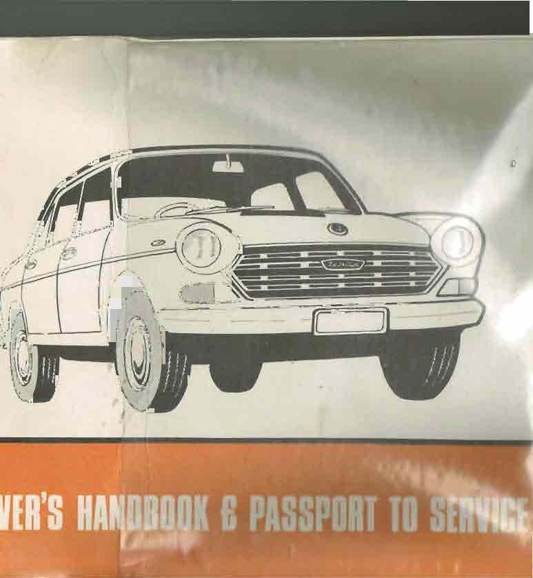
3 foreword This booklet, which is supplied with each new car, provides important information concerning the operation, care and maintenance of the vehicle_ It is, in fact, a " Passport to Service" and, as such, should be kept in a safe place in the car for presentation to an authorised 8.M.C. dealer whenever service is required. It must be produced when applying for warranty service as evidence of your entitlement. The Service Department of B.M.C. AUSTRALIA a Division of BRITISH LEYLAND MOTOR CORPORATION OF AUSTRALIA PTY. LIMITED South Dowling Street, Waterloo Bo 6, P.O., Waterloo, N.S.W., 2017 BMC


4 \ '-, ~- The After Sale Free Service. Following a thorough pre delivery service carried out by the dealer the owner is also entitled to an after sale free service at approimately 1000 miles. Th is service is im portant for the purpose of necessary adjustments during the running in period. Australia service policy At the same time the deale r will attend to.any items which might be causing the owner concern and, providing fault is established that has not been caused by accidental damage or misuse, there will be no charge other than for oils and materials. The owner is, therefore, requested to bring such matters which may not normally come under the definition of warranty to the dealer's attention at this time as subsequently they could be considered normal maintenance which is an owner responsibility. Owner Responsibility. The full implementation and security of the 8.M.C. warranty depends on the owner producing evidence of a satisfactory maintenance programme, as contained in the 8.M.C. " Passport to Ser'Jice" scheme. It is the owner's responsibility to draw any fau lt or malfunction in the vehicle to the 8.M.C. dealer's attention immediately it becomes apparent. Should delay in reporting such defects result in additional damage then this could well be considered the owner's responsibility. In the intere:;ts of owner's economy and taking into account the fact that all owners do not use their cars to the same etent it is necessary that the owner make the following simple items his own personal responsibility:- cool ing system levels (check cold) page 26 battery fluid level page 38 engine oil level page 24 tyre pressures page 28


5 3 B.M.C. Australia service policy Work under the warranty can only be effected by B.M.C. dealers. In general, items acceptable under warranty must be clearly related to a component fault and the warranty does not cover general running repairs and maintenance such as, but not necessarily confined to, the following:- Listed service schedules as in the passport to service. Wheel alignment-castor/camber adjustments. Steering rack adjustments and road wheel balancing. Engine tuning for performance and fuel consumption. Gear change, and other control adjustments. Clutch lining wear. BRITISH Cooling and fuel system cleaning. Brake lining wear. Bleeding and adjusting of system. Tyre wear. General t ightening of body and chassis components. Body adjustments-door locks, etc. Body finish-paintwork and trim wear and tear. Broken or scratched glass. Replacement of ependable items such as lamp bulbs, spark plugs, distributor points and condensers, and starter brushes, etc. LEYLAND BMC SERVICE

 are delivered to the first owner user thereof it will echange or repair any part which needs replacement or repair by reason of defective material or")


6 B.M.C. Australia warranty 1. WARRANTY. Subject as mentioned below B.M.C. Australia (hereinafter called 'the Firm') warrants that for a period of 12 MONTHS or 12,000 MILES whichever is the earlier or 12 MONTHS only in the case of a tractor from the date on which the Goods (as defined below) are delivered to the first owner user thereof it will echange or repair any part which needs replacement or repair by reason of defective material or workmanship in manufacture provided the need for replacement or repair is not due to abuse or lack of maintenance or comes under the heading of normal maintenance replacement or repair., Second-Hand Goods. A second or subsequent owner-user of the Goods will be entitled to claim under the terms of this Warranty subject to such claim being submitted within a period of 12 Months or 12,000 Miles or 12 Months only in the case of a tractor from the date on which the Goods are delivered to the f irst owner-user thereof. 2. LABOUR COSTS. The owner-user will not be charged for the removal and/or replacement of any part found to be defective but only if such removal and/or replacement is carried out by an authorised Distributor/Dealer (as defined below). 3. LIMITATIONS. No claim will be met under this Warranty if the Goods are or have been:- (a) used for competitions, racing, or record attempts, or otherwise than for the private or genuine commercial use of the owner-user and any previous owner-user; (b) purchased or acquired when new from a source other than a Distributor/Dealer or a subsidiary company of British Leyland Motor Corporation of Australia Ply. Limited; (c) damaged by wear and tear, inadequate maintenance, neglect or improper use; (d) altered outside the Firm's works or fitted with any part not sold or approved by the Firm; (e) altered by the removal or change of the Firm's identification numbers or marks or by unauthorised interference with the speedometer instrument; or (f) as respects a chassis or part of a chassis fitted with a body or equipment which in the opinion of the Firm is unsuitable. 4. EXCLUSIONS_ This Warranty is given in lieu of all warranties, conditions and liabilities whatsoever given by the Firm, its servants or agents or implied by common law, statute, or otherwise all of which shall accordingly be ecluded. Furthermore the Firm, its servants and agents shall not be liable for any claim for personal injuries or consequential liability, damage, or loss howsoever caused.
 Any owner-user claiming under this Warranty must: (i) In the case of the first owner user immediately upon discovery of the alleged defect return the part or parts complained of to the")
 If circumstances prevent action as in (i) above immediately upon discovery of the alleged defect return the part or parts complained of to a Distributor/ Dealer of British Leyland Motor")
 Furnish to the Distributor/Dealer Or subsidiary Company particulars of the Goods and the chassis/ serial number and the engine number of the Goods as shown on the manufacturer's identification")
 Send therewith full particulars of the claim and the reason therefor, stating in such particulars the date of purchase and the name and address of the Distributor/Dealer or subsidiary Company")
7 8.M.C. Australia warranty 5. PROCEDURE FOR CLAIMS. (a) Any owner-user claiming under this Warranty must: (i) In the case of the first owner user immediately upon discovery of the alleged defect return the part or parts complained of to the Distributor/Dealer or subsidiary Company as herein mentioned from whom t he Goods were purchased. (ii) If circumstances prevent action as in (i) above immediately upon discovery of the alleged defect return the part or parts complained of to a Distributor/ Dealer of British Leyland Motor Corporation ot A ustralia Pty. Limited. Ciii) Furnish to the Distributor/Dealer Or subsidiary Company particulars of the Goods and the chassis/ serial number and the engine number of the Goods as shown on the manufacturer's identification plate. (iv) Send therewith full particulars of the claim and the reason therefor, stating in such particulars the date of purchase and the name and address of the Distributor/Dealer or subsidiary Company from whom the goods were purchased when new. (b) The judgment of the Firm in all cases of claims shall be final and conclusive and the Purchaser sh all accept its decision on all questions as to defects and the echange of a part or parts. Unless otherwise requested, the alleged defective parts may be scrapped after 14 days of the notification of the Firm's decision. 6. DEFINITIONS. For the purpose of this Warranty, the following words shall have the meanings set o ut below : 'Goods' means new vehicles or parts thereof, including replacement parts manufactured by or supplied by the Firm as part of the standard equipment of such vehicles as well as non standard accessories a pp roved by the Firm but not tyres. Where special bodywork or equipment has been fitted at the request of the owner user but only after approval by the Firm as being suitable for fitting to the v hlcle concerned, this Warranty shall continue to etend to that portion of the original Goods as sold but cluding such bodywork or equipment and the approval by the Firm of such bodywork or qulpment shall not be taken to imply that the Firm in any way includes the bodywork or equipment WIthin t he t erms of this Warranty. 'OJ t ributor/ Dea le r' means a person, firm, or Company u nder contract with the Firm or a subsidiary o f the Firm to supply or service Goods. B.M.C. AUSTRALIA a Division of BRITISH LEYLAND MOTOR CORPORAT ION OF AUSTRALIA PTY. LIMITED South Dowling Street, Waterloo, N.S.W., 2017 BRITISH LEYLAND BMC SERVICE 5


8 8.M.C. Australia warranty transient warranty Travelling owners, or those who have changed their place of residence, can readily obtain warranty assistance from any authorised 8.M.C. dealer, provided they produce the handbook originally issued with the vehicle and the attention required is under the terms of the warranty. It is preferable for warranty attention to be given by the selling dealer as part of his obligation and if the owner is only temporarily absent from his area such requests for assistance are best confined to troubles of a "breakdown" or essential nature. alternative warranty service arrangements Should the owner reside in an area distant from his selling dealer and wish to have warranty service carried out by a more conveniently located 8.M.C. dealer, it will be necessary for such authority to be given by the selling dealer, who must then make arrangements with the dealer nominated by the owner. It is preferable for warranty attention to be given by the selling dealer as, apart from being his obligation, it also gives him an opportunity to display his keen personal interest in the owner as a customer. repair charges Charges for all repair work carried out by 8.M.C. dealers are based on the 8.M.C. schedule of repair times. Furthermore, at the 8.M.C. dealer the owner has t he added advantage of specialised 8.M.C. equipment, factory trained mechanics and approved parts bearing the same warranty as the new veh icle. 6

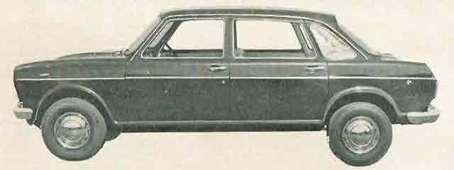

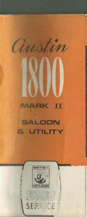
9 t~oo MARK II First introduced October, 1968
.")

10 controls l. Hand brake. Pull lever upwards to apply rear brakes. To release the hand brake pull the lever upwards slightly, dej:ress the lever button, and push the lever down. Hand brake (Utility). Pull lever to apply rear brakes. Release by pulling lever and by turning handle anti clockwise to free ratchet and then push forward. (NOTE: Located below centre dash console-not illustrated). manual gearbo models Gear lever. The gear positions are indicated on the knob. Lift to engage reverse. Clutch pedal. Depress fully to enable the desired gear to be selected. Brake pedal. Operates the hydraulic brakes on all four wheels. The rear stop warning lamps operate automatically when driving. Accelerator pedal. Depress to increase engine speed. Choke. Pull to assist starting from cold. Horn. Press the centre button of the steering wheel to sound the horn. Direction indicator flasher switch. Push downwards for right hand turn indication and push upwards for left hand turn indication. The indicator is self cancelling. The high beam may be flashed by moving the lever towards steering wheel. Headlight dip switch. Repeating type, low beam on one application and high beam on the net. Bonnet release. To open the bonnet pull to release the bonnet catch. The final release from the safety catch is made from outside at the front of the vehicle. (Refer locks and fittings. ) 8
. 2.")


11 controls 1. Hand brake. Pull lever to apply rear brakes. Release by pulling lever and by brake pull the lever upwards slightly, depress the lever button, and push the lever down. Hand brake (Utility). Pull lever to apply rear brakes. Release by pulling lever and by turning handle anti-clockwise to free ratchet and then push forward. (NOTE: Located be low centre dash console-not illustrated). 2. Brake pedal. Operates the hydraulic brakes on all four wheels. The rear stop warning lamps operate automatically when driving. 3. Accelerator pedal. Depress to increase engine speed. 4. Choke. Pull to assist starting from cold. 5. Horn. Press the centre button of the steering wheel to sound the horn. 6. Direction indicator flasher switch. Push downwards for right hand turn indication and push upwards for left hand turn indication, the indicator is self cancelling. The high beam may be flashed by moving the lever towards the steering wheel. automatic transmission models 7. Headlight dip switch. Repeating type, low beam on one application and high beam on the net. 8. Bonnet release. To open the bonnet pull to release the bonnet catch. The final release f rom the safety catch is made from outside at the front of the vehicle. (Refer locks and fittings.) 9. Gear selector quadrant. Provides selection of the transmission operation range. Refer to "driving instructions" for correct operation. 9

. The ignition warning light glows when the ignition is switched on and the alternator is not charging.")

12 1. Ignition and starter switch. To switch on ign ition, turn the key to the right until a slight resistance is felt. Further movement will start the engine, release the key as soon as the engine starts. 2. Lighting switch. A two position switch. Press lower edge to operate. The first position controls side and rear lamps, the second position controls head lamps. 3. Speedometer. This instrument indicates vehicle road speed by means of a ribbon which transverses the face. 4. Ignition warning light (red). The ignition warning light glows when the ignition is switched on and the alternator is not charging. If the light continues to glow whilst driving check for a loose or broken fan belt or a fault in the charging system. 5. Windscreen wiper switch. Press the lower edge to operate. The blades are parked automatically when the switch is in the central position. 6. Windscreen washer. Pump the button on the fascia panel to operate the washers. To avoid scratching a dirty windscreen it is advisable to use the washers before the wipers are switched on. 7. Oil pressure warning light (amber). The light glows when the ignition is switched on and fades out after the engine has been started. Low oil pressure or seriously insufficient oil in the engine is indicated by an amber glow when the engine is running.


13 instruments and switches I 9. Panel light switch. The panel lights will only function when the lighting switch is at or past its first position. To illuminate the instruments push the tumbler arm towards the front of the car..0. Headlight main beam warning light (blue). The light will glow when the headlights are switched on in the main beam position.,. 1. Fuel gauge. the tank. The fuel gauge indicates the ilpproimate quantity of fuel in.2. Total mileage indicator. Located in the centre of the speedometer it records total mileage travelled by the vehicle. ~ 3. Coolant temperature gauge. The coolant temperature is indicated on the temp rature gauge on the left of the instrument cluster. Any sudden IIPW, rd change beyond normal in the reading calls for immediate II1V stigatlon. BMC SERVICE 11


14 seats and seat belts Front seats. Both front seats are fully adjustable for leg length and back rest positions. The two separate adjustments are spring loaded and self-iocking_ The diagram shows clearly the two controls. When operating the back rest control lever it is advisable to relieve the back rest of driver or passenger weight. The back rests are completely reclinable to form a bed with the seat in the fully forward posit ion. Seat belts. The driver and front passenger seats are provided with individual lap and sash type seat belts. The rear seats are provided with in-built anchorage points and seat belts may be obtained from any authorised B.M.C. dealer. Fastening of belts. The belt is fastened by inserting the tongue into the buckle until a positive click is heard. Correct wearing of belts. The belts should be worn with the long belt crossing the chest diagonally and the buckle resting on the hip nearest the centre of the car. When correctly adjusted the lap portion should be comfortably tight and it should be possible to just pass a closed fist between the chest and the upper strap. The strap lengths are adjustable by sliding the belt through the fittings at the lower anchorage points for the long belt and through the buckle for the short belt. In order to gain the maimum protection from seat belts always ensure that the belts are correctly adjusted. Caution. Make sure that the short belt being used is attached to the side of the tunnel farthest from the wearer. Releasing of belts. To release the belt press the buckle button and eert a slight body pressure aga inst the belt. The buckle assembly will release. When the seat belts are not in use they should be stowed in the door pillar clip to prevent accidental damage and ensure safe eit and entry for the occupants of the car. Cleaning of belts. The belts may be cleaned with a warm soapy sponge. Do not dye or bleach as this may adversely affect the characteristics and strength of the webbing. Warning. Seat belts will give valuable protection in most accidents. If the belt becomes frayed or its strength is doubted in any way it should be replaced. Belts and anchorages should be checked frequently. 12


15 13 driving the car Driver Safety check windshield cleanliness check seat position check driving mirrors fasten safety belts observe road and traffic conditions and act accordingly Vehicle Safety check tyre pressures check cooling system levels check engine oil leaks check hydraulic fluid levels ensure maintenance schedules are followed Safety Is In Your Hands remember always:- a. be alert b. study the traffic conditions c. keep your vehicle efficient The new car Care taken in driving the new car in its early life will repay in greater efficiency later. The engine has been carefully assembled and tested before leaving the factory. Following which the selling dealer has caref ully prepared and rechecked the entire vehicle before delivery. It is suggested that for the first 500 miles the speed should not eceed 50 mph ecept for short periods. The car may be driven normally but the best performance must not be epected until the car is fully run in. The running in period is usually considered as 2000 miles. Driving the car with manual transmission The gear positions are clearly shown on the top of the gear lever knob. All the forward gears are equipped with synchromesh action to ensure smooth, easy gear changes. Lift to engage reverse. Starting the engine. Ensure that the gear lever is in the neutral position and that the hand brake is applied. If the engine is cold pull out the choke control. A little practice will determine the eact amount. Turn the ignition key fully to the right and release it as soon as the engine starts. Do not use the choke if the engine is hot. Push in the choke control completely as soon as the engine will run f reely without its use. Check to ensure that the ignition and oil pressure warning lights are not glowing. Driving hints. Do not attempt to start the engine whilst in gear. Do not leave the ignition switch on when the engine is not running. Do not slip clutch in traffic or when travelling uphill. Do not use the clutch pedal as a footrest. Do not coast vehicle with a gear engaged and the clutch held depressed. Do not under any circumstances run the engine in a closed garage or similar restricted atmosphere. The ehaust fumes are highly poisonous and if inhaled, will quickly produce grave, if not fatal results.


16 driving the car Driving the car with automatic transmission Selector positions. The selector lever mounted on the fascia panel controls the operation of the transmission. The lever positions are indicated on the quadrant which is marked 'P' 'R' 'N' ' 0' and 'L'. Starting the engine. The engine may only be started with the selector lever in the 'P' or 'N' position. If the engine is cold pull out the choke control. A little practice will determine the eact amount. Do not use the choke if the engine is hot. Turn the ignition key fully to the right and release it as soon as the engine starts. Normal driving. The selector lever may be moved frec)ly between '0' and 'N' but to select 'L', ' R' or 'P' the lever must be deflected to the left against spring pressure. ' P' park position: no engine power is transmitted to the wheels and the transmission is locked mechanically. When the car is to be left unattended it is advisable to engage the ' P' position. Do not engage 'P' unless the vehicle is stationary. 'R' reverse with full engine braking. Do not select 'R' when the car is moving forward. 'N' neutral no engine power is t ransmitted to the wheels. '0' with the selector in the ' 0' position all three forward ratios are available and are engaged automatically and progressively according to vehicle speed and accelerator position. Minimum accelerator pressure will result in low speed up changes. Rapid overtaking or hill climbing may be obtained by depressing the accelerator pedal beyond its normal travel into the kick down position. Kick down changes are under the driver's control ecept that the maimum down change speeds are preset to give optimum performance without overspeeding the engine. It is not necessary to move the selector lever from the '0' position when the vehicle is temporarily stationary. The normal forward creep may be held with a light application of the foot brake. 14


.")
17 driving the car 'L' provides a locked position for the low ratios which gives appropriate engine braking for descending a very steep hill. The road speed should be reduced to below 55 m.p.h. before selecting 'L' which will then provide the intermedi ate ratio until the road speed falls below 5 m.p.h. when low will be automatically engaged and held. Driving hints. Do not hold the car on an upgrade by accelerating the engine ecessively. Use either the hand or foot brake as required. Do not drive with the accelerator and brake pedals depressed. Do not engage 'P' or 'R' whilst the vehicle is moving. Do not engage 'L' or '0' whilst the vehicle is moving back wards. WI! n towing a caravan or heavy trailer always select 'L' before lif. l:ending steep hills. Driving on soft surfaces. Should the front wheels fail to grip under mud or slush conditions traction may be regained by rocking the car backwards and forwards by alternatively select ing 'R' and '0' with a small throttle opening. This car cannot be tow started. Special towing note (automatic transmission). If for some reason it be found necessary for the vehicle to be towed it is preferable that the front wheels be suspended. If front suspended towing is not possible the following must be observed:- The selector lever must be in the 'N' position. Three pints etra of the approved transmission fluid must be added to the automatic transmission. The distance towed must not eceed 40 miles. The towing speed must not eceed 30 m.p.h. at any time. Fa ilure to observe all the above precautions may result in damage to the automatic transmission. 15


18 locks and fitting Bonnet lock. To open, pull the release handle under the parcel shelf, net, from the front of the car release the safety catch by eerting slight pressure downwards on the bonnet and pull the safety catch handle forward. Checked and lubricated in passport service each 6000 miles. Bonnet support. As the bonnet is raised the support stay will automatically spring into engagement and hold the bonnet in the open position. To close, raise the bonnet slightly, push the catch on the support arm to release the lock ing mechanism, then lower bonnet and apply pressure until the safety catch and bonnet lock are heard to engage. Windshield wiper blades. To ensure that the windshield is wiped as clean as possible the blade rubbers should be renewed each year. To release the blade from the arm first lift the arm assembly away from the screen, push apart the retaining spring and socket to enable the blade to be withdrawn. 16


 to render the interior handle")
19 locks and fittings Door locks. Both front doors can be locked with the ignition key. To lock. turn key towards front of car and then return it to upright position. To unlock. turn key towards rear of car and then return it to upright position. Door controls. To lock either front door from the inside push the sill locking button down wards. If a button is pushed down with the door open closing the door will return the button to the unlocked position on the front doors but not on the rear doors. Children's safety lock. Push the lever down (see inset) to render the interior handle inoperative. Eamined and lubricated in passport service each 6000 miles. Rear window. To open the window pull the toggle catch forward and push outwards. Close the window by pulling the centre of the catch inwards and then backwards until the catch snaps into the locked position. 17


20 locks and fittings Boot lock. To open, insert the key, turn anticlockwise and push the button. Opening the lid switches on the luggage compartment light. To lock, insert the key and turn clockwise. The key differs from the ignition key. Checked in passport service each 6000 miles. Fuel Filler The fuel filler cap is combined with the access panel located to the rear of the left hand rear wheel. To open insert the ignition key and turn clockwise. Checked in passport service each 6000 miles. 6
 under each vent.")

. Air Flow Closed: Control fully to the left.")
21 heating and ventilation Fresh air ventilating system. Fresh air is provided from air vents on the fascia panel. The volume of air entering the car may be individually controlled by either driver or passenger with the lever (3) under each vent. The direction of air flow can be individually controlled by adjusting the vertical and horizontal deflectors (1 and 2) on each vent. Heater control system. The heater unit will heat and ventilate the interior of the car and demist or de:rost the windscreen. The air supply may be at ambient temperature or heated from the engine cooling system. Temperature and air distribution are regulated by separate controls at the centre of the parcel rail. Air temperature (left hand control). Cold: Control fully to the left. Hot: Control fully to the right. Select intermediate position to vary the heat output. Air distribution (right hand control). Air Flow Closed: Control fully to the left. Air Flow to Screen: Control to centre position. Air Flow Through Car: Control fully to the right. Note an intermediate stop between the Screen and Car positions will allow air flow through both vents. Air boost (centre control). O):erates a blower incorporated in the heater and should be used when the car is travelling slowly, is stopped or in etreme weather conditions to augment the supply of air to the heater. Do not operate the blower when the air distribution control is in the "closed" position. Full heat output will not be available until the engine has reached its normal running temperature. The most effective use will be made of the ventilation, heating or demisting available if advantage is taken of the different air circulations induced within the vehicle interior by regulating the vehicle door or rear vent windows. 19


22 Wheels and tyres. Tyres are a major factor in road safety. The original equipment tyres fitted have been selected to enable normal passenger requirements and adequate loads to be carried. Tyres are vulnerable to abuse, damage by accident or incorrect maintenance and need to be inspected regularly. Sharp objects such as broken glass or pointed stones should be removed before full penetration is made. Modern vehicles are sensitive to road wheel balance and for this reason wheels and tyres are balanced at the factory. Normal wear and tear and road conditions may cause an out-of-balance condition to develop. Th is must be corrected in the interests of safety, road handling and the li fe of steering and suspension components as well as tyres. Road conditions and minor accidents may influence wheel alignment adversely. Adjustment may be necessary to correct the condition in order to ensure safety and long tyre life. The rate of tyre wear depends on many factors such as driving speeds, cornering, vehicle loading, road conditions, etc. In addition, tyres wear at different rates depending on their position on the vehicle. Depending on the observed condition of the tyres, a rotation of the road wheels may be recommended. The spare wheel may be included in this rotation to ensure that tyre wear is shared by all five tyres. The dealer will advise of the need for wheel balancing, rotation or an alignment check as a result of his observations during routine servicing. Tyre condition is checked in each passport service every 3000 miles or three months. Tyre pressures. The recommended pressures should be maintained at all times (refer centre of the book). Pressure checks should be carried out before the tyres become warm from a long run. Do not deflate to correct the pressure during a long run. Inflation pressures should be checked once a week or prior to a long journey. Do not neglect the spare. Any unusual pressure loss should be investigated. Remember, the appearance of radial ply tyres is deceptive, always use a pressure gauge when eamining for correct inflation. Valve caps should always be replaced using finger pressure only. The caps ensure a second seal should the valv e core become loose or fail. They also eclude dirt and moisture. One wheel is supplied with a metal key cap which c(;ln be used to tighten or replace a valve core.

. The spare wheel is cradled under the rear of the tray.")


23 wheels and tyres Spare wheel. The spare wheel is carried in a tray below the luggage compartment floor. To release, lift mat and place the wheel brace in the retaining bolt socket and turn anti clockwise. When replacing the wheel ensure that the valve is accessible, check tyre pressure regularly. Pressure checked in passport service each 3000 miles or three months. Spare wheel (utility). The spare wheel is cradled under the rear of the tray. To unlock the wheel retainer insert the key and turn clockwise. Slacken the knurled hand nut and push forward to clear the cradle. A handle is provided on the cradle. Changing a wheel. Apply the handbrake and remove the hub cover as shown by inserting the lever provided, directly opposite the valve, under the outer rim and prise off. Place the jack fully into the sill aperture nearest the wheel to be removed. Lower the foot of the jack to the ground and slacken the wheel nuts half a turn each. Raise the wheel off the ground with the jack. Remove the nuts and wheel. Change over the wheel assemblies, replace the nuts with their tapered side towards the wheel and t ighten them lightly. Lower the car and fully tighten the nuts evenly. Remove the jack and replace the hub cover. 21


24 maintenance attentions The following pages give a comprehensive coverage of the necessary care and attention essential to ensure that the car continues to give the performance which was built in by the manufacturer. The recommended mileage period at which the attention is necessary is clearly given. Each item carries a footnote indicating its inclusion in a "passport to service" schedule. A few practical hints to enable the car to be kept in immaculate showroom condition inside and out are listed. At the end of the booklet a summary of attentions is laid out showing clearly the maintenance operations necessary at each 3000 mile interval. To really ensure complete maintenance protection it is recommended that the vehicle be entrusted to an authorised B.M.C. dealer, thus taking the advantage of his specialised equipment, factory trained personnel, as well as genuine B.M.C. parts which carry the same warranty as the new vehicle. ~ BMC


25 location of lubrication and maintenance points I. Engine oil dipstick 2. Engine oil filler 3. Automatic transmission, dipstick and filler 4. Oil filter 5. Handbrake linkage 6. Radiator 7. Epansion tank 8. Distributor 9. Spark plugs 10. Ca rb u rette r II. Engine air filter 12. Brake master cylinder 13. Clutch master cylinder 14. Front brake pads 15. Rear brakes 16. Brake servo 17. Battery 18. Fuses 19. Fan belt 20. Windshield washer reservoir 23 ~."


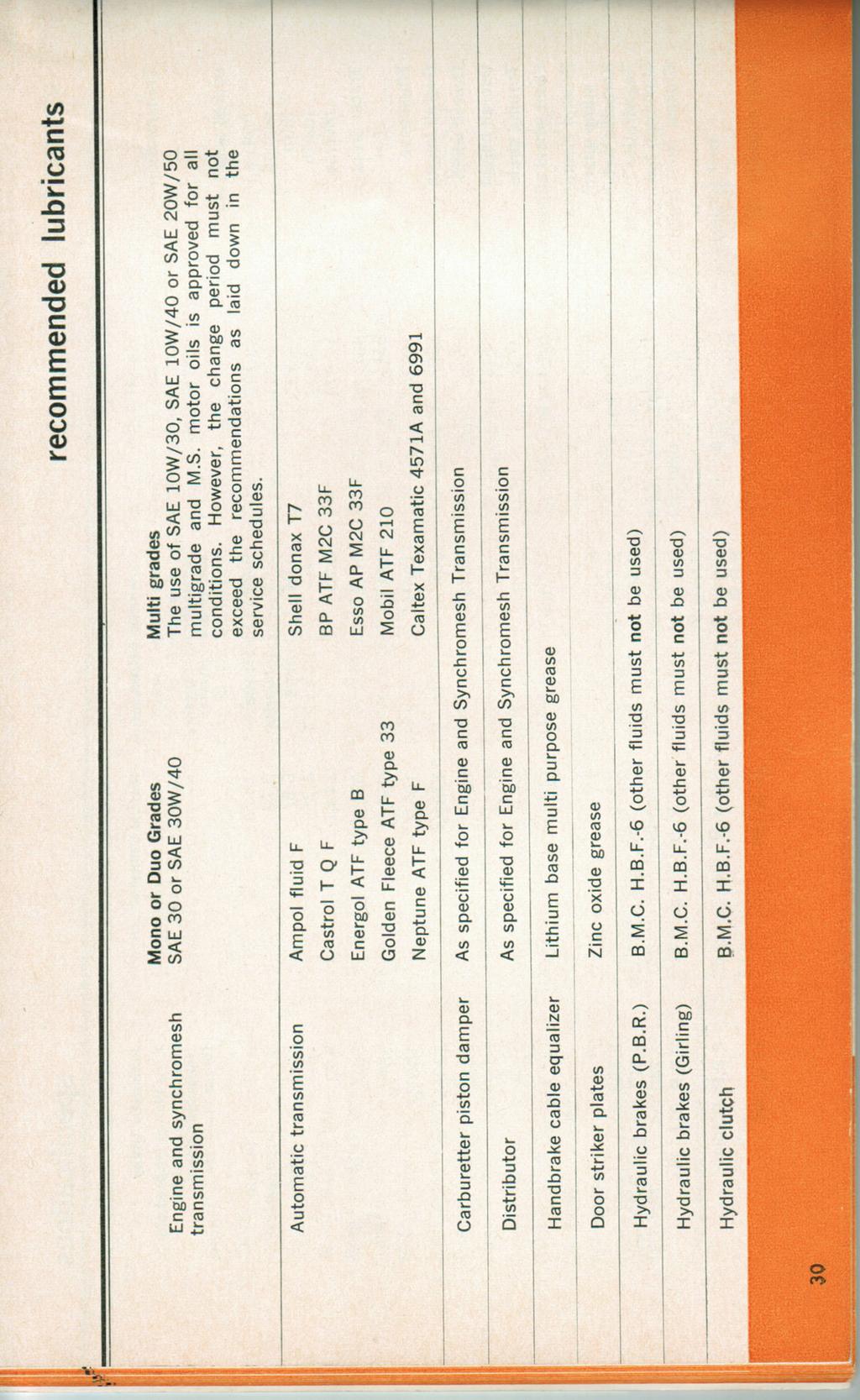
26 Engine oil level (automatic and synchromesh transmission models) Maintaining the correct engine oil level is very important. Too much oi l cause frothing and ecessive splash which the piston rings cannot Correct readings cannot be assumed immediately after stopping the vehic such as when purchasing petrol at a service station. In these circumstance oil will still be suspended in the upper regions of the hot engine. Dipstick readings must be taken on level ground. Always replace the dipstick with the word oil reading from the front of the car Oil changing The engine oil should be changed every 3000 miles, or three months, which ever is the earlier, under normal conditions. More arduous operation such a stop'start running, slow heavy traffic or in very dusty atmospheres demand more frequent oil changes. The advice of the 8.M.C. dealer should be taken on this aspect. Additional additives to the engine oil are not normally necessary or desirable. Included in passport service each 3000 miles or three months. Automatic transmission oil level The transmission must be at normal running temperature. To check trans mission oil level, select 'P' and with engine still idling withdraw dipstick, wipe clean with non fluffy cloth, insert and withdraw immediately. The difference between the high and low marks is 1 imp. pint. Do not overfill. Use only approved automatic transmission fluid (refer "recommended lubricants" section) and observe scrupulous cleanliness. Transmission oil is separate from engine oil. Additional additives must not be used under any circumstances in t he automatic transmission oil. It is not necessary to drain the automatic transmission at periodic intervals. Checking included in passport service each 3000 miles or three months. 24


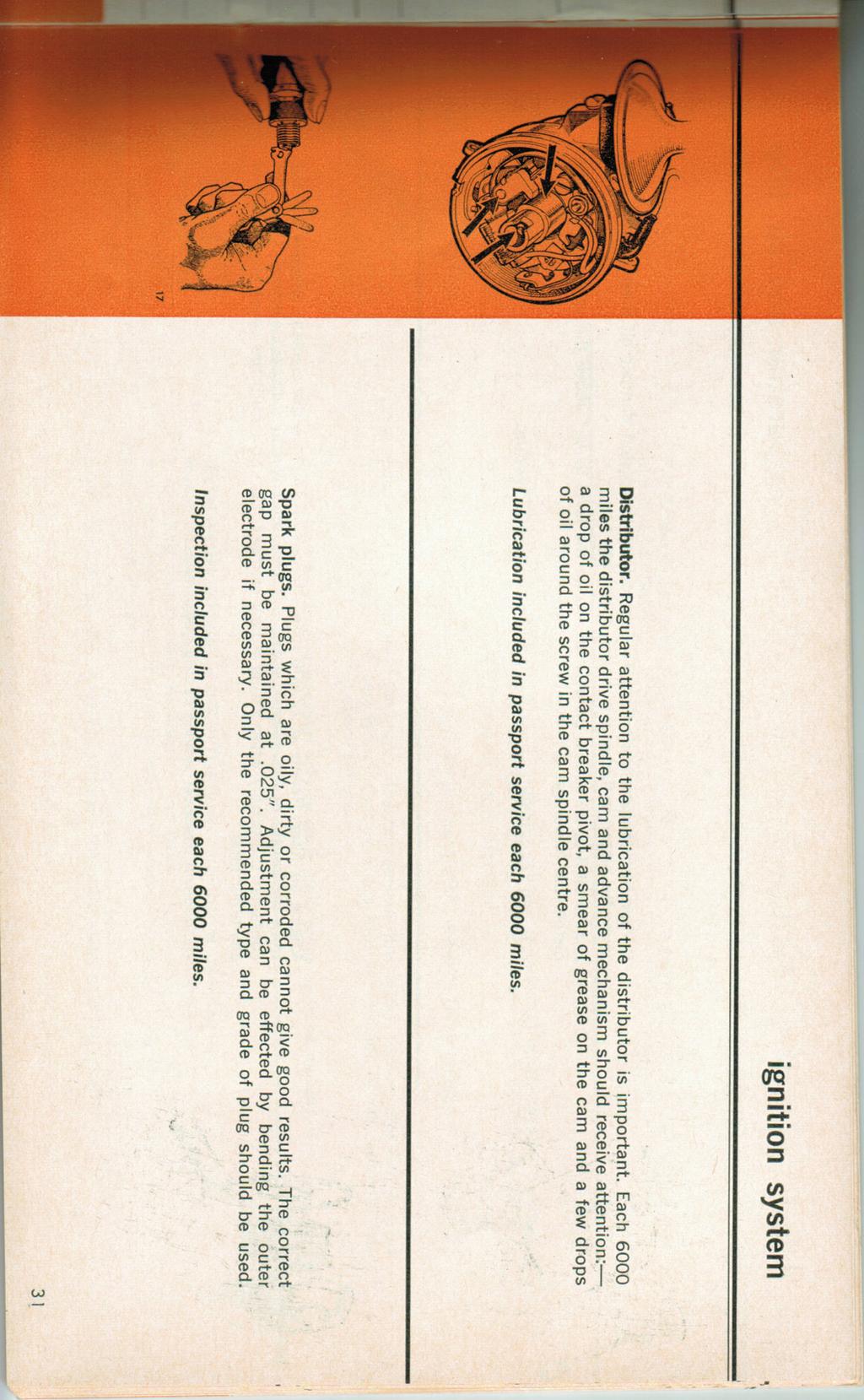
27 lubrication Engine oil filler cap and filter. The filler cap is fitted with an air filter for the sealed breathing system of the power unit. To replace, unscrew the cap and detach the plastic retainer from around the rocker cover neck. The cap assembly should be replaced at 12,000 mile intervals. Included in passport service each 12,000 miles. Oil filter. The e'xternal oil filter element is renewed by unscrewing the canister. When replacing use only hand pressure, renew at 6000 mile intervals. Included in passport service each 6000 miles. Handbrake linkage (Girling system). Regular lubrication of the rear handbrake equalizer pivot is important and should be carried out at 3000 mile intervals. Included in passport service each 3000 miles or three months. Handbrake linkage (P.B.R. system). Lubrication is not necessary on vehicles fitted with this system. 25 "J.9


28 cooling syste A specially designed pressurized cooling system incorporating an epan tank is used on this vehicle. Regular topping up is not normally necessary but as a precaution it is mended that water levels be inspected frequently. Owing to the generated in the system under normal running conditions the radiator cap must not be removed unless the system is cold. To remove the cap t u anticlockwise until a stop is felt. Lift the safety spring catch clear a continue turning to release fully. Water levels. The radiator water should be level with the bottom of the fi ll r neck and the epansion tank should be approimately half full. Should it be necessary to check the water level when the system is hot it i essential that the epansion tank cap be removed slowly before any attem pt is made to remove the radiator cap. Failure to observe this procedure cou ld result in serious injury from scalding. Included in passport service each 3000 miles or three months. Draining the cooling system The cylinder block and radiator bottom tank drain plugs are shown in the diagrams. When draining the system, the radiator cap should be removed. ThiS procedure does not drain the heater or epansion tank. Use of anti freeze solution. Only anti freeze of the ethylene glycol type is suitable. Fluids conforming to specification BS3151 or BS3152 should be used. For vehicles operating in conditions where prevailing temperatures are below freezing an anti freeze solution should be used. Before adding anti freeze solution, the cooling system should be drained and flushed clean. When refilling the system add the anti freeze solution first.


 6 1,4 pints 7 % pints")


29 capacities Engine lubricating oil S without filter Manual gearbo models with filter... l S without filter Automatic gearbo models l with filter pints (add as required) 13 pints (add as required) 6 1,4 pints 7 % pints Engine oil filter pints automatic transmission fluid Initial fill 13 pints Fuel tank Saloon Utility.. lot gals. 13 gals. Cooling system With heater (saloon) Without heater (utility) pints 8Vz pints 27
 3.50 in. (88.90 mm) 1798 cc (109.75 cu.in.) 8.6:1 16 87 @ 5,300 rpm 101 Ib.ft. @ 2,200 rpm 1 3 4 2 10 BTDC @ 500 rpm.014\"-.016\" Champion N9Y.")
 20 SL 550 rpm ma. in 'N'.015\" cold 165 14 radial ply tubeless 4 cyl. o.h.v. 18YF/Ta/H 3.16 in. (80.26 mm) 3.50 in.")
30 specifications Manual Saloon Automatic Saloon Manual Utility Automatic Utility Engine - type ident ification Bore Stroke Cubic capacity Compression ratio R.A.C. h.p. rating Brake horse power Torque Firing order Ignition timing Contact breaker gap Spark plug Spark plug gap Carburetter type Carburetter needle Idle speed Valve rocker clearance Tyre size 4 cyl. o.h.v. 18YD/Ta/H 3.16 in. (80.26 mm) 3.50 in. (88.90 mm) 1798 cc ( cu.in.) 8.6:1 16 5,300 rpm 101 2,200 rpm rpm.014"-.016" Champion N9Y.025" SU HS 6 (1 %") 20 SL 500 rpm.015" cold radial ply tubeless 4 cyl. o.h.v. 18YE/Rc/H 3.16 in. (80.26 mm) 3.50 in. (88.90 mm) 1798 cc ( cu.in.) 8.6:1 16 5,300 rpm 101 2,200 rpm rpm.014"-.016" Champion N9Y.025" SU HS 6 (1 %") 20 SL 550 rpm ma. in 'N'.015" cold radial ply tubeless 4 cyl. o.h.v. 18YF/Ta/H 3.16 in. (80.26 mm) 3.50 in. (88.90 mm) 1798 cc ( cu.in.) 8.6:1 16 5,300 rpm 101 2,200 rpm rpm.014"-.016" Cham pion N9Y.025" SU HS 6 (1 %") 20 SL 500 rpm.015" cold tubeless (6 ply) 4 cyl. o.h.v. 18YE/Rc/H 3.16 in. (80.26 mm) 3.50 in. (88.90 mm) 1798 cc ( cu.in.) 8.6:1 16 5,300 rpm 101 2,200 rpm rpm.014"-.016" Champion N9Y.025" SU HS 6 (1%") 20 SL 550 rpm ma. in ' N'.015" cold tubeless (6 ply) Tyre pressures (a ll cond it ions) front rear 28 Ib./sq.in. 22 Ib./sq.in. 28 Ib./sq.in. 22 Ib./sq.in. 28 Ib./sq.in. 28 Ib./sq.in. 28 Ib./sq.in. 28 Ib./sq.in. 28, - -., -i'... IrIlIb ;.-:~m. ~.. r
 Kerbside weight Registration weight Maimum towing weight")


31 -_. specifications Transmission - overall gear ratios: first second third fourth reverse Track: front rear Wheelbase Overall length Overall width Overall height Turning circle type Front wheel alignment Ground clearance (at sump guard) Kerbside weight Registration weight Maimum towing weight Brakes: front (disc) Load capacity rear (drum) Manual Saloon 4 speeds and reversesynchromesh on all forward gears h" 55 1 h" 106'1s" 166" 661's" 56%" 37 ft. % " toe in 6 1;2" 2,610 Ibs. 2,549Ibs. 2,240Ibs. P.B.R. 9 1 /4" dia. Girling 9%2" Girling 9" dia. P.B.R. 9" dia. Automatic Saloon Borg Warner 3 speed and reverseautomatic transmission with torque converter h" 55 1 h" 106%" 166" 661's" 56 1 /4 " 37 ft. } %" toe in torque converter range 1:1 to 2:1 6" 2,624Ibs. 2,562Ibs. 2,240Ibs. P.B.R. 9 1 /4" dia. Girling 9 9 / 32 " Girling 9" dia. P.B.R. 9" dia. Manual Utility 4 speeds and reversesynchromesh on all forward gears ;2 " / 32 " 106%" 173%" 66%" 57 3 /4" 37 ft. l/s" toe in 7" 2,598Ibs. 2,517 Ibs. gvw 3,800 Ibs. 2,240Ibs. P.B.R. 9 1 /4" dia. P.B.R. 9" dia. 10% cwt. Automatic Utility Borg Warner 3 speed and reverse-automatic transmission with torque converter h " / 32 " 106% " 173%" 66%" } 57%" 37 ft. lis " toe in torque converter range 1:1 to 2:1 7" 2,598Ibs. 2,521 Ibs. gvw 3,800 I1JS. 2,240Ibs. P.B.R. 9 1 /4" dia. P.B.R. 9" dia. 10% cwt. 29
32
33


34 carburetter and air filter Carburetter damper lubrication. Failure to keep the piston damper oil level correct may cause the piston to flutter and reduce acceleration. Engine oil SAE 20 should be used to top up the level to %" above the top of the hollow piston rod. Never use a heavy bodied lubricant. Included in passport service each 3000 miles or three months. Engine air filter. Renew at 12,000 mile intervals. To replace the element unscrew the nut from the centre of the cleaner cover, withdraw the cover and discard element. Clean the container thoroughly when fitting a new element. Do not disturb the cover or element at any other time. Included in passport service each 12,000 miles. 32 o _0 --~-~ ~- - - ~ I....' ~ 0

. The master cylinder is mounted on the engine bulkhead.")
.")
. The master cylinder is mounted on the engine bulkhead.")
35 33 hydraulic brakes and clutch P.B.R. and Girling systems. The braking system may be either of Girling or P.B.R. manufac ture and can be readily identified by observing the manufacturers name on the cap of the master cylinders as indicated by the illustrations. Brake master cylinder (Girling). The master cylinder is mounted on the engine bulkhead. Correct fluid level is indicated by a line B on the outside of the reservoir. Use only fluid to HBF 6 specifications. Strict cleanliness is essential. Level check included in passport service each 3000 miles or three months. Clutch master cylinder (Girling). Mounted beside the brake master cylinder on the bulkhead. Correct fluid level is indicated by a line A on the outside of the reservoir. Use only fluid to B.M.C. HBF 6 specifications. Level check included in passport service each 3000 miles or three months. Brake master cylinder (P.B.R.). The master cylinder is mounted on the engine bulkhead. Maimum and minimum levels are indicated on the 2 transparent fluid reservoirs, thus eliminating unnecessary removal of the caps. Should the level of fluid fall below the minimum line, an immediate investigation should be made. Only fluid to B.M.C. HBF-6 specification should be used. Level check included in passport service each 3000 miles or three months.


 adjustment. Normal adjustment is automatically obtained when the brakes are applied in everyday reversing.")
36 hydraulic brakes and clutch Front brake pads. Wear on the disc brake pads is automatically compensated during normal braking operations. The pads must not be allowed to wear below a minimum thickness of i1r" of the friction facing material before being renewed. Disc brake pads should be eamined every 3000 miles. Included in passport service each 3000 miles. Rear brakes (Girling type) adjustment. Ecessive brake pedal travel is an indication that the rear brake shoes require adjusting. To adjust, release the handbrake and turn the epander in a clockwise direction until the drum locks and then back off until the drum is just free to rotate without rubbing. Included in passport service each 3000 miles or three months. Inspection of linings. The drums should be removed for inspection of linings and wheel cylinders at 12,000 mile intervals. Included in passport service each 12,000 miles. Rear brakes (P.B.R. type) adjustment. Normal adjustment is automatically obtained when the brakes are applied in everyday reversing. Ecessive handbrake travel will indicate the need for adjustment. To adjust, apply the brakes several times whilst reversing. Included in passport service each 3000 miles or three months. Inspection of linings. The drums should be removed for inspection of linings and wheel cylinders at 12,000 mile intervals. Included in passport service each 3000 miles or three months. 34
. The filter should be renewed at 24,000 mile intervals.")


.")


37 hydraulic brakes and clutch Brake servo air filter (Girling system). The filter should be renewed at 24,000 mile intervals. To remove, first clean filter area and release the centre fiing screw. Remove the cover and element. Wipe clean the filter seat and cover. Fit a new element followed by the cover and retaining screw. Included in passport service at appropriate mileage. Brake servo filter (P.B.R. system). This filter requires to be cleaned at 12,000 mile intervals. It is recommended that this operation be entrusted to a B.M.C. dealer. - ~ Included in passport service each 12,000 miles. P.B.R. dual circuit braking system. This system provides two independent braking systems for front and rear brakes respectively. In the unlikely event of a failure occurring in either f the brake circuits the remainin circuit will rovide an effective emergency brake. _ The veh icle should not, however, be allowed to continue to run with either circuit out of operation; the failed system should be rectified immediately. 35


38 hydraulic brakes and clutch Preventive maintenance In addition to the recommended periodical inspection of brake components, it is advisable as the car ages and as a precaution against the effects of wear and deterioration, to make a more searching inspection and renew parts as necessary. It is recommended that: 1. Disc brake pads, drum brake linings, hoses, and pipes should be eamined at intervals no greater than those laid down in the maintenance service schedules. 2. Brake fluids should be changed completely every 18 months or 24,000 miles, whichever is the sooner. 3. All fluid seals in the hydraulic system and all fleible hoses should be eamined and renewed if necessary every 3 years or 40,000 miles, whichever is the sooner. At the same time the working surface of the pistons and of bores of the master cylinder, wheel cylinders, and other slave cylinders should be eamined and new parts fitted where necessary. Care must be taken always to observe the following points: (a) At all times use the recommended brake fluid. (b) Never leave fluid in unsealed containers. It absorbs moisture quickly and this can be dangerous. (c) Fluid drained from the system or used for bleeding is best discarded. (d) The necessity for absolute cleanliness throughout cannot be over emphasized. BMC SERVICE 36


39 3 suspension The suspension system employed on this vehicle is of the * hydrolastic type. All work connected with the system must be entrusted to an authorised B.M.C. dealer. Under no circumstances must the system be tampered with, and the valves located behind the engine as shown in the illustration must not be unscrewed. The suspension system works under hydraulic pressure, and it is important that only the correct servicing equipment be used when releasing the valves. In the unlikely event of the * hydrolastic suspension system suffering damage and the fluid being lost, the suspension arms on the damaged side of the vehicle will contact the bump rubbers at both front and rear. In this condition the car may be driven with complete safety up to 30 mph over surfaced roads to the nearest authorised B.M.C. dealer. registered trade mark


40 f battery, Dirt and moisture should not be allowed to accumulate on the top of the battery. Moisture removed from the top of the battery usually contains acid and should be treated with caution. Cloths used for cleaning must not come in contact with cloth ing, fabric, skin or the vehicle's pa intwork. The battery normally generates a gas which is inflam mabie. Under no circumstances m ust the battery be eamined with an open flame. Fluid level. The battery fluid level is maintained by removal of the plastic filler plugs and adding distilled water until the perforated guard over the cell separators is just covered. The battery must not be overfilled. The need for addition of distilled water will vary with vehicle operating conditions and climatic c0nditions. In h<:>t climates water must be added more frequently. Battery terminals. Should be kept clean and tight. Do not hammer on the terminals. Petroleum jelly (not grease) should be smeared around the terminal after it has been connected to the battery to prevent corrosion. This vehicle is equipped with an alternator. To avoid damage to the alternator the tollowing precautions must be observed. The engine must not be operated with the battery cables disconnected- when starting with the aid of a battery booster do not disconnect the vehicle battery terminals. Disconnect both battery terminals before using a fast battery charger. Disconnect one or both battery terminals before carrying out electric welding, mechanical or electrical operations which could ground or "short" alternator or regulator terminals (even momentarily). Negative earth. The battery must be connected with the negative terminal to earth , '.


.")
41 lamps and fuses Headlamp. The head lamps are of the sealed beam type which do not use separate bulbs. In the event of a failure the sealed beam unit is replaced. To replace, unscrew the 2 screws securing the outer bezel. The 3 Phillips head screws (1) should now be removed, to allow removal of the retaining plate. The sealed beam may then be pulled forward and the connector unplugged. Note that screws 2 and 3 should not be disturbed as these are adjustments for headlight aim. Headlight aim is checked in passport service each 6000 miles. Sidelamp bul~s. The plastic lens is secured by 2 screws but It is necessary to loosen the flasher light lens to free the end of the side lamp lens. The bulb has a bayonet type fiing which is turned to permit removal. Be careful not to lose the rubber sealing washers on each screw. Front flasher bul!js. The plastic lens is secured by 3 screws. The bulb has a bayonet type fiing with staggered pins. The bulb is turned to permit removal. Be careful not to lose the rubber sealing washers on each screw. Rear lamp bulbs (saloon). Unclip the snap fastener retaining the boot trim. Peel back the adhesive dust proofing sheet from the top. The lamp holders may now be pulled from their fiings through the access hole in the panel. The stop and tail light bulb is of the twin filament bayonet type, and offset pegs prevent incorrect replacement. The flasher bulb is of the single filament type and may be fitted either way around. 39


42 lamps and fuses Rear lamp bulbs (utility). To gain access to the tail lamps remove the screws securing the access panel at either side of the tray, just forward of the tailgate. The bulb holders complete with bulbs may be pulled out from the lamp back plate. The flashing indicator lamps have single filament bulbs which may be replaced either way around. The tail and stop lamp bulb has a twin filament. The offset peg bayonet fiing ensures correct replacement. Rear number plate bulb (saloon). To remove a bulb, push in and turn the lens to disengage the fiing and then remove the lens. The capless bulb can then be pulled straight from its socket. 22 Rear number plate bulbs (utility). Access to the twin number plate illumination bulbs is gained by removing the centre screw from the lamp cover and turning and removing the bulb from its holder.


43 4 lamps and fuses Warning and panel lamps. The warning lamp and panel lamp bulbs are located in the positions shown. Access to the bulb holders is gained by reaching behind the fascia panel. After removing the push fit holders the bulbs may be withdrawn. Car interior lamp. To remove the plastic cover on the interior light, gently squeeze the sides of the cover together and then withdraw. The festoon type bulb may then be pulled straight from its clips. The light is controlled by a switch on the base of the lamp and also by automatic switches operated by the front doors. Boot interior lamp. This lamp operates when the boot is opened. The plastic lens is held in position by two screws. The festoon type bulb may then be pulled straight from its retaining clips. Note. All lamps and fuses are checked functionally at each passport service.
. This fuse protects the accessories which are connected so that they operate irrespective of whether the ignition is on or off.")
.")

44 lamps and fuses Fuses. 3 fuses (together with 2 spares) are located in a plastic covered holder on the engine side of the bulkhead near the master cylinders. Fuse connection 'Al' and 'A2' (35 amp). This fuse protects the accessories which are connected so that they operate irrespective of whether the ignition is on or off. Fuse connecting 'A3 ' and 'A4' (35 amp). This fuse protects the accessories which are connected so that they operate only when the ignition is switched on (stop lights, windscreen wipers, etc.). Fuse connecting 'A5' and 'A6' (35 amp). The side, tail, and panel lights are protected by this fuse. A blown fuse is indicated by the failure of all the units protected by it, and is confirmed by eamination of the fuse when withdrawn. Spare fuses. Spare fuses are provided, and it is important to use only the correct replace ment. The fusing value is marked on a paper slip inside the glass of the fuse. If the new fuse blows immediately and the cause of the trouble cannot be found, have the equipment eamined by an authorised 8.M.C. dealer. 42


45 lamps and fuses Electrical Connections for Accessories Wiring for driving lamps. The take off point should be from the dip switch terminal which carries the blue lead with white tracer thence through a control switch to the lamp unit which should be earthed. This method of wiring permits the lamps to be operated only on the high beam. Wiring for fog lamps. The take off point should be from the terminal A4 of the fuse bo thence through a double action switch with the first position to the left hand lamp and the second position to the right hand lamp. Both lamp units should be earthed. This method of wiring permits the use of the left hand lamp in the first position of the switch and both lamps with the switch in the second position. Suitable connectors are available from Authorised B.M.C. Dealers. Wiring for trailer lighting. Before fitting additional wiring for caravans or trailers a check should be made to ensure that compulsory safety regulations relating to trailer or caravan lighting are not violated. Trailers must not be connected to eisting flasher equipment without additional overload compensation as the resultant overload will cause an abnormal rate of flashing. Harness connectors for use where a break into the harness is necessary and overload protected relay warn ing lamp assemblies are available from Lucas agents and Authorised B.M.C. Dealers. (Saloon.) To prevent overloading of the day/night direction indicator and stop lamp relay it is essential to tap into the circuit prior to the current passing through this unit. The relay unit is located forward of the access panel in the right hand rear guard. Identification of the wiring and terminals is as follows:- Tail and number plate lamp: Red with green tracer- Terminal WI. Stop lamps: Green with purple tracer-terminal 1. Left hand flasher: Green with red tracer-terminal 2. Ter- Right hand flasher: Green with white tracer - minal3. Earth: Black-Terminal W2. (Utility.) The day/night relay unit is not fitted. The cables should be cut and spliced with suitable fittings at a point inside the right hand rear access panel. The colour coding on both vehicles is identical. 43


46 miscellaneous Fan belt. Tension should be eamined at regular intervals to ensure efficient operation of the alternator. Check that the total deflection of the driving belt does not eceed %" under moderate hand pressure at the midway point of its longest run. To adjust the belt tension slacken off bolts 1 and 2 and retension the adjusting link 2 first. Included in passport service each 6000 miles. Windshield washer reservoir. The plastic reservoir should be filled with clean water. Special anti freeze fluids are available and a miture of one of these with water should be used to prevent freezing in the container and/or the windshield. Do not use radiator anti freeze. Included in passport service each 3000 miles or three months. 44


. Any spots of grease or tar on the bodywork can be removed by using kerosene.")
47 care of body Interior. It is advisable to clean the interior of the car before washing the outside. All loose dust and dirt can be removed with a vacuum cleaner or a small hand broom and dust pan. The seat covering material, although etremely comfortable and durable will still require a certain amount of attention. Ordinary soil is easily removed with warm soapy water applied on a damp cloth. Bad soiling can be removed with a medium stiff nylon brush. Whenever soaps or detergents are used it is important that the upholstery be rinsed clean and wiped dry. Residue of soaps and detergents will have an unsightly appearance, and if left on for long periods can cause deterioration of the upholstery. Eterior. Frequent washing of the car will help to maintain it in a good condition. Once the car is clean it should be dried with a damp chamois leather. It should be noted that drain holes are provided in the bottom of the doors and should be kept open and f ree from build up of dust and foreign matter. In addition to regular maintenance of the eterior of the bod," work, further attention is required to the underside of the vehic:e, when operating in etreme conditions (e.g., continuous driving over unsealed roads through snow and mud, in salt or other mineral areas, etc.). Any spots of grease or tar on the bodywork can be removed by using kerosene. It is a good idea to polish the car occasionally to remove foreign matter, which over a period of time, builds up on the paint and tends to dull its original lustre. Silicone or wa based polishes must be kept off the windscreen as they are difficult to remove and have a detrimental effect on the wiper blades. If this polish is accidentally applied to the windscreen. il can be removed by the use of a mild domestic abrasive. Bright t rim. An occasional rub with a clean soft cloth will remove dust from the chromium' plated parts, alternatively the bright trim can be cleaned very successfully with warm soapy water. If a light polish is necessary use a quality chrome polish but not ordinary metal polish as this contains abrasives which will affect the surface of the plating. Upholstery. Listed be low are a few hints to help you remove common and frequently encountered stains from your upholstery. Lipstick, shoe polish and grease. Remove as much of the stain as possible with a dry rag. Try to avoid spreading the stain, gently wipe the stain with a cloth moistened with methylated spirits. Wash over with warm soapy water. Battery acid, Battery acid may destroy the surface of your fabric or permanently stain it. Household ammonia applied immediately will neutralize the acid and prevent any further deterioration of the surface. Chocolate. Remove ecess chocolate with a spoon, and wipe over with a c loth moistened with methylated spirits t hen wash with warm soapy water. Liquor and fruit stains. Apply very hot water to the stain or mark, dry thoroughly, then wipe over with a clean cloth moistened with methylated spirits. Do not use warm soapy water as this will possibly set the stain. 45


48 passport to service The "Passport to Service" schedules have been formulated by B.M.C. engineering and service departments to ensure complete maintenance protection. passport to service The importance of correct maintenance cannot be too highly emphasised. The use of " Passport to Service" schedules ensures: 1. Fied costs for preventative maintenance. 2. Permanent evidence of proper care and maintenance which will: ensure full application of warranty; Enhance the resale value of the vehicle. It is recommended that the vehicle be entrusted to an authorised B.M.C. dealer, thus taking the advantage of his specialised equipment, factory trained personnel, as well as genuine B.M.C. parts which carry the same warranty as the new vehicle. The schedules constitute the minimum maintenance required to ensure continuous trouble free operation. Should a vehicle be operated under arduous conditions, more frequent servicing could well be desirable. In such cases the B.M.C. dealer should be consulted for advice. Safety check. For owners who cover less than 3000 miles in three months, it is recom mended that an interim safety check be carried out on a three monthly basis. This is primarily intended to protect the owner operating under etreme low mileage conditions, and discretion must be used when the circumstances are between these etremes of time and mileage. Should the owner be in doubt, he should consult the B.M.C. dealer. Spaces for recording safety checks are provided on the subsequent mileage voucher. Current charges. Refer inside back cover. 46


49 ... ~ ~.~U'1'-...,,' ~,_ ~ ~. '~r::-:-l' ~~_~ after sale free service voucher at or before 1000 miles after sale free service This service has been carried out by DEALER TOWN AND STATE The service detailed on the back of this voucher will be carried out free by the authorised BMC dealer from whom the vehicle was purchased. There will be no charge for this service, other than for materials. Should it not be convenient to return the vehicle to the selling dealer he will on req uest authorise the service to be carried out by another BMC dealer by stamping this voucher. The After Sale Free Service should be carried out at or before the completion of the first 1,000 miles. Selling Dealer's Name a nd Address L The service detailed has been carried out to my satisfaction. MILEAGE DATE Sig nat ure of Owner... SIGNATURE Service Carried out by L Date..,... """".""."".".at...,. ""... """miles, Chassis No. Reg, No, """"""".Model"."", """',.,,,.,, "" """." 41


50 after sale free service Check and retension cylinder head and rocker shaft nuts. Change engine oil and clean drain plugs. Eamine drive shaft boots for indications of leaks or damage. Eamine for indications of fluid leakage at all joints, unions, etc. Eamine underside of vehicle for damage, tighten loose bolts and fittings. Lubricate distributor drive spindle, cam and advance mechanism. Check distributor contact points resistance and dwell angle and adjust dwell if necessary. Check ignition timing and adjust if necessary. Eamine fan belt tension and adjust if necessary. Check and top up, if necessary, brake and clutch master cylinders and carburetter piston damper/so Check and top up, if necessary, radiator, epansion tank and windscreen washer reservoir. Check and top up battery cells. Pressure check cooling system for leaks. Check tyres for correct pressures including spare. Check vehicle suspension heights and adjust if necessary. Check toe in/out of front wheels. Adjust if necessary. Check headlight beam setting. Check valve rocker clearances and adjust where necessary. Check electrical system and instruments functionally. BRITISH L.EYLAND BMC SERVICE Eamine and lubricate door hinges, striker plates, bonnet and boot locks, adjust If necessary. Remove ecess lubricant. Road test for irregularities in performance of the following: - engine - suspension - transmission - brakes - steering 48 ~ ~.,... ' ~';"'~~~:JH,:,~~;. ~~_ '\f.

 U) U) \"0 o ~ -o U) (1) ~ < _.")
51 SERVICE MILES Safety Check Service Speedo Dealer Date N EXT PASSPORT SERVICE MILES Safety Check Service MILE MAINTENANCE SERVICE Speedo Dealer Date NEXT PASSPORT SERVICE MILES NEXT PASSPORT SERVICE 9000 MILES NEXT PASSPORT SERVICE 6000 MILES NEXT PASSPORT SERVICE ~ Safety Check Service Safety Check Service Safety Check Service Safety Check MILE MAINTENANCE SERVICE Speedo Dealer Date MILE MAINTENANCE SERVICE Speedo Dealer Date 6000 MILE MAINTENANCE SERVICE Speedo Dealer Date 3000 MILE MAINTENANCE SERVICE "0 Q) U) U) "0 o ~ -o U) (1) ~ < _. n (1) o < c: n ::T (1) ~ U)


52 50 service notes


53 42000 MILES Check Service Speedo Dealer Date N EXT PASSPORT SERVICE MILES Safety Check Service MILE MAINTENANCE SERVICE Speedo Dealer Date NEXT PASSPORT SERVICE MILES NEXT PASSPORT SERVICE MILES NEXT PASSPORT SERVICE MILES NEXT PASSPORT SERVICE MILES Safety Check Service Safety Check Service Safety Check Service Safety Check (J1 Service MILE MAINTENANCE SERVICE Speedo Dealer Date MILE MAINTENANCE SERVICE Speedo Dealer Date MILE MAINTENANCE SERVICE Speedo Dealer Date MILE MAINTENANCE SERVICE Speedo Dealer n::a.to "C III C/'l C/'l "C o ""I: -o C/'l ~ ""I: :5. (") ~ < o s::: (") :::r ~ ""I: C/'l

54 52 service notes

 \"\"I: ~.")
55 66000 MILES Safety Check Service Speedo Dealer Date NEXT PASSPORT SERVICE MILES Safety Check Service MILE MAINTENANCE SERVICE Speedo Dealer Date NEXT PASSPORT SERVICE MILES NEXT PASSPORT SERVICE MILES Safety Check Service Safety Check Service MILE MAINTENANCE SERVICE Speedo Dealer Date MILE MAINTENANCE SERVICE Speedo Dealer Date "'0 Q) C/I C/I "'0 o ""I: --o NEXT PASSPORT SERVICE MILES EXT PASSPORT SERVICE Safety Check Service I,"Service.a.1 r~ Safety Check MILE MAINTENANCE SERVICE Speedo Dealer Date MILE MAINTENANCE SERVICE C/I (1) ""I: ~. (") (1) < o s::: (") ::r (1) ""I: C/I


56 passport to service schedules The vehicle should be serviced at 3000 mile or three monthly intervals, whichever is the earlier. Engine and cooling system. Check and top up, if necessary, radiator and epansion tank Check cooling system for leaks. Check condition of hoses and tension of hose clip ~ Change engine oil. Clean drain plug Fit new oil filter element Fit new oil f iller cap and filter assembly Clean breather control valve o '" o ID o N... Fuel system. Remove carburetter suction chamber and piston, clean, reassemble and top up... Check and top up, if necessa ry, carburetter piston damper.... Check fuel lines and connections for leaks, including condition of hoses Fit new air cleaner element Ignit ion system. Eamine sparking plugs and adjust gap. Renew if required.... Lubricate distributor drive spindle, cam and advance mechan ism and visually eamine contact points. Check contact points resistance and dwell angle. Reset dwell if required.... Transmission and drive shafts. Eamine when hot, automatic transmission oil level, top up if necessary.... Eamine drive shaft couplings and boots for indications of damage, deterioration or leaks C;,eck and top up, if necessary, clutch master cylinder ~ I I ~ I I r---- I I : I I I I I I I ( I I ( I I ( I I I I I ( I I I I I I I I I I I I ".,_. '''' -.~., = fr _, 'V,~-


 Replace brake servo filter (Girling system) each 24,000 miles Electrical system and instruments. Check and tof) up battery cells......... Eamine fan belt condition and tension-adjust if required.")

57 passport to service schedules Steering and suspension. Observe tyre wear and condition including spare Inspect steering and all suspension moving parts for wear or looseness, including h u b'~ ' " Check wheel nuts and retension front hub nuts Check tyres for correct pressures including spare o '" o <D o N... Brake system. Remove brake drums, eamine linings for wear and wheel cylinders for leakage Check and adjust brakes as necessary, including handbrake Check disc brake pads for wear Visually inspect brake lines and hoses for damage, deterioration or leaks Check and top up, if necessary, brake master cylinder Clean brake servo filter (P.B.R. system) Replace brake servo filter (Girling system) each 24,000 miles Electrical system and instruments. Check and tof) up battery cells Eamine fan belt condition and tension-adjust if required.... Check electrical system and instruments functionally including all lights and cha '~iie in(j"i'c~tor :::. Check headlight beam setting Miscellaneous. Lubricate handbrake linkage.... Eamine underside of vehicle for damage and deterioration. Tighten loose bolts and fi'iiings Eamine for leakage at all joints, seals, etc.... Clean, eamine and lubricate door hinges, striker plates, locks and adjust if necessary Top up windshield washer reservoir Check boot and bonnet mechanism and adjust if necessary... Eamine safety belts and anchorages... Eamine windshield wiper blades and check operation'''of windshield washer Road test " Operation to be carried out. NOTE: The dealer will advise on the need for.. o More frequent oil changes. Refer page 24. Preventive maintenance of braking system. Refer page 36. Wheel balancing, alignment or rotation. Refer page 20. 5:

58 BRITISH notes LEYLAND BMC SERVICE 56 Snt lling Print, Sya


. 3000 miles service $5.")
59 passport to service Current charges (issued August, 1968). The prices at which the respective services will be carried out are listed below. These prices are subject to change due to labour cost increases, etc., and such charges will be advised by means of a 8.M.C. service poster displayed by all dealers. Omission of any part of these schedules at the specified mileage intervals may incur epense at later services. Manual and automatic transmission models (car and utility) miles service $ miles service $ ,000 miles service $14.50 Safety check $3.30 Plus the cost of oils, filters and materials used in each instance.

60 PUBLICATION PART No. TPI05A I BMC SERVICE
Light condition and operation Windshield glass condition Wiper blade condition Paint condition and corrosion Fluid leaks Door and hood lock condition
 GENERAL CHECKS Engine Compartment The following should be checked regularly: Engine oil level and condition Transmission fluid level and condition Brake fluid level Clutch fluid level Engine coolant level
QT INSTRUCTION MANUAL
 QT INSTRUCTION MANUAL PLEASE READ BEFORE USE Distributed by Qpod Motor Company Tel: 01404 850545 Fax: 01404 851110 www.qpod.co.uk Contents Pg 3 Servicing and Warranty Pg 4 Serial Numbers / Vehicle Keys
Maintenance GENERAL INFORMATION
 GENERAL INFORMATION Protect the environment We must all play our part in protecting the environment. Correct vehicle usage and disposal of waste cleaning and lubrication materials are significant steps
Part 7 DO IT YOURSELF MAINTENANCE
 Part 7 DO IT YOURSELF MAINTENANCE Chapter 7 2 Engine and Chassis Checking the engine oil level Checking the engine coolant level Checking brake fluid Checking power steering fluid Checking tire pressure
SECTION 8 2 DO IT YOURSELF MAINTENANCE. Chassis
 DO IT YOURSELF MAINTENANCE Chassis SECTION 8 2 Checking the coolant level of the traction motor................ 184 Checking the radiator....................................... 185 Checking brake fluid........................................
Hillman Minx Maintenance Schedule
 Hillman Minx Maintenance Schedule The maintenance schedule for most Series Minxes can be found as a large fold-out sheet, pasted inside the back cover of the Owner's Handbook. Series V and VI have a much
SECTION O LUBRICATION AND MAINTENANCE. Section Description Page No. O.1 MAINTENANCE GENERAL 3 O.2 FREE AFTER SALES SERVICE (300 MILES) 3
 3") SECTION O LUBRICATION AND MAINTENANCE Section Description Page No. O.1 MAINTENANCE GENERAL 3 O.2 FREE AFTER SALES SERVICE (300 MILES) 3 O.3 FREE AFTER SALES SERVICE (1,200 MILES) 4 O.4 'A ' SERVICE 5 O.5
SECTION O LUBRICATION AND MAINTENANCE Section Description Page No. O.1 MAINTENANCE GENERAL 3 O.2 FREE AFTER SALES SERVICE (300 MILES) 3 O.3 FREE AFTER SALES SERVICE (1,200 MILES) 4 O.4 'A ' SERVICE 5 O.5
MG GS Warranty Statement
 MG GS Warranty Statement Warranty Period The warranty period commences on the date of first registration. MG covers your new MG GS for unlimited mileage up to 12 months, and for 80,000 miles between 13
SECTION 7 2 DO IT YOURSELF MAINTENANCE MR2 U. Engine and Chassis
 SECTION 7 2 DO IT YOURSELF MAINTENANCE Engine and Chassis Checking the engine oil level................................. 168 Checking the engine coolant level............................ 169 Checking brake
SECTION 5 MAINTENANCE
 SECTION 5 Maintenance requirements................................ 166 General maintenance..................................... 167 Does your vehicle need repairing?......................... 170 Scheduled
BRAKE SYSTEM Return To Main Table of Contents
 BRAKE SYSTEM Return To Main Table of Contents GENERAL... 2 BRAKE PEDAL... 10 MASTER CYLINDER... 13 BRAKE BOOSTER... 16 BRAKE LINE... 18 PROPORTIONING VALVE... 19 FRONT DISC BRAKE... 20 REAR DRUM BRAKE...
OWNER S HANDBOOK. Publication Part No. LRL
 OWNER S HANDBOOK Publication Part No. LRL 10 02 50 501 Land Rover 2004 Introduction This handbook covers all versions of the Freelander petrol and diesel models and, together with the other books in the
SECTION O. LUBRICATION/MAINTENANCE. Section Description. Page No.
 SECTION O. LUBRICATION/MAINTENANCE. Section Description. Page No. O.1. General Page 2 O.2. Periodic Services Page 2 O.3. Air Horns Lubrication Page 7 O.4. Recommended Lubricants Page 7 O.5. Exhaust Emission
SECTION 6 3 SERVICE PROCEDURES AND SPECIFICATIONS. Chassis
 SECTION 6 3 SERVICE PROCEDURES AND SPECIFICATIONS Chassis Specifications 206 Checking brake fluid 208 Checking power steering fluid 209 Checking tire pressure 210 Rotating tires 211 Checking and replacing
FORD ECOSPORT Quick Reference Guide
 FORD ECOSPORT Quick Reference Guide About This Quick Reference Guide We have created this guide to help you get to know certain features of your vehicle quickly. It only contains basic instructions to
 3 Protecting Your Xedos Vehicle FUEL REQUIREMENTS EMISSION CONTROL SYSTEM BEFORE DRIVING RUNNING-IN ECONOMICAL OPERATION SPECIAL DRIVING CONDITIONS LABEL INFORMATION 3-2 3-2 3-3 3-4 3-4 3-5 3-8 3-1 3-2
SRT OPERATIONS MANUAL
 MAINTENANCE SECTION PAGE # VEHICLE DAILY INSPECTION.......................................1 P.M. INSPECTION #1.................................................3 P.M. INSPECTION #2.................................................6
OPERATIONS MANUAL LEVER CHAIN HOIST
 OPERATIONS MANUAL LEVER CHAIN HOIST IMPORTANT SAFETY INFORMATION Please read, understand and follow all safety information contained in these instructions prior to the use of this hoist. Retain these instructions
Land Rover Warranty INTRODUCTION DATA PROTECTION STATEMENT
 Land Rover Warranty INTRODUCTION Land Rover and your Dealer thank you for buying a new Land Rover vehicle. We want you to feel happy and assured that whether you are driving for business or pleasure -
FORD ECOSPORT Quick Reference Guide
 FORD ECOSPORT Quick Reference Guide About This Quick Reference Guide We have created this guide to help you get to know certain features of your vehicle quickly. It only contains basic instructions to
John Deere. MODEL: 1010 Gasoline Wheel Tractor JD-O-OMT15504
 John Deere MODEL: Gasoline Wheel Tractor THIS IS A MANUAL PRODUCED BY JENSALES INC. WITHOUT THE AUTHORIZATION OF JOHN DEERE OR IT'S SUCCESSORS. JOHN DEERE AND IT'S SUCCESSORS ARE NOT RESPONSIBLE FOR THE
BAYLIFT SERVICE MANUAL
 -PRINT- MARCH 2014 - TABLE OF CONTENTS- INTRODUCTION I. INTRODUCTION T he RICON BayLift Public Use wheelchair lift is intended to provide wheelchair access to public vehicles including buses, school buses,
before serial number 2214
 before serial number 2214 Contents Page Safety Rules... 3 Pre-operational & Safety Inspection... 4 Operating Instructions... 6 Transport... 12 Maintenance & Routine Service... 12 Specifications... 14 SAFETY
3. INSPECTION/ADJUSTMENT
 3 3 INSPECTION/ADJUSTMENT SERVICE INFORMATION -------------------------------------------- 3-1 MAINTENANCE SCHEDULE ---------------------------------------- 3-2 FUEL LINE/FUEL FILTER -------------------------------------------
1200W INVERTER GENERATOR
 1200W INVERTER GENERATOR MODEL NO: IG1200 PART NO: 8877070 OPERATION & MAINTENANCE INSTRUCTIONS LS0117 INTRODUCTION Thank you for purchasing this CLARKE 1200W Inverter Generator. Before attempting to use
301 0 Row Crop. and Standard
 John Deere MODEL: 301 0 Row Crop and Standard THIS IS A MANUAL PRODUCED BY JENSALES INC. WITHOUT THE AUTHORIZATION OF JOHN DEERE OR IT'S SUCCESSORS. JOHN DEERE AND IT'S SUCCESSORS ARE NOT RESPONSIBLE FOR
WARRANTY AND SERVICE BOOKLET
 WARRANTY AND SERVICE BOOKLET MAINTENANCE RECORD AND WARRANTY BOOKLET MAZDA S NEW VEHICLE WARRANTY Thank you for purchasing a Mazda Vehicle. Our goods come with guarantees that cannot be excluded under
Fluid level checks ENGINE OIL CHECK
 Fluid level checks ENGINE OIL CHECK Check the engine oil weekly. If any significant or sudden drop in oil level is noted, seek qualified assistance. If the message ENGINE OIL PRESSURE LOW is displayed,
SECTION 4 IN CASE OF AN EMERGENCY L/C 100_U
 IN CASE OF AN EMERGENCY SECTION 4 If your vehicle will not start................................... 194 If your engine stalls while driving............................. 197 If you cannot increase the engine
Brake Upgrade Kit Fitting Instructions Bonneville America
 WARNING: Always have Triumph approved parts, accessories and conversions fitted by a trained technician of an authorised Triumph Dealer. The fitment of parts, accessories and conversions by a technician
SECTION 1 7 OPERATION OF INSTRUMENTS AND CONTROLS Ignition switch, Transmission and Parking brake
 SECTION 1 7 OPERATION OF INSTRUMENTS AND CONTROLS Ignition switch, Transmission and Parking brake Ignition switch.............................................. 114 Automatic transmission.....................................
Fitting Instruction for EZI-GRIP Bike Rack
 Fitting Instruction for EZI-GRIP Bike Rack Congratulations on purchasing Ezi-Grip to carry your valued bicycles. We are sure you will get many years of enjoyable use from your Ezi-Grip Bike Rack. These
Service precautions. Emission control system maintenance. Maintenance
 Maintenance Service precautions Vehicle maintenance is an important yet frequently neglected item. Proper maintenance will aid in retaining the level of performance that has been engineered into your Mitsubishi
TC Series Cooling Systems
 TC Series Cooling Systems Table of Contents Table of Contents...1 List of Figures...1 Safety...2 Introduction...2 General Specifications...2 Types of Coolant...2 Routine Maintenance...2 Surge Tank Coolant
SECTION G HUBS, WHEELS AND TYRES. Section Description Page G.1 GENERAL DESCRIPTION 3 G.2 FRONT HUBS 3 G.3 FRONT HUBS - REMOVE AND REPLACE 4
 SECTION G HUBS, WHEELS AND TYRES Section Description Page G.1 GENERAL DESCRIPTION 3 G.2 FRONT HUBS 3 G.3 FRONT HUBS - REMOVE AND REPLACE 4 G.4 REAR HUBS - REMOVE AND REPLACE 5 G.5 WHEELS 6 G.6 TYRES 6
SECTION 6 3 SERVICE PROCEDURES AND SPECIFICATIONS. Chassis
 SERVICE PROCEDURES AND SPECIFICATIONS Chassis SECTION 6 3 Specifications........................................... 208 Checking brake fluid...................................... 210 Checking power steering
ROUSH FUEL SYSTEM UPGRADE CURRENT FORD MUSTANG 5.0L
 ROUSH FUEL SYSTEM UPGRADE 2011- CURRENT FORD MUSTANG 5.0L P/N: 421602 (1313-FPVRKIT) Installation Instructions Before installing your ROUSH Performance Product(s), read through the entire installation
TFP200 FLOOR PLANER OPERATION & MAINTENANCE
 TFP200 FLOOR PLANER OPERATION & MAINTENANCE CS Unitec, Inc. 22 Harbor Avenue, Norwalk, CT 06850 Phone: 203-853-9522 Toll-free: 800-700-5919 Email: info@csunitec.com CS Unitec, Inc. 22 Harbor Avenue, Norwalk,
INSPECTION/ADJUSTMENT
 3 3 INSPECTION/ADJUSTMENT SERVICE INFORMATION----------------------------------------------------------------------- 3-1 MAINTENANCE SCHEDULE-------------------------------------------------------------------
Maintenance Schedules - Diesel Engines
 Published: Jun 9, 2005 Maintenance Schedules - Diesel Engines Torque Specifications Description Nm lb-ft Seat frame fixing Torx screws 40 30 Seat belt fixing Torx screws 40 30 Road wheel nuts 140 103 CAUTION:
Service precautions. Emission control system maintenance. Maintenance
 Maintenance Service precautions Vehicle maintenance is an important yet frequently neglected item. Proper maintenance will aid in retaining the level of performance that has been engineered into your Mitsubishi
Part 1 OPERATION OF INSTRUMENTS AND CONTROLS
 Part 1 OPERATION OF INSTRUMENTS AND CONTROLS Chapter 1-6 Ignition switch, Transmission and Parking brake Ignition switch with steering lock Automatic transmission Manual transmission Four-wheel drive system
Maintenance Schedules - Diesel Engines
 Page 1 of 12 Published: Nov 20, 2008 Maintenance Schedules - Diesel Engines Description Nm lb-ft Seat frame fixing Torx screws 40 30 Seat belt fixing Torx screws 40 30 Road wheel nuts 140 103 M12 tie rod
Brushcutters. Bent Shaft Brushcutter. Straight Shaft Brushcutter BCS260 BCB260
 Brushcutters BCB260 Bent Shaft Brushcutter BCS260 Straight Shaft Brushcutter Please read this instruction manual carefully before operating your new Sanli Brushcutter. Congratulations on choosing a Sanli
Wood Chipper Model C550M Operator's Manual
 Wood Chipper Model C550M Operator's Manual THIS MANUAL MUST BE READ AND UNDERSTOOD BEFORE ANYONE OPERATES THIS MACHINE! Manual# 990023 Revised 01/2010 YOU MUST FILL OUT YOUR WARRANTY REGISTRATION TO ACTIVATE
MODELS 1324 & 1624 & 1824
 THE MODELS 1324 & 1624 & 1824 HYDRAULIC TRENCHERS CONGRATULATIONS! You are now the proud owner of a BARRETO trencher. Please take a moment of your time to look over the following information. Familiarize
English. Fitting Instructions: Bonneville and Bonneville T100 A , A and A of 9. Parts Supplied:
 English Fitting Instructions: Bonneville and Bonneville T00 A958085, A958086 and A958087 Thank you for choosing this Triumph genuine accessory kit. This accessory kit is the product of Triumph's use of
Accessory Fitting Instructions
 Accessory Fitting Instructions Kit Number Models Affected A9689 Thruxton 00 A96808 Thruxton 00 R Low Handlebar Kit Front Fairing Kit Kit Number Models Affected A97080 Thruxton 00 A97084 Thruxton 00 R Note:
Towing and Road Service Guide For The Lexus CT200h. Quality and Education Services AAA Automotive 1000 AAA Drive Heathrow, FL 32746
 Towing and Road Service Guide For The Lexus CT200h Quality and Education Services AAA Automotive 1000 AAA Drive Heathrow, FL 32746 January 4 th, 2011 1 Index General Vehicle Information Major Component
PREMIER, MARINE, & STANDARD
 INSTA LLATION INSTRUCTION AND SERVICE MANUAL I TITAN 12" x 2" BRAKES FREE BACKING. UNI-SERVO. DUO-SERVO PREMIER, MARINE, & STANDARD Limited Warranty TITAN Inc. ("TITAN') warrants its products to be free
JUMPSTART MODEL NO: JS900/JS910 OPERATING & MAINTENANCE INSTRUCTIONS PART NO: & GC10/16
 JUMPSTART MODEL NO: JS900/JS910 PART NO: 6240010 & 6240020 OPERATING & MAINTENANCE INSTRUCTIONS GC10/16 INTRODUCTION Thank you for purchasing this CLARKE Jump-start. Before attempting to use this product,
Reach ins, Freeezers & Refrigerators Installation & Operation Manual
 Reach ins, Freeezers & Refrigerators Installation & Operation Manual BSR23 BSF23 BSR49 BSF49 BSR72 BSF72 IMPORTANT SAFETY INSTRUCTIONS (SAVE THESE INSTRUCTIONS) Visit us on the web at www.blueairinc.com
CAB #11606 FOR John Deere X500, X520, X530, X534, X540
 CAB #11606 FOR John Deere X500, X520, X530, X534, X540 ASSEMBLY INSTRUCTIONS PARTS LIST IMPORTANT READ THIS MANUAL CAREFULLY AND KEEP FOR FUTURE REFERENCE CAUTION! REMOVE THE VINYL PANELS FOR TRANSPORT
SECTION 6 3 SERVICE PROCEDURES AND SPECIFICATIONS. Chassis
 SERVICE PROCEDURES AND SPECIFICATIONS Chassis SECTION 6 3 Specifications........................................... 204 Checking brake fluid...................................... 206 Checking brake pedal
ATV-320 R OWNER S MANUAL
 ATV-320 R OWNER S MANUAL FOREWORD May we, the manufacturer, take this opportunity to thank you for choosing our ATV to serve you. This Owner s Manual is prepared for you to properly operate in safety.
Lighting GENERAL INFORMATION. Daytime running lamps. Condensation. Stop lamps. Halogen headlamps. Reversing lamps. Bi-Xenon headlamps
 Lighting GENERAL INFORMATION There are three types of headlamp systems: Halogen high/low beam main lamp with a fill-in high beam halogen lamp alongside. Bi-xenon high/low beam main lamps with fill-in high
Pre-Post Drive Procedures Lesson 1
 Parent In-Car Check-List Pre-Post Drive Procedures Lesson 1 The instructor should print this document and take it along during the In-Car training. This document will serve as both a training guide as
SECTION M. ELECTRICAL. Section Description Page No.
 SECTION M. ELECTRICAL. Section Description Page No. M.1 General Page 2 M.2 Alternator Page 2 M.3 Battery Page 7 M.4 Hazard Warning System Page 7 M.5 Brake Fail Warning System Page 8 M.6 Seat Belt Warning
20 TONNE HYDRAULIC PRESS MODEL NO: CSA20FBT
 20 TONNE HYDRAULIC PRESS MODEL NO: CSA20FBT PART NO: 7614058 OPERATION & MAINTENANCE INSTRUCTIONS WARNING: Read these instructions before using the press GC0516 INTRODUCTION Thank you for purchasing this
MOTORINI GP 50. User s Manual.
 MOTORINI GP 50 User s Manual www.motorini.co.uk Dear user: Thank you for choosing to buy a Motorini GP 50 This manual provides the correct operation and maintenance methods for safe riding and maintaining
Tooling Assistance Center
 Safeguards are designed into this application equipment to protect operators and maintenance personnel from most hazards during equipment operation. However, certain safety precautions must be taken by
SECTION 4A HYDRAULIC BRAKES
 SECTION 4A HYDRAULIC BRAKES CAUTION: Disconnect the negative battery cable before removing or installing any electrical unit or when a tool or equipment could easily come in contact with exposed electrical
SECTION 1-6 OPERATION OF INSTRUMENTS AND CONTROLS 05 HIGHLANDER_U (L/O 0409) Gauges, Meters and Service reminder indicators
 Gauges, Meters and Service reminder indicators") SECTION 1-6 OPERATION OF INSTRUMENTS AND CONTROLS Gauges, Meters and Service reminder indicators Fuel gauge................................................ 132 Engine coolant temperature gauge...........................
SECTION 1-6 OPERATION OF INSTRUMENTS AND CONTROLS Gauges, Meters and Service reminder indicators Fuel gauge................................................ 132 Engine coolant temperature gauge...........................
Safety Precautions. If a vehicle fire occurs, extinguish it with a Class D powder-type fire extinguisher.
 Safety Precautions Your Toyota Prius has both high-voltage DC and AC systems as well as a 12-volt system. Both DC and AC high voltage are very dangerous and can cause personal injury, severe burns, electric
Installation and Set Up Instructions
 SL SLIDING GATE MOTOR KIT Solar Powered and 12V Low Voltage Installation and Set Up Instructions Unit 27 / 49 Corporate Boulevard Bayswater Vic 3153 Phone 1800 111 930 Email info@gforceautogates.com.au
HOW - TO EMISSION CONTROL BASICS EMISSION CONTROL BASICS
 HOW - TO EMISSION CONTROL BASICS EMISSION CONTROL BASICS Tool And Material Checklist Bore Brush Thermometer Portable Vacuum Pump Screwdriver Combination Wrench Set 3/8 Drive Socket Set Tachometer Rag Service
500kg TELESCOPIC TRANSMISSION LIFTER
 Product Code: 2056T PRODUCT CODE: 2056T 500kg TELESCOPIC TRANSMISSION LIFTER Safe Working Capacity 500kg Base Dimension 540 x 570 mm Minimum Height 1175mm Maximum Height 1900mm Made in China to TQB Brands
MTD OHV Series FORM NO B. jqa=mêççìåíë=^âíáéåöéëéääëåü~ñí= =p~~êäêωåâéå= =déêã~åó
 MTD OHV Series J15 FORM NO. 769-08890B jqa=mêççìåíë=^âíáéåöéëéääëåü~ñí= =p~~êäêωåâéå= =déêã~åó 4 11 19 27 35 43 51 58 65 72 79 87 96 104 112 119 126 134 141 148 155 162 171 179 188 197 206 213 221
SECTION 6 3 SERVICE PROCEDURES AND SPECIFICATIONS. Chassis
 SERVICE PROCEDURES AND SPECIFICATIONS Chassis SECTION 6 3 Specifications........................................... 178 Checking clutch pedal freeplay............................ 180 Checking brake and
RedGum GP160 Splitter. Owner s Manual
 RedGum GP160 Splitter Owner s Manual Product Description & Intended Purpose: This Log Splitter / Wood Splitter is an outdoor product that splits wood logs for use as fuel in a fireplace or a woodstove.
Towing and Road Service Guide For The 2010 Lexus HS250H. Quality and Education Services AAA Automotive 1000 AAA Drive Heathrow, FL 32746
 Towing and Road Service Guide For The 2010 Lexus HS250H Quality and Education Services AAA Automotive 1000 AAA Drive Heathrow, FL 32746 October 7, 2009 Index General Vehicle Information Major Component
Car Battery Charger Instructions for Use
 BATTERY CHARGER 12Volt 4Amp FOR INDOOR USE ONLY Power Details: Input: 230-240Vac; 50Hz; 52W Output: 12V DC; 2.8A Maximum Charge Rate: 4A RMS Read these instructions before operating this car battery charger
Property of American Airlines
 MA Tow Tractor Section 2 SECTION 2: OPERATION A. CONTROLS, INSTRUMENTS AND SWITCHES The tractor controls and instruments include a headlight switch, ignition switch, hour meter, ammeter (if equipped),
Headlamp Assembly. Headlamp Bulb Low Beam H4. Headlamp Bulb High Beam H7 REMOVAL AND INSTALLATION Exterior Lighting
 417-01-52 Exterior Lighting 417-01-52 REMOVAL AND INSTALLATION Headlamp Assembly 3. Remove the rubber boot from the lamp back face. WARNING: Bulbs become hot to touch and can cause burns if not allowed
ATV-320 S/U ATV-320SD S/U OWNER S MANUAL V
 ATV-320 S/U ATV-320SD S/U OWNER S MANUAL V1.0 2014.03.01 0 FOREWORD May we, the manufacturer, take this opportunity to thank you for choosing our ATV to serve you. This Owner s Manual is prepared for you
PRODUCT USE INFORMATION
 9RC61000 Jeep YJ Body Lift Thank you for choosing Rough Country for all your suspension needs. This body lift fits both manual and Automatic equipped vehicles!!! Refer to last page of this Instruction
CUSTOM CARRIERS. Crane Carrier Company Standard Warranty
 CUSTOM CARRIERS Crane Carrier Company Standard Warranty CRANE CARRIER COMPANY ("Manufacturer") warrants each new Crane Carrier sold by it or any of its authorized distributors to be free from defects in
HYDRAULIC BENCH PRESS 50,000kg
 OWNER S MANUAL PRODUCT CODE: 2037T HYDRAULIC BENCH PRESS 50,000kg Working Capacity Height Width Depth Weight 50,000kg 1660mm 1220mm 800mm 236kg Made in China to TQB Brands Pty Ltd specifications WARNING
1100W PORTABLE GENERATOR
 1100W PORTABLE GENERATOR MODEL NO: G1200 PART NO: 8010110 OPERATION & MAINTENANCE INSTRUCTIONS LS0312 INTRODUCTION Thank you for purchasing this CLARKE 1100W Portable Generator. Before attempting to use
1.CONTENTS 1. Contents Control location Before riding Safe riding Driving Use genuine spare parts Use
 1.CONTENTS 1. Contents... 1 2. Control location... 3 3. Before riding... 4 4. Safe riding... 4 5. Driving... 5 6. Use genuine spare parts... 5 7. Use of each component... 6 Gauges... 6 Operation of ignition
Mustang Billet Rear Lower Control Arm Kit
 Mustang Billet Rear Lower Control Arm Kit Part #R06030037 Application: 2005-2009 Ford Mustang Installation Instructions Before installing your ROUSH Performance Product(s), read through the entire installation
Service/Inspection Checklist and Report
 500 Series Loadalls (JCB Dieselmax SA, SB, SC, SD and SF Engines) 500 Series Loadalls (JCB Dieselmax SA, SB, SC, SD and SF Engines) 795270 Dealer Stamp Note: Original copy to customer, Photocopy to distributor.
DeZURIK 2 20" BOS BUTTERFLY VALVES
 2 20" BOS BUTTERFLY VALVES Instruction D10459 October 2013 2-20 BOS Butterfly Valves Instructions These instructions provide information about BOS Butterfly Valves. They are for use by personnel who are
*[BK00050( ALL)05/95]
![*[BK00050( ALL)05/95]](/thumbs/95/123627048.jpg "*[BK00050( ALL)05/95]") General Information 1 Table of Contents General Maintenance Information... 3 What Maintenance Schedule Do You Follow?... 5 Normal Schedule... 6 Severe Duty Schedule... 16 Owner Maintenance Checks... 30
General Information 1 Table of Contents General Maintenance Information... 3 What Maintenance Schedule Do You Follow?... 5 Normal Schedule... 6 Severe Duty Schedule... 16 Owner Maintenance Checks... 30
Wood Chipper Model C551H Operator's Manual
 Wood Chipper Model C551H Operator's Manual THIS MANUAL MUST BE READ AND UNDERSTOOD BEFORE ANYONE OPERATES THIS MACHINE! Manual# 990023 Revised 01/2010 YOU MUST FILL OUT YOUR WARRANTY REGISTRATION TO ACTIVATE
32 quarts Transmission Allison HT 740 Automatic Fluid
 BOOK: Blue Book I SECTION: E-One Engine (SGT) Page 1 of 6 E-ONE CYCLONE TABLE OF CONTENTS SPECIFICATIONS... 2 DAILY CHECKS... 2 SAFETY CHECKS... 3 START ENGINE... 3 STOP ENGINE... 3 EMERGENCY SHUTDOWN
ATV TRACK KIT. Operator s Manual Installation Instructions Service Instructions Replacement Parts List. Effective Date: October, 2012
 p/n 2258-642 ATV TRACK KIT Operator s Manual Installation Instructions Service Instructions Replacement Parts List Track Assembly Kits (p/n 1436-204) Mounting Assembly Kits (p/n 1436-205) 1436-815) Effective
User Manual. MB-6000-UD Rev. 1.03
 User Manual MB-6000-UD Rev. 1.03 Table of Contents I. The Controls II. III. IV. Unit Operations A. Folding the Unit B. Folding the Handlebars C. Unlocking and Unfolding D. Precautions and Starting E. Power
MANUAL SERVICE MANUAL FOR HYDRASTAR HYDRAULIC TRAILER BRAKE ACTUATORS
 MANUAL 440-1008 SERVICE MANUAL FOR HYDRASTAR HYDRAULIC TRAILER BRAKE ACTUATORS THIS DOCUMENT TO BE USED FOR HBA-10, HBA-12, HBA-16, MHBA-10, MHBA-12, MHBA-16 ACTUATORS ECN 04007 Manual 440-1008 Rev E Page
3. INSPECTION/ADJUSTMENT
 3 SERVICE INFORMATION...3-0 FINAL REDUCTION GEAR OIL...3-7 MAINTENANCE SCHEDULE...3-2 DRIVE BELT...3-7 FUEL FILTER...3-3 BRAKE SHOE...3-8 THROTTLE OPERATION...3-3 BRAKE ADJUSTING NUT...3-8 AIR CLEANER...3-4
Motive Power. Network Power. Chargers. Bloc Batteries. Accessories. Service
 The Eternity Technologies range is built using only the highest quality and most efficient production processes at our state-of-the-art manufacturing centre in the UAE. It is this innovation, modern design
Owners Manual MODEL 45 REEL MOWER MODELS & 45148
 Owners Manual MODEL 45 REEL MOWER TM MODELS 45048 & 45148 TM Rover Mowers Limited Model 45 FOREWORD Thank you for buying a Rover Mower. This manual covers the operation and maintenance of the Rover Model
OWNER S MANUAL EPT-55 ! WARNING! HAND PALLET TRUCK
 HAND PALLET TRUCK EPT-55 OWNER S MANUAL! WARNING! DO NOT OPERATE OR SERVICE THIS PRODUCT UNLESS YOU HAVE READ AND FULLY UNDERSTOOD THE ENTIRE CONTENTS OF THIS MANUAL. FAILURE TO DO SO MAY RESULT IN PROPERTY
Indicator and warning lamps. Indicator and warning lamps
 can light up in a variety of combinations and colors. See the table for information on causes and how to react. Note whether a lamp comes on alone or in combination with another. Some lamps can light up
JUMPSTART MODEL NO: JS1000, JS1010 & JS1224 OPERATING & MAINTENANCE INSTRUCTIONS PART NO: , & GC0514
 JUMPSTART MODEL NO: JS1000, JS1010 & JS1224 PART NO: 6240040, 6240035 & 6240045 OPERATING & MAINTENANCE INSTRUCTIONS GC0514 INTRODUCTION Thank you for purchasing this CLARKE Jumpstart. Before attempting
1983 BMW 320i. 1.8L 4-CYL 1983 Engines - 1.8L 4-Cylinder Engines - 1.8L 4-Cylinder
 ENGINE IDENTIFICATION 1.8L 4-CYL 1983 Engines - 1.8L 4-Cylinder For engine repair procedures not covered in this article, see ENGINE OVERHAUL PROCEDURES - GENERAL INFORMATION article in the GENERAL INFORMATION
AIR-COOLED DIESEL GENERATOR OWNERʼS MANUAL. This manual contains important safety information. TDG2500E TDGW7000E TDG7000SE TDG4500E
 AIR-COOLED DIESEL GENERATOR OWNERʼS MANUAL This manual contains important safety information. TDG2500E TDGW7000E TDG7000SE TDG4500E TDG8000-3 TDG7000SE-3 TDG7000E TDG8000E TDGW7000SE TDG7000E3 TDGW8000E
OWNER S MANUAL PRODUCT CODE: 2006T
 Jul-18 Product Code: 2006T OWNER S MANUAL PRODUCT CODE: 2006T HYDRAULIC PIPE BENDER 12,000KG Model Capacity Bending Die No of Attachments 12,000kg 1/2", 3/4", 1", 1-1/4", 1-1/2", 2" 6 Made in China to
Quick Overview WARNING LIGHTS
 Quick Overview WARNING LIGHTS 1. Left-hand direction indicator. 2. Low outside temperature. 3. Glow plug (diesel only). 4. Engine malfunction. 5. Low oil pressure. 6. Battery charge indicator. 7. Front
GROUNDSMASTER. 52 Recycler. for 120 Traction Unit. Model No & UP. Operator s Manual
 FORM NO. 8-980 Rev A GROUNDSMASTER 5 Recycler for 0 Traction Unit Model No. 077 79000 & UP Operator s Manual IMPORTANT: Read this manual carefully. It contains information about your safety and the safety