Manual STE SE 2+1 SPEED 12V & 24V
|
|
|
- Gabriella Parrish
- 5 years ago
- Views:
Transcription


1 Manual STE SE 2+1 SPEED 12V & 24V GENEREL INFORMATION MOUNTING INSTRUCTION EXPLODED VIEW PARTS LIST CONNECTING DIAGRAM WIRE DIMENSION AND FUSE SIZE WORLD WIDE DISTRIBUTION LIST SERIAL NO: PS Part no.: februar 2012
2 2
3 CONGRATULATIONS You have purchased an ANDERSEN high quality winch. This product is a result of many years of development and experience in producing winches for sailboats. This winch gives you a high degree of functionality and many years of safe and easy sail handling. GENERAL INFORMATION PLEASE READ THIS BEFORE INSTALLING YOUR ANDERSEN ELECTRIC WINCH. The electric ANDERSEN winch has some built-in advantages: - Easy to fit on your boat. - Template included. - Special tools included. - Electric unit in turnable in 8 horizontable steps (45 ). - Easy to dismantle. Winch and electric unit can be dismantled separately. - Winch in the usual high ANDERSEN quality, featuring drum, roller bearings etc. of stainless steel. - Always the possibility of manual (2 speed) drive, just by inserting a standard winch handle. No shift-bottom of any kind. - MODULAR POWER SYSTEM : It is possible to exchange the 2+1 SE electric drive unit with a Compact electric drive unit. Mounting Installation: Please follow the mounting instructions. Ensure that each hole in the deck is bedded, including the big hole in the center. IMPORTANT: Be careful not to put bedding compound IN the thread holes in the deck plate. Ensure that the sealing ring (O-ring) on top of the gear unit is placed in its groove. Electric Installation: Please follow the mounting instructions. WARNING: Do not use smaller wire, than recommended in the diagram. This can cause malfunction of the winch and in worst case - FIRE. The wires should always be as short as possible. Normal Use: The electric motor has built-in overload circuit breaker, which breaks the circuit, before the motor gets too hot. After a short period of cooling, depending on temperature under deck, ventilation etc., the winch will be ready for electrical operation again. Meanwhile, if necessary, just insert a standard winch handle, and use the winch as a 2 speed manual winch. We recommend to remove the handle when operated electrically - from a safety point of view. General Service Instructions: The electric drive unit is lubricated sealed and requires no further maintenance. The part on deck is a standard self tailing winch, and needs regular service. We recommend dismantling, cleaning and lubrication once a year. Under extensive use, such as racing, charter or blue water sailing, we recommend to make a further lubrication check during the one year period. We strongly recommend always to use ANDERSEN WINCH GREASE when lubricating your winch. ANDERSEN WINCH GREASE is a high quality silicone/teflon grease. 3
4 MOUNTING INSTRUCTION STE SE 2+1 SPEED FIG.1 FIG.3 FIG.2 Ø24 FIG.4 4

5 IMPORTANT INSTALLATION INFORMATION! It is extremely important that your motor is aligned with your winch. Non-aligned motors will be noisy and gear wear will be accelerated. To insure that your motor is aligned properly the motor flange must be flush with the deck plate and the eightsided nut must fit snugly into the octagon in the deck plate. This can be achieved with the help of the following: Drill the hole through the deck wider that the motor flange. When mounted there must be free space between the deck and the flange. Clean the deck hole before attempting the install the motor so that the motor flange does not catch splinters of fiberglass or wood when being inserted through the deck. Insure that the underside of the deck plate is clean and free from resin, varnish or sealants. Do not use a sealant between the flange and deck plate. An o-ring insures a waterproof connection. Extra waterproofing can be achieved by applying sealant to the top of the deck plate next to the mounting nut after installation. Insure that the locking screw on the mounting nut is not protruding beyond the contact surface before tightening the mounting nut. Tighten the locking screw when the mounting nut is securely in place. FOR GEARUNITS OF THIS TYPE, USE OF LIFTING DEVICE IS RECOMMENDED 5
")
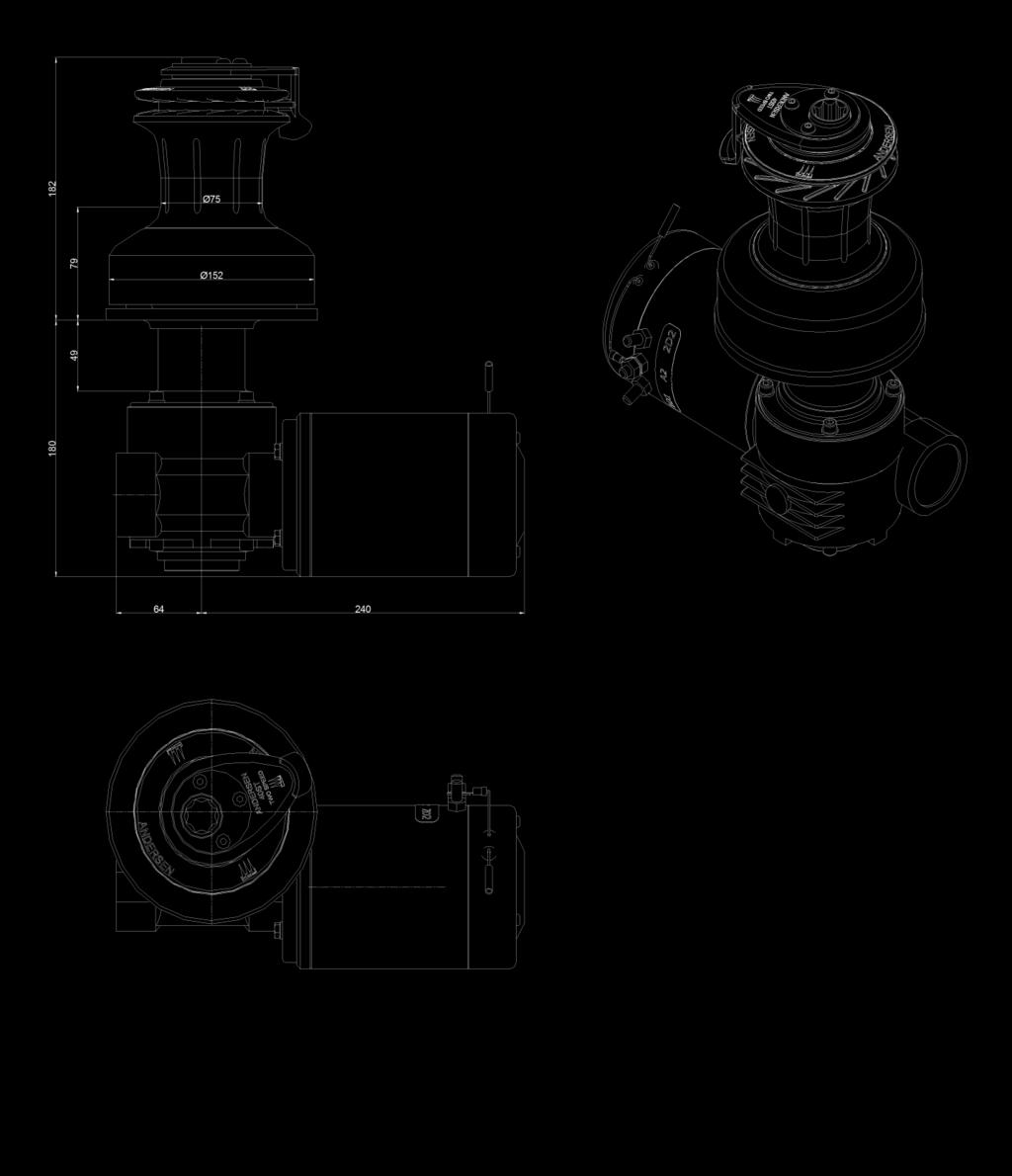
6 INSTALLATION DIMENSIONS 28 STE SE (Non-dimensional accuracy) 6

7 INSTALLATION DIMENSIONS 40 STE SE (Non-dimensional accuracy) 7
")
8 DRILLING TEMPLATE 28 STE SE (Non-dimensional accuracy) 8
")
9 DRILLING TEMPLATE 40 STE SE (Non-dimensional accuracy) 9

10 EXPLODED VIEW STE SE 2+1 SPEED 10
11 PARTS LIST STE SE 2+1 SPEED POS. QTY. DESCRIPTION ART. NO. 1 Gear complete 28STE TYPE Gear complete 40STE TYPE Motor CIMA 1000W 12V STE Motor CIMA 1000W 24V STE Key DIN6885-A-5X5X Gear Unit 28ST SE / 40 ST SE Gear i14 VF Washer DIN125-A4-Ø Screw DIN912-A4-M6x Ratchet gear Key DIN6885-A-8X7X Bushing RD Pawl Arm spring Drive shaft 28STE (OLDER VERSION WITH SPLINE) Drive shaft 40STE (OLDER VERSION WITH SPLINE) Drive shaft 28STE + 40STE Washer Drive shaft housing Bushing RD Sealing ring O-ring RD Deck plate 28STE Deck plate 40STE Screw DIN7991-A4-M6x Center Nut Screw DIN916-A4-M5x Pin Spanner RD Allen key Allen key Template 28STE RD Template 40STE RD Switch labels RD Switch RD Sealing Screw RD Control box 12V Control box 24V Manual 28+40STE SE V
12 CONNECTING DIAGRAM 12V + 24V STE SE 2+1 SPEED WARNING: Don t switch cables (+) with cables (-). Incorrect polarity will permanently damage the control box thus invalidate warranty FUSE - + BATTERI IMPORTANT: Do not use connection 1D1 REMARK: Fuse must be of a slow blow type 12
13 MINIMUM WIRE DIMENSIONS & FUSE SIZES (Not for continuous service) WINCH WIRE LENGTH* 12V. DC 24V. DC WIRE FUSE BAT. CAP. WIRE FUSE BAT. CAP. 28 STE SE 0-3 m / 0-10 ft 35 mm² 125 A 240 Ah 25mm² 76 A 120Ah 3-8 m / ft 50 mm² 160 A 240 Ah 25mm² 100 A 120Ah 40 STE SE 0-3 m / 0-10 ft 35 mm² 125 A 240 Ah 25mm² 76 A 120Ah 3-8 m / ft 50 mm² 160 A 240 Ah 25mm² 100 A 120Ah 46 STE SE 0-3 m / 0-10 ft 50 mm² 160 A 360 Ah 25mm² 100 A 180Ah 3-8 m / ft 70 mm² 200 A 360 Ah 35mm² 125 A 180Ah 52 STE SE 0-3 m / 0-10 ft 50 mm² 160 A 360 Ah 25mm² 100 A 180Ah 3-8 m / ft 70 mm² 200 A 360 Ah 35mm² 125 A 180Ah *) WIRE LENGTH is defined as the distance from battery to switch box + the distance from switch box to motor. IMPORTANT: Fuse must be of a slow blow type. 13
14 14
15 15
16 WORLDWIDE DISTRIBUTION (FOR UPDATED DISTRIBUTOR LIST, PLEASE SEE WARRANTY Refer to our website for our warranty terms and conditions. 16
Manual 46/48 STE SE 2+1 SPEED 12V & 24V
 Manual 46/48 STE SE 12V & 24V GENEREL INFORMATION MOUNTING INSTRUCTION EXPLODED VIEW PARTS LIST CONNECTING DIAGRAM WIRE DIMENSION AND FUSE SIZE WORLD WIDE DISTRIBUTION LIST SERIAL NO: PS Part no.: 710471-9.
Manual 58/62 & 68/72STE SE 2+1 SPEED 12V & 24V
 Manual 58/62 & 68/72STE SE 12V & 24V GENEREL INFORMATION MOUNTING INSTRUCTION EXPLODED VIEW PARTS LIST CONNECTING DIAGRAM WIRE DIMENSION AND FUSE SIZE WORLD WIDE DISTRIBUTION LIST SERIAL NO: PS Part no.:
Manual 52STE SE 2+1 SPEED 12V & 24V
 Manual 52STE SE 12V & 24V GENEREL INFORMATION MOUNTING INSTRUCTION EXPLODED VIEW PARTS LIST CONNECTING DIAGRAM WIRE DIMENSION AND FUSE SIZE WORLD WIDE DISTRIBUTION LIST SERIAL NO: PS CONGRATULATIONS You
Manual 46/48 STE/FS 2+2 SPEED 12V & 24V
 Manual 46/48 STE/FS 2+2 SPEED 12V & 24V GENERAL INFORMATION MOUNTING INSTRUCTIONS IMPORTANT INSTALLATION INFORMATION INSTALLATION DIMENSIONS DRILLING TEMPLATE EXPLODED VIEW PARTS LIST CONNECTING DIAGRAM
Manual 46/48 STE/FS 2+2 SPEED 12V & 24V
 Manual 46/48 STE/FS 2+2 SPEED 12V & 24V GENERAL INFORMATION MOUNTING INSTRUCTIONS EXPLODED VIEW CONNECTING DIAGRAM WIRE DIMENSION AND FUSE SIZE SERIAL NO: PS Part no.: 710446 12-06-2012 CONGRATULATIONS
Manual Hydraulic Unit 110 STH/FS 2+2
 Manual GENERAL INFORMATION GENERAL SERVICE INSTRUCTIONS MOUNTING INSTRUCTION EXPLODED VIEW PARTS LIST DATA FOR HYDRAULIC WINCH WORLD WIDE DISTRIBUTION LIST Serial no.: PS CONGRATULATIONS You have purchased
PRODUCT MANUAL 52ST (V.4.0) 52ST FS (V.4.0.F) RON-WPM ST/52STFS-Rev.3
 52ST FS (V.4.0.F) RON-WPM ST/52STFS-Rev.3") PRODUCT MANUAL 52ST (V.4.0) RON-WPM-710021-52ST/52STFS-Rev.3 52ST (V.4.0) p2 EXPLODED VIEW ITEM. 3 MODEL ST - PART No. 540406 ITEM. 3 MODEL ST FS - PART No. 540411 ITEM. 16 - PART No. 589111 ITEM. 15 -
PRODUCT MANUAL 52ST (V.4.0) RON-WPM-710021-52ST/52STFS-Rev.3 52ST (V.4.0) p2 EXPLODED VIEW ITEM. 3 MODEL ST - PART No. 540406 ITEM. 3 MODEL ST FS - PART No. 540411 ITEM. 16 - PART No. 589111 ITEM. 15 -
PRODUCT MANUAL 46ST (V.5.0) 46ST FS (V.5.0.F) 50ST (V.2.0) 50ST FS (V.2.0.F) RON-WPM ST/46STFS/50ST/50STFS-Rev.3
 46ST FS (V.5.0.F) 50ST (V.2.0) 50ST FS (V.2.0.F) RON-WPM ST/46STFS/50ST/50STFS-Rev.3") PRODUCT MANUAL RON-WPM-710246-46ST/46STFS/50ST/50STFS-Rev.3 EXPLODED VIEW ITEM. 3 MODEL ST - PART No. 544521 ITEM. 3 MODEL ST FS - PART No. 544530 p2 ITEM. 12 - PART No. 775600/775650 ITEM. 13 - PART No.
PRODUCT MANUAL RON-WPM-710246-46ST/46STFS/50ST/50STFS-Rev.3 EXPLODED VIEW ITEM. 3 MODEL ST - PART No. 544521 ITEM. 3 MODEL ST FS - PART No. 544530 p2 ITEM. 12 - PART No. 775600/775650 ITEM. 13 - PART No.
Manual 28ST Version 1.2
 Manual 28ST Version 1.2 GENERAL INFORMATION Due to the best choice of materials and high precision in manufacturing, we recommend, dismantling, cleaning and lubricating the winch only every second year.
PRODUCT MANUAL 12ST (V.4.0) 12ST FS (V.2.0.F) RON-WPM ST/12STFS-Rev.3
 12ST FS (V.2.0.F) RON-WPM ST/12STFS-Rev.3") PRODUCT MANUAL 12ST (V.4.0) RON-WPM-710212-12ST/12STFS-Rev.3 12ST (V.4.0) EXPLODED VIEW ITEM No. 3-537551 ITEM. 3 MODEL 1 ST - PART No. 537551 3.1 p2 2 3.2 3 3.3 4 5 ITEM No. 3-537510 ITEM. 5 - PART No.
PRODUCT MANUAL 12ST (V.4.0) RON-WPM-710212-12ST/12STFS-Rev.3 12ST (V.4.0) EXPLODED VIEW ITEM No. 3-537551 ITEM. 3 MODEL 1 ST - PART No. 537551 3.1 p2 2 3.2 3 3.3 4 5 ITEM No. 3-537510 ITEM. 5 - PART No.
PRODUCT MANUAL 34ST (V.2.0) 34ST FS (V.2.0.F) RON-WPM ST/34STFS-Rev.3
 34ST FS (V.2.0.F) RON-WPM ST/34STFS-Rev.3") PRODUCT MANUAL 34ST (V.2.0) RON-WPM-710229-34ST/34STFS-Rev.3 34ST (V.2.0) EXPLODED VIEW p2 ITEM. 3 MODEL ST - PART No. 537551 ITEM. 3 MODEL ST FS - PART No. 537511 ITEM. 5 - PART No. 729021 ITEM. 11 MODEL
PRODUCT MANUAL 34ST (V.2.0) RON-WPM-710229-34ST/34STFS-Rev.3 34ST (V.2.0) EXPLODED VIEW p2 ITEM. 3 MODEL ST - PART No. 537551 ITEM. 3 MODEL ST FS - PART No. 537511 ITEM. 5 - PART No. 729021 ITEM. 11 MODEL
Compact Electric Winches
 Compact Electric Winches Above and Below Deck Electric Compact Motors for ANDERSEN Winches 28/40/46/48/52/58/62/68/72ST Version 5.5 Part no.: 710220-12. juli 2013 (v5.5) 1 Contents Safety notices 3 Safety
Compact Electric Winches
 Compact Electric Winches Above and Below Deck Electric Compact Motors for ANDERSEN Winches 28ST/34ST/40ST/46ST/50ST/52ST/58ST/62ST/68ST/72ST Version 5.8 Part no.: 710220-04. April 2016 (v5.8) 1 Contents
Manual 46ST 46ST FS Version 4.0
 Manual 46ST 46ST FS Version 4.0 CONGRATULATIONS You have purchased an ANDERSEN high quality winch. This product is a result of many years of development and experience in producing winches for sailboats.
Manual 58 ST/FS & 62 ST/FS Version 1.5 Version 1.2
 Manual 58 ST/FS & 62 ST/FS Version 1.5 Version 1.2 CONGRATULATIONS You have purchased an ANDERSEN high quality winch. This product is a result of many years of development and experience in producing winches
MANUAL 52ST 52ST FS Version 2.5
 MANUAL 52ST 52ST FS Version 2.5 CONGRATULATIONS You have purchased an ANDERSEN premium quality winch. This product is a result of many years of development and experience in producing sailing winches.
MANUAL 18ST 18ST FS Version 1.0 Version 1.0
 MANUAL 18ST 18ST FS Version 1.0 Version 1.0 CONGRATULATIONS You have purchased an ANDERSEN premium quality winch. This product is a result of many years of development and experience in producing sailing
Radial Electric Winch 60 Rewind
 Installation and Maintenance Manual MRRW-02 Radial Electric Winch 60 Rewind Index Introduction Technical characteristics Performance data Weight Maximum working load Outline Radial 60 Rewind Horizontal
Barlow (and Barient) Winches. Specifications, Parts Lists and Service Information
 Winches. Specifications, Parts Lists and Service Information") Barlow (and Barient) Winches Specifications, Parts Lists and Service Information tes 1. These specification sheets have been re-constructed from photocopies of original Barlow documents which are no longer
Barlow (and Barient) Winches Specifications, Parts Lists and Service Information tes 1. These specification sheets have been re-constructed from photocopies of original Barlow documents which are no longer
Radial Electric Winch 46 Rewind
 Installation and Maintenance Manual MRRW-02 Radial Electric Winch 46 Rewind Index Introduction Technical characteristics Performance data Weight Maximum working load Outline Radial 46 Rewind Horizontal
Powered Radial Winch 60.2 ST E/HY
 MRW-02 Powered Radial Winch 60.2 ST E/HY Index Introduction Technical characteristics Performance data Weight Maximum working load Outline Winch 60.2 ST E/HY Horizontal electric motor Vertical electric
Performa Winch 80.2 STP
 MRPW-00 Performa Winch 80.2 STP Index Introduction 3 Technical characteristics 3 Weight 3 Maximum working load 3 Outline 3 Installation 4 Installation Procedure 4 Disassembly Procedure 5 Positioning the
Installation and Maintenance Manual MRW-02. Radial Winch 80.3 ST
 MRW-02 Index Introduction 3 Technical characteristics 3 Weights 3 Maximum working load 3 Outline 3 Installation 4 Installation procedure 5 Positioning the self-tailing arm 8 Maintenance 9 Washing 9 Maintenance
Performa Winch 80.3 STP
 MRPW-00 Performa Winch 80.3 STP Index Introduction 3 Technical characteristics 3 Weight 3 Maximum working load 3 Outline 3 Installation 4 Installation Procedure 5 Positioning the self-tailing arm 8 Maintenance
Powered Performa Winch 80.3 STP E/HY
 MRPW-00 Powered Performa Winch 80.3 STP E/HY Index Introduction 3 Technical characteristics 3 Performance data 3 Weight Maximum working load Outline 5 Winch 80.3 STP E 5 Horizontal electric motor 5 Vertical
Powered Performa Winch 46.2 STP E/HY
 MRPW-02 Powered Performa Winch 46.2 STP E/HY Index Introduction 3 Technical characteristics 3 Performance data 3 Weight 4 Maximum working load 4 Outline 4 Winch 40-2 STP E 4 Horizontal electric motor 4
Powered Radial Winch 80.2 ST E/HY
 MRW-05 Powered Radial Winch 80.2 ST E/HY Index Introduction 3 Technical characteristics 3 Performance data 3 Weight Maximum working load Outline 5 Installation 6 Installation Procedure 6 Disassembly Procedure
Powered Performa Winch 60.2 STP E/HY
 MRPW-02 Powered Performa Winch 60.2 STP E/HY Index Introduction 3 Technical characteristics 3 Performance data 3 Weight 4 Maximum working load 4 Outline 4 Winch 60.2 STP E 4 Horizontal electric motor 4
Powered Performa Winch 70.2 STP E/HY
 MRPW-03 Powered Performa Winch 70.2 STP E/HY Index Introduction 3 Technical characteristics 3 Performance data 3 Weight 4 Maximum working load 4 Outline 4 Winch 70.2 STP E 4 Horizontal electric motor 4
Performa Winch 40.2 STP
 MRPW-02 Performa Winch 40.2 STP Index Introduction 3 Technical characteristics 3 Weight 3 Maximum working load 3 Outline 3 Installation 4 Installation procedure 6 Positioning the self-tailing arm 7 Maintenance
Performa Winch 70.2 STP
 MRPW-03 Performa Winch 70.2 STP Index Introduction 3 Technical characteristics 3 Weight 3 Maximum working load 3 Outline 3 Installation 4 Installation procedure 7 Positioning the self-tailing arm 8 Maintenance
Powered Performa Winch 70.3 STP E/HY
 MRPW-02 Powered Performa Winch 70.3 STP E/HY Index Introduction 3 Technical characteristics 3 Performance data 3 Weight 4 Maximum working load 4 Outline 5 Installation 6 Installation procedure 7 Winch
Installation and Maintenance Manual MRW-04. Radial Winch 70.3 ST
 MRW-0 Index Introduction 3 Technical characteristics 3 Weights 3 Maximum working load 3 Outline 3 Installation Installation procedure Positioning the self-tailing arm 7 Maintenance 8 Washing 8 Maintenance
Performa Winch 35.2 PTP
 MRPW-01 Performa Winch 35.2 PTP Index Introduction 3 Technical characteristics 3 Weight 3 Maximum working load 3 Outline 3 Installation 4 Installation procedure 5 Maintenance 7 Washing 7 Maintenance table
Performa Winch 50.2 STP
 MRPW-03 Performa Winch 50.2 STP Index Introduction 3 Technical characteristics 3 Weight 3 Maximum working load 3 Outline 3 Installation 4 Installation procedure 6 Positioning the self-tailing arm 7 Maintenance
Installation and Maintenance Manual MRW-01. Radial Winch 40.2 ST
 MRW-01 Index Introduction Technical characteristics Weight Maximum working load Outline Installation Procedure 1 Procedure 2 Installation procedure Positioning the self-tailing arm Maintenance Washing
Installation and Maintenance Manual MRW-01. Radial Winch 20 ST
 MRW-01 Index Introduction Technical characteristics Weight Maximum working load Outline Installation Procedure 1 Procedure 2 Installation procedure Positioning the self-tailing arm Maintenance Washing
Installation and Maintenance Manual MRW-02. Radial Winch 20 ST
 MRW-02 Index Introduction 3 Technical characteristics 3 Weights 3 Maximum working load 3 Outline 3 Installation 4 Procedure 1 5 Procedure 2 6 Installation procedure 8 Positioning the self-tailing arm 9
Powered Radial Winch 70.3 ST E/HY
 MRW-03 Powered Radial Winch 70.3 ST E/HY Index Introduction 3 Technical characteristics 3 Performance data 3 Weight Maximum working load Outline 5 Installation 6 Installation procedure 7 Winch installation
Powered Performa Winch 46.2 STP E/HY 46.2 STQP E/HY
 MRPW-04 Powered Performa Winch 46.2 STP E/HY 46.2 STQP E/HY Index Introduction 3 Technical characteristics 3 Performance data 3 Weight 5 Maximum working load 5 Technical characteristics - Winch Quattro
Installation and Maintenance Manual MRW-01. Radial Winch 40.2 PT
 MRW-01 Index Introduction Technical characteristics Weight Maximum working load Outline Installation Procedure 1 Procedure 2 Installation procedure Maintenance Washing Maintenance table Disassembly procedure
Powered Radial Winch 40.2 ST E/HY
 MRW-04 Powered Radial Winch 40.2 ST E/HY Index Introduction 3 Technical characteristics 3 Performance data 3 Weight 4 Maximum working load 4 Outline 5 Installation 6 Procedure 7 Procedure 2 8 Winch installation
Powered Radial Winch 50.2 ST E/HY
 MRW-05 Powered Radial Winch 50.2 ST E/HY Index Introduction 3 Technical characteristics 3 Performance data 3 Weight Maximum working load Outline 5 Installation 6 Procedure 7 Procedure 2 8 Winch installation
Powered Radial Winch 46.2 ST E/HY
 MRW-03 Powered Radial Winch 6.2 ST E/HY Index Introduction 3 Technical characteristics 3 Performance data 3 Weight Maximum working load Outline 5 Installation 6 Procedure 7 Procedure 2 8 Winch installation
Exploded view. Exploded view. Radial Winch 35.2 STA, STC, STCW. Installation and Maintenance Manual. Radial Winch 35.2 ST
 Exploded view Exploded view A, STC, STCW 8 9 8 3 7 6 0 8 9 7 0 5 5 6 6 A, STC, STCW 9 8 7 3 5 6 0 9 3 0 7 BBB, STCCC 7 8 9 6 7 5 6 0 9 5 3 8 BBB, STCCC 8 7 6 0 5 9 8 3 3 9 Parts lists Parts List A A= drum
ELECTRIC WIRE ROPE HOIST and TROLLEY RHN SERIES
 EFFECTIVE: October 21, 2011 ELECTRIC WIRE ROPE HOIST and TROLLEY RHN SERIES 2 Ton through 20 Ton Capacity Hoist Code and Serial Number This equipment should not be installed, operated or maintained by
Instruction Manual. SaltDogg Spreader Hopper Poly Electrical 0.65 cubic yards. Table of Contents. General Information. Vehicle Requirements: WARNING
 SaltDogg Spreader Hopper Poly Electrical 0.5 cubic yards Instruction Manual Table of Contents General Information... Warranty Information... Safety Precautions... Installation Instructions... -3 Spreader
Harken limited worldwide warranty - Ordering spare parts
 Harken limited worldwide warranty - Ordering spare parts Harken limited worldwide warranty Refer to the Harken Limited Worldwide Warranty in the Harken Catalogue and on the website www.harken.com Ordering
ROSBACK PRINTERS AND BOOKBINDER S MACHINERY Quality Bindery Equipment Since 1881
 PRINTERS AND BOOKBINDER S MACHINERY Quality Bindery Equipment Since 1881 FIELD CONVERSION VACUUM KIT Part No. 220-A-121 (60Hz) Part No. 220-A-121-1 (50Hz) For TRUE-LINE 20" & 26" PERFORATORS MODELS 220A
GP Winch Handbook & Operators Manual
 GP Winch Handbook & Operators Manual Applicable to GP81/82/83/84 models Serial no s: 239 onwards Page: 1 of 16 Contents Page: Page 3: Introduction Mountings Wiring Page 4: Winch ropes & cables Free spool
INSTALLATION and MAINTENANCE INSTRUCTIONS SHO SERIES ELECTRIC CABLE REELS
 INSTALLATION and MAINTENANCE INSTRUCTIONS SHO SERIES ELECTRIC CABLE REELS All units are provided with right hand rotation unless otherwise specified. This means that cable is pulled off spool top left
CHAPTER 15 WINCH MAINTENANCE. This chapter contains maintenance instructions for disassembly and repair of winch components at the Direct
 CHAPTER 15 WINCH MAINTENANCE This chapter contains maintenance instructions for disassembly and repair of winch components at the Direct 15-1. INTRODUCTION Support maintenance level. Some subassemblies
Dodge SuperRail Mounting Kit #3516
 1995-2002 Dodge SuperRail Mounting Kit #3516 #3600 SuperGlide (24K) Gross Trailer Weight (Maximum) Vertical Load Weight (Max. Pin Weight) 24,000 lbs. 6,000 lbs. Installation Instructions SPECIFICATIONS
Exploded view. Exploded view. Radial Winch 40.2 STA, STC, STCW. Installation and Maintenance Manual. Radial Winch 40.2 ST
 Exploded view Exploded view A, STC, STCW 8 8 9 3 7 6 0 9 8 7 6 0 6 6 A, STC, STCW 9 8 3 7 6 6 0 9 3 0 7 BBB, STCCC 7 8 9 6 7 6 0 9 3 8 BBB, STCCC 8 7 6 0 3 3 9 8 9 Parts lists Parts List A A= drum in anodised
SPARE PARTS BOOK. Rear Tandem Axle FRDP FRDP16S0879/011&013 Up to S/N (Nov 2004) Book No. 247 (2/2007)
 Book No. 247 (2/2007)") SPARE PARTS BOOK Rear Tandem Axle ) Sisu Axles, Inc. Autotehtaantie 1 PO Box 19 FIN-101 Hameenlinna Finland Phone +35 20 55 99 Fax +35 20 55 00 2.2.2007 1 Axle L71 2 1 5 3 9 7 10 11 1 1 15 Breather 1 Breather
SPARE PARTS BOOK Rear Tandem Axle ) Sisu Axles, Inc. Autotehtaantie 1 PO Box 19 FIN-101 Hameenlinna Finland Phone +35 20 55 99 Fax +35 20 55 00 2.2.2007 1 Axle L71 2 1 5 3 9 7 10 11 1 1 15 Breather 1 Breather
HYDRAULIC BREAKER HAMMER HB 50 J HAMMER HB 50 L HAMMER HB 50 U
 PARTS MANUAL ver. 1.1 PMHB50ENG.051011 HYDRAULIC BREAKER HB 50 J HB 50 L HB 50 U Serial No. TRK500005-UP TRK510005-UP TRK520005-UP TABLE OF CONTENTS 1. Housing unit 50J... 4 2. Housing unit 50L... 6 3.
2000SR. Installation Instructions May Donovan Enterprises 3353 S.E. Gran Park Way Stuart, Florida
 311499-Donovan 4/28/04 11:22 PM Page 1 Installation Instructions May 2003 Donovan Enterprises 3353 S.E. Gran Park Way Stuart, Florida 34997 1-800-327-8287 Visit our web site at: www.donovan-ent.com 311499-Donovan
Fig. 1: Exploded view of the 2WD hub and bearings
 Page 1 of 8 Front Wheel Bearings REPLACEMENT NOTE: Sodium-based grease is not compatible with lithium-based grease. Read the package labels and be careful not to mix the two types. If there is any doubt
This Manual Provides Installation and Operation Instructions for the following models:
 OWNER'S MANUAL Capstan Powered Lift Assist This Manual Provides Installation and Operation Instructions for the following models: CAPSTAN 1000 CAPSTAN 300 QUICK CATCH POT PULLER pwcs101 12 Volt Powered
Servicing the Tool. Service Kit SERVICE KIT. For all servicing we recommend the use of the service kit (part number (S)).
).") Servicing the Tool Service Kit For all servicing we recommend the use of the service kit (part number 07900-04750(S)). SERVICE KIT ITEM PART Nº DESCRIPTION Nº OFF ITEM PART Nº DESCRIPTION Nº OFF 07900-00002
Servicing the Tool Service Kit For all servicing we recommend the use of the service kit (part number 07900-04750(S)). SERVICE KIT ITEM PART Nº DESCRIPTION Nº OFF ITEM PART Nº DESCRIPTION Nº OFF 07900-00002
INSTALLATION AND PARTS MANUAL MODEL 30B FOR NEW HOLLAND DC75, DC85, DC95X
 CARCO INSTALLATION AND PARTS MANUAL MODEL 30B FOR NEW HOLLAND DC75, DC85, DC95X NOTE: This manual covers mounting and control group installation, and parts specific to this winch on the specified tractor.
62 Deck Idler Kit High Speed
 Part No. 00 FORM NO. -899 6 Deck Idler Kit High Speed For Model 70 Serial No. 99000 to 99000 For Model 7 Serial No. 9900 to 99000 INSTALLATION INSTRUCTIONS Loose Parts Note: Use the chart below to identify
High-Rise Tire Dolly
 High-Rise Tire Dolly Assembly & Operation Instructions Model 70131 Capacity 1000 lb SAVE THESE INSTRUCTIONS. For your safety and the safety of others around you, read carefully before attempting to install,
SPARE PARTS BOOK. Industrial Axle SRDP SRDP-30-S Since S/N (7/2005) Book No. 349 (6/2007)
 Book No. 349 (6/2007)") SPARE PARTS BOOK Industrial Axle Sisu Axles, Inc. Autotehtaantie 1 PO Box 189 FIN-13101 Hameenlinna Finland Phone +358 204 55 2999 Fax +358 204 55 2900 15.6.2007 1 Axle L1049 5 6 2 1 3 4 11 9 10 13 15
SPARE PARTS BOOK Industrial Axle Sisu Axles, Inc. Autotehtaantie 1 PO Box 189 FIN-13101 Hameenlinna Finland Phone +358 204 55 2999 Fax +358 204 55 2900 15.6.2007 1 Axle L1049 5 6 2 1 3 4 11 9 10 13 15
CONTENTS. Product Features and Specifications...1. Installation Requirement Steps of Installation.. 5. Exploded View Test Run...
 CONTENTS Product Features and Specifications...1 Installation Requirement... 3 Steps of Installation.. 5 Exploded View...18 Test Run...21 Operation Instruction...22 Maintenance... 23 Trouble Shooting...
MODEL NUMBER: MEDIUM DUTY ONBOARD AIR SYSTEM
 MODEL NUMBER: 10003 MEDIUM DUTY ONBOARD AIR SYSTEM IMPORTANT: It is essential that you and any other operator of this product read and understand the contents of this manual before installing and using
EazyRizer Assembly Instructions
 Dear EazyRizer Owner, Congratulations on your purchase of EazyRizer, the world s safest and most versatile motorcycle lift. With regular maintenance and careful handling, EazyRizer will provide you with
LINDGREN-PITMAN General Maintenance of Lindgren-Pitman Hydraulic Systems & Equipment
 LINDGREN-PITMAN General Maintenance of Lindgren-Pitman Hydraulic Systems & Equipment Page 1 Lindgren-Pitman hydraulic driven equipment is designed to give long reliable service with a minimum of repairs
Winch Mounting Plate for Wrangler
 Winch Mounting Plate for 87-06 Wrangler Installation Manual # 92122.2900 Winch Plate is designed to accommodate standard winch mounting footprint. Should it become necessary to drill into plate, do so
Operating Instructions and Parts Manual AHR-50 Auto Rewind Hose Reel
 Operating Instructions and Parts Manual AHR-50 Auto Rewind Hose Reel JET 427 New Sanford Road LaVergne, Tennessee 37086 Part No. M-426238 Ph.: 800-274-6848 Revision C 04/2017 www.jettools.com Copyright
XT Winches. Installation and Maintenance Manual XT16.2AL, XT16.2CH, XT16.2R XT30.2AL, XT30.2CH, XT30.2R
 XT Winches Installation and Maintenance Manual For Models XT6.2AL, XT6.2CH, XT6.2R XT30.2AL, XT30.2CH, XT30.2R Antal srl unipersonale, Via del Progresso, 0, 3527, Padova, Italy. Tel. +39 049 870265. Fax:
TFI 70GAL XB ADJUSTABLE OVER THE BED RAIL TOOL BOX REFUELING SYSTEM
 TFI 70GAL XB ADJUSTABLE OVER THE BED RAIL TOOL BOX REFUELING SYSTEM Installation Instructions 889 IS-889 Page 2 of 12 FOREWORD Thank you for a purchasing a Transfer Flow Inc. 70gal XB adjustable over the
OPERATION SERVICE PARTS TUGIT2. Manually Operated Short Handle Lever Hoist A3140-XXX
 OPERATION SERVICE PARTS TUGIT2 Manually Operated Short Handle Lever Hoist A3140-XXX Sold & Serviced by Morgan Aero 1450 80 th Street SW Everett WA U.S.A. 425/438.9600 SAFETY PRECAUTIONS WARNING! Improper
Parts list. See Frame parts list Page 12. See hydraulic pump. exploded view. Page 14. See work head. exploded view. Page 7
 Parts list See Frame parts list Page 12 See hydraulic pump exploded view Page 14 See work head exploded view Page 7 See electrical parts list Page 18 See hoist parts list Page 11 See Frame parts list Page
PNEUMATIC CYLINDER UNIT. Series CP Installation, Maintenance and Operating Instructions
 PNEUMATIC CYLINDER UNIT Series CP Installation, Maintenance and Operating Instructions 6 CP 70 en 12/2008 2 6 CP 70 en Table of Contents 1 GENERAL... 3 1.1 Scope of instructions... 3 1.2 Cylinder unit
SPARE PARTS LIST CHAIN SAWS 545
 SPARE PARTS LIST CHAIN SAWS 545 ACCESSORIES 545 ACCESSORIES 545 Ref Part no. Description Remark Qty Kit 1 575 43 92-01 TOOL 1 2 522 52 11-01 COMBINATION WRENCH 1 1 3 503 55 86-01 SPANNER 1 1 4 503 55 86-02
PNEUMATIC CYLINDER UNIT. Series CS Installation, Maintenance and Operating Instructions
 PNEUMATIC CYLINDER UNIT Series CS Installation, Maintenance and Operating Instructions 6 CS 70 en 12/2008 2 6 CS 70 en Table of Contents 1 GENERAL... 3 1.1 Scope of instructions... 3 1.2 Cylinder unit
Ford E350/E450 Super Duty (2004-present) Part #SSR ~ SSR ~ SSR Installation Instructions
 Part #SSR ~ SSR ~ SSR Installation Instructions") Ford E350/E450 Super Duty (2004-present) Part #SSR-106-40-1 ~ SSR-106-47-1 ~ SSR-106-54-1 Installation Instructions Drivers side (Passenger s side similar) Parts List Item Part # Description Qty. A 512067/8
Ford E350/E450 Super Duty (2004-present) Part #SSR-106-40-1 ~ SSR-106-47-1 ~ SSR-106-54-1 Installation Instructions Drivers side (Passenger s side similar) Parts List Item Part # Description Qty. A 512067/8
Vane pump upgrade kit 180F4161 isave 21 ERD Disassembling and assembling
 Service guide Vane pump upgrade kit 180F4161 isave 21 ERD Disassembling and assembling hpp.danfoss.com Table of Contents Contents 1. General Introduction...2 1.1 Parts included in the vane pump upgrade
STEERING COLUMN - TILT
 STEERING COLUMN - TILT 1994 Toyota Celica 1994 STEERING Toyota - Steering Column - Tilt Wheel Celica DESCRIPTION & OPERATION Tilt steering wheels incorporate a mainshaft, attached by a "U" joint to an
Drum mower BDR-595E. EuroAdela. Spare part list
 Drum mower BDR-595E EuroAdela Spare part list 1. Covers 2 Covers Pos. Name Size Drawing-Standard Ord. No. Pcs 1 Frame 22 9 1536 050 196 001 1 2 Screen frame front part 22 9 1856 008 196 018 1 3 Screen
Read this entire manual before operation begins.
 Read this entire manual before operation begins. Record below the following information which is located on the serial number data plate. Serial No. Model No. Date of Installation Contents Specifications.............
GP1-R FULL EXHAUST SUZUKI GSX-R600 / GSX-R
 THIS EXHAUST SYSTEM IS DESIGNED FOR USE IN CLOSED COURSE RACING ONLY, AND IS NOT INTENDED FOR PUBLIC HIGHWAY USE. IN THE STATE OF CALIFORNIA, IT IS ILLEGAL TO MODIFY THE EMISSION CONTROL SYSTEM ON ANY
Dismantling and assembling transmission
 27-640 Dismantling and assembling transmission Operation number of the operation texts and work units or standard texts and flat rates: 27-4010 P27-5367-61 Control pressure cable (98) Slacken, remove and
NOVARACING TRANSMISSIONS LTD
 NOVARACING TRANSMISSIONS LTD MANUFACTURERS OF 6 PINNACLE CLOSE, PHOENIX LANE TRANSMISSION SYSTEMS CROWLAND, LINCS, PE6 OGB,UK. FOR RACING AND Company Reg: 2438157 Cardiff DEVELOPMENT VAT NO. 550-6594-34
LINDGREN-PITMAN General Maintenance of Lindgren-Pitman Hydraulic Systems & Equipment
 LINDGREN-PITMAN General Maintenance of Lindgren-Pitman Hydraulic Systems & Equipment Page 1 Lindgren Pitman hydraulic driven equipment is designed to give long reliable service with a minimum of repairs
Model 6275RC 50% Duty Cycle Compressor
 Model 6275RC 50% Duty Cycle Compressor IMPORTANT: It is essential that you and any other operator of this product read and understand the contents of this manual before installing and using this product.
CONTENTS. Product Features and Specifications Installation Requirement Installation Exploded View Operation Instruction...
 1 CONTENTS Product Features and Specifications... 3 Installation Requirement... 5 Installation... 6 Exploded View... 20 Test... 22 Operation Instruction... 25 Maintenance... 26 Trouble Shooting... 27 Parts
Anchormax Vertical Capstan
 Anchormax Vertical Capstan Copyright Vetus-Maxwell APAC Ltd. All rights reserved. Vetus Maxwell APAC Ltd reserves the right to make engineering refinements on all products without notice. Illustrations
DL1800A, DL2000A, DL2500A & DL3200A PULLING WINCHES. U.S. Patent Canadian Patent DL2500A
 DL1800A, DL2000A, DL2500A & DL3200A PULLING WINCHES U.S. Patent 6116580 Canadian Patent 2378538 DL2500A Original Instructions ENGLISH WARNING READ INSTRUCTIONS CAREFULLY BEFORE ATTEMPTING TO INSTALL, OPERATE
3 Axles and brakes. 3.1 Function and construction of the axles Construction Function
 3 Axles and brakes 3.1 Function and construction of the axles 3.1.1 Function Each wheel has an independent suspension system in the axle body (1), so that individual wheel suspension is provided. The swinging
Read this entire manual before operation begins.
 Read this entire manual before operation begins. Record below the following information which is located on the serial number data plate. Serial No. Model No. Date of Installation Contents Specifications.............
Instruction Manual. Forklift-Karrier
 Instruction Manual Forklift-Karrier Note: The Owner/Operator must read carefully and understand all the information presented in this manual before using this device. - 0 - Contents 1. Figure and Parameter
INSTALLATION INSTRUCTIONS
 INSTALLATION INSTRUCTIONS FIX MARINE SUPPLY (866) 998-3625 1,5OO Lb. Capacity Special Notes: Improper installation-assembly, or overloading PWC lift beyond rated capacity will void manufacturer s warranty.
HYDRAULIC HAMMER SANDVIK BR 522 STD
 Original instructions 6/07 PARTS MANUAL PMBR522SENG.607 HYDRAULIC HAMMER SANDVIK BR 522 STD Serial No. 22180275-UP TABLE OF CONTENTS 1. Housing unit............................................................
Guides, Brakes and Valves
 Guides, Brakes and Valves Operating Instructions ORIGA SYSTEM PLUS Appendix to the Operating Instructions OSP-P / OSP-E Guides, Brakes and Valves OSP-P / OSP-E Content 1 Foreword to the Operating Instructions
Installation Instructions
 9049 Tyler Blvd. Mentor, Ohio 44060 Phone (440) 974-8888 Fax (440) 974-0165 Toll-Free Fax 800-841-8003 saltdogg.com Installation Instructions Salt Dogg Spreader Hopper Poly Electrical 2.0 cubic yards Serial
2 Speed Electric XT Winches
 2 Speed Electric XT Winches Installation Manual For Models XT40ELH XT44ELH XT48ELH XT52ELH XT62ELH Antal srl unipersonale, Via del Progresso, 0, 3527, Padova, Italy. Tel. +39 049 870265. Fax: +39 049 760906.
Torque overview for series 10 / 22 / 35 / 40 / 51
 Content 1. General... 3 2. General screw torque for metric screws... 4 3. Mounting torque series 10 plug locking sleeve... 5 3.1. Mounting torque series 10 fastening / jam nut... 5 3.2. Mounting torques
AUTO CHARGE 3 STEP AUTOMATIC BATTERY CHARGER
 INSTRUCTION MANUAL FILE: IM_091-120-XX-XX-(XXX)(XX)_revA.P65 REV: A REVISED BY: PSS DATE: 07-19-13 AUTO CHARGE 3 STEP AUTOMATIC BATTERY CHARGER R MODEL #091-120-XX-XX-(XXX)(XX) 3 YEAR WARRANTY 170 Cherry