I-130TS PARTS MANUAL
|
|
|
- Jemimah Jacobs
- 5 years ago
- Views:
Transcription


1 I-130TS PARTS MANUAL Version 3-03 Ashland Industries Inc Rail Drive P.O. Box 717 Ashland, WI Ph: Toll Free Ph: Fx:

2 Model I-130TS Scraper HOW TO ORDER PARTS: IMPORTANT Parts must be ordered through your local authorized ASHLAND dealer. Be sure to state MODEL and SERIAL NUMBER of your machine, PART NUMBER, DESCRIPTION and QUANTITY needed. Unless this is done, we cannot provide prompt service or assure shipment of the correct parts. Ashland Industries weldable replacement parts are availabe to rebuild, modify or update your scraper to current factory specifications. INDEX Page 3. Safety Guidelines Page 4. Operators and Maintenance Instructions Page 5. Illustration and Parts List - Swivel Hitch Page 6. Illustration and Parts List - Front End Assembly Page 7. Illustration and Parts List - Apron Assembly Page 8. Illustration and Parts List - Bowl and Frame Page 9. Illustration and Parts List - Push Off Gate Assembly Page 10. Illustration and Parts List - Rear Wheel and Hub Assembly Page 11. Illustration and Parts List - Apron Cylinder 4 X 13 Page 12. Illustration and Parts List - Lift Cylinder 5 x 16 Page 13. Illustration and Parts List - Push Off Cylinder 4-1/2 x 54 Page Illustration, Parts List and Adjustment - Sequence Valve Page Service Manual Appendix Page Troubleshooting Page 23. Warranty Statement 2
3 SAFETY SIGNAL WORDS Note the use of the signal words DANGER, WARNING and CAUTION with the safety messages. The appropriate signal word for each has been selected using the following guidelines: DANGER: Indicates an imminently hazardous situation that, if not avoided, will result in death or serious injury. This signal word is to be limited to the most extreme situations typically for machine components which, for functional purposes, cannot be guarded. WARNING: Indicates a potentially hazardous situation that, if not avoided, could result in death or serious injury, and includes hazards that are exposed when guards are removed. It may also be used to alert against unsafe practices. CAUTION: Indicates a potentially hazardous situation that, if not avoided, may result in minor or moderate injury. It may also be used to alert against unsafe practices. GENERAL SAFETY GUIDELINES Safety of the operator is one of the main concerns in designing and developing a new piece of equipment. Designers and manufacturers build in as many safety features as possible. However, every year many accidents occur which could have been avoided by a few seconds of thought and a more careful approach to handling equipment. You, the operator, can avoid many accidents by observing the following precautions in this section. To avoid personal injury, study the following precautions and insist those working with you, or for you, follow them. Replace any CAUTION, WARNING, DANGER or instruction safety decal that is not readable or is missing. Location of such decals is indicated in this booklet. Do not attempt to operate this equipment under the influence of drugs or alcohol. Review the safety instructions with all users annually. This equipment is dangerous to children and persons unfamiliar with its operation. The operator should be a responsible adult familiar with farm machinery and trained in this equipment s operations. Do not allow persons to operate or assemble this unit until they have read this manual and have developed a thorough understanding of the safety precautions and of how it works. To prevent injury or death, use a tractor equipped with a Roll Over Protective System (ROPS). Do not paint over, remove or deface any safety signs or warning decals on your equipment. Observe all safety signs and practice the instructions on them. Never exceed the limits of a piece of machinery. If its ability to do a job, or to do so safely, is in question - DON T TRY IT. 3
4 OPERATORS AND MAINTENANCE INSTRUCTIONS This scraper is a durable piece of equipment and with proper care will yield many years of trouble free operation. The scraper requires a power source with TWO 4 way (double acting) hydraulic control valves. The scraper should be greased at all points where grease fittings are provided. Connect hydraulic hoses to the tractor and retract lift cylinders to REMOVE TRANSPORT LOCK PINS (point A), then extend and retract all cylinders several times to force out any air from the hydraulic cylinders and lines. Check the oil levels in the tractor hydraulic system and add to maintain the proper level. Care should be used when adding oil or when disconnecting any oil line to keep all dirt out of the oil as dirt is a major factor in the failure of hydraulic components. When the scraper is placed into operation, the operator will have to feel out the amount of depth of cut to obtain maximum loading efficiency. This is usually accomplished by taking a lesser and more uniform cut; however, some soil conditions such as loose sand may require a pumping action obtained by taking successive deep cuts and lifting out of cut as the tractor begins to lose power or traction. 1. After 10 hours work, all bolts should be checked and tightened if necessary. 2. Every 10 hours all grease fittings should be lubricated. 3. After 50 hours work, all bolts should be rechecked and tightened if necessary. Check wheel bearings and adjust if necessary. 4. After 300 hours work, clean and repack wheel bearings and replace, if necessary, cutting edges, worn pins, etc. 5. Tighten all wheel bolts after first two hours use. Check daily for two weeks. Keep torqued to 450 ft. lbs. 6. Maintain tire pressure at 35 to 40 psi on a rear unit, 40 to 50 on a front unit. 4
5 SWIVEL HITCH ASSEMBLY I-130 SP KEY NO. PART NO. DESCRIPTION 1. A Pin: Four Ear Drawbar To Hitch A Pin: Two Ear Drawbar To Hitch AFN Nut: 1-1/2 NC Slotted 2. A Pin: Sq. Tab Head 2 X 18-1/2 AFN Nut: 1-1/2 NF Top Lock 3. A R A-Frame Hitch 4. A C-Frame Hitch: Offset 5. A Pin: Sq. Tab Head 1-1/2 X 12-1/2 AFN Nut: 1-1/2 NF Top Lock 6. A Vertical Mounting Tube: 7 Hole 7. A Wear Pad With Locking Legs 8. ABS Bushing: 2-3/8 OD x 2 ID 9. A Bushing: 2 OD x 1-1/2 ID x 1-1/2 (2 req d) 10. A Bushing: 2-3/8 OD x 2 ID x 1-1/2 (2 req d) 11. A Hardened Washer, 2 (2 req d) 5
6 KEY NO. PART NO. DESCRIPTION 1. A Front End Assembly 2. A123293A Trunion Mount Block 3. A14039 Bushing, 2-3/8 OD x 2 ID x 2 Long with Grease Passage 4. A10152A Frame Attachment Pin, 2 x 8-1/16 6
7 APRON KEY NO. PART NO. DESCRIPTION 1 A Apron 2 A16027 Bushing: 2 OD X 1-1/2 ID X 2 Long 3 A Pin Nut: 3/8 NC 5 AFB Bolt: 3/8 NC X 3 7
8 KEY NO. PART NO. DESCRIPTION 1 Bowl and Frame I-130TS Bolt, 3/8 NC x 1 3 A10157 Left hand cylinder guard 4 A10158 Right hand cylinder guard /8 Lockwasher Nut, 3/8 NC 7 A123332L Left cutting edge, 8" 8 A Center cutting edge, 12" x 54" 9 A123332R Right cutting edge, 8" 10 PB9P-NC Plow bolt, 7/8" NC x 2-3/4" (12 req d.) AFN Nut: 7/8 NC (12 req d./ center blade) 11 A123338L (Optional) Left Bank Shaver Side Blade 12 A123338R (Optional) Right Bank Shaver Side Blade 13 PB9P-NC Plow bolt, 7/8" NC x 2-3/4" (6 req d./ corner blade) AFN Nut: 7/8 NC (6 req d./ corner blade) 14 PB9P-NC Plow bolt, 7/8" NC x 2-3/4" (4 req d./ shaver blade) AFN Nut: 7/8 NC (4 req d./ shaver blade) PB9P-NC Plow bolt, 7/8" NC x 2-1/4" (3 req d./ shaver blade) AFN Nut: 7/8 NC Jam (3 req d./ shaver blade) 8
9 PUSH OFF GATE ASSEMBLY KEY NO. PART NO. DESCRIPTION 1. A13004 Brace 2. AFN Nut: 3/4 NC 3. AFB Bolt: 3/4 NC x 2 Lg. 4. AFW Lockwasher: 3/ Lockwasher: 3/ Nut: 3/8 NC 7. A10171 Dirt Shield 8. AFB Bolt: 3/8 NC x 1 Lg. 9. A16024 Pushoff Gate: Model I A Roller: Rear Gate A Bushing 1-5/8 OD x 1-1/4 ID 11. AHF Grease Fitting: 1/8 NPT -90 degree 12. A6007A Pin: 1-1/4 x 4-1/8 Lg. 13. AFP Cotter Pin: 1/4 X 3-1/2 14. A10163 Bushing: 1-3/4 OD x 1-1/4 ID 15. A10164 Roller: 4-1/4 OD X 1-3/4 ID 16. A Pin: 1-1/4 X 3-1/4 Tab Head Bolt: 1/2 NC X A10163 Bushing: 1-3/4 OD x 1-1/4 ID 19. A10164 Roller: 4-1/4 OD X 1-3/4 ID 20. A Pin: 1-1/4 X 2-3/ Lockwasher: 1/2 22. AFB Bolt: 1/2 NC X 2-1/2 9
10 KEY NO. PART NO. DESCRIPTION 1 A14035 Wheel - 17 x 25 2 A14008 O-Ring 3 A14038 Lock Ring 4 A14015 Bearing cone ( Timken 644 ) 5 A14014 Bearing cup ( Timken 632 ) 6 A14010 Hub 7 A14013 Bearing cup ( Timken 742 ) 8 A14012 Bearing cone ( Timken 749 ) 9 A14011 Grease seal ( CR ) 10 A10176 Stud 11 A10046 Lug nut 12 A10048 Spindle nut 13 A10049A Lock collar 14 A10172 Nut w/ lock pin 15 A14037 Spindle 16 AFN Nut, 1" NF Toplock 17 AFB Bolt, 1" NF x 6-1/2" lg. 18 A14036 Slide Ring 19 A14016 Valve Stem 20 A14004 Hub Cap Lockwasher, 5/16 22 AFB Bolt, 5/16 NC x 5/8 lg.
11 4 x 13 APRON CIRCUIT A KEY NO. PART NO. DESCRIPTION 1 A175H01 Barrel Assembly 2 A300H06 O-ring seal, 4" OD x 3/16" 3 A300H11 Head gland 4 A300H12 Retainer ring 5 A22H15 O-ring, 1-1/2" x 1/8" 6 A22H15A Backup washer 7 A300H13 Head cap 8 A22H18 Capscrew, 1/4 NC x 1" 9 A22H17 Wiper seal, 1-1/2" ID 10 A Block type apron cyl., rod end cyl A Pin keeper bushing 12 A Pin: Tab Head 13 A175H02 Shaft, 1-1/2" diameter 14 A45H05 Piston gasket, 1" 15 A300H07 Piston, 4" dia. 16 A300H05 Back up washer, 4" OD 17 A300H04 Cast iron ring, 4" OD 18 A300H03 Piston nut, 1" NF 19 A1217E Pin, 1" x 3-1/2" w/tab head Cotter pin 21 AFB Allen set screws Grease fitting 23 AFB Bolt, 1/2 x 1-1/2 NC A300H14B Packing kit containing: 1 - A300H A22H A300H A22H15A 2 - A22H A22H A45H05 11
12 KEY NO. PART NO. DESCRIPTION 1 A /2" Rod 2 A Barrel Weldment 3 A Lock Nut 1-1/2"-12 4 A Piston 5 A Gland 6 A Rod Seal 7 A Rod Wiper 8 A Wear Ring 9 A Piston Seal (2-pc.) 10 A O-ring 11 A O-ring AHS Seal Kit (Items 6-11) 12
13 KEY NO. QTY. PART NO. DESCRIPTION 1 1 A175H10 Collar 2 1 A130H30 2 1/2" Rod 3 1 A130H29 Barrel weldment 4 1 A140H13 Lock nut (2" - 12) 5 1 A175H12 Piston 6 1 A17506 Spacer 7 1 A175H09 Head 8 1 A140H07 Rod seal 9 1 A140H08 Rod wiper 10 1 A175H07 Wear ring 11 1 A175H05 Piston seal 12 1 A175H03 O-ring 13 1 A175H04 Backup ring 14 1 A140H14 O-ring 15 1 Nylon tip set screw (3/8" NC x 3/8) 16 1 A175H15 Seal kit (Items 8-14) 13
14 SEQUENCE VALVE KEY NO. PART NO. DESCRIPTION 1 A101H49 Piston 2 A101H50 O-ring 3 A101H51 External pilot plug 4 A101H52 Orifice 5 A101H53 Plug 6 A101H54 O-ring 7 A101H55 Backup washer *8 A101H70 Metering spool 9 A101H57 Backup washer 10 A101H58 O-ring 11 A101H59 Check seat 12 A101H60 Aluminum washer 13 A101H61 Check plug 14 A101H62 Check spring 15 A101H63 Check ball 16 A101H64 Aluminum washer 17 A101H65 Acorn nut 18 A101H66 Adjusting screw 19 A101H69 Adjusting plug - RD1075 SM 20 A101H68 Metering spring * A101H71 Valve body * NOT SOLD SEPARATELY 14
15 SEQUENCE VALVE The sequence valve controls two hydraulic circuits with one hydraulic remote. Ashland Industries incorporates a sequence valve to control the apron and pushoff cylinder systems. When the tractors hydraulic remote is activated, oil flows first to the apron cylinders until they are fully extended. Once the cylinders are fully extended, the apron circuits hydraulic pressure begins to increase. Once the pressure threshold is surpassed (which is adjustable, see adjustment section), the sequence valve diverts the oil flow to the pushoff s hydraulic circuit. Once the pushoff is completely extended, the operator then reverses the tractors hydraulic remote. This will direct oil first to the apron circuit. Once the apron cylinders are fully retracted, again the hydraulic pressure begin to increase allowing the pushoff to retract fully once the oil has been diverted from the sequence valve. INSTRUCTIONS for establishing sequence valve setting: Remove acorn nut from end of sequence valve with a 1/2 wrench. Turn adjustment screw, using a 4mm hex wrench, clockwise until front apron rises before the push-off advances while the earthmover is empty. Turn the adjustment screw an additional 1/4 turn clockwise, then replace the acorn nut and tighten. Torque check valve assembly and internal pilot plug to 25 ft.-lbs. maximum. 15
16 MAINTENANCE CHECKLIST 1. Grease all zerks. a) Every 8 hours of operation. b) See Lubrication Points section on following page. 2. Greasing the hubs. a) Re-pack wheel bearings after 600 hrs of operation. b) Completely clean grease out of hub and bearings every 1200 hours of opera tion. 3. Check tire pressure. a) , 12-ply tire requires a tire pressure of psi on a rear machine, on a front machine.. 4. Check all pins for signs of wear. a) Daily 5. Check wheel lug nut torque. a) After first 2 hours of operation. b) Recheck daily for next 2 weeks. c) Tighten wheel lug nuts in a star pattern. d) Torque wheel lug nuts to 450 ft-lbs. 6. Check and retighten all bolts. a) After initial 10 hours of use. b) Again after 50 hours of use. c) See Torque Specifications on following page. 7. Inspect cutting edges. a) Daily b) Replace cutting edges when center blade has been worn to approximately 6 and side edges worn to approximately 4. CAUTION! Failure to replace worn cutting edges may result in unnecessary wear to the earthmover sides and floor. Note: Please specify left or right L shaped cutting edges when ordering replacements. 16
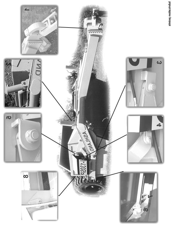
17 TORQUE SPECIFICATIONS LUBRICATION 1. Grease all zerks every 8 hrs of operation with high quality, general-purpose grease. a) Grease until grease flows from around pin. Lubrication Points (see Ill. on next page) 1. Hitch Horizontal and vertical pins. 2. Lift Cylinders Rod end &Trunion; Both left & right sides. 3. Front Arm Pivot Joint Both left & right sides. 4. Apron Cylinders Rod clevis pin; Both left & right sides. 5. Apron Pivot Pin Both left & right sides. 6. Hold-down Rollers Both left & right sides. 7. Floor Rollers Both left & right sides. 8. Tapered Rollers Both left & right sides. 17
18
19 HYDRAULIC SYSTEM Standard Two-Circuit Hydraulic Plumbing The apron cylinders and the push-off cylinder are controlled on the same circuit with the sequence of the operation controlled by a sequence valve. The other hydraulic circuit controls the lift cylinders on the earthmover. *To adjust the sequence valve, see Troubleshooting section. Optional Three-Circuit Hydraulic Plumbing The apron cylinders, push-off cylinder, and lift cylinders are all on separate hydraulic circuits. CAUTION! Relieve all hydraulic pressure before working on the hydraulic system. WARNING! High Pressure Fluid Hazard To prevent serious injury or death from high pressure fluid: a) Relieve pressure on hydraulic system before repairing, adjusting, or disconnecting. b) Wear proper hand and eye protection when searching for leaks. c) Keep all components in good repair. 19

20 PUSHING THE EARTHMOVER The I-130TS was designed to be pushed when equipped with the optional push-bar. However, Ashland Industries, Inc. STRONGLY recommends using extreme caution when pushing the I-130TS earthmover to prevent any unnecessary damage. CAUTION! The I-130TS earthmover must be pushed in a straight line with a maxi-mum of a 100 hp dozer. Do not ram or jar the earthmover while pushing and push at a constant speed. 20
21 TROUBLESHOOTING Introduction With proper care and maintenance, the I-130TS will give many years of reliable service. When a situation arises where the earthmover performance is not satisfactory, this section will give some pointers on finding and correcting the problem. Grease zerk will not take grease. 1. Grease zerk plugged. a) Remove and replace grease zerk. 2. Pin is frozen. a) Remove, clean, and inspect pin. b) Replace pin if necessary. 3. Bushing grease passage is not aligned with grease zerk. a) Remove, clean, inspect, and realign bushing. b) Replace bushing if necessary and realign. Push-off rollers do not roll. 1. The rollers need lubrication. a) Check zerk hole and grease. b) Remove pin, clean, inspect, and replace if necessary. 2. The roller bushing is worn out. a) Remove roller assembly and replace bushing. b) See parts manual. Cylinders will not hold in preset position, i.e. the cylinder creeps. 1. Seals leaking internally. a) Remove and replace seal kit. 21
 Remove acorn nut from end of sequence valve with a ½ wrench.")
22 Machine cuts unevenly. 1. Cutting edges worn unevenly. a) Replace cutting edges. 2. Improperly inflated tires. a) Check air pressure in tires. Apron closes slowly or Apron and push-off are not working well together. 1. Sequence valve needs adjusting. a) Remove acorn nut from end of sequence valve with a ½ wrench. Turn adjustment screw, using a 4mm hex wrench, clockwise until front apron rises before the push-off advances while the earthmover is empty. Turn the adjustment screw an additional ¼ turn clockwise, then replace the acorn nut and tighten. b) Torque check valve assembly and int. pilot plug to 25 ft-lbs maximum. CAUTION! Overtightening check valve assembly and int. pilot plug will cause internal damage to the sequence valve. * Note: Check valve assembly may leak slightly when torqued to 25 ft-lbs. 22
23 Limited Warranty Statement Ashland Industries Inc. warrants each new product to be free from defects in material and workmanship. This warranty is applicable only for the normal service life expectancy of the product or components, not to exceed six consecutive months from the date of delivery of the new Ashland Industries product to the original purchaser, or the date the product is first put into service via a rental agreement or other means, whichever occurs first. Genuine Ashland Industries Inc. replacement parts and components will be warranted for 30 days from date of purchase, or the remainder of the original equipment warranty period, whichever is longer. Under no circumstances will it cover any merchandise or components thereof, which in the opinion of the company, has been subjected to misuse, unauthorized modification, alterations, an accident or if repairs have been made with parts other than those obtained through Ashland Industries Inc. Ashland Industries Inc. in no way warrants Tires since these items are warranted separately by their respective manufacturer. Please call Ashland Industries Inc. to receive phone numbers of tire suppliers. Ashland Industries Inc. in no way warrants wearable items such as cutting edges, front dolly wheel balls, socket halves. Our obligation under this warranty shall be limited to repairing or replacing, free of charge to the original purchaser, any part that, in our judgement, shall show evidence of such defect, provided further that such part shall be returned within 30 days from the date of failure to Ashland Industries Inc. routed through the dealer and distributor from whom the purchase was made, transportation charges prepaid. Upon warranty approval proper credits will be reimbursed for transportation. This warranty shall not be interpreted to render Ashland Industries Inc. liable for injury or damages of any kind or nature to person or property. This warranty does not extend to the loss revenue, extra labor cost associated with downtime, substitute machinery, rental or for any other reason. Except as set forth above, Ashland Industries Inc. shall have no obligation or liability of any kind on account of any of its equipment and shall not be liable for special or consequential damages. Ashland Industries Inc. make no other warranty, expressed or implied, and, specifically, Ashland Industries Inc. disclaims any implied warrant or merchantability or fitness for a particular purpose. Some states or provinces do not permit limitations or exclusions of implied warranties or incidental or consequential damages, so the limitations or exclusion in this warranty may not apply. This warranty is subject to any existing conditions of supply which may direct affect our ability to obtain materials or manufacture replacement parts. Ashland Industries Inc. reserves the right to make improvements in design or changes in specifications at any time, without incurring any obligation to owners of units previously sold No one is authorized to alter, Modify or enlarge this warranty nor the exclusion, limitations and reservations. Ashland Industries Inc. Warranty Department 23
I-130 XL PARTS MANUAL Introduced 4/01/01
 I-130 XL PARTS MANUAL Introduced 4/01/01 Ashland Industries Inc. Hwy. 13 South P.O. Box 717 Ashland, WI. 54806 877-634-4622 Toll Free - phone 715-682-4622 phone 715-682-9717 fax www.ashlandind.com MODEL
I-150-SP PARTS MANUAL
 Quality Equipment since 1953 I-150-SP PARTS MANUAL Revised 9/22/00 Ashland Industries Inc. Hwy. 13 South P.O. Box 717 Ashland, WI. 54806 877-634-4622 Toll Free - phone 715-682-4622 phone 715-682-9717 fax
Model 35 PARTS MANUAL
 Model 35 PARTS MANUAL Version 3-2007 Ashland Industries Inc. 1115 Rail Drive P.O. Box 717 Ashland, WI. 54806 Ph: 877-634-4622 Toll Free Ph: 715-682-4622 Fx: 715-682-9717 www.ashlandind.com Model 35 Scraper
I-150SP PARTS MANUAL
 I-150SP PARTS MANUAL Version 6-04 Ashland Industries Inc. 1115 Rail Drive P.O. Box 717 Ashland, WI. 54806 Ph: 877-634-4622 Toll Free Ph: 715-682-4622 Fx: 715-682-9717 www.ashlandind.com HOW TO ORDER PARTS:
I-175 PARTS MANUAL Version 4-04
 I-175 PARTS MANUAL Version 4-04 Ashland Industries Inc. 1115 Rail Drive P.O. Box 717 Ashland, WI. 54806 Ph: 877-634-4622 Toll Free Ph: 715-682-4622 Fx: 715-682-9717 www.ashlandind.com Model I-175 Scraper
MODEL I-900 SCRAPER INDEX
 I-900 PARTS MANUAL Ashland Industries Inc. Hwy. 13 South P.O. Box 717 Ashland, WI. 54806 877-634-4622 Toll Free - phone 715-682-4622 phone 715-682-9717 fax www.ashlandind.com MODEL I-900 SCRAPER HOW TO
I-110 PARTS MANUAL Updated 3/21/01
 I-110 PARTS MANUAL Updated 3/21/01 Ashland Industries Inc. Hwy. 13 South P.O. Box 717 Ashland, WI. 54806 877-634-4622 Toll Free - phone 715-682-4622 phone 715-682-9717 fax www.ashlandind.com MODEL I-100,
HOW TO ORDER PARTS: Unless this is done, we cannot provide prompt service or assure shipment of the correct parts.
 How to Order Parts HOW TO ORDER PARTS: IMPORTANT Parts must be ordered through your local authorized ASHLAND dealer. Be sure to state MODEL and SERIAL NUMBER of your machine, PART NUMBER, DESCRIPTION and
HOW TO ORDER PARTS: Unless this is done, we cannot provide prompt service or assure shipment of the correct parts.
 HOW TO ORDER PARTS: IMPORTANT Parts must be ordered through your local authorized ASHLAND dealer. Be sure to state MODEL and SERIAL NUMBER of your machine, PART NUMBER, DESCRIPTION and QUANTITY needed.
I-130XL2 PARTS MANUAL
 EARTHMOVERS I-130XL2 PARTS MANUAL ver 0309-22128 Inc. 1115 Rail Drive P.O. Box 717 Ashland, WI. 54806 Ph: 877-634-4622 Toll Free Ph: 715-682-4622 Fx: 715-682-9717 www.ashlandind.com How to Order Parts
I-175XL2 PARTS MANUAL
 I-175XL2 PARTS MANUAL I-175XL2 ver 5-06 Ashland Industries Inc. 1115 Rail Drive P.O. Box 717 Ashland, WI. 54806 Ph: 877-634-4622 Toll Free Ph: 715-682-4622 Fx: 715-682-9717 www.ashlandind.com HOW TO ORDER
EARTHMOVERS I-110XL2 PARTS MANUAL. ver
 EARTHMOVERS I-110XL2 PARTS MANUAL ver 1108-22103 Inc. 1115 Rail Drive P.O. Box 717 Ashland, WI. 54806 Ph: 877-634-4622 Toll Free Ph: 715-682-4622 Fx: 715-682-9717 www.ashlandind.com How to Order Parts
EARTHMOVERS I-110XL2 PARTS MANUAL. ver
 EARTHMOVERS I-110XL2 PARTS MANUAL ver 0109-22128 Inc. 1115 Rail Drive P.O. Box 717 Ashland, WI. 54806 Ph: 877-634-4622 Toll Free Ph: 715-682-4622 Fx: 715-682-9717 www.ashlandind.com How to Order Parts
I-950 PARTS MANUAL. Ver. 1010
 I-950 PARTS MANUAL Ver. 1010 Ashland Industries Inc. ive Ashland, WI. 54806 Ph: 877-634-4622 Toll Free Ph: 715-682-4622 Fx: 715-682-9717 www.ashlandind.com Serial Number WELCOME TO OUR NEW CUSTOMERS! Thank
I-950 PARTS MANUAL. Ver. 0610
 I-950 PARTS MANUAL Ver. 0610 Ashland Industries Inc. ive Ashland, WI. 54806 Ph: 877-634-4622 Toll Free Ph: 715-682-4622 Fx: 715-682-9717 www.ashlandind.com WELCOME TO OUR NEW CUSTOMERS! Thank you for your
Ashland I-200TS4. Earthmovers. Parts Manual. Ashland Industries. Crafting Quality since 1953! ver. 0612
 Ashland Earthmovers I-200TS4 Parts Manual ver. 0612 Ashland Industries Crafting Quality since 1953! 1115 Rail Drive P.O. Box 717 Ashland, WI U.S.A. Toll Free: (877) 634-4622 Business: (715) 682-4622 Fax:
Table of Contents Categorized Listing
 ASHLAND SCRAPERS 1 Welcome and Serial Number 2500SS 1 Safety Guidelines 2 Assembly - 2500SS-002 3 Actuating Frame - 2500SS 4 Apron - 2500SS 5 Apron - 2500SS - (breakout) 6 Beam & Hub - 2500SS 7 Bowl -
MODEL 45 SCRAPER INDEX
 MODEL 45 SCRAPER HOW TO ORDER PARTS: Be sure to state MODEL and SERIAL NO. of machine, PARTS NO., DESCRIPTION, and QUANTITY wanted. Unless this is done, we cannot provide prompt service or assure shipment
Table of Contents Alphabetized Listing
 A Apron Assembly (130-1020) 8 Apron Cylinder (#A125050) 4" X 13" 17 ASHLAND SCRAPERS 1-35 Assembly - Push Off (110-130) 11 Assembly - Wheel Front (130) 14 Assembly - Wheel Rear (130X) Optional 16 B Bowl
Table of Contents Categorized Listing
 1 Introduction 1 Operation and Maintenance 2 Safety Guidelines 5 Assembly - Main - WG-25-2-002 6 Actuating Frame - 600988 7 Apron & Bucket-25CS 8 Bowl - 25CS 9 Frame - 601086 10 Wheel Assembly - 25 11
Table of Contents Categorized Listing
 1 Serial Number 1 How to Order Parts 2 Parts - Transport Locks (18HD) 3 Instruction: Operation and Maintenance 4 Instruction: Operation and Maintenance 5 Safety Guidelines 7 CS18HD Assembly 8 Front Frame
Operation and Parts Manual
 Operation and Parts Manual 3-Point PTO and Hydraulic Stump Grinders Models: SC-25 and SC-25H SC-50 and SC-50H Safety Operation Maintenance Repair Troubleshooting Parts Parts SC-50 and SC-50-H Stumpbuster
MODEL 25 SCRAPER INDEX
 MODEL 25 SCRAPER HOW TO ORDER PARTS Be sure to state MODEL and SERIAL NO. of machine, PARTS NO., DESCRIPTION, and QUANTITY wanted. Unless this is done, we cannot give you prompt service or send the correct
Parts Manual HDW WG-HDW /18 S.N PH:
 Parts Manual HDW-3217-18 WG-HDW3217-18 10/18 S.N. 24715+ 1 Table of Contents Introduction 3 Disc Harrow Specifications 4 Frame 5 Lift Cylinder 8 Disc Gang 9 Jack 10 Oil Bath Bearing 11 Wheel Carriage Assembly
MODEL L-9, L-10 LAND LEVELER INDEX
 HOW TO ORDER PARTS: MODEL L-9, L-10 LAND LEVELER Be sure to state MODEL and SERIAL NO. of machine, PARTS NO., DESCRIPTION, and QUANTITY wanted. Unless this is done, we cannot provide prompt service or
Parts Manual 25CS WG-25CS PH:
 Parts Manual 25CS WG-25CS-002 10-18 1 Table of Contents Introduction 3 Scraper Specifications 4 Assembly 5 Frame 6 Frame Expanded 7 Wheel Assembly 8 Apron 9 Apron Expanded 10 Bowl 11 Actuating Frame 12
Parts Manual 155XL2 WG-155X /18 PH:
 Parts Manual 155XL2 WG-155X-001 10/18 1 Table of Contents Introduction 3 Scraper Specifications 4 Assembly 5 Bowl 6 Rear Wheel Assembly 8 Pushoff 9 Apron 11 Front Section 12 Ball/Socket Assembly 13 Pole
Parts Manual 155TS2 WG-155T-R /18 PH:
 Parts Manual 155TS2 WG-155T-R-002 10/18 1 Table of Contents Introduction 3 Scraper Specifications 4 Assembly 5 Ashland Hitch 6 Bowl 7 Wheel Assembly 9 Pushoff 10 Apron 12 Front Section 13 Lift Cylinder
Parts Manual 2500SS WG-GH PH:
 Parts Manual 2500SS WG-GH2500-002 5-18 1 Table of Contents Introduction 3 Scraper Specifications 4 Assembly 5 Frame 6 Frame Expanded 7 Oscillating Beam 8 Wheel Assembly 9 Apron 10 Apron Expanded 11 Actuating
Parts Manual 2500SS WG-GH PH:
 Parts Manual 2500SS WG-GH2500-004 11-18 1 Table of Contents Introduction 3 Scraper Specifications 4 Assembly 5 Frame 6 Frame Expanded 7 Oscillating Beam 8 Wheel Assembly 9 Apron 10 Apron Expanded 11 Actuating
SHEYENNE TELE-BOOM OWNERS MANUAL OPERATOR INSTRUCTIONS PARTS BOOK
 SHEYENNE TELE-BOOM OWNERS MANUAL OPERATOR INSTRUCTIONS PARTS BOOK 701 Lenham Ave. SW PO Box 647 Cooperstown ND 58425 1-800-797-1883 701-797-2700 * 701-797-2584 Fax www.sheyennemfg.com TABLE OF CONTENTS
Parts Manual 220TS4 WG-220T PH:
 Parts Manual 220TS4 WG-220T-4-005 5-18 1 Table of Contents Introduction 3 Scraper Specifications 4 Assembly 5 Ashland Hitch 6 Bowl 7 Wheel Assembly 10 Pushoff 12 Apron 14 Front Section 15 Apron Cylinder
Parts Manual 2012CS WG-2012-CS-4-001
 Parts Manual 2012CS WG-2012-CS-4-001 4-18 Table of Contents Introduction 3 Scraper Specifications 4 Assembly 5 Ashland Hitch 6 Bowl 7 Apron 8 Front Section 10 Optional - Laser Mast 12 Rear Section 13 Wheel
Parts Manual 2014CS WG-2014-CS PH:
 Parts Manual 2014CS WG-2014-CS-6-003 11-18 24591+ 1 Table of Contents Introduction 3 Scraper Specifications 4 Assembly 5 Ashland Hitch 6 Bowl 7 Apron 8 Front Section 10 Optional Laser Mast 12 Rear Section
Parts Manual 215TS2 WG-215T PH:
 Parts Manual 215TS2 WG-215T-004 10-18 1 Table of Contents Introduction 3 Scraper Specifications 4 Assembly 5 Ashland Hitch 6 Bowl 7 Wheel Assembly 10 Pushoff 12 Apron 14 Front Section 15 Apron Cylinder
OPERATION AND MAINTENANCE MANUAL WASP, Inc. United Airlines Shock Mount Cargo Cart Model No. A03439D
 OPERATION AND MAINTENANCE MANUAL WASP, Inc. United Airlines Shock Mount Cargo Cart Model No. A03439D WASP RECORD OF REVISIONS REV. ISSUE DATE BY REV. ISSUE DATE BY NO. DATE INSERTED NO. DATE INSERTED Original
MODEL HD-BTC. Installation, Operation & Repair Parts Information REV041416
 MODEL HD-BTC Installation, Operation & Repair Parts Information REV041416 TABLE OF CONTENTS SAFETY INSTRUCTIONS 1 DEFINITIONS 1 SPECIFICATIONS 2 INSTALLATION INSTRUCTIONS 2 OPERATING INSTRUCTIONS 2 MAINTENANCE
Warranty Information Operators Manual Installation Instructions. Sudenga
 Warranty Information Operators Manual Installation Instructions Sudenga Rust Sales, Inc. 2964 164 th Ave SE Harwood, ND 58042 (800) 478-7801 (701) 282-9194 www.hopperwalker.com Limited Warranty Statement
SCHMEISER BANTAM LEVELER ASSEMBLY & PARTS MANUAL T. G. SCHMEISER CO., INC.
 SCHMEISER BANTAM LEVELER ASSEMBLY & PARTS MANUAL T. G. SCHMEISER CO., INC. P.O. BOX 07 FRESNO, CA 937-07 (559) 68-88 FAX (559) 68-379 www.tgschmeiser.com VERSION.3 OCTOBER 03 COPY RIGHT 03 T.G.SCHMEISER
SCHMEISER TILL AN PAK HYDRAULIC TRANSPORT KITS ASSEMBLY & PARTS MANUAL
 SCHMEISER TILL AN PAK HYDRAULIC TRANSPORT KITS ASSEMBLY & PARTS MANUAL T.G. SCHMEISER CO., INC. P.O. BOX 07 FRESNO, CA. 97 (559) - FAX (559) -79 www.tgschmeiser.com VERSION.a 0-0 COPYRIGHT 0 T.G.SCHMEISER
MODEL EF Full Circle Tire Spreader
 MODEL EF Full Circle Tire Spreader Installation, Operation & Repair Parts Information Branick Industries, Inc. 4245 Main Avenue P.O. Box 1937 Fargo, North Dakota 58103 REV. 062917 P/N: 81-0050C CAUTION
W & A 12 ROW TOP LEVELING STACKER LEVEL BANDER
 W & A 12 ROW TOP LEVELING STACKER LEVEL BANDER NO. 3640 OPERATOR S MANUAL TO THE OWNER: Congratulations on your purchase of a new W & A Top Leveling Stacker Level Bander. Your selection is an indication
OPERATORS MANUAL SAFETY & WARRANTY SECTION
 OPERATORS MANUAL SAFETY & WARRANTY SECTION KMW Ltd. 198 N. Hwy 281 Great Bend, Kansas 67530 800 445-7388 Fax 620 793-6737 ïïïkâãïäç~çéêëkåçã SAFETY FIRST This symbol, the industry s Safety Alert Symbol,
Parts Book 612N, 812N, 642N, 842N, 862N 714NT, 814NT, 742NT, 842NT, 862NT
 Parts Book 612N, 812N, 642N, 842N, 862N 714NT, 814NT, 742NT, 842NT, 862NT Wishek Mfg. LLC 112 South 2nd Street PO Box 185 Wishek, ND 58495 (701) 452-2449 www.wishekmfg.com WARRANTY/ PARTS RETURN POLICY
Planting Components. Operator s/parts Manual
 Operator s/parts Manual Unit Mount Conservation Coulter and Spring Package Attachment for JD 7000, JD 7200, White 6100, Kinze Planters and Great Plains Row Units Planting Components! Read the operator
Planting Components. Operator s/parts Manual Vantage II
 Operator s/parts Manual Vantage II Planting Components! Read the operator s manual entirely. When you see this symbol, the subsequent instructions and warnings are serious - follow without exception. Your
Westfield, Mayrath, Hutchinson, Wheatheart
 Warranty Information Operators Manual Installation Instructions Westfield, Mayrath, Hutchinson, Wheatheart Rust Sales, Inc. 2964 164 th Ave SE Harwood, ND 58042 (800) 478-7801 (701) 282-9194 www.hopperwalker.com
Thatching Reel Reelmaster 450 D, 4500 D, 335 D & 3500 D
 Form No. 3350 8 Thatching Reel Reelmaster 450 D, 4500 D, 335 D & 3500 D Model No. 0373 Serial No. 5000000 and Up Model No. 03730 Serial No. 5000000 and Up Operator s Manual English (EN) Introduction Read
SHEYENNE TELE-SAW MODEL 21 OWNERS MANUAL OPERATOR INSTRUCTIONS PARTS BOOK
 SHEYENNE TELE-SAW MODEL 21 OWNERS MANUAL OPERATOR INSTRUCTIONS PARTS BOOK 701 Lenham Ave. - P.O. Box 647 Cooperstown, ND 58425 Office (701) 797-2700 Fax (701) 797-2584 Toll Free (800) 797-1883 www.sheyennemfg.com
GRADER BLADE ASSEMBLY & PARTS MANUAL
 SCHMEISER GRADER BLADE ASSEMBLY & PARTS MANUAL UP TO 0 FT. WIDE T. G. SCHMEISER CO., INC. P.O. BOX 07 FRESNO, CA 937-07 (9) - FAX (9) -379 VERSION. 0 03 COPYRIGHT 03 T.G.SCHMEISER CO., INC INTRODUCTION
4750 Drill. Repair Parts
 4750 Drill Repair Parts #615997-2016 Identification Your CrustBuster drill is identified by a Serial Number and Model Number. Record these numbers in the spaces provided in this manual and refer to them
Planting Components. Operator s/parts Manual Heavy Duty Fertilizer Coulter
 Operator s/parts Manual Heavy Duty Fertilizer Coulter Planting Components Read the operator manual entirely. When you see this symbol, the subsequent instructions and warnings are serious - follow without
TABLE OF CONTENTS. Warranty Disclaimers Delivery Checklist After Sale Checklist Safety Set Up... 8
 TABLE OF CONTENTS Pickett Equipment Warranty... 2 Warranty Disclaimers... 3 Delivery Checklist... 4 After Sale Checklist... 4 Safety... 5-7 Set Up... 8 Machine Adjustments and Operation... 9 Maintenance
Operator s/parts Manual
 Operator s/parts Manual 3-Point Solid Stand Drills Pull Hitch Package Manufacturing, Inc. P.O. Box 5060 Salina, Kansas 67402-5060! Read the operator s manual entirely. When you see this symbol, the subsequent
MODEL 5500 Tire Repair Station
 MODEL 5500 Tire Repair Station Installation, Operation and Repair Parts Information Branick Industries, Inc. 4245 Main Ave P.O. Box 1937 Fargo, North Dakota 58103 P/N: 81-0047C TABLE OF CONTENTS SAFETY
Operator s/parts Manual
 1--1 4/8/04 Operator s/parts Manual 30 3-Section Flat Fold Marker Manufacturing, Inc. P.O. Box 5060 Salina, Kansas 67402-5060! Read the Operator s manual entirely. When you see this symbol, the subsequent
4200 & 6200 Owner s Manual & Parts Book
 00 & 00 Owner s Manual & Parts Book Purchase Date Serial Number Model Number Tractor Model PN: - Dealer Date --0 Description Page To The Owner & Maintenance Safety Precautions & Torque Specifications Skid
MODEL L/R/EF Sectional Tire Spreader
 MODEL L/R/EF Sectional Tire Spreader Installation, Operation & Repair Parts Information Branick Industries, Inc. 4245 Main Avenue P.O. Box 1937 Fargo, North Dakota 58103 REV08032016 P/N: 81-0195E TABLE
Combine Grain Tank Extension Tip-Up Kit CIH MZ315P Fits Case IH 7120, 7230, 7240 w/ 24 POWER FOLDING EXTENSION PANELS
 10/6/2016 8E00006,Rev AB Combine Grain Tank Extension Tip-Up Kit CIH MZ315P Fits Case IH 70, 7230, 720 w/ 2 POWER FOLDING EXTENSION PANELS OPERATOR / assembly MANUAL PLACE IN COMBINE CAB AFTER ASSEMBLY
Instruction Manual and Parts List
 Instruction Manual and Parts List KW Products Inc. Copyright 2003, All Rights Reserved Equipment, specifications, options and accessories subject to change without notice Part #108-3050-32 521 WARRANTY
OPERATION AND MAINTENANCE MANUAL WASP, Inc. 757 Towbar Model No. A01568D
 OPERATION AND MAINTENANCE MANUAL WASP, Inc. 757 Towbar Model No. A01568D WASP RECORD OF REVISIONS REV. ISSUE DATE BY REV. ISSUE DATE BY NO. DATE INSERTED NO. DATE INSERTED Original May 19/97 001 June 10/03
Combine Grain Tank Extension Tip-Up Kit CIH MZ315C Fits Case IH 7120, 7230, 7240 w/ POWER FOLD COVER & 24 PANELS
 9/22/2016 8E000048,Rev AB Combine Grain Tank Extension Tip-Up Kit CIH MZ315C Fits Case IH 7120, 7230, 7240 w/ POWER FOLD COVER & 24 PANELS OPERATOR / assembly MANUAL PLACE IN COMBINE CAB AFTER ASSEMBLY
MODEL 5120 Tire Repair Station
 MODEL 5120 Tire Repair Station 00-0049 Installation, Operation & Repair Parts Information Branick Industries, Inc. 4245 Main Avenue P.O. Box 1937 Fargo, North Dakota 58103 REV01182017 P/N: 81-0058G CAUTION
ENGINE DRIVEN ROTARY MOWER
 ENGINE DRIVEN ROTARY MOWER Operation, Service & Parts Manual For Models ERM-413, 416, & 617 April 2009 Form: ERMHydMower TABLE OF CONTENTS SECTION DESCRIPTION...PAGE 1 Introduction... 1 2 Preparation...2
Operator s Manual. Go Galvanized! YOU'RE ALWAYS AHEAD...WITH A MODERN BEHIND.
 SUMMER 2008 C2 tilting grader blade Operator s Manual YOU'RE ALWAYS AHEAD...WITH A MODERN BEHIND. 003-5336 003-5342 003-5531 003-5544 P.O. Box 790 Beaumont, Tx 77704 409.833.2665 1.800.231.8198 Fax: 409.726.8333
Combine Grain Tank Extension Tip-Up Kit CIH MZ315C FITS CASE IH 7120, 7230, 7240 w/ POWER FOLD COVER & 24 PANELS OPERATOR / ASSEMBLY MANUAL
 5/6/2016 8E000048,Rev AA Combine Grain Tank Extension Tip-Up Kit CIH MZ315C FITS CASE IH 7120, 7230, 7240 w/ POWER FOLD COVER & 24 PANELS OPERATOR / ASSEMBLY MANUAL PLACE IN COMBINE CAB AFTER ASSEMBLY
GRADING SCRAPERS INDUSTRIAL SERIES OPERATION, SERVICE & PARTS MANUAL FOR MODELS: GSI7-SS, GSI7, GSI8, GSI10, & GSI12.
 GRADING SCRAPERS INDUSTRIAL SERIES OPERATION, SERVICE & PARTS MANUAL FOR MODELS: GSI7-SS, GSI7, GSI8, GSI10, & GSI12 September 2006 FORM: IndGradingScrpr.QXD TABLE OF CONTENTS Safety Information......................1-2
OWNER'S MANUAL L A W N R O L L E R PRT-481S BH. Safety Assembly Operation Repair Parts Maintenance. Visit us on the web!
 OWNER'S MANUAL L A W N R O L L E R ROLLER MODEL: PRC- BH PRT- BH PRT-S BH PRT-S BH Safety Assembly Operation Repair Parts Maintenance Recommended for use with Riding Mowers, Lawn or Garden Tractors, and
Operator s Manual & Repair Parts Manual. Do Not Use or Operate This Equipment Until You Have Read and Understand This Manual
 Operator s Manual & Repair Parts Manual Do Not Use or Operate This Equipment Until You Have Read and Understand This Manual The purpose of this manual is to explain maintenance requirements and adjustments
ATV TRACK KIT. Operator s Manual Installation Instructions Service Instructions Replacement Parts List. Effective Date: October, 2012
 p/n 2258-642 ATV TRACK KIT Operator s Manual Installation Instructions Service Instructions Replacement Parts List Track Assembly Kits (p/n 1436-204) Mounting Assembly Kits (p/n 1436-205) 1436-815) Effective
HydroTote Trailer Hydroject Aerator
 Form No. 3355 89 Rev. C HydroTote Trailer Hydroject Aerator Model No. 09833 Serial No. 6000000 and Up Operator s Manual English (EN, GB) Contents Page Introduction................................. Safety......................................
SCHMEISER VARITRAK LAND LEVELER ASSEMBLY & PARTS MANUAL
 SCHMEISER VARITRAK LAND LEVELER ASSEMBLY & PARTS MANUAL, 0, & FT. WIDE T. G. SCHMEISER CO., INC. P.O. BOX 07 FRESNO, CA 937-07 (559) - FAX (559) -379 www.tgschmeiser.com VERSION. 00 COPYRIGHT 00 T.G.SCHMEISER
BALE KING GT40 Grain Feeder Operator's & Parts Manual Last Update: November 20, 2014 Bridgeview Manufacturing Inc - 1 -
 BALE KING GT40 Grain Feeder Operator's & Parts Manual Last Update: November 20, 2014 Bridgeview Manufacturing Inc - 1 - Your Authorized Dealer: Your Serial Number: The Serial Number is located on the tank.
SAC Liquid Manure Flow Meter
 LM300000 REV A 11/11/2009 QUALITY PEOPLE, QUALITY PRODUCTS SAC Liquid Manure Flow Meter Operation and Service Manual ASSEMBLY CALIBRATION OPERATION REPLACEMENT PARTS READ complete manual CAREFULLY BEFORE
Instruction Manual. ATV Plow Tube System
 Instruction Manual ATV Plow Tube System Manual Conventions This manual uses the following symbols to help differentiate between different kinds of information. The safety symbol is used with a key word
450 & Slant Top Owner s Manual & Parts Book
 0 & 0 - Slant Top Owner s Manual & Parts Book Purchase Date Serial Number Model Number Tractor Model PN: - Dealer Date -- Contents Description Page To The Owner & Maintenance Safety Precautions & Torque
Planting Components. Operator s/parts Manual. Row Cleaner VIII. Terra-Tine
 Operator s/parts Manual Terra-Tine Row Cleaner VIII Planting Components! Read the operator s manual entirely. When you see this symbol, the subsequent instructions and warnings are serious - follow without
Planting Components. Operator s/parts Manual Terra-Tine. Row Cleaner
 Operator s/parts Manual Terra-Tine Row Cleaner Planting Components! Read the operator s manual entirely. When you see this symbol, the subsequent instructions and warnings are serious - follow without
DISC HARROW PART'S MANUAL DHP8/10/12. RHINO 1020 S. Sangamon Ave. Gibson City, IL
 DISC HARROW DHP8/10/12 Published 03/16 PART'S MANUAL P/N 00789085P An Operator's Manual was shipped with the equipment in the Manual Canister. This Operator's Manual is an integral part of the safe operation
High Lift Transmission Jack Max. Capacity: kg (1,000 lbs.)
") 655 EISENHOWER DRIVE OWATONNA, MN 55060-0995 USA PHONE: (507) 455-7000 TECH. SERV.: (800) 533-6127 FAX: (800) 955-8329 ORDER ENTRY: (800) 533-6127 FAX: (800) 283-8665 INTERNATIONAL SALES: (507) 455-7223
655 EISENHOWER DRIVE OWATONNA, MN 55060-0995 USA PHONE: (507) 455-7000 TECH. SERV.: (800) 533-6127 FAX: (800) 955-8329 ORDER ENTRY: (800) 533-6127 FAX: (800) 283-8665 INTERNATIONAL SALES: (507) 455-7223
LIMITED WARRANTY DISCLAIMER OF IMPLIED WARRANTIES & CONSEQUENTIAL DAMAGES
 Published 08/15 LIMITED WARRANTY Bush Hog warrants to the original purchaser of any new Bush Hog equipment, purchased from an authorized Bush Hog dealer, that the equipment be free from defects in material
W & A 12 ROW TOP LEVELING STACKER LEVEL BANDER
 W & A 12 ROW TOP LEVELING STACKER LEVEL BANDER NO. 3640 OPERATOR S MANUAL TO THE OWNER: Congratulations on your purchase of a new W & A Top Leveling Stacker Level Bander. Your selection is an indication
INDUSTRIAL SCRAPER. Operation, Service & Parts Manual For 2G2 Series. Form: 2G2Book.pm65\10-01
 INDUSTRIAL SCRAPER Operation, Service & Parts Manual For 2G2 Series Form: 2G2Book.pm65\10-01 October 2001 TABLE OF CONTENTS Preparation... 1 Safety Information... 2 General Information... 3 Maintenance/Safety...
OPERATOR S MANUAL REPAIR PARTS CATALOG. Models: SCP-51 & SCP-71 SCP-52 & SCP-72 SCP-91 & SCP-111 SCP-92 & SCP-112 BRILLION FARM EQUIPMENT
 OPERATOR S MANUAL REPAIR PARTS CATALOG Subsoil Chisel Plow Models: SCP-51 & SCP-71 SCP-52 & SCP-72 SCP-91 & SCP-111 SCP-92 & SCP-112 IMPORTANT! Repairs cannot be purchased retail direct from factory. Order
Verticutter Reelmaster 5510/5610 Series Cutting Unit with 7in Reel
 Form No. 3354 79 Rev B Verticutter Reelmaster 550/560 Series Cutting Unit with 7in Reel Model No. 03684 Serial No. 6000000 and Up Operator s Manual English (EN) Contents Page Introduction................................
Owner s Manual ATV ACCESSORIES MANUFACTURING QUALITY LAWN CARE EQUIPMENT SINCE Model Numbers Receiver Hitch Plow Blade 2140
 MANUFACTURING QUALITY LAWN CARE EQUIPMENT SINCE 1945 Owner s Manual Model Numbers Receiver Hitch 10260 Plow Blade 2140 IMPORTANT Read and follow all Safety Precautions and Instructions Before Operating
Angle Grinder Holder
 Angle Grinder Holder Owner s Manual WARNING: Read carefully and understand all ASSEMBLY AND OPERATION INSTRUCTIONS before operating. Failure to follow the safety rules and other basic safety precautions
Combine Grain Tank Extension Tip-Up Kit CIH MX410P Fits Case IH 8240, 9240 w/ 410 bu. POWER FOLD Extension
 10/25/2017 8E000050,Rev AB Combine Grain Tank Extension Tip-Up Kit CIH MX410P Fits Case IH 8240, 9240 w/ 410 bu. POWER FOLD Extension OPERATOR / assembly MANUAL PLACE IN COMBINE CAB AFTER ASSEMBLY FOR
MODELS CX10 and CX20 INDUSTRIAL PUMPS INSTRUCTIONS AND SERVICE MANUAL
 MODELS CX0 and CX20 INDUSTRIAL PUMPS INSTRUCTIONS AND SERVICE MANUAL NOTE! To the installer: Please make sure you provide this manual to the owner of the equip ment or to the responsible party who maintains
4/3/2012 8E000024,Rev C Combine Grain Tank Extension Tip-Up Kit CIH250MX FITS CASE IH 5088 W/ 24 MANUAL FOLDING EXTENSION PANELS OPERATOR / ASSEMBLY M
 4/3/2012 8E000024,Rev C Combine Grain Tank Extension Tip-Up Kit CIH250MX FITS CASE IH 5088 W/ 24 MANUAL FOLDING EXTENSION PANELS OPERATOR / ASSEMBLY MANUAL PLACE IN COMBINE CAB AFTER ASSEMBLY FOR FUTURE
CAUTION CAUTION indicates a potentially hazardous situation which, if not avoided, may result in minor or moderate injury.
 Instruction Manual Notes: Page Manual Conventions This manual uses the following symbols to help differentiate between different kinds of information. The safety symbol is used with a key word to alert
AG PRODUCTS, LTD. YOU RE ALWAYS AHEAD... WITH A MODERN BEHIND.
 SUMMER 2016 BADGER DISC HARROW Operator s Manual 011-1156 011-1166 001-1501 001-1501-1 011-1167 001-1501-2 001-1501-3 011-1176 001-1501-4 011-1177 MODERN AG PRODUCTS, LTD. YOU RE ALWAYS AHEAD... WITH A
OWNER S MANUAL 40 LAWN AERATOR SAT-40 BH. Assembly Installation Operation Repair Parts. Visit us on the web! MODEL:
 OWNER S MANUAL 40 LAWN AERATOR MODEL: SAT-40 BH Assembly Installation Operation Repair Parts For the latest product updates & setup tips: Visit us on the web! www.brinly.com Important: This manual contains
MK AUGERS POWER SWING KIT ASSEMBLY & OPERATION MANUAL
 MK AUGERS POWER SWING KIT ASSEMBLY & OPERATION MANUAL Read this manual before using product. Failure to follow instructions and safety precautions can result in serious injury, death, or property damage.
Linear Actuator. Installation Manual. warranty installation parts list. Linear Actuator Installation Manual Page 1
 Linear Actuator Installation Manual warranty installation parts list January 2004 Linear Actuator Installation Manual Page 1 MA1221B12 Warranty Information Chore-Time Equipment ( Chore-Time ) warrants
TABLE OF CONTENTS DESCRIPTION. Safety Instructions & Safety Sign Locations Operating Instructions Assembly Instructions...
 TABLE OF CONTENTS DESCRIPTION PAGE Warranty... 1 Safety Instructions & Safety Sign Locations... 2 Operating Instructions... 3 Assembly Instructions... 5 500 & 600 Snowblower Drawings... 8 500 & 600 Snowblower
14", 18" & 24" Fiberglass Turbo Fans Installation & Operator s Instruction Manual
 14", 18" & 24" Fiberglass Turbo Fans Installation & Operator s Instruction Manual 09484:09#52
Auto-Locking Trailer Coupler
 Auto-Locking Trailer Coupler 7-Ton Capacity Owner s Manual WARNING: Read carefully and understand all ASSEMBLY AND OPERATION INSTRUCTIONS before operating. Failure to follow the safety rules and other
Lubricator Gun: 10,000 psi (700 bar) Maximum Delivery Pressure when disconnected from Dispenser
 Maximum Delivery Pressure when disconnected from Dispenser") INSTRUCTIONS-PARTS LIST 30 455 INSTRUCTIONS This manual contains important warnings and information. READ AND KEEP FOR REFERENCE. Rev. C Supercedes B Hand-Operated Portable Grease Dispenser Buckshot Luber
INSTRUCTIONS-PARTS LIST 30 455 INSTRUCTIONS This manual contains important warnings and information. READ AND KEEP FOR REFERENCE. Rev. C Supercedes B Hand-Operated Portable Grease Dispenser Buckshot Luber
Warnings and Precautions FAILURE TO READ, UNDERSTAND AND FOLLOW THESE INSTRUCTIONS MAY LEAD TO SERIOUS INJURY OR DEATH!
 Instruction Booklet 2006 Summit ATV Pak-Mule Single Axle 84000 Summit ATV Pak-Mule Tandem Axle 84002!! READ ME FIRST!!! Please read carefully BEFORE using you new Summit ATV Product. Congratulations! You