THE REX DESIGN REPLACEABLE BEARING
|
|
|
- Adele Berry
- 5 years ago
- Views:
Transcription

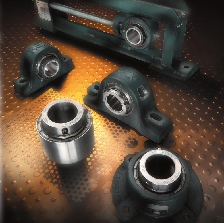
1 Bearings Rexnord Roller Bearings (English-Inch)
2

3 THE REX DESIGN EASY BEARING CLEARANCE ADJUSTMENT Can be field adjusted to meet application needs. REPLACEABLE BEARING Available in Normal Duty, Medium Duty, Heavy Duty and Adapter Sleeve mounting to suit the load and installation requirements. SHAFT READY Prelubricated with our standard grease for normal operation; other lubricants available for special conditions. FULLY SELF-ALIGNING Spherical roller bearing to accommodate operational and installation misalignment. CARBURIZED RACEWAYS Case-carburized inner races provide a hard, fatigue resistant surface, and a tough, crack resistant, ductile core. RUGGED HOUSING Standard material cast iron. Steel or ductile iron available on request. MULTIPLE HOUSING STYLES Providing mounting features to match the operational and structural requirements. INTERCHANGEABLE SEALS Three types of seals to match the application requirements: Z Seal, for the broad range of normal operating conditions; K Seal, for dusty, dirty conditions; M Seal, for protection against liquid contamination. For extra protection under severe conditions, auxiliary caps are also available. TABLE OF CONTENTS Page Number ROLLER BEARINGS INTRODUCTION Rex Bearing Design... 1 Bearing Index Nomenclature Self-Alignment... 6 Shaft Mounting... 7 Seals... 8 DIMENSIONS Pillow Blocks Flange Blocks Flange Cartridge Blocks Cartridge Blocks Duplex Units Takeups Bearing Only Replacement Parts Page Number INTERCHANGEABILITY Code... 41, 57 Code Metric ENGINEERING/SELECTION Bearing Considerations Housing, Seal, Mounting Considerations Shafting and Floating Units Bearing Selection Load Ratings Life Adjustment Factors Vibration Analysis Seal Selection INSTALLATION LUBRICATION ALPHABETICAL INDEX


4 SELF-ALIGNING ROLLER BEARINGS Page Normal Duty ZEP 2000, 5000 Series Medium Duty ZEP Normal Duty, Fixed ZA 2000 Series Normal Duty, Floating ZAS 2000 Series Medium Duty, ZA 3000 Series Heavy Duty, Fixed ZP 5000 Series Heavy Duty, Floating ZPS 5000 Series Adapter, Fixed ZP 9000 Series Adapter, Floating ZPS 9000 Series Steel, Fixed ZA Series Steel, Floating ZAS Series PILLOW BLOCKS FLANGE BLOCKS Page Normal Duty ZB 2000 Series Medium Duty ZB 3000 Series Normal Duty ZEF 2000 Series Heavy Duty, Fixed ZF 5000 Series Heavy Duty, Floating ZFS 5000 Series Adapter, Fixed ZF 9000 Series Adapter, Floating ZFS 9000 Series FLANGE CARTRIDGE BLOCKS Page Normal Duty ZBR 2000 Series Medium Duty ZBR 3000 Series Heavy Duty ZBR 5000 Series CARTRIDGE BLOCKS Page Normal Duty ZCS 2000 Series Heavy Duty ZCS 5000 Series Normal Duty ZMC 2000 Series Heavy Duty ZMC 5000 Series Adapter ZMC 9000 Series DUPLEX UNITS Page Normal Duty ZD 2000 Series Heavy Duty ZD 5000 Series


5 TAKE-UP BLOCKS Page Center Pull ZT Page Protected Screw ZN TAKE-UPS Page Heavy Duty Center Pull ZHT Page Spring Loaded ZST Page Normal Duty Protected Screw ZNT Page Normal Duty ZAT Page Elevator Boot End ZFT Page Elevator Head End ZGT ALPHABETICAL INDEX Page ZA Pillow Block...12, 13 ZAS Pillow Block, Floating...12, 13 ZAT Take-up ZB Flange Block...18, 19 ZBR Flange Cartridge Block... 24, 25, 26 ZCS Cartridge Block ZD Duplex Unit ZEF Flange Block ZEP Pillow Block...10, 11 ZF Flange Block, Heavy Duty...21, 22 Page ZFS Flange Block, Heavy Duty Floating...21, 22 ZFT Take-up, Elevator, Boot End ZGT Take-up, Elevator, Head End ZHT Take-up, Heavy Duty ZMC Cartridge Block...29, 30 ZNT Take-up ZP Pillow Block, Heavy Duty...14, 15 ZPS Pillow Block, Floating...14, 15 ZST Take-up, Heavy Duty, Spring Loaded ZT Take-up Block, Center pull
6 NOMENCLATURE Z A Z Clearance seal Seal Type K Light contact seal M Heavy contact seal A Pillow block, normal duty AS Pillow block, floating P Pillow block, heavy duty PS Pillow block, floating EP Pillow block, normal duty B Flange block, normal duty Housing Type EF Flange block normal duty F Flange block, heavy duty FS Flange block, floating BR Flange cartridge block CS Cartridge block MC Cartridge block D Duplex unit Series, normal duty, single set collar Bearing Series, medium duty, eccentric locking collar Type Series, heavy duty, double set collar Series, tapered adapter sleeve Shaft 207 2⁷ ₁₆ last two digits in 16th of an inch Diameter 100MM 100 millimeter 4 STANDARD PREFIX AND SUFFIX IDENTIFICATION A Z A F Prefixes A- Two open auxiliary cap seals. B- Two auxiliary cap seals (open on housing side, closed on cover side). X- Designates SPECIAL UNITS and must be identified. Contact Rexnord Regional Sales Office. Suffixes (Added after shaft size designation) -A One open auxiliary cap seal (cover side) -B One closed auxiliary cap seal (cover side) -C Closed end shield -F Four bolt (pillow blocks only) -G Face-locked threaded cover -H Reverse assembly -R Interference fitup (bearing to housing bore) -S Machined pilot on face of flange units -Y Redesigned shaft size Not interchangeable -72 Steel housing -82 Anti fretting bore MM Metric bore size refer to page For identification of all other numerical suffixes, contact local Rexnord office
7 TAKE-UP NOMENCLATURE Z HT Z Clearance seal Seal Type K Light contact seal M Heavy contact seal N Block for protected screw frame T Block for center pull frame Housing Type AT Normal duty take-up Frame Type NT Protected screw take-up HT Heavy duty center pull take-up FT Elevator take-up, boot end GT Elevator take-up, head end ST Spring loaded take-up Take-up 11 code Frame (from specification page) Bearing Type Series, normal duty, single set collar Series, medium duty, eccentric locking collar Series, heavy duty, double set collar Series, tapered adapter sleeve Shaft 315 3¹⁵ ₁₆" last two digits in 16th of an inch Diameter 100MM 100 millimeter bore Take-up Travel 24 of take-up adjustment OBSOLETE NOMENCLATURE Prefixes Obsolete Model # Current Model # Description P ZEP-2000 Series Pillow block PR ZA-2000 Series Pillow block ZBT ZBR-5000 Series Flange cartridge block ZC ZT-2000 Series Take-up block, center pull ZES ZFT-2000 Series Take-up, elevator, boot end ZET ZFT-2000 Series Take-up, elevator, boot end ZFA ZF-9000 Series Flange block ZFB ZFS-9000 Series Flange block, floating ZGS ZGT-5000 Series Take-up, elevator, head end ZL ZMC-2000 Series Cartridge block ZMA ZMC-9000 Series Cartridge block ZMB ZMC-9000 Series Cartridge block ZMW ZMC-5000 Series Cartridge block ZMX ZMC-5000 Series Cartridge block ZPA ZP-9000 Series Pillow block ZPB ZPS-9000 Series Pillow block, floating ZRT ZNT-5000 Series Take-up, protected screw Consult Rexnord for identification of other obsolete models. 5
8 SELF-ALIGNMENT INTEGRAL SELF-ALIGNMENT Rex Roller Bearings represent the continuation of 80 years of bearing technology and experience built upon the original Shafer design, consisting of: an inner race which forms a segment of a sphere; rollers shaped concave to run on the spherical surfaces of the inner and outer races; spherical outer races to contact the rollers. This design allows the inner race to misalign freely in any direction up to 1¹ ₂ from center, ⁵ ₁₆" per foot of shaft length. The rollers are aligned by the retainers and the outer races, so despite misalignment the roller load is always equally distributed. This prevents high edge load stresses on the rollers, which in turn means that it is not necessary to derate Rex Bearings for misalignment conditions. By design, Rex Bearings accept both radial and thrust loads under static, oscillatory, or dynamic conditions. The load is taken on the roller raceways, not the roller ends. This means that when thrust loaded up to their allowable limit, Rex Bearings do not exhibit roller end wear. STATIC MISALIGNMENT BASES NOT LEVEL BASES NOT PARALLEL BEARINGS HAVE HORIZONTAL MISALIGNMENT BOLTS ON LEFT BEARING ARE VERTICALLY MISALIGNED DYNAMIC MISALIGNMENT BENT SHAFT OR SHAFT DEFLECTION FROM LOAD 6
9 SHAFT MOUNTING STYLES 2000 SERIES Single Set Collar Normal Duty Simplest installation Most economical 3000 SERIES TWIST LOCK Eccentric Locking Collar Medium Duty Additional shaft holding power Accommodates undersized shafting Economical 5000 SERIES Double Set Collar Heavy Duty Increased shaft holding power and stability Moderate cost 9000 SERIES Adapter Sleeve Extra Heavy Duty Full bore contact for maximum shaft holding power, concentricity and running accuracy Accommodates undersized shafting All four of these shaft mounting styles are available in any Rex housing style. See page 41 for interchange list. 7
10 INTERCHANGEABLE SEALS Effective seals are essential to insure satisfactory bearing life in various application environments. Three interchangeable, standard seals are available to cover a broad range of conditions. All Rex seals assure sealing protection up to 1¹ ₂ misalignment in all directions. Sealing is on hardened and ground inner ring extensions. Rex seals cannot be forced out during relubrication yet can be easily removed when replacing or when inspecting grease. Additional seal data and selection assistance can be found on pages D58, D59. All Rex interchangeable seals: provide sealing up to 1¹ ₂ misalignment operate on hardened and ground inner ring extension cannot be forced out during relubrication can be easily removed without damage can be removed without bearing disassembly Z Seal Clearance SEAL TYPES K Seal Light Contact M Seal Heavy Contact Denoted with a Z prefix in the model number. The standard seal used in the majority of applications. No frictional drag generates no heat No speed limitations All metal no temperature limitations Substitute prefix K for Z in model number. Molded nitrile rubber lip seals out contaminants. Protects against contaminants Handles high speeds Less drag and heat generation than heavy contact seals Substitute prefix M for Z in model number. Premium elastomer, spring loaded contact lip. Protects against liquids and grit Spring loaded lip assures constant contact-even during misalignment Molded-in garter spring retains seal in housing Seals in lubricant on horizontal and vertical shafts Available in viton material 8 Closed End Shield Use C Suffix in model number Protects from rotating shaft exposure Protects from foreign material penetration AUXILIARY CAP SEALS Recommended for severe environments they provide supplemental protection for the primary seal. Seals against liquids and gritty contaminants. Particularly effective against water washdown, taconite, cement, sand, or caking build-up. Provides safety, encloses rotating mounting hardware Protects primary seal from physical damage May be filled with grease to provide purging action Available as open or closed end cap See pages 60, 61. Auxiliary Cap Seals See Standard Prefix and Suffix Identification, page 4.

11 PILLOW BLOCKS GENERAL INFORMATION Pillow block units are widely used in diverse applications because of their variety of mounting methods, bearing assemblies and housing materials. They are the most popular and versatile of the mounted line. Points to Consider in the Use of Pillow Blocks: 1. A pillow block must always be used where a mounting base is parallel to the shaft. 2. The pillow block can be used on a vertical base, on a horizontal base or on an inclined plane. 3. Pillow blocks are in their strongest position when the force is perpendicular to the shaft and in the direction of the base. Two-Bolt Block Application The two-bolt block is satisfactory for most applications as far as strength of housing and rigidity of base is concerned. It can be applied to a flat bed of either wood, metal or concrete. It s also adaptable to channel mounting since the base width is quite narrow and the channel projection is usually sufficient to provide space for drilling the mounting bolt holes. Four-Bolt Application The four-bolt base pillow block is ideally suited to many applications. It has a wider base and as a result stronger pads than the two-bolt base. The construction of the Rex ZP four-bolt housing is very rugged. A heavy ribbing completely surrounds the housing and supports the mounting pads. When the force is in a direction away from the base, the strength of the ribbing, plus pads, contributes additional support to the load. The four-bolt block is adaptable to I-beam construction, where bolt holes can be drilled on each side of the web of the I-beam. ZEP Pillow Blocks - Normal Duty - Fixed 1¹ ₈" through 5" shaft sizes Shaft mounting styles 2000 series page series page series page series available, see page 41 ZA/ZAS Pillow Blocks - Normal Duty - Fixed & Expansion (uses ZCS cartridge page 28) ³ ₄" through 4" shaft sizes Shaft mounting styles 2000 series page series page series available, see page series available, see page 41 Steel housing (-72) Suffix page 16 ZP/ZPS Pillow Blocks - Heavy Duty - Fixed & Expansion (uses ZMC cartridge page 29) 1⁷ ₁₆" through 7" shaft sizes Shaft mounting styles 5000 series page series page 15 Additional Information 2 or 4 bolt housings available in all styles. Housing Material - Cast iron unless otherwise noted. Other materials available on special order. Bolt Holes - Cored ¹ ₁₆" larger than bolt diameters. Grease fitting is ¹ ₈ NPT tapped holes with grease fittings thru size code 11, ¹ ₄ NPT above. Floating Blocks (expansion) - For amount of movement see page 47. 9

12 ZEP PILLOW BLOCKS NORMAL DUTY 2000 Series Single Set Collar Thru 4" Shaft HEAVY DUTY 5000 Series Double Set Collar Above 4" Shaft Shaft Complete Block No. Code Specifications Radial load ratings are shown on page 56 A B Min. Max. Dimensions in 1¹ ₈ ZEP ³ ₁₆ ZEP ¹ ₂ 4⁷ ₁₆ 5 2¹¹ ₁₆ ⁹ ₁₆ 6³ ₈ 2¹ ₈ ⁷ ₈ 3¹ ₄ 1¹⁷ ₃₂ 2 2 ¹ ₂ 5.8 1¹ ₄ ZEP ⁷ ₁₆ ZEP ⁷ ₈ 4¹¹ ₁₆ 6 2⁷ ₈ ¹¹ ₁₆ 7³ ₈ 2³ ₁₆ 1¹ ₈ 3¹¹ ₁₆ 1³ ₄ 2⁵ ₁₆ 2 ¹ ₂ 6.9 1¹ ₂ ZEP ¹ ₈ 5¹ ₄ 6¹ ₂ 2⁷ ₈ ¹¹ ₁₆ 7⁷ ₈ 2³ ₁₆ 1¹ ₄ 4³ ₁₆ 1³ ₄ 2⁵ ₁₆ 2 ¹ ₂ 9.5 1¹¹ ₁₆ ZEP ¹ ₈ 5¹ ₄ 6¹ ₂ 3¹ ₈ ¹¹ ₁₆ 7⁷ ₈ 2⁷ ₁₆ 1¹ ₄ 4³ ₁₆ 2¹ ₃₂ 2⁵ ₈ 2 ¹ ₂ 9.9 1³ ₄ ZEP ¹ ₄ 6 7¹ ₄ 3¹ ₈ ¹¹ ₁₆ 8⁷ ₈ 2⁷ ₁₆ 1⁵ ₁₆ 4⁷ ₁₆ 2¹ ₃₂ 2⁵ ₈ 2 ⁵ ₈ ¹⁵ ₁₆ ZEP ¹ ₄ 6 7¹ ₄ 3¹ ₈ ¹¹ ₁₆ 8⁷ ₈ 2⁷ ₁₆ 1⁵ ₁₆ 4⁷ ₁₆ 2⁵ ₁₆ 2¹⁵ ₁₆ 2 ⁵ ₈ ZEP ³ ₁₆ ZEP ¹ ₂ 6¹ ₂ 8 3⁵ ₁₆ ²⁵ ₃₂ 9⁵ ₈ 2⁹ ₁₆ 1¹ ₂ 4¹⁵ ₁₆ 2⁵ ₈ 3¹ ₄ 2 ⁵ ₈ ¹ ₄ ZEP ³ ₄ 6⁷ ₈ 8³ ₄ 3⁵ ₁₆ ³ ₄ 10¹ ₂ 2⁹ ₁₆ 1⁵ ₈ 5⁷ ₁₆ 2⁵ ₈ 3¹ ₄ 2 ⁵ ₈ ³ ₈ ZEP ⁷ ₈ 2⁵ ₈ 5⁷ ₁₆ ³ ₈ ZEP-2206-F 8¹ ₄ 3¹ ₂ 1⁷ ₈ 5¹ ₂ ⁷ ₁₆ ZEP ⁷ ₈ 2⁵ ₈ 5⁷ ₁₆ ⁷ ₁₆ ZEP-2207-F 8 2³ ₄ 8¹ ₄ 8³ ₄ 3¹ ₂ ⁷ ₈ 10¹ ₂ 3¹ ₂ 1⁵ ₈ 1⁷ ₈ 5¹ ₂ 2²⁹ ₃₂ 3⁹ ₁₆ 4 ⁵ ₈ ¹ ₂ ZEP ⁷ ₈ 2⁵ ₈ 5⁷ ₁₆ ¹ ₂ ZEP-2208-F 8¹ ₄ 3¹ ₂ 1⁷ ₈ 5¹ ₂ ¹¹ ₁₆ ZEP ¹³ ₁₆ 9³ ₄ 3³ ₁₆ 2 ³ ₄ ¹¹ ₁₆ ZEP-2211-F 9¹ ₈ 9⁷ ₈ 4 2¹ ₈ 4 ⁵ ₈ ³ ₄ ZEP ¹³ ₁₆ 9³ ₄ 3³ ₁₆ 2 ³ ₄ ³ ₄ ZEP-2212-F 9 3¹ ₈ 9¹ ₈ 9⁷ ₈ 4 ¹³ ₁₆ ⁷ ₈ 2¹ ₈ 6¹ ₄ 3³ ₈ 4¹ ₁₆ 4 ⁵ ₈ ¹⁵ ₁₆ ZEP ¹³ ₁₆ 9³ ₄ 3³ ₁₆ 2 ³ ₄ ¹⁵ ₁₆ ZEP-2215-F 9¹ ₈ 9⁷ ₈ 4 2¹ ₈ 4 ⁵ ₈ ZEP ¹³ ₁₆ 9³ ₄ 3³ ₁₆ 2 ³ ₄ ZEP-2300-F 9¹ ₈ 9⁷ ₈ 4 2¹ ₈ 4 ⁵ ₈ ³ ₁₆ ZEP ¹ ₄ 11⁵ ₁₆ 3⁷ ₁₆ 7³ ₈ 2 ⁷ ₈ ³ ₁₆ ZEP-2303-F 10⁹ ₁₆ 11⁷ ₁₆ 4¹ ₂ 2³ ₈ 7¹ ₂ 4 ³ ₄ ⁷ ₁₆ ZEP ¹ ₄ 11⁵ ₁₆ 3⁷ ₁₆ 7³ ₈ 2 ⁷ ₈ ⁷ ₁₆ ZEP-2307-F 10 3³ ₄ 10⁹ ₁₆ 11⁷ ₁₆ 4³ ₈ ¹⁵ ₁₆ 14 4¹ ₂ 2¹ ₄ 2³ ₈ 7¹ ₂ 3³¹ ₃₂ 4¹⁵ ₁₆ 4 ³ ₄ ¹ ₂ ZEP ¹ ₄ 11⁵ ₁₆ 3⁷ ₁₆ 7³ ₈ 2 ⁷ ₈ ¹ ₂ ZEP-2308-F 10⁹ ₁₆ 11⁷ ₁₆ 4¹ ₂ 2³ ₈ 7¹ ₂ 4 ³ ₄ ¹¹ ₁₆ ZEP-2311-F ¹⁵ ₁₆ ZEP-2315-F 11 4¹ ₄ ³ ₁₆ 1¹ ₁₆ 15¹ ₄ 4¹ ₂ 2⁵ ₈ 2¹ ₄ 8⁵ ₈ 4⁹ ₁₆ 5⁵ ₈ 4 ³ ₄ ZEP-2400-F ³ ₁₆ ZEP-5403Y-F ⁷ ₁₆ ZEP-5407Y-F 12 4³ ₄ 12⁷ ₈ 14¹ ₈ 6¹ ₄ 1 16¹ ₂ 4⁵ ₈ 2³ ₄ 2¹ ₂ 9³ ₈ 5¹ ₃₂ 6³ ₁₆ 4 ³ ₄ ¹ ₂ ZEP-5408Y-F ¹⁵ ₁₆ ZEP-5415-F 13 5¹ ₂ 14⁷ ₈ 16¹ ₈ 7⁷ ₈ 1³ ₁₆ 18¹ ₂ 5⁹ ₁₆ 3 2³ ₄ 11¹ ₈ 5³ ₄ 7¹ ₁₆ 4 ⁷ ₈ ZEP-5500-F bolt block - Use suffix F Bore =Nominal Shaft Metric Bore s Available - See Page 57 Seals - To specify K or M seal, replace "Z'' in model number with "K'' or "M'' - See Pages 58 and 59. Auxiliary Caps - Not available in Code 3 Bolts Req'd. C E F G H I K L W No. Complete Block Net Wt. Lbs. Note: Dimensions subject to change. Certified dimensions of ordered material furnished on request. OTHER SHAFT MOUNTING STYLES AVAILABLE. REFER TO PAGE 9. 10

13 ZEP PILLOW BLOCKS TWIST LOCK MEDIUM DUTY 3000 Series Eccentric Lock Shaft Complete Block No. Specifications Radial load ratings are shown on page 56 Code A B Min. Max. Dimensions in Bolts Req'd. C E F G H I K L W No. 1⁷ ₁₆ ZEP ⁷ ₈ 4¹¹ ₁₆ 6 2⁵⁹ ₆₄ ²⁵ ₃₂ 7³ ₈ 2³ ₁₆ 1¹ ₈... 3¹¹ ₁₆ 1³ ₄ 2⁵ ₁₆ 2 ¹ ₂ 7.1 1¹¹ ₁₆ ZEP ¹ ₈ 5¹ ₄ 6¹ ₂ 3³ ₁₆ ³ ₄ 7⁷ ₈ 2⁷ ₁₆ 1¹ ₄... 4³ ₁₆ 2¹ ₃₂ 2⁵ ₈ 2 ¹ ₂ ¹⁵ ₁₆ ZEP ¹ ₄ 6 7¹ ₄ 3⁹ ₃₂ ²⁷ ₃₂ 8⁷ ₈ 2⁷ ₁₆ 1⁵ ₁₆... 4⁷ ₁₆ 2⁵ ₁₆ 2³ ₄ 2 ⁵ ₈ ³ ₁₆ ZEP ¹ ₂ 6¹ ₂ 8 3¹ ₂ ³¹ ₃₂ 9⁵ ₈ 2⁹ ₁₆ 1¹ ₂... 4¹⁵ ₁₆ 2⁵ ₈ 3¹ ₄ 2 ⁵ ₈ ⁷ ₁₆ ZEP ⁷ ₈ 2⁵ ₈ 1⁵ ₈... 5⁷ ₁₆ ⁷ ₁₆ ZEP-3207F 8¹ ₄ 3¹ ₂ 1⁷ ₈ 5¹ ₂ ¹ ₂ ZEP ³ ₄ 6⁷ ₈ 8³ ₄ 3²¹ ₃₂ 1¹ ₆₄ 10¹ ₂ 2⁵ ₈... 5⁷ ₁₆ 2²⁹ ₃₂ 3⁹ ₁₆ 2 ⁵ ₈ ¹ ₂ ZEP-3208F 8¹ ₄ 3¹ ₂ 1⁷ ₈ 5¹ ₂ ¹¹ ₁₆ ZEP ¹³ ₁₆ 9³ ₄ 3³ ₁₆ 1⁷ ₈... 2 ³ ₄ ¹¹ ₁₆ ZEP-3211F 9¹ ₈ 9⁷ ₈ 4 2¹ ₈ 4 ⁵ ₈ ¹⁵ ₁₆ ZEP ¹ ₈ 7¹³ ₁₆ 9³ ₄ 4¹³ ₆₄ 1¹ ₆₄ 12 3³ ₁₆... 6¹ ₄ 3³ ₈ 4¹ ₁₆ 2 ³ ₄ ¹⁵ ₁₆ ZEP-3215F 9¹ ₈ 9⁷ ₈ 4 2¹ ₈ 4 ⁵ ₈ ⁷ ₁₆ ZEP ¹ ₄ 11⁵ ₁₆ 3⁷ ₁₆... 7³ ₈ 2 ⁷ ₈ ⁷ ₁₆ ZEP-3307F 10 3³ ₄ 10⁹ ₁₆ 11⁷ ₁₆ 4³⁷ ₆₄ 1⁹ ₆₄ 14 4¹ ₂ 2¹ ₄ 2³ ₈ 7¹ ₂ 3³¹ ₃₂ 4¹⁵ ₁₆ 4 ³ ₄ ¹ ₂ ZEP ¹ ₄ 11⁵ ₁₆ 3⁷ ₁₆... 7³ ₈ 2 ⁷ ₈ ¹ ₂ ZEP-3308F 10⁹ ₁₆ 11⁷ ₁₆ 4¹ ₂ 2³ ₈ 7¹ ₂ 4 ³ ₄ ¹⁵ ₁₆ ZEP-3315F 11 4¹ ₄ ³ ₁₆ 1¹ ₁₆ 15¹ ₄ 4¹ ₂ 2⁵ ₈ 2¹ ₄ 8⁵ ₈ 4⁹ ₁₆ 5⁵ ₈ 2 ³ ₄ bolt block - Use suffix F Bore =Nominal Shaft Seals - To specify K or M seal, replace "Z'' in model number with "K'' or "M'' see pages 58 and 59 Complete Block Net Wt. Lbs. Note: Dimensions subject to change. Certified dimensions of ordered material furnished on request. OTHER SHAFT MOUNTING STYLES AVAILABLE. REFER TO PAGE 9. 11
14 ZA/ZAS PILLOW BLOCKS NORMAL DUTY 2000 Series Single Set Collar Fixed and Floating Fixed Block Floating Block Shaft Specifications Radial load ratings are shown on page 56 Floating units allow for ³ ₈" axial movement Complete Block No. Fixed Floating Code A ±.005 Dimensions in B C E F G H I J K L W ³ ₄ ZA ¹⁵ ₁₆ ZA ⁹ ₁₆ 4³ ₈ 2⁹ ₁₆ ⁹ ₁₆ 5⁷ ₈ 2 ³ ₄ ⁷ ₈ 3¹ ₁₆ 1⁵ ₁₆ 1³ ₄ 2 ¹ ₂ ZA ¹ ₈ ZA ³ ₁₆ ZA ³ ₄ 4³ ₄ 2¹¹ ₁₆ ⁹ ₁₆ 6⁵ ₁₆ 2¹ ₈ ⁷ ₈ ⁷ ₈ 3⁷ ₁₆ 1¹⁷ ₃₂ 2 2 ¹ ₂ 5.4 1¹ ₄ ZA ⁷ ₁₆ ZA-2107 ZAS ⁷ ₈ 5 2⁷ ₈ ¹¹ ₁₆ 6⁹ ₁₆ 2³ ₁₆ 1 ⁷ ₈ 3⁷ ₈ 1³ ₄ 2⁵ ₁₆ 2 ¹ ₂ 7.0 1¹ ₂ ZA-2108 ZAS ¹¹ ₁₆ ZA-2111 ZAS ³ ₄ ZA-2112 ZAS ¹ ₈ 5¹ ₂ 3¹ ₈ ¹¹ ₁₆ 7¹ ₈ 2⁷ ₁₆ 1¹ ₈ ⁷ ₈ 4³ ₈ 2¹ ₃₂ 2⁵ ₈ 2 ¹ ₂ 9.4 1¹⁵ ₁₆ ZA-2115 ZAS ¹ ₈ 2⁷ ₁₆ 1¹ ₄ ¹⁵ ₁₆ 2 ⁵ ₈ ¹⁵ ₁₆ ZA-2115-F ZAS-2115-F 6 2¹ ₄ 6¹ ₄ 3¹ ₈ ¹¹ ₁₆ 8³ ₈ 3³ ₁₆ 1³ ₈ 1⁹ ₁₆ ¹³ ₁₆ 4⁹ ₁₆ 2⁵ ₁₆ 2¹⁵ ₁₆ 4 ¹ ₂ ZA-2200 ZAS ¹ ₈ 2⁷ ₁₆ 1¹ ₄ ¹⁵ ₁₆ 2 ⁵ ₈ ZA-2200-F ZAS-2200-F 8³ ₈ 3³ ₁₆ 1³ ₈ 1⁹ ₁₆ ¹³ ₁₆ 4 ¹ ₂ ³ ₁₆ ZA-2203 ZAS ⁵ ₈ 2⁹ ₁₆ 1³ ₈ 1 2 ⁵ ₈ ³ ₁₆ 2¹ ₄ ZA-2203-F ZA-2204 ZAS-2203-F ZAS ¹ ₂ 6³ ₄ 3⁵ ₁₆ ²⁵ ₃₂ 8⁷ ₈ 8⁵ ₈ 3¹ ₄ 2⁹ ₁₆ 1⁵ ₈ 1³ ₈ 1¹¹ ₁₆ ¹³ ₁₆ 1 5 2⁵ ₈ 3¹ ₄ 4 2 ¹ ₂ ⁵ ₈ ¹ ₄ ZA-2204-F ZAS-2204-F 8⁷ ₈ 3¹ ₄ 1⁵ ₈ 1¹¹ ₁₆ ¹³ ₁₆ 4 ¹ ₂ ³ ₈ ZA-2206 ZAS ¹ ₈ 2⁵ ₈ 1⁵ ₈ 1 2 ⁵ ₈ ³ ₈ ZA-2206-F ZAS-2206-F 9¹ ₄ 3³ ₈ 1³ ₄ 1³ ₄ ¹³ ₁₆ 4 ¹ ₂ ⁷ ₁₆ 2⁷ ₁₆ ZA-2207 ZA-2207-F ZAS-2207 ZAS-2207-F 8 2³ ₄ 7¹ ₈ 3¹ ₂ ⁷ ₈ 9¹ ₈ 9¹ ₄ 2⁵ ₈ 3³ ₈ 1⁵ ₈ 1³ ₄ 1³ ₄ 1 ¹³ ₁₆ 5¹ ₂ 2²⁹ ₃₂ 3⁹ ₁₆ 2 4 ⁵ ₈ ¹ ₂ ¹ ₂ ZA-2208 ZAS ¹ ₈ 2⁵ ₈ 1⁵ ₈ 1 2 ⁵ ₈ ¹ ₂ ZA-2208-F ZAS-2208-F 9¹ ₄ 3³ ₈ 1³ ₄ 1³ ₄ ¹³ ₁₆ 4 ¹ ₂ ¹¹ ₁₆ ZA-2211 ZAS ³ ₈ 3³ ₁₆ 1¹¹ ₁₆ 1¹ ₈ 2 ³ ₄ ¹¹ ₁₆ ZA-2211-F ZAS-2211-F 10⁷ ₁₆ 3³ ₄ 2¹ ₄ 1⁷ ₈ ¹⁵ ₁₆ 4 ⁵ ₈ ³ ₄ ZA-2212 ZAS ³ ₈ 3³ ₁₆ 1¹¹ ₁₆ 1¹ ₈ 2 ³ ₄ ³ ₄ ZA-2212-F ZAS-2212-F 10⁷ ₁₆ 3³ ₄ 2¹ ₄ 1⁷ ₈ ¹⁵ ₁₆ 4 ⁵ ₈ ¹⁵ ₁₆ ZA-2215 ZAS ¹ ₄ 8¹ ₈ 4 ¹³ ₁₆ 10³ ₈ 3³ ₁₆ 1¹¹ ₁₆ 1¹ ₈ 6⁷ ₁₆ 3³ ₈ 4¹ ₁₆ 2 ³ ₄ ¹⁵ ₁₆ ZA-2215-F ZAS-2215-F 10⁷ ₁₆ 3³ ₄ 2¹ ₄ 1⁷ ₈ ¹⁵ ₁₆ 4 ⁵ ₈ ZA-2300 ZAS ³ ₈ 3³ ₁₆ 1¹¹ ₁₆ 1¹ ₈ 2 ³ ₄ ZA-2300-F ZAS-2300-F 10⁷ ₁₆ 3³ ₄ 2¹ ₄ 1⁷ ₈ ¹⁵ ₁₆ 4 ⁵ ₈ ³ ₁₆ ZA-2303 ZAS ³ ₁₆ 3⁷ ₁₆ 1⁷ ₈ 1⁵ ₈ 2 ⁷ ₈ ³ ₁₆ ZA-2303-F ZAS-2303-F 13 4¹ ₈ 2¹ ₄ 2 1¹ ₂ 4 ³ ₄ ⁷ ₁₆ 3⁷ ₁₆ ZA-2307 ZA-2307-F ZAS-2307 ZAS-2307-F 10 3³ ₄ 10 4³ ₈ ¹⁵ ₁₆ 13³ ₁₆ 13 3⁷ ₁₆ 4¹ ₈ 1⁷ ₈ 2¹ ₄ 2 1⁵ ₈ 1¹ ₂ 7¹ ₂ 3³¹ ₃₂ 4¹⁵ ₁₆ 2 4 ⁷ ₈ ³ ₄ ¹ ₂ ZA-2308 ZAS ³ ₁₆ 3⁷ ₁₆ 1⁷ ₈ 1⁵ ₈ 2 ⁷ ₈ ¹ ₂ ZA-2308-F ZAS-2308-F 13 4¹ ₈ 2¹ ₄ 2 1¹ ₂ 4 ³ ₄ ¹¹ ₁₆ ZA-2311 ZAS ¹ ₈ 10⁷ ₈ 14¹ ₄ 4¹ ₈ 2¹ ₈ 1³ ₄ 8¹ ₂ ¹¹ ₁₆ ZA-2311-F ZAS-2311-F 4¹ ₄ 12¹ ₂ 15¹ ₄ 4¹ ₂ 2⁵ ₈ 2¹ ₄ 1¹ ₄ 8⁵ ₈ 4 ³ ₄ ¹⁵ ₁₆ 3¹⁵ ₁₆ ZA-2315 ZA-2315-F ZAS-2315 ZAS-2315-F 11 4¹ ₈ 4¹ ₄ 10⁷ ₈ 12¹ ₂ 5³ ₁₆ 1¹ ₁₆ 14¹ ₄ 15¹ ₄ 4¹ ₈ 4¹ ₂ 2¹ ₈ 2⁵ ₈ 2¹ ₄ 1³ ₄ 1¹ ₄ 8¹ ₂ 8⁵ ₈ 4⁹ ₁₆ 5⁵ ₈ ³ ₄ ZA-2400 ZAS ¹ ₈ 10⁷ ₈ 14¹ ₄ 4¹ ₈ 2¹ ₈ 1³ ₄ 8¹ ₂ ZA-2400-F ZAS-2400-F 4¹ ₄ 12¹ ₂ 15¹ ₄ 4¹ ₂ 2⁵ ₈ 2¹ ₄ 1¹ ₄ 8⁵ ₈ 4 ³ ₄ bolt block - Use suffix F Steel Housings - See Page 16 Bore = Nominal Shaft Metric Bore s Available - See Page 57 Seals - To specify K or M seal, replace Z in model number with K or M - See Pages 58 and 59. Auxiliary Caps - Not available in Codes 2 & 3, and ZAS Series. Bolts Req'd. No. Complete Block Net Wt. Lbs. Note: Dimensions subject to change. Certified dimensions of ordered material furnished on request. 12 OTHER SHAFT MOUNTING STYLES AVAILABLE. REFER TO PAGE 9.

15 ZA/ZAS PILLOW BLOCKS TWIST LOCK MEDIUM DUTY 3000 Series Eccentric Lock Fixed Block Floating Block Shaft 1⁷ ₁₆ ZA-3107 ZAS ⁷ ₈ 5 2⁵⁹ ₆₄ ²⁵ ₃₂ 6⁹ ₁₆ 2³ ₁₆ 1... ⁷ ₈ 3⁷ ₈ 1³ ₄ 2⁵ ₁₆ 2 ¹ ₂ 7.2 1¹¹ ₁₆ ZA-3111 ZAS ¹ ₈ 5¹ ₂ 3³ ₁₆ ³ ₄ 7¹ ₈ 2⁷ ₁₆ 1¹ ₈... ⁷ ₈ 4³ ₈ 2¹ ₃₂ 2⁵ ₈ 2 ¹ ₂ 9.7 1¹⁵ ₁₆ 2³ ₁₆ Complete Block No. Fixed Radial load ratings are shown on page 56 Floating units allow for ³ ₈" axial movement Floating Code A ±.005 Dimensions in B C E F G H I J K L W Complete Block Net Wt. Lbs. ZA-3115 ZAS ¹ ₈ 2⁷ ₁₆ 1¹ ₄... ¹⁵ ₁₆ 2 ⁵ ₈ 11.1 ZA-3115-F ZAS-3115-F 6 2¹ ₄ 6¹ ₄ 3⁹ ₃₂ ²⁷ ₃₂ 8³ ₈ 3³ ₁₆ 1³ ₈ 1⁹ ₁₆ ¹³ ₁₆ 4⁹ ₁₆ 2⁵ ₁₆ 2³ ₄ 4 ¹ ₂ 13.4 ZA-3203 ZAS ⁵ ₈ 2⁹ ₁₆ 1³ ₈ ⁵ ₈ 13.8 ZA-3203-F ZAS-3203-F 7 2¹ ₂ 6³ ₄ 3¹ ₂ ³¹ ₃₂ 8⁷ ₈ 3¹ ₄ 1⁵ ₈ 1¹¹ ₁₆ ¹³ ₁₆ 5 2⁵ ₈ 3¹ ₄ 4 ¹ ₂ ⁷ ₁₆ ZA-3207 ZAS ¹ ₈ 2⁵ ₈ 1⁵ ₈ ⁵ ₈ ⁷ ₁₆ ZA-3207-F ZAS-3207-F 9¹ ₄ 3³ ₈ 1³ ₄ 1³ ₄ ¹³ ₁₆ 4 ¹ ₂ ¹ ₂ ZA-3208 ZAS ³ ₄ 7¹ ₈ 3²¹ ₃₂ 1¹ ₆₄ 9¹ ₈ 2⁵ ₈ 1⁵ ₈ ¹ ₂ 2²⁹ ₃₂ 3⁹ ₁₆ 2 ⁵ ₈ ¹ ₂ ZA-3208-F ZAS-3208-F 9¹ ₄ 3³ ₈ 1³ ₄ 1³ ₄ ¹³ ₁₆ 4 ¹ ₂ ¹¹ ₁₆ ZA-3211 ZAS ³ ₈ 3³ ₁₆ 1¹¹ ₁₆... 1¹ ₈ 2 ³ ₄ ¹¹ ₁₆ ZA-3211-F ZAS-3211-F 9 3¹ ₄ 8¹ ₈ 4¹³ ₆₄ 1¹ ₆₄ 10⁷ ₁₆ 3³ ₄ 2¹ ₄ 1⁷ ₈ ¹⁵ ₁₆ 6⁷ ₁₆ 3³ ₈ 4¹ ₁₆ 4 ⁵ ₈ ¹⁵ ₁₆ ZA-3215 ZAS ³ ₈ 3³ ₁₆ 1¹¹ ₁₆... 1¹ ₈ 2 ³ ₄ ¹⁵ ₁₆ ZA-3215-F ZAS-3215-F 10⁷ ₁₆ 3³ ₄ 2¹ ₄ 1⁷ ₈ ¹⁵ ₁₆ 4 ⁵ ₈ ⁷ ₁₆ ZA-3307 ZAS ³ ₁₆ 3⁷ ₁₆ 1⁷ ₈... 1⁵ ₈ 2 ⁷ ₈ ⁷ ₁₆ ZA-3307-F ZAS-3307-F 13 4¹ ₈ 2¹ ₄ 2 1¹ ₂ 4 ³ ₄ ¹ ₂ ZA-3308 ZAS ³ ₄ 10 4³⁷ ₆₄ 1⁹ ₆₄ 13³ ₁₆ 3⁷ ₁₆ 1⁷ ₈... 1⁵ ₈ 7¹ ₂ 3³¹ ₃₂ 4¹⁵ ₁₆ 2 ⁷ ₈ ¹ ₂ ZA-3308-F ZAS-3308-F 13 4¹ ₈ 2¹ ₄ 2 1¹ ₂ 4 ³ ₄ ¹⁵ ₁₆ ZA-3315 ZAS ¹ ₈ 10⁷ ₈ 14¹ ₄ 4¹ ₈ 2¹ ₈... 1³ ₄ 8¹ ₂ ¹⁵ ₁₆ ZA-3315-F ZAS-3315-F 11 4¹ ₄ 12¹ ₂ 5³ ₁₆ 1¹ ₁₆ 15¹ ₄ 4¹ ₂ 2⁵ ₈ 2¹ ₄ 1¹ ₄ 8⁵ ₈ 4⁹ ₁₆ 5⁵ ₈ 4 ³ ₄ bolt block - Use suffix F Bore = Nominal Shaft Seals - To specify K or M seal, replace Z in model number with K or M - See Pages 58 and 59. Auxiliary Caps - Not available in ZAS series Bolts Req'd. No. Note: Dimensions subject to change. Certified dimensions of ordered material furnished on request. OTHER SHAFT MOUNTING STYLES AVAILABLE. REFER TO PAGE 9. 13

16 ZP/ZPS PILLOW BLOCKS HEAVY DUTY 5000 Series Double Set Collar Fixed and Floating Fixed Block Floating Block Shaft Specifications Radial load ratings are shown on page 56 For available expansion, see page 47 Complete Block No. Fixed Floating Code A ±.005 Dimensions in E B C F G H I J Fixed Float. 1⁷ ₁₆ ZP-5107 ZPS ¹ ₈ 5⁷ ₈ 3⁹ ₁₆ ¹¹ ₁₆ ⁹ ₁₆ 8¹ ₈ 2⁷ ₁₆ 1¹ ₈ 1¹ ₈ 3³¹ ₃₂ 4¹¹ ₃₂ 2⁵ ₁₆ 2 ¹ ₂ ¹ ₂ ZP-5108 ZPS ⁵ ₁₆ 6¹ ₂ 3¹³ ₁₆ ¹¹ ₁₆ ¹ ₂ 9 2¹³ ₁₆ 1⁵ ₁₆ 1¹ ₄ 4⁷ ₁₆ 4¹³ ₁₆ 2⁵ ₈ 2 ¹ ₂ ¹¹ ₁₆ ZP-5111 ZPS ¹⁵ ₁₆ ZP-5115 ZPS ¹ ₂ 7 3¹³ ₁₆ ¹¹ ₁₆ ⁹ ₁₆ 9³ ₄ 2⁷ ₈ 1⁷ ₁₆ 1¹ ₄ 4³ ₄ 4¹⁵ ₁₆ 2¹⁵ ₁₆ 2 ⁵ ₈ ¹⁵ ₁₆ ZP-5115-F ZPS-5115-F 4 1 2¹ ₄ 5 5⁵ ₃₂ 4 ⁵ ₈ ZP-5200 ZPS ¹ ₈ 1⁵ ₈ 5¹ ₄ 2 ⁵ ₈ ZP-5200-F ZPS-5200-F 7 2³ ₄ 7¹ ₂ 4¹ ₈ ¹³ ₁₆ ¹¹ ₁₆ 10¹ ₄ 4¹ ₈ 1 2¹ ₄ 1¹ ₄ 5¹ ₂ 5²³ ₃₂ 3¹ ₄ 4 ⁵ ₈ ³ ₁₆ ZP-5203 ZPS ¹ ₈ 1⁵ ₈ 5¹ ₄ 2 ⁵ ₈ ³ ₁₆ ZP-5203-F ZPS-5203-F 4¹ ₈ 1 2¹ ₄ 5¹ ₂ 4 ⁵ ₈ ⁷ ₁₆ ZP-5207 ZPS ¹ ₄ 4³ ₈ ⁷ ₈ ³ ₄ 11¹ ₄ 3³ ₈ 1³ ₄ 1³ ₈ 5³ ₄ 6³ ₁₆ 3⁹ ₁₆ 2 ³ ₄ ⁷ ₁₆ ZP-5207-F ZPS-5207-F 4¹ ₂ 1¹ ₈ 2⁵ ₈ 1¹⁵ ₁₆ 6 6⁷ ₃₂ 4 ⁵ ₈ ¹ ₂ ZP-5208 ZPS ⁷ ₈ 2¹ ₁₆ 1⁵ ₈ 6²³ ₃₂ 7³ ₁₆ 2 ⁷ ₈ ¹ ₂ ZP-5208-F ZPS-5208-F 5 1³ ₈ 2³ ₄ 1¹ ₂ 7¹ ₁₆ 7⁵ ₁₆ 4 ³ ₄ ¹¹ ₁₆ ZP-5211 ZPS ⁷ ₈ 2¹ ₁₆ 1⁵ ₈ 6²³ ₃₂ 7³ ₁₆ 4¹ ₁₆ 2 ⁷ ₈ ¹¹ ₁₆ ZP-5211-F ZPS-5211-F 9 3¹ ₂ 9³ ₄ 4⁷ ₈ ⁷ ₈ ³ ₄ ³ ₈ 2³ ₄ 1¹ ₂ 7¹ ₁₆ 7⁵ ₁₆ 4 ³ ₄ ¹⁵ ₁₆ ZP-5215 ZPS ⁷ ₈ 2¹ ₁₆ 1⁵ ₈ 6²³ ₃₂ 7³ ₁₆ 2 ⁷ ₈ ¹⁵ ₁₆ ZP-5215-F ZPS-5215-F 5 1³ ₈ 2³ ₄ 1¹ ₂ 7¹ ₁₆ 7⁵ ₁₆ 4 ³ ₄ ³ ₁₆ ZP-5303-F ZPS-5303-F ¹ ₂ 5⁵ ₁₆ ¹⁵ ₁₆ ¹³ ₁₆ ¹ ₂ 3 1¹ ₂ 8¹ ₈ 8³ ₈ 4¹⁵ ₁₆ 4 ³ ₄ ⁷ ₁₆ ZP-5307-F ZPS-5307-F ¹¹ ₁₆ ZP-5311-F ZPS-5311-F ¹⁵ ₁₆ ZP-5315-F ZPS-5315-F ¹ ₄ 6¹ ₄ 1¹ ₁₆ ¹⁵ ₁₆ 16³ ₄ 6 1¹ ₂ 3¹ ₂ 1¹ ₂ 9⁷ ₈ 10¹ ₄ 5⁵ ₈ 4 ⁷ ₈ ZP-5400-F ZPS-5400-F ³ ₁₆ ZP-5403Y-F ZPS-5403Y-F ⁷ ₁₆ ZP-5407Y-F ZPS-5407Y-F 12 5³ ₄ 14³ ₄ 6¹ ₄ 1 ⁷ ₈ 18¹ ₂ 6³ ₄ 1³ ₄ 4 1¹³ ₁₆ 11¹ ₄ 11⁵ ₈ 6³ ₁₆ ¹ ₂ ZP-5408Y-F ZPS-5408Y-F ¹⁵ ₁₆ ZP-5415-F ZPS-5415-F 13 6¹ ₈ 16 7⁷ ₈ 1⁵ ₃₂ ¹⁵ ₁₆ 20¹ ₄ 7¹ ₂ 1⁷ ₈ 4¹ ₄ 2 12¹ ₂ 13¹ ₈ 7¹ ₁₆ 4 1¹ ₈ ZP-5500-F ZPS-5500-F ⁷ ₁₆ ZP-5507-F ZPS-5507-F 14 6¹¹ ₁₆ 18⁵ ₁₆ 8 1⁷ ₃₂ 1³ ₃₂ 22 6¹ ₄ 2 3¹¹ ₁₆ 2¹ ₁₆ 14 14³ ₈ 8³ ₁₆ 4 1¹ ₈ ¹⁵ ₁₆ ZP-5515-F ZPS-5515-F ZP-5600-F ZPS-5600-F 15 7¹ ₁₆ 20¹ ₂ 8¹ ₈ 1⁵ ₃₂ 1¹ ₁₆ 24³ ₄ 6³ ₄ 2¹ ₈ 4³ ₁₆ 2¹ ₄ 14³ ₄ 15³ ₃₂ 8¹¹ ₁₆ 4 1¹ ₈ ⁷ ₁₆ ZP-5607-F ZPS-5607-F ¹⁵ ₁₆ ZP-5615-F ZPS-5615-F 16 7⁷ ₈ 23 8³ ₄ 1⁹ ₃₂ 1³ ₁₆ 28 7¹ ₂ 2³ ₈ 4⁷ ₁₆ 2⁵ ₁₆ 16⁵ ₁₆ 16³ ₄ 9³ ₄ 4 1¹ ₄ ZP-5700-F ZPS-5700-F bolt block - Use suffix F Bore = Nominal Shaft Metric Bore s Available - See Page 57 Seals - To specify K or M seal, replace Z in model number with K or M - See Pages 58 and 59. K Fixed Float. W Bolts Req'd. Complete Block Net Wt. Lbs. No. Fixed Float. Note: Dimensions subject to change. Certified dimensions of ordered material furnished on request. 14 OTHER SHAFT MOUNTING STYLES AVAILABLE. REFER TO PAGE 9.


17 ZP/ZPS PILLOW BLOCKS ADAPTER 9000 Series Fixed and Floating Fixed Block Floating Block Shaft Specifications Radial load ratings are shown on page 56 For available expansion, see page 47 Complete Block No. Fixed Floating Code A ±.005 C E Fixed Float. Fixed Float. F G H I J Fixed K Float. W Bolts Req'd. No. 1¹⁵ ₁₆ ZP-9115 ZPS ¹ ₈ 1⁵ ₈ 5¹ ₄ 2 ⁵ ₈ ¹⁵ ₁₆ ZP-9115-F ZPS-9115-F 4¹ ₈ 1 2¹ ₄ 5¹ ₂ 4 ⁵ ₈ ZP-9200 ZPS ³ ₄ 7¹ ₂ 3⁵ ₃₂ 3⁵ ₃₂ ¹⁹ ₃₂ ¹ ₂ 10¹ ₄ 3¹ ₈ 1⁵ ₈ 1¹ ₄ 5¹ ₄ 5²³ ₃₂ 2³¹ ₃₂ 2 ⁵ ₈ ZP-9200-F ZPS-9200-F 4¹ ₈ 1 2¹ ₄ 5¹ ₂ 4 ⁵ ₈ ³ ₁₆ ZP-9203 ZPS ³ ₈ 1³ ₄ 1³ ₈ 5³ ₄ 6³ ₁₆ 2 ³ ₄ ³ ₁₆ ZP-9203-F ZPS-9203-F 8 3 8¹ ₄ 3¹¹ ₃₂ 3¹¹ ₃₂ ²³ ₃₂ ¹⁹ ₃₂ 11¹ ₄ 4¹ ₂ 1¹ ₈ 2⁵ ₈ 1¹ ₄ 6 6⁷ ₃₂ 3³ ₈ 4 ⁵ ₈ ⁷ ₁₆ ZP-9207 ZPS ⁷ ₈ 2¹ ₁₆ 1⁵ ₈ 6²³ ₃₂ 7³ ₁₆ 2 ⁷ ₈ ⁷ ₁₆ 2¹ ₂ ZP-9207-F ZP-9208 ZPS-9207-F ZPS ¹ ₂ 9³ ₄ 3²⁷ ₃₂ 3³ ₄ ²³ ₃₂ ¹⁹ ₃₂ ⁷ ₈ 1³ ₈ 2¹ ₁₆ 2³ ₄ 1¹ ₂ 1⁵ ₈ 7¹ ₁₆ 6²³ ₃₂ 7⁵ ₁₆ 7³ ₁₆ 3⁵ ₈ 4 2 ³ ₄ ⁷ ₈ ¹ ₂ ZP-9208-F ZPS-9208-F 5 1³ ₈ 2³ ₄ 1¹ ₂ 7¹ ₁₆ 7³ ₁₆ 4 ³ ₄ ¹¹ ₁₆ ZP-9211-F ZPS-9211-F ¹⁵ ₁₆ ZP-9215-F ZPS-9215-F ¹ ₂ 4¹ ₄ 4¹ ₄ ¹³ ₁₆ ¹¹ ₁₆ ¹ ₂ 3 1¹ ₂ 8¹ ₈ 8³ ₈ 4¹³ ₃₂ 4 ³ ₄ ³ ₁₆ ZP-9303-F ZPS-9303-F ⁷ ₁₆ ZP-9307-F ZPS-9307-F ¹ ₄ 5¹ ₁₆ 5¹ ₁₆ ¹⁵ ₁₆ ¹³ ₁₆ 16³ ₄ 6 1¹ ₂ 3¹ ₂ 1¹ ₂ 9⁷ ₈ 10¹ ₄ 5³ ₁₆ 4 ⁷ ₈ ¹¹ ₁₆ ZP-9311Y-F ZPS-9311Y-F ¹⁵ ₁₆ ZP-9315Y-F ZPS-9315Y-F 12 5³ ₄ 14³ ₄ 5⁹ ₃₂ 5¹³ ₃₂ 1¹ ₃₂ ²⁹ ₃₂ 18¹ ₂ 6³ ₄ 1³ ₄ 4 1⁷ ₈ 11¹ ₄ 11⁵ ₈ 5²³ ₃₂ ZP-9400Y-F ZPS-9400Y-F ³ ₁₆ ZP-9403-F ZPS-9403-F 13 6¹ ₈ 16 6¹³ ₁₆ 6³ ₄ 1¹ ₈ ²⁹ ₃₂ 20¹ ₄ 7¹ ₂ 1⁷ ₈ 4¹ ₄ 2 12¹ ₂ 13¹ ₈ 6¹ ₈ 4 1¹ ₈ ⁷ ₁₆ ZP-9407-F ZPS-9407-F ¹⁵ ₁₆ ZP-9415-F ZPS-9415-F 14 6¹¹ ₁₆ 18⁵ ₁₆ 7 7³ ₁₆ 1¹ ₈ 1⁵ ₃₂ 22 6¹ ₄ 2 3¹¹ ₁₆ 2¹ ₁₆ 14 14³ ₈ 7³ ₃₂ 4 1¹ ₈ ZP-9500-F ZPS-9500-F ³ ₁₆ ZP-9503-F ZPS-9503-F 15 7¹ ₁₆ 20¹ ₂ 7⁷ ₁₆ 7³ ₁₆ 1⁵ ₁₆ 1³ ₈ 24³ ₄ 6³ ₄ 2¹ ₈ 4³ ₁₆ 2¹ ₁₆ 14³ ₄ 15³ ₃₂ 8¹ ₁₆ 4 1¹ ₈ ⁷ ₁₆ ZP-9507-F ZPS-9507-F ¹⁵ ₁₆ ZP-9515-F ZPS-9515-F ZP-9600-F ZPS-9600-F 16 7⁷ ₈ 23 7³ ₄ 7³ ₄ 1¹¹ ₁₆ 1³ ₄ 28 7¹ ₂ 2³ ₈ 4⁷ ₁₆ 2⁵ ₁₆ 16⁵ ₁₆ 16³ ₄ 9¹ ₁₆ 4 1¹ ₄ ⁷ ₁₆ ZP-9607-F ZPS-9607-F bolt block - Use suffix F Bore = Nominal Shaft Metric Bore s Available - See Page 57 Seals - To specify K or M seal, replace Z in model number with K or M - See Pages 58 and 59. B Dimensions in Complete Block Net Wt. Lbs. Fixed Float. Note: Dimensions subject to change. Certified dimensions of ordered material furnished on request. OTHER SHAFT MOUNTING STYLES AVAILABLE. REFER TO PAGE 9. 15


18 ZA/ZAS PILLOW BLOCKS STEEL HOUSING NORMAL DUTY 2000 Series Fixed and Floating Single Set Collar Fixed Block Floating Block Shaft Complete Block No. Fixed Specifications Radial load ratings are shown on page 56 Floating units allow ³ ₈" axial movement Floating Code A ±.005 B Dimensions in C E F G H J Fixed K Float. L W Bolt Complete Block Net Wt. Lbs. 1⁷ ₁₆ ZA ZAS ¹ ₂ ZA ZAS ⁷ ₈ 5 2⁷ ₈ ¹¹ ₁₆ 6⁹ ₁₆ 2³ ₁₆ 1 ⁷ ₈ 3⁵ ₈ 3⁷ ₈ 1³ ₄ 2⁵ ₁₆ ¹ ₂ ¹¹ ₁₆ ZA ZAS ¹ ₈ 5¹ ₂ 3¹ ₈ ¹¹ ₁₆ 7¹ ₈ 2⁷ ₁₆ 1¹ ₈ ⁷ ₈ 4³ ₁₆ 4³ ₈ 2¹ ₃₂ 2⁵ ₈ ¹ ₂ ³ ₄ ZA ZAS ¹⁵ ₁₆ ZA ZAS ¹ ₄ 6¹ ₄ 3¹ ₈ ¹¹ ₁₆ 8¹ ₈ 2⁷ ₁₆ 1¹ ₄ ¹⁵ ₁₆ 4³ ₈ 4⁹ ₁₆ 2⁵ ₁₆ 2¹⁵ ₁₆ ⁵ ₈ ZA ZAS ³ ₁₆ ZA ZAS ¹ ₂ 6³ ₄ 3⁵ ₁₆ ¹³ ₁₆ 8⁵ ₈ 2⁹ ₁₆ 1⁵ ₁₆ 1 4¹⁵ ₁₆ 5 2⁵ ₈ 3¹ ₄ ⁵ ₈ ¹ ₄ ZA ZAS ³ ₈ ZA ZAS ⁷ ₁₆ ZA ZAS ³ ₄ 7¹ ₈ 3¹ ₂ ⁷ ₈ 9¹ ₈ 2⁵ ₈ 1¹ ₂ 1 5¹³ ₃₂ 5¹ ₂ 2²⁹ ₃₂ 3⁹ ₁₆ ⁵ ₈ ¹ ₂ ZA ZAS ¹¹ ₁₆ ZA ZAS ³ ₄ 2¹⁵ ₁₆ ZA ZA ZAS ZAS ¹ ₄ 8¹ ₈ 4 ⁷ ₈ 10³ ₈ 3¹ ₈ 1¹ ₈ 1¹ ₈ 6³ ₈ 6⁷ ₁₆ 3³ ₈ 4¹ ₁₆ ³ ₄ ZA ZAS ³ ₁₆ ZA ZAS ⁷ ₁₆ ZA ZAS ³ ₄ 10 4³ ₈ ¹⁵ ₁₆ 13³ ₁₆ 3⁷ ₁₆ 1⁷ ₈ 1⁵ ₈ 7¹³ ₃₂ 7¹ ₂ 3³¹ ₃₂ 4¹⁵ ₁₆ ⁷ ₈ ¹ ₂ ZA ZAS ¹¹ ₁₆ ZA ZAS ¹⁵ ₁₆ ZA ZAS ¹ ₈ 10⁷ ₈ 5³ ₁₆ 1¹ ₁₆ 14¹ ₄ 4¹ ₈ 2¹ ₈ 1³ ₄ 8³ ₁₆ 8¹ ₂ 4⁹ ₁₆ 5⁵ ₈ ZA ZAS Bore = Nominal Shaft Metric Bore s Available - See Page 57 Seals - To specify K or M seal, replace Z in model number with K or M - See Pages 58 and 59. Auxiliary Caps - Not available in ZAS Series Fixed Float. Note: Dimensions subject to change. Certified dimensions of ordered material furnished on request. OTHER SHAFT MOUNTING STYLES AVAILABLE. REFER TO PAGE 9. 16
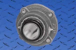
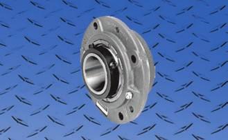
19 FLANGE BLOCKS GENERAL INFORMATION Flange blocks are well suited to thin wall mounting members. The only requirement for installation is that a hole be bored large enough to accept the shaft or collar. Mounting bolt holes are simply drilled into the framework. The flange block may be installed in any position. However, it has been designed for quick and easy vertical mounting. For Large Pilots, See Flange Cartridge Units on Page 23 Flange blocks are available with ³ ₁₆" flange pilot primarily for locating on mounting structure. It can also aid in reducing the shear stresses on the mounting bolts if there is proper fit up between the pilot and mounting structure. Points to consider in the Use of Flange Blocks: 1. In flange blocks, the flange and mounting bolts support the bearing, shaft, and all other forces that may be exerted upon the shaft. 2. Since the center of the bearing in a flange block projects beyond the flange, a bending movement may produce an additional load which must also be carried by the flange and mounting bolts. Proper fit up and tightening of mounting bolts is important to realize full housing strength. 3. Flange blocks are in their strongest position when the force is parallel with the shaft and in the direction of the base. ZB Flange Blocks - Normal Duty - Fixed ³ ₄" through 4" shaft sizes Shaft mounting styles 2000 series page series page series available, page series available, see page 41 ZEF Flange Blocks - Normal Duty - Fixed 1⁷ ₁₆" through 4" shaft sizes Shaft mounting styles 2000 series page series available, page series available, see page series available, see page 41 ZF/ZFS Flange Blocks - Heavy Duty Fixed & Expansion (uses ZMC cartridge page 29) 1⁷ ₁₆" through 5" shaft sizes Shaft mounting styles 5000 series, page series, page 22 Additional Information Housing Material Cast iron unless otherwise noted. Other materials available on special order. Bolt Holes - Cored ¹ ₃₂" larger than bolt diameters. Grease fittings ¹ ₈ NPT tapped holes with grease fittings thru size code 11, ¹ ₄ NPT above. Floating Blocks (expansion) For amount of axial movement see page 47. ZFS blocks use ZMC cartridge. 17

20 ZB FLANGE BLOCKS NORMAL DUTY 2000 Series Single Set Collar Side View Flange With Pilot Full Side View Flange Block Four Hole Round Flange Block Four Hole Square Flange Block Specifications Radial load ratings are shown on page 56 Shaft Complete Block No. Code Dimensions in B C D E G H L R S Bolts Req d. W Y No. Complete Block Net Wt. Lbs. ³ ₄ ZB ¹⁵ ₁₆ ZB ³⁷ ₆₄ 2⁹ ₁₆ 2¹⁵ ₁₆ ⁹ ₁₆ 5¹ ₈ ¹⁹ ₃₂ 1⁵ ₁₆ 2¹ ₁₆ 3 1³ ₄ ¹ ₁₆ 3 ³ ₈ ZB ¹ ₈ ZB ³ ₁₆ ZB ⁵⁷ ₆₄ 2¹¹ ₁₆ 3³ ₁₆ ⁹ ₁₆ 5¹ ₂ ⁵ ₈ 1¹⁷ ₃₂ 2¹ ₄ 3¹ ₄ 2 ¹ ₁₆ 3 ³ ₈ 5.1 1¹ ₄ ZB ⁷ ₁₆ ZB ²¹ ₆₄ 2⁷ ₈ 3⁷ ₁₆ ¹¹ ₁₆ 6¹ ₄ ²¹ ₃₂ 1³ ₄ 2¹ ₂ 3⁹ ₁₆ 2⁵ ₁₆ ¹ ₁₆ 3 ¹ ₂ 6.8 1¹ ₂ ZB ¹¹ ₁₆ 1³ ₄ ZB-2111 ZB ⁵⁷ ₆₄ 3¹ ₈ 3¹⁵ ₁₆ ¹¹ ₁₆ 6³ ₄ ²¹ ₃₂ 2¹ ₃₂ 2³ ₄ 4¹ ₁₆ 2⁵ ₈ ³ ₃₂ 4 ¹ ₂ ¹⁵ ₁₆ 2 ZB-2115 ZB ¹ ₁₆ 3¹ ₈ 4¹ ₄ ¹¹ ₁₆ 7 ¹¹ ₁₆ 2⁵ ₁₆ 2⁷ ₈ 4³ ₈ 2¹⁵ ₁₆ ³ ₃₂ 4 ¹ ₂ ³ ₁₆ ZB ¹ ₄ ZB ¹ ₂ 3⁵ ₁₆ 4⁷ ₈ ¹³ ₁₆ 7³ ₄ ¹¹ ₁₆ 2⁵ ₈ 3³ ₁₆ 5 3¹ ₄ ¹ ₈ 4 ⁵ ₈ ³ ₈ ZB ⁷ ₁₆ ZB ⁴⁹ ₆₄ 3¹ ₂ 5³ ₈ ⁷ ₈ 8¹ ₈ ³ ₄ 2²⁹ ₃₂ 3³ ₈ 5⁷ ₁₆ 3⁹ ₁₆ ¹ ₈ 4 ⁵ ₈ ¹ ₂ ZB ¹¹ ₁₆ ZB ³ ₄ 2¹⁵ ₁₆ ZB-2212 ZB ⁹ ₁₆ 4 6¹ ₄ ⁷ ₈ 9¹ ₂ ⁷ ₈ 3³ ₈ 3¹⁵ ₁₆ 6⁵ ₁₆ 4¹ ₁₆ ¹ ₈ 4 ³ ₄ ZB ³ ₁₆ ZB ⁷ ₁₆ ZB ²³ ₃₂ 4³ ₈ 7³ ₈ ¹⁵ ₁₆ 8⁷ ₁₆ 1 3³¹ ₃₂ 4³ ₄ 7³ ₈ 4¹⁵ ₁₆ ¹ ₄ 4 ³ ₄ ¹ ₂ ZB ¹¹ ₁₆ ZB ¹⁵ ₁₆ ZB ¹⁹ ₃₂ 5³ ₁₆ 8¹ ₂ 1¹ ₁₆ 9³ ₄ 1¹ ₈ 4⁹ ₁₆ 5³ ₈ 8¹ ₂ 5⁵ ₈ ¹ ₄ 4 ⁷ ₈ ZB Pilot - Use suffix S Bore = Nominal Shaft Metric Bore s Available - See Page 57 Seals - To specify K or M seal, replace Z in model number with K or M - See Pages 58 and 59. Auxiliary Caps - Not available in Codes 2-6, and Code 7 on flange side of non-piloted bearings Not available in Codes 2-6, and Codes 7-9 on flange side of piloted bearings Note: Dimensions subject to change. Certified dimensions of ordered material furnished on request. 18 OTHER SHAFT MOUNTING STYLES AVAILABLE. REFER TO PAGE 17.

21 ZB FLANGE BLOCKS TWIST LOCK MEDIUM DUTY 3000 Series Eccentric Lock Side View Flange With Pilot Full Side View Flange Block Four Hole Round Flange Block Four Hole Square Flange Block Specifications Radial load ratings are shown on page 56 Shaft Complete Block No. Code Dimensions in B C D E G H L R S Bolts Req d. W Y No. Net Wt. Lbs. 1⁷ ₁₆ ZB ²¹ ₆₄ 2⁵⁹ ₆₄ 3⁷ ₁₆ ²⁵ ₃₂ 6¹ ₄ ²¹ ₃₂ 1³ ₄ 2¹ ₂ 3⁹ ₁₆ 2⁵ ₁₆ ¹ ₁₆ 3 ¹ ₂ 7.0 1¹¹ ₁₆ ZB ⁵⁷ ₆₄ 3³ ₁₆ 3¹⁵ ₁₆ ³ ₄ 6³ ₄ ²¹ ₃₂ 2¹ ₃₂ 2³ ₄ 4¹ ₁₆ 2⁵ ₈ ³ ₃₂ 4 ¹ ₂ 8.8 1¹⁵ ₁₆ ZB ¹ ₁₆ 3⁹ ₃₂ 4¹ ₄ ²⁷ ₃₂ 7 ¹¹ ₁₆ 2⁵ ₁₆ 2⁷ ₈ 4³ ₈ 2³ ₄ ³ ₃₂ 4 ¹ ₂ ³ ₁₆ ZB ¹ ₂ 3¹ ₂ 4⁷ ₈ ³¹ ₃₂ 7³ ₄ ¹¹ ₁₆ 2⁵ ₈ 3³ ₁₆ 5 3¹ ₄ ¹ ₈ 4 ⁵ ₈ ⁷ ₁₆ ZB ¹ ₂ ZB ⁴⁹ ₆₄ 3²¹ ₃₂ 5³ ₈ 1¹ ₆₄ 8¹ ₈ ³ ₄ 2²⁹ ₃₂ 3³ ₈ 5⁷ ₁₆ 3⁹ ₁₆ ¹ ₈ 4 ⁵ ₈ ¹¹ ₁₆ ZB ¹⁵ ₁₆ ZB ⁹ ₁₆ 4¹³ ₆₄ 6¹ ₄ 1¹ ₆₄ 9¹ ₂ ⁷ ₈ 3³ ₈ 3¹⁵ ₁₆ 6⁵ ₁₆ 4¹ ₁₆ ¹ ₈ 4 ³ ₄ ⁷ ₁₆ ZB ¹ ₂ ZB ²³ ₃₂ 4³⁷ ₆₄ 7³ ₈ 1⁹ ₆₄ 8⁷ ₁₆ 1 3³¹ ₃₂ 4³ ₄ 7³ ₈ 4¹⁵ ₁₆ ¹ ₄ 4 ³ ₄ ¹⁵ ₁₆ ZB ¹⁹ ₃₂ 5³ ₁₆ 8¹ ₂ 1¹ ₁₆ 9³ ₄ 1¹ ₈ 4⁹ ₁₆ 5³ ₈ 8¹ ₂ 5⁵ ₈ ¹ ₄ 4 ⁷ ₈ 56.0 Pilot - Use suffix S Bore = Nominal Shaft Seals - To specify K or M seal, replace Z in model number with K or M - See Pages 58 and 59. Auxiliary Caps - Not available in Codes 4-6 and Code 7 on flange side of non-piloted bearings Not available in Codes 4-6 and Codes 7-9 on flange side of piloted bearings Note: Dimensions subject to change. Certified dimensions of ordered material furnished on request. OTHER SHAFT MOUNTING STYLES AVAILABLE. REFER TO PAGE

22 ZEF FLANGE BLOCKS NORMAL DUTY 2000 Series Single Set Collar Specifications Radial load ratings are shown on page 56 Shaft Complete Block No. Code Dimensions in Bolts Req d. B C D G H L R W Y No. Complete Block Net Wt. Lbs. 1⁷ ₁₆ ZEF ¹ ₂ 2⁷ ₈ 3¹¹ ₁₆ 4⁵ ₈ 1³ ₈ 1³ ₄ 2¹⁵ ₃₂ 2⁵ ₁₆ ¹ ₁₆ 4 ¹ ₂ 7.2 1¹ ₂ ZEF ¹ ₈ 2⁷ ₈ 4¹ ₄ 5³ ₈ 1⁷ ₁₆ 1³ ₄ 2⁵⁹ ₆₄ 2⁵ ₁₆ ¹ ₈ 4 ¹ ₂ ¹¹ ₁₆ ZEF ¹ ₈ 3¹ ₈ 4¹ ₄ 5³ ₈ 1⁷ ₁₆ 2¹ ₃₂ 2⁵⁹ ₆₄ 2⁵ ₈ ¹ ₈ 4 ¹ ₂ ³ ₄ ZEF ³ ₈ 3¹ ₈ 4¹ ₂ 5⁵ ₈ 1¹ ₂ 2¹ ₃₂ 3³ ₃₂ 2⁵ ₈ ¹ ₈ 4 ¹ ₂ ¹⁵ ₁₆ ZEF ³ ₈ 3¹ ₈ 4¹ ₂ 5⁵ ₈ 1¹ ₂ 2⁵ ₁₆ 3³ ₃₂ 2¹⁵ ₁₆ ¹ ₈ 4 ¹ ₂ ZEF ³ ₁₆ ZEF ⁷ ₈ 3⁵ ₁₆ 5 6¹ ₄ 1¹ ₂ 2⁵ ₈ 3²⁹ ₆₄ 3¹ ₄ ¹ ₈ 4 ⁵ ₈ ⁷ ₁₆ ZEF ³ ₈ 3¹ ₂ 5¹ ₂ 6⁷ ₈ 1¹¹ ₁₆ 2²⁹ ₃₂ 3⁵¹ ₆₄ 3⁹ ₁₆ ³ ₁₆ 4 ⁵ ₈ ¹ ₂ ZEF ¹¹ ₁₆ ZEF ³ ₄ 2¹⁵ ₁₆ ZEF-2212 ZEF ¹ ₂ 7³ ₄ 1¹³ ₁₆ 3³ ₈ 4¹ ₄ 4¹ ₁₆ ³ ₁₆ 4 ³ ₄ ZEF ³ ₁₆ ZEF ⁷ ₁₆ ZEF ³ ₈ 7³ ₈ 9¹ ₄ 1¹⁵ ₁₆ 3³¹ ₃₂ 4⁶¹ ₆₄ 4¹⁵ ₁₆ ¹ ₄ 4 ³ ₄ ¹ ₂ ZEF ¹¹ ₁₆ ZEF ¹⁵ ₁₆ ZEF ³ ₄ 5³ ₁₆ 8⁷ ₈ 10¹ ₄ 2³ ₁₆ 4⁹ ₁₆ 5³¹ ₆₄ 5⁵ ₈ ¹ ₄ 4 ⁷ ₈ ZEF Bore = Nominal Shaft Metric Bore s Available - See Page 57 Seals - To specify K or M seal, replace Z in model number with K or M - See Pages 58 and Series Twist Lock collar will be on side opposite the flange. Note: Dimensions subject to change. Certified dimensions of ordered material furnished on request. 20 OTHER SHAFT MOUNTING STYLES AVAILABLE. REFER TO PAGE 17.


23 ZF/ZFS FLANGE BLOCKS HEAVY DUTY 5000 Series Double Set Collar Fixed & Floating Side View Flange With Pilot Full Side View Flange Block Fixed Full Side View Flange Block Floating Four Hole Square Flange Block Six Hole Round Flange BLock Specifications Radial load ratings are shown on page 56 For available expansion see page 47 Shaft Complete Block No. Fixed Floating Code B C Fixed D Float. Dimensions in E E 1 G H R Fixed Float. S W Fixed Float. Bolts Req d. No. Fixed Complete Block Net Wt. Lbs. Float. 4-Bolt Square 1⁷ ₁₆ ZF-5107 ZFS ²³ ₃₂ 3⁹ ₁₆ 3¹¹ ₁₆ 4⁷ ₁₆ ¹¹ ₁₆ ¹⁵ ₃₂ ¹ ₂ 4¹⁵ ₁₆ ⁵ ₈ 2⁵ ₈ 3⁹ ₁₆ 4⁷ ₁₆ 2⁵ ₁₆ 4 ¹ ₂ ¹ ₂ ZF-5108 ZFS ⁵⁷ ₆₄ 3¹³ ₁₆ 4¹ ₄ 5 ²³ ₃₂ ¹³ ₃₂ ¹⁵ ₃₂ 5¹ ₈ ⁵ ₈ 2³ ₄ 4¹ ₁₆ 4³ ₄ 2⁵ ₈ 4 ¹ ₂ ¹¹ ₁₆ ZF-5111 ZFS ¹⁵ ₁₆ ZF-5115 ZFS ¹ ₁₆ 3¹³ ₁₆ 4¹ ₂ 5¹ ₈ ¹¹ ₁₆ ¹³ ₃₂ ¹⁵ ₃₂ 5⁵ ₁₆ ⁵ ₈ 2⁷ ₈ 4³ ₈ 5¹ ₈ 2¹⁵ ₁₆ 4 ¹ ₂ ZF-5200 ZFS ³ ₁₆ ZF-5203 ZFS ¹ ₂ 4¹ ₈ 5 5³ ₄ ⁵¹ ₆₄ ¹ ₂ ²¹ ₃₂ 5⁷ ₈ ¹¹ ₁₆ 3³ ₁₆ 5 5⁵ ₈ 3¹ ₄ 4 ⁵ ₈ ⁷ ₁₆ ZF-5207 ZFS ¹ ₃₂ 4³ ₈ 5¹ ₂ 6 ⁷ ₈ ⁹ ₁₆ ⁵ ₈ 6⁷ ₁₆ ³ ₄ 3⁹ ₁₆ 5⁷ ₁₆ 6 3⁹ ₁₆ 4 ⁵ ₈ ¹ ₂ ZF-5208 ZFS ¹¹ ₁₆ ZF-5211 ZFS ¹ ₆₄ 4⁷ ₈ 6¹ ₂ 7¹ ₈ ⁷ ₈ ⁵ ₈ ²¹ ₃₂ 7³ ₄ ⁷ ₈ 4¹ ₄ 6⁵ ₁₆ 7¹ ₈ 4¹ ₁₆ 4 ³ ₄ ¹⁵ ₁₆ ZF-5215 ZFS ³ ₁₆ ZF-5303 ZFS ²³ ₃₂ 5⁵ ₁₆ 7³ ₈ 8 ¹⁵ ₁₆ ⁹ ₁₆ ¹¹ ₁₆ 8⁷ ₁₆ 1 4³ ₄ 7³ ₈ 8 4¹⁵ ₁₆ 4 ³ ₄ ⁷ ₁₆ ZF-5307 ZFS ¹¹ ₁₆ ZF-5311 ZFS ¹⁵ ₁₆ ZF-5315 ZFS ⁵ ₁₆ 6¹ ₄ 8⁷ ₈ 9¹ ₂ 1¹ ₁₆ ¹¹ ₁₆ ¹³ ₁₆ 10⁹ ₁₆ 1¹ ₈ 5⁷ ₈ 8⁷ ₈ 9¹ ₂ 5⁵ ₈ ZF-5400 ZFS Bolt Round, (Holes at 60.) 4³ ₁₆ ZF-5403Y ZFS-5403Y ⁷ ₁₆ ZF-5407Y ZFS-5407Y 12 6⁷ ₁₆ 6¹ ₄ 9¹ ₂ 11⁵ ₈ 1 ¹¹ ₁₆ ³ ₄ 15¹ ₈ 1¹ ₄ 6⁷ ₁₆ 10³ ₈ 11⁵ ₈ 6³ ₁₆ ¹ ₂ ZF-5408Y ZFS-5408Y ¹⁵ ₁₆ ZF ZF ¹ ₈ ¹⁵ ₁₆... ZFS ⁷ ₈ 11³ ₁₆ 12⁹ ₁₆ 1³ ₁₆ ²³ ₃₂ ³ ₄ 16¹ ₂ 1¹ ₂ 7 11³ ₁₆ 12⁹ ₁₆ 7¹ ₁₆ ZFS Pilot - Use suffix S Bore = Nominal Shaft Metric Bore s Available - See Page 57 Seals - To specify K or M seal, replace Z in model number with K or M - See Pages 58 and 59. Auxiliary Caps - Not available in Code 12 ZFS bearings. Also not available in Codes 4-6 on flange side of piloted bearings. Note: Dimensions subject to change. Certified dimensions of ordered material furnished on request. OTHER SHAFT MOUNTING STYLES AVAILABLE. REFER TO PAGE


24 ZF/ZFS FLANGE BLOCKS ADAPTER 9000 Series Fixed and Floating Side View Flange With Pilot Full Side View Flange Block Fixed Full Side View Flange Block Floating Four Hole Square Flange Block Six Hole Round Flange BLock Specifications Radial load ratings are shown on page 56 For available expansion see page 47 Shaft Complete Block No. Fixed Floating Code B Dimensions in C D E G H R Fixed Float. Fixed Float. Fixed Float. S W Fixed Float. Y Fixed Float. Complete Bolt Block Net Wt. Lbs. Fixed Float. 4 Bolt Square 1¹⁵ ₁₆ ZF-9115 ZFS ZF-9200 ZFS ¹ ₂ 3¹ ₄ 3⁷ ₁₆ 5 5³ ₄ ⁹ ₁₆ ⁵ ₁₆ 5⁷ ₈ ¹¹ ₁₆ 3³ ₁₆ 5 5⁵ ₈ 2³¹ ₃₂ ¹¹ ₆₄ ⁵ ₁₆ ⁵ ₈ ³ ₁₆ ZF-9203 ZFS ¹ ₃₂ 3¹⁹ ₃₂ 3²¹ ₃₂ 5¹ ₂ 6 ²³ ₃₂ ¹¹ ₃₂ 6⁷ ₁₆ ³ ₄ 3⁹ ₁₆ 5⁷ ₁₆ 6 3³ ₈ ¹ ₄ ⁵ ₁₆ ⁵ ₈ ⁷ ₁₆ ZF-9207 ZFS ¹ ₆₄ 4³ ₃₂ 4³ ₃₂ 6¹ ₂ 7¹ ₈ ²³ ₃₂ ¹⁵ ₃₂ 7³ ₄ ⁷ ₈ 4¹ ₄ 6⁵ ₁₆ 7¹ ₈ 3⁵ ₈ ¹⁵ ₆₄ ¹ ₄ ³ ₄ ¹ ₂ ZF-9208 ZFS ¹¹ ₁₆ ZF-9211 ZFS ¹⁵ ₁₆ ZF-9215 ZFS ²³ ₃₂ 4¹ ₂ 4⁵ ₈ 7³ ₈ 8 ¹³ ₁₆ ⁷ ₁₆ 8⁷ ₁₆ 1 4³ ₄ 7³ ₈ 8 4¹³ ₃₂ ¹ ₄ ³ ₈ ³ ₄ ZF-9300 ZFS ³ ₁₆ ZF-9303 ZFS ⁵ ₁₆ 5⁵ ₁₆ 5⁷ ₁₆ 8⁷ ₈ 9¹ ₂ ¹⁵ ₁₆ ⁹ ₁₆ 10⁹ ₁₆ 1¹ ₈ 5⁷ ₈ 8⁷ ₈ 9¹ ₂ 5³ ₁₆ ¹ ₄ ³ ₈ ⁷ ₁₆ ZF-9307 ZFS Bolt Round, (Holes at 60.) 3¹¹ ₁₆ ZF-9311Y ZFS-9311Y ¹⁵ ₁₆ ZF-9315Y ZFS-9315Y 12 6⁷ ₁₆ 5¹⁷ ₃₂ 5¹⁹ ₃₂ 9¹ ₂ 11⁵ ₈ 1¹ ₃₂ ²³ ₃₂ 15¹ ₈ 1¹ ₄ 6⁷ ₁₆ 10³ ₈ 11⁵ ₈ 5²³ ₃₂ ¹ ₈ ³ ₁₆ ZF-9400Y ZFS-9400Y ³ ₁₆ ZF ⁷ ₁₆ ZF ¹ ₈ ¹ ₃₂ 7¹ ₁₆ 11³ ₁₆ 12⁹ ₁₆ 1¹ ₁₆ ⁵ ₈ 16¹ ₂ 1¹ ₂ 7 11³ ₁₆ 12⁹ ₁₆ 6¹ ₈ ⁹ ₃₂ ⁵ ₁₆ ³ ₁₆... ZFS ⁷ ₁₆... ZFS Pilot - Use suffix S Bore = Nominal Shaft Metric Bore s Available - See Page 57 Seals - To specify K or M seal, replace Z in model number with K or M - See Pages 58 and 59. Auxiliary Caps - Not available in Code 12 ZFS bearings. Note: Dimensions subject to change. Certified dimensions of ordered material furnished on request. OTHER SHAFT MOUNTING STYLES AVAILABLE. REFER TO PAGE

25 ZBR FLANGE CARTRIDGE BLOCKS GENERAL INFORMATION The flange cartridge block, while similar to flange blocks, has its greatest application in machines where the bulk of the housing is buried in the structural members. It is applied to its best advantage when mounted in a cast iron or steel base such as on compactors, machine tools, grinders, etc. Unlike the flange block which is supported by mounting bolts, the flange cartridge block is supported entirely on the pilot of the block. The function of the mounting bolts is merely to stabilize the unit. Points to consider in the use of flange cartridge blocks: 1. A flange cartridge block is designed to have its mounting base perpendicular to the shaft. 2. Flange cartridge blocks rank very high in housing strength because loads are transmitted from the cartridge to the wall of the mounting support member. 3. Flange cartridge blocks are in their strongest position when the force is perpendicular to the shaft and in the direction of the cartridge O.D. ZBR Flange Cartridge Blocks 2000 Series Single Set Collar ³ ₄" through 4" shaft sizes page Series Twist Lock 1⁷ ₁₆" through 3¹⁵ ₁₆" shaft sizes Eccentric Locking Collar page Series Double Set Collar 1⁷ ₁₆" through 7" shaft sizes page Series Tapered Adapter Sleeve 1¹⁵ ₁₆" through 6⁷ ₁₆" shaft sizes page 41 Note: All ZBR Flange Cartridges are supplied with jack screw holes for easy removal. Additional Information Housing Material - Cast iron unless otherwise noted. Other materials available on special order. Bolt Holes - Drilled ¹ ₃₂" larger than bolt diameters. Grease fittings ¹ ₈ NPT tapped holes with grease fittings thru size code 11, ¹ ₄ NPT above. Mounting Bore Diameter from Maximum S" dimension is recommended. 23
26 ZBR FLANGE CARTRIDGE BLOCKS NORMAL DUTY 2000 Series Single Set Collar 3 JACKSCREW HOLES PROVIDED Shaft Complete Block No. Code B Specifications Radial load ratings are shown on page 56 C E F H Dimensions in M N R S ³ ₄ ZBR ¹⁵ ₁₆ ZBR ⁹ ₁₆ 2⁹ ₁₆ ⁹ ₁₆ 4³ ₈ ⁷ ₁₆ 1⁵ ₁₆ ⁵ ₈ 1¹³ ₁₆ ³ ₄ 1¹ ₄ ⁵ ₁₆ ZBR ¹ ₈ ZBR ³ ₁₆ ZBR ⁵⁹ ₆₄ 2¹¹ ₁₆ ⁹ ₁₆ 5 ⁷ ₁₆ 1⁵ ₁₆ ³ ₄ 2¹ ₁₆ ³ ₈ ³ ₈ 4.8 1¹ ₄ ZBR ⁷ ₁₆ ZBR ³ ₃₂ 2⁷ ₈ ¹¹ ₁₆ 5¹ ₄ ¹ ₂ 1¹ ₂ ³ ₄ 2³ ₁₆ ⁵ ₁₆ 1³ ₈ ³ ₈ 5.4 1¹ ₂ ZBR ¹¹ ₁₆ ZBR ³ ₄ ZBR ⁵ ₈ 3¹ ₈ ¹¹ ₁₆ 6¹ ₈ ¹ ₂ 1¹⁹ ₃₂ ⁷ ₈ 2⁹ ₁₆ ⁵ ₈ 1¹⁷ ₃₂ ⁷ ₁₆ 8.1 1¹⁵ ₁₆ ZBR ZBR ⁵¹ ₆₄ 3¹ ₈ ¹¹ ₁₆ 6³ ₈ ⁹ ₁₆ 1⁹ ₁₆ ⁷ ₈ 2¹¹ ₁₆ ¹⁵ ₁₆ 1⁹ ₁₆ ⁷ ₁₆ 8.7 2³ ₁₆ ZBR ¹ ₄ 3⁵ ₁₆ ¹³ ₁₆ 7¹ ₈ ⁹ ₁₆ 1³ ₄ ¹ ₄ 1⁹ ₁₆ ¹ ₂ ¹ ₄ ZBR ³ ₈ ZBR ⁷ ₁₆ ZBR ¹⁹ ₃₂ 3¹ ₂ ⁷ ₈ 7⁵ ₈ ⁵ ₈ 1¹³ ₁₆ 1 3¹ ₄ ⁹ ₁₆ 1¹¹ ₁₆ ¹ ₂ ¹ ₂ ZBR ¹¹ ₁₆ ZBR ³ ₄ ZBR ¹⁵ ₁₆ ZBR ¹⁹ ₆₄ 4 ⁷ ₈ 8³ ₄ ³ ₄ 2 1¹ ₄ 3³ ₄ ¹ ₁₆ 2 ⁵ ₈ ZBR ³ ₁₆ ZBR ⁷ ₁₆ ZBR ³ ₃₂ 4³ ₈ ¹⁵ ₁₆ 10¹ ₄ ¹⁵ ₁₆ 2³ ₈ 1¹ ₄ 4⁵ ₁₆ ¹⁵ ₁₆ 2 ³ ₄ ¹ ₂ ZBR ¹¹ ₁₆ ZBR ¹⁵ ₁₆ ZBR ⁵ ₈ 5³ ₁₆ 1¹ ₁₆ 10⁷ ₈ 1¹ ₈ 2¹¹ ₁₆ 1¹ ₂ 4¹¹ ₁₆ ⁵ ₈ 2¹ ₂ ³ ₄ ZBR Bore = Nominal Shaft Metric Bore s Available - See Page 57 Seals - To specify K or M seal, replace Z in model number with K or M - See Pages 58 and 59. Auxiliary Caps - Not available in Codes 2 & 3 W Y Flange I.R. End Bolt Complete Block Net Wt. Lbs. Note: Dimensions subject to change. Certified dimensions of ordered material furnished on request. OTHER SHAFT MOUNTING STYLES AVAILABLE. REFER TO PAGE

27 ZBR FLANGE CARTRIDGE BLOCKS TWIST LOCK MEDIUM DUTY 3000 Series Eccentric Lock 3 JACKSCREW HOLES PROVIDED Shaft Complete Block No. Code B Specifications Radial load ratings are shown on page 51 C E F H Dimensions in M N R S ⁷ ₁₆ ZBR ³ ₃₂ 2⁵⁹ ₆₄ ²⁵ ₃₂ 5¹ ₄ ¹ ₂ 1¹ ₂ ³ ₄ 2³ ₁₆ ⁵ ₁₆ 1³ ₈ ³ ₈ 5.6 1¹¹ ₁₆ ZBR ⁵ ₈ 3³ ₁₆ ³ ₄ 6¹ ₈ ¹ ₂ 1¹⁹ ₃₂ ⁷ ₈ 2⁹ ₁₆ ⁵ ₈ 1¹⁷ ₃₂ ⁷ ₁₆ 8.6 1¹⁵ ₁₆ ZBR ⁵¹ ₆₄ 3⁹ ₃₂ ²⁷ ₃₂ 6³ ₈ ⁹ ₁₆ 1²³ ₃₂ ⁷ ₈ 2¹¹ ₁₆ ¹⁵ ₁₆ 1⁹ ₁₆ ⁷ ₁₆ 9.0 2³ ₁₆ ZBR ¹ ₄ 3¹ ₂ ³¹ ₃₂ 7¹ ₈ ⁹ ₁₆ 1¹⁵ ₁₆ ¹ ₄ 1⁹ ₁₆ ¹ ₂ ⁷ ₁₆ ZBR ¹ ₂ ZBR ¹⁹ ₃₂ 3²¹ ₃₂ 1¹ ₆₄ 7⁵ ₈ ⁵ ₈ 1³¹ ₃₂ 1 3¹ ₄ ⁹ ₁₆ 1¹¹ ₁₆ ¹ ₂ ¹¹ ₁₆ ZBR ¹⁵ ₁₆ ZBR ¹⁹ ₆₄ 4¹³ ₆₄ 1¹ ₆₄ 8³ ₄ ³ ₄ 2¹³ ₆₄ 1¹ ₄ 3³ ₄ ¹ ₁₆ 2 ⁵ ₈ ⁷ ₁₆ ZBR-3307 ³ ₄ ¹ ₂ ZBR ³ ₃₂ 4³⁷ ₆₄ 1⁹ ₆₄ 10¹ ₄ ¹⁵ ₁₆ 2³⁷ ₆₄ 1¹ ₄ 4⁵ ₁₆ ¹⁵ ₁₆ ¹⁵ ₁₆ ZBR ⁵ ₈ 5³ ₁₆ 1¹ ₁₆ 10⁷ ₈ 1¹ ₈ 2¹¹ ₁₆ 1¹ ₂ 4¹¹ ₁₆ ⁵ ₈ 2¹ ₂ ³ ₄ 49.0 Bore = Nominal Shaft Seals - To specify K or M seal, replace Z in model number with K or M. See pages 58 and 59. W Y Flange I.R. End Bolt Net Wt. Lbs. Note: Dimensions subject to change. Certified dimensions of ordered material furnished on request. OTHER SHAFT MOUNTING STYLES AVAILABLE. REFER TO PAGE
28 ZBR FLANGE CARTRIDGE BLOCKS HEAVY DUTY 5000 Series Double Set Collar 3 JACKSCREW HOLES PROVIDED Specifications Radial load ratings are shown on page 56 Shaft Complete Block No. Codes B Dimensions in Bolts Req d. C E F H M N R S W Y No. Complete Block Net Wt. Lbs. 1⁷ ₁₆ ZBR ³ ₃₂ 3⁹ ₁₆ ¹¹ ₁₆ 5¹ ₄ ¹ ₂ 1¹ ₂ ³ ₄ 2³ ₁₆ ⁵ ₁₆ 2¹ ₁₆ 4 ³ ₈ 5.9 1¹ ₂ ZBR ⁵ ₈ 3¹³ ₁₆ ¹¹ ₁₆ 6¹ ₈ ¹ ₂ 1¹⁹ ₃₂ ⁷ ₈ 2⁹ ₁₆ ⁵ ₈ 2⁷ ₃₂ 4 ⁷ ₁₆ 9.1 1¹¹ ₁₆ ZBR ¹⁵ ₁₆ ZBR ⁵¹ ₆₄ 3¹³ ₁₆ ¹¹ ₁₆ 6³ ₈ ⁹ ₁₆ 1⁹ ₁₆ ⁷ ₈ 2¹¹ ₁₆ ¹⁵ ₁₆ 2¹ ₄ 4 ⁷ ₁₆ ZBR ³ ₁₆ ZBR ¹ ₄ 4¹ ₈ ¹³ ₁₆ 7¹ ₈ ⁹ ₁₆ 1³ ₄ ¹ ₄ 2³ ₈ 4 ¹ ₂ ⁷ ₁₆ ZBR ¹⁹ ₃₂ 4³ ₈ ⁷ ₈ 7⁵ ₈ ⁵ ₈ 1¹³ ₁₆ 1 3¹ ₄ ⁹ ₁₆ 2⁹ ₁₆ 4 ¹ ₂ ¹ ₂ ZBR ¹¹ ₁₆ ZBR ¹⁹ ₆₄ 4⁷ ₈ ⁷ ₈ 8³ ₄ ³ ₄ 2 1¹ ₄ 3³ ₄ ¹ ₁₆ 2⁷ ₈ 4 ⁵ ₈ ¹⁵ ₁₆ ZBR ³ ₁₆ ZBR ³ ₃₂ 5⁵ ₁₆ ¹⁵ ₁₆ 10¹ ₄ ¹⁵ ₁₆ 2³ ₈ 1¹ ₄ 4⁵ ₁₆ ¹⁵ ₁₆ 2¹⁵ ₁₆ 4 ³ ₄ ⁷ ₁₆ ZBR ¹¹ ₁₆ ZBR ¹⁵ ₁₆ ZBR ⁵ ₈ 6¹ ₄ 1¹ ₁₆ 10⁷ ₈ 1¹ ₈ 2¹¹ ₁₆ 1¹ ₂ 4¹¹ ₁₆ ⁵ ₈ 3⁹ ₁₆ 4 ³ ₄ ZBR ⁷ ₁₆ ZBR-5407Y 12 5⁷ ₈ 6¹ ₄ 1 13¹ ₂ 1 2⁵ ₁₆ 2 5⁷ ₈ ³ ₁₆ 3¹⁵ ₁₆ 6 ³ ₄ ¹ ₂ ZBR-5408Y ¹⁵ ₁₆ ZBR ZBR ³ ₈ 7⁷ ₈ 1⁵ ₃₂ 14³ ₄ 1¹ ₄ 2³¹ ₃₂ 2¹ ₄ 6³ ₈ ¹ ₁₆ 4²⁹ ₃₂ 6 ⁷ ₈ ⁷ ₁₆ ZBR ¹ ₄ 8 1⁷ ₃₂ 17 1³ ₈ 3⁷ ₃₂ 2 7¹ ₄ ³ ₁₆ 4²⁵ ₃₂ 6 ⁷ ₈ ¹⁵ ₁₆ ZBR ¹ ₄ 8¹ ₈ 1⁵ ₃₂ ¹ ₁₆ 1³ ₈ 8¹ ₄ ¹¹ ₁₆ 5¹ ₁₆ 6 ⁷ ₈ ZBR ⁷ ₁₆ ZBR ¹⁵ ₁₆ ZBR ¹ ₂ 8³ ₄ 1⁹ ₃₂ ³ ₈ 1¹ ₂ 8¹ ₂ ³ ₄ 5³ ₈ ZBR Bore = Normal Shaft Metric Bore s Available - See Page 57 Seals - To specify K or M seal, replace Z in model number with K or M - See Pages 58 and 59. Outside Diameter Tolerance: Codes 4-13 = +.000,-.002 and Codes = +.000,-.005 Note: Dimensions subject to change. Certified dimensions of ordered material furnished on request. OTHER SHAFT MOUNTING STYLES AVAILABLE. REFER TO PAGE


29 CARTRIDGE BLOCKS GENERAL INFORMATION Unlike naked bearings, Rex cartridge blocks come completely factory assembled, adjusted, lubricated, and sealed against contamination. They provide a simple method for securing the bearing to the shaft. The cartridge block presents a real opportunity to the imaginative designer as it can be mounted in any type of equipment that has a thick wall support member. For example, it can be used where special, costly housings would normally be necessary. This means not only important initial savings, but also savings over the expensive replacement of special housings. Cartridge blocks may be adapted to particular needs by the use of a fabricated base which is cut to the desired contour and then simply bored - with the cartridge then added to this assembly. Points to consider when using cartridge blocks: 1. A means must be provided for locking the cartridge in the mounting structure to prevent lateral movement. Dog point set screws that protrude into the counterbored holes in the housing are good means of locking. 2. Provision for relubrication must be made. Often, locking and relubrication can be combined with a common fitting. A special locking pin which allows this is provided with the ZCS series. 3. Cartridge blocks are in the strongest position when the force is perpendicular to the shaft and stationary relative to the cartridge outside diameter. ZMC Thick Wall Cast Type ³ ₄" through 7" shaft sizes Shaft mounting styles 2000 series page series available, page series, page series, see page 30 ZCS Thin Wall Steel Type 1⁷ ₁₆" through 4" shaft sizes Shaft mounting styles 2000 series page series available, page series, page series, see page 41 Additional Information Housing Material - Cast iron for ZMC, Steel for ZCS. Other materials available on special order. Grease fittings ¹ ₈" NPT tapped holes with grease fittings thru size code 11, ¹ ₄" NPT above. Floating Unit Design - Cartridge blocks may be installed as floating or expansion units. See page 47 for available movement. 27


30 ZCS CARTRIDGE BLOCKS NORMAL DUTY 2000 Series Single Set Collar HEAVY DUTY 5000 Series Double Set Collar MAY BE USED AS FIXED OR FLOATING* DESIGN NORMAL DUTY 2000 Series HEAVY DUTY 5000 Series Specifications Radial load ratings are shown on page 56 Shaft Complete Block No Series 5000 Series Code 2000 Series C 5000 Series Dimensions in G J K L S W 2000 Series Complete Block Net Wt., Lbs Series 1⁷ ₁₆ ZCS-2107 ZCS ¹ ₂ ZCS ⁷ ₈ 3⁹ ₁₆ ⁵ ₁₆ 2.8 1¹ ₂ ZCS ¹¹ ₁₆ ZCS-2111 ZCS ¹ ₈ 3¹³ ₁₆ ⁵ ₈ ³ ₄ ZCS ¹⁵ ₁₆ ZCS-2115 ZCS ZCS ¹ ₈ 3¹³ ₁₆ ¹⁵ ₁₆ ZCS ³ ₁₆ ZCS-2203 ZCS ⁵ ₁₆ 4¹ ₈ ¹ ₄ ¹ ₄ ZCS ³ ₈ ZCS ⁷ ₁₆ ZCS-2207 ZCS ¹ ₂ 4³ ₈ ⁹ ₁₆ ¹ ₂ ZCS ¹ ₂ ZCS ¹¹ ₁₆ ZCS-2211 ZCS ³ ₄ ZCS ⁷ ₈ ¹ ₁₆ ¹⁵ ₁₆ ZCS-2215 ZCS ZCS ³ ₁₆ ZCS-2303 ZCS ⁷ ₁₆ ZCS-2307 ZCS ³ ₈ 5⁵ ₁₆ ¹⁵ ₁₆ ¹ ₂ ZCS ¹¹ ₁₆ ZCS-2311 ZCS ¹⁵ ₁₆ ZCS-2315 ZCS ³ ₁₆ 6¹ ₄ ⁵ ₈ ZCS-2400 ZCS Bore = Nominal Shaft Metric Bore s Available - See Page 57 Seals - To specify K or M seal, replace Z in model number with K or M - See Pages 58 and 59. Auxiliary Caps - Not available in ZCS Series * Expansion slot allows 3/8" float A locking pin and grease fitting is supplied with each unit as a means to lubricate and secure the bearing. Recommended engagement of the locking pin into the cartridge slot is.125" +/-.015" 3/4 HEX / Note: Dimensions subject to change. Certified dimensions of ordered material furnished on request. OTHER SHAFT MOUNTING STYLES AVAILABLE. REFER TO PAGE 27. LOCKING PIN

31 ZMC CARTRIDGE BLOCKS NORMAL DUTY 2000 Series Single Set Collar HEAVY DUTY 5000 Series Double Set Collar NORMAL DUTY 2000 Series HEAVY DUTY 5000 Series Shaft Complete Block No Series Specifications Radial load ratings are shown on page 56 For available float see page Series Code 2000 Series C 5000 Series G Dimensions in X Slot Dimensions G 1 S Length Width Depth W Y 2000 Series Complete Block Net Wt., Lbs. ³ ₄ ZMC ¹⁵ ₁₆ ZMC ⁹ ₁₆ ³ ₄ ZMC ¹ ₈ ZMC ³ ₁₆ ZMC ¹¹ ₁₆ 2¹ ₈ ¹ ₄ ZMC ⁷ ₁₆ ZMC-2107 ZMC ¹ ₂ ZMC ⁷ ₈ 3⁹ ₁₆ 2³ ₁₆ ²⁹ ₃₂.531 ³ ₁₆ 2⁵ ₁₆ 3.8 1¹ ₂ ZMC ¹¹ ₁₆ ZMC-2111 ZMC ¹ ₈ 3¹³ ₁₆ 2⁷ ₁₆ ²⁹ ₃₂.531 ³ ₁₆ 2⁵ ₈ ³ ₄ ZMC ¹⁵ ₁₆ ZMC-2115 ZMC ZMC ¹ ₈ 3¹³ ₁₆ 2⁷ ₁₆ ²⁹ ₃₂.531 ³ ₁₆ 2¹⁵ ₁₆ ZMC ³ ₁₆ ZMC-2203 ZMC ⁵ ₁₆ 4¹ ₈ 2⁹ ₁₆ ²⁹ ₃₂.531 ³ ₁₆ 3¹ ₄ ¹ ₄ ZMC ³ ₈ ZMC ⁷ ₁₆ ZMC-2207 ZMC ¹ ₂ 4³ ₈ 2⁵ ₈ ²⁹ ₃₂.531 ³ ₁₆ 3⁹ ₁₆ ¹ ₂ ZMC ¹ ₂ ZMC ¹¹ ₁₆ ZMC-2211 ZMC ³ ₄ ZMC ⁷ ₈ 3¹ ₈ ¹ ₃₂.594 ¹ ₄ 4¹ ₁₆ ¹⁵ ₁₆ ZMC-2215 ZMC ZMC ³ ₁₆ ZMC-2303 ZMC ⁷ ₁₆ ZMC-2307 ZMC ³ ₈ 5⁵ ₁₆ 3⁷ ₁₆ ¹ ₁₆.594 ⁹ ₃₂ 4¹⁵ ₁₆ ¹ ₂ ZMC ¹¹ ₁₆ ZMC-2311 ZMC ¹⁵ ₁₆ ZMC-2315 ZMC ³ ₁₆ 6¹ ₄ 4¹ ₈ ⁹ ₃₂.781 ⁵ ₁₆ 5⁵ ₈ ZMC-2400 ZMC ³ ₁₆ ZMC-5403Y ⁷ ₁₆ ZMC-5407Y 12 6¹ ₄ 4¹ ₄ ¹ ₂.781 ⁵ ₁₆ 6³ ₁₆ ¹ ₂ ZMC-5408Y ¹⁵ ₁₆ ZMC ⁷ ₈ 5⁹ ₁₆ ¹ ₂.781 ⁵ ₁₆ 7¹ ₁₆ 7²⁵ ₃₂ ZMC ⁷ ₁₆ ZMC ⁹ ₁₆ 5⁷ ₈ ¹ ₂.781 ⁷ ₃₂ 8³ ₁₆ 9⁹ ₁₆ ¹⁵ ₁₆ ZMC ZMC ¹ ₈ 5⁷ ₈ 6¹ ₈ ¹ ₂.781 ⁷ ₃₂ 8²¹ ₃₂ 10³ ₈ ⁷ ₁₆ ZMC ¹⁵ ₁₆ ZMC ³ ₄ 6³ ₁₆ 6¹ ₂ ¹ ₂.781 ⁷ ₃₂ 9²³ ₃₂ 11³ ₈ ZMC Bore = Nominal Shaft Metric Bore s Available - See Page 57 Seals - To specify K or M seal, replace Z in model number with K or M - See Pages 58 and 59. Auxiliary Caps - Not available in ZMC Series Outside Diameter Tolerance: Code 2-11 = +.000, and Code = +.000, Note: Dimensions subject to change. Certified dimensions of ordered material furnished on request. OTHER SHAFT MOUNTING STYLES AVAILABLE. REFER TO PAGE Series 29


32 ZMC CARTRIDGE BLOCKS ADAPTER 9000 Series Specifications Radial load ratings are shown on page 56 For available float see page 47 Dimensions in Shaft Complete Complete Block X Slot Dimensions Block Code No. C G G 1 S Width W Y Net Wt. Length Depth Lbs ¹⁵ ₁₆ ZMC ⁵ ₃₂ 2⁹ ₁₆ ²⁹ ₃₂.531 ³ ₁₆ 2³¹ ₃₂ ZMC ³ ₁₆ ZMC ¹¹ ₃₂ 2⁵ ₈ ²⁹ ₃₂.531 ³ ₁₆ 3³ ₈ 9.6 2⁷ ₁₆ ZMC ¹ ₂ ZMC ²⁷ ₃₂ 3¹ ₈ ¹ ₃₂.594 ¹ ₄ 3⁵ ₈ ¹¹ ₁₆ ZMC ¹⁵ ₁₆ ZMC ¹ ₄ 3⁷ ₁₆ ¹ ₁₆.594 ⁹ ₃₂ 4¹³ ₃₂ ZMC ³ ₁₆ ZMC ⁷ ₁₆ ZMC ³ ₃₂ 4¹ ₈ ⁹ ₃₂.781 ⁵ ₁₆ 5³ ₁₆ ¹¹ ₁₆ ZMC-9311Y ¹⁵ ₁₆ ZMC-9315Y 12 5¹³ ₃₂ 4¹ ₄ ¹ ₂.781 ⁵ ₁₆ 5²³ ₃₂ ZMC-9400Y ³ ₁₆ ZMC ⁷ ₁₆ ZMC ¹³ ₁₆ 5⁹ ₁₆ ¹ ₂.781 ⁵ ₁₆ 6¹ ₈ 7²⁵ ₃₂ ¹⁵ ₁₆ ZMC ³ ₁₆ 5⁹ ₁₆ 5⁷ ₈ ¹ ₂.781 ⁷ ₃₂ 7³ ₃₂ 9⁹ ₁₆ ZMC ⁷ ₁₆ ZMC ⁷ ₁₆ 5⁷ ₈ 6¹ ₈ ¹ ₂.781 ⁷ ₃₂ 8¹ ₁₆ 10³ ₈ ¹⁵ ₁₆ ZMC ZMC ³ ₄ 6³ ₁₆ 6¹ ₂ ¹ ₂.781 ⁷ ₃₂ 9¹ ₁₆ 11³ ₈ ⁷ ₁₆ ZMC Bore = Nominal Shaft Metric Bore s Available - See Page 57 Seals - To specify K or M seal, replace Z in model number with K or M - See Pages 58 and 59. Auxiliary Caps - Not available in ZMC Series Outside Diameter Tolerance: Code 2-11 = +.000, and Code = +.000, Note: Dimensions subject to change. Certified dimensions of ordered material furnished on request. OTHER SHAFT MOUNTING STYLES AVAILABLE. REFER TO PAGE


33 ZD DUPLEX UNITS GENERAL INFORMATION These units consist of bearing assemblies with mounting covers, seals and adjustment shims. They also include a simple method for securing the bearing to the shaft. Though similar to cartridge blocks, the bearing O.D. of duplex units determines the size of the mounting hole bore dimension, therefore requiring less space. Cover plates secure the bearing in the mounting. Points to consider in the use of duplex units: 1. Provision must be made for lubrication. 2. Duplex units require a close tolerance mounting bore and mounting wall dimensions. 3. Duplex units are in the strongest position when the force is perpendicular to the shaft. ZD Duplex Unit 1⁷ ₁₆" through 4" shaft sizes Shaft mounting styles 2000 series page series available, page series, page series available, see page 41 Normal Duty 2000 Series Heavy Duty 5000 Series Additional Information Housing Material - Cast iron unless otherwise noted. Other materials available on special order. Grease fittings - Customer devises lubrication method and fittings. Bolt Holes - Drilled ¹ ₃₂" larger than cap screw diameters listed in Specification tables. Lubrication - Bearings supplied with protective coating, see INSTRUCTION TAG, which is packaged with each unit. Shims - Furnished with each unit. Packaging - Units are usually stocked and shipped in separate cartons. Therefore a ZD2107 unit may be shipped as a 2107U bearing replacement kit and a ZD-4 kit. 31

34 ZD DUPLEX UNITS NORMAL DUTY 2000 Series Single Set Collar HEAVY DUTY 5000 Series Double Set Collar Shaft Complete Unit No Series 5000 Series Code B Specifications Radial load ratings are shown on page 56 Series E G G 1 H L N R 1⁷ ₁₆ ZD-2107 ZD ¹ ₂ ZD ⁹ ₁₆ 2⁷ ₈ 3⁹ ₁₆ ⁵ ₈ 3⁵ ₁₆ 3³ ₄ ⁵ ₁₆ 1³ ₄ ⁷ ₃₂ 1¹³ ₁₆ ³ ₈ 2⁵ ₁₆ ¹ ₂ ZD ¹¹ ₁₆ ZD-2111 ZD ⁷ ₈ 3¹ ₈ 3¹³ ₁₆ ⁵ ₈ 3³ ₄ 4¹ ₄ ⁵ ₁₆ 2¹ ₃₂ ³ ₁₆ 2¹ ₃₂ ³ ₈ 2⁵ ₈ ³ ₄ ZD ¹⁵ ₁₆ ZD-2115 ZD ZD ¹ ₈ 3¹³ ₁₆ ²¹ ₃₂ 4 4¹ ₂ ⁵ ₁₆ 2⁵ ₁₆ ³ ₁₆ 2¹ ₈ ³ ₈ 2¹⁵ ₁₆ ZD ³ ₁₆ ZD-2203 ZD ¹³ ₃₂ 3⁵ ₁₆ 4¹ ₈ ¹¹ ₁₆ 4⁹ ₁₆ 5¹ ₈ ⁵ ₁₆ 2⁵ ₈ ¹ ₈ 2¹³ ₃₂ ⁷ ₁₆ 3¹ ₄ ¹ ₄ ZD ³ ₈ ZD ⁷ ₁₆ ZD-2207 ZD ²³ ₃₂ 3¹ ₂ 4³ ₈ ³ ₄ 4¹⁵ ₁₆ 5¹ ₂ ⁵ ₁₆ 2²⁹ ₃₂ ¹ ₄ 2⁵ ₈ ¹ ₂ 3⁹ ₁₆ ¹ ₂ ZD ¹ ₂ ZD ¹¹ ₁₆ ZD-2211 ZD ³ ₄ ZD ²¹ ₆₄ 4 4⁷ ₈ ³ ₄ 6 6¹ ₂ ³ ₈ 3³ ₈ ¹ ₄ 3¹ ₁₆ ¹ ₂ 4¹ ₁₆ ¹⁵ ₁₆ ZD-2215 ZD ZD ³ ₁₆ ZD-2303 ZD ⁷ ₁₆ ZD-2307 ZD ⁶¹ ₆₄ 4³ ₈ 5⁵ ₁₆ ⁷ ₈ 6¹³ ₁₆ 7³ ₈ ⁷ ₁₆ 3³¹ ₃₂ ³ ₁₆ 3¹ ₂ ⁵ ₈ 4¹⁵ ₁₆ ¹ ₂ ZD ¹¹ ₁₆ ZD-2311 ZD ¹⁵ ₁₆ ZD-2315 ZD ³ ₁₆ 5³ ₁₆ 6¹ ₄ 1 8⁵ ₈ 9¹ ₈ ¹⁷ ₃₂ 4⁹ ₁₆ ¹⁵ ₆₄ 4³ ₈ ⁵ ₈ 5⁵ ₈ ZD-2400 ZD Bore = Nominal Shaft Metric Bore s Available - See Page 57 Seals - To specify K or M seal, replace Z in model number with K or M - See Pages 58 and 59. Auxiliary Caps - Not available in ZD Series C Dimensions in S Outer Race Diam. Bolt W Recom. Housing Bore Diam Complete Unit Net Wt., Lbs. Z Series ± Note: Dimensions subject to change. Certified dimensions of ordered material furnished on request. OTHER SHAFT MOUNTING STYLES AVAILABLE. REFER TO PAGE

35 ZT TAKE-UP BLOCKS GENERAL INFORMATION Rex ZT takeup blocks are designed for applications requiring a change in center distance between two shafts. The housings are mounted between two parallel guide rails. They are normally adjusted by use of a threaded rod that is held in the eye of the block with a pinned square or hex nut. All ZT blocks offer the same Rex features as other mounted units, including seal interchangeability and high quality, self-aligning, double row, roller bearings. These blocks can also be applied when the engineer wishes to design his own frame. ZT blocks fit into frames which are simple in both design, fabrication, and use. The blocks may also be purchased in ZHT, ZFT, ZAT, ZST, or ZGT frames. Points to consider in using takeup blocks: 1. Take-up blocks can be installed in any position. 2. Expansion units are not usually required due to clearances between guide bars and slots. ZT - Center Pull Take-up Blocks - Normal Duty ³ ₄" through 7" shaft sizes Shaft mounting styles 2000 series, see page series available, see page series, see page series available, see page 41 Normal Duty 2000 Series Heavy Duty 5000 Series Additional Information Housing Material - Cast iron unless otherwise noted. Other materials available on special order. Grease fittings - ¹ ₈ NPT tapped holes with grease fittings thru size code 11, ¹ ₄ NPT above. Slot Width - Milled with sufficient clearance to operate on hot rolled guide bars. Guide Bar Spacing - Should be ¹ ₃₂" to ¹ ₁₆" greater than K" dimension shown on Specification Pages. Threaded Rod Hole - Cored larger than J" dimension shown on Specification Pages. Auxiliary Caps - All blocks can be furnished with caps. 33


36 ZT TAKE-UP BLOCKS NORMAL DUTY 2000 Series HEAVY DUTY 5000 Series Single Set Collar Double Set Collar Take-up Blocks Listed on this Page may be used with any ZHT, ZST, ZFT, ZAT or ZGT Frame Assembly shown on Pages 36, 37 and 39 that use the Same Code. NORMAL DUTY 2000 Series HEAVY DUTY 5000 Series Shaft ³ ₄ ZT ¹⁵ ₁₆ ZT , ⁹ ₁₆ 2⁹ ₁₆ 2 ⁹ ₁₆ 4¹ ₁₆ 1¹ ₄ ³ ₄ 3 3⁵ ₈ 1⁵ ₁₆ ⁵ ₈ 3 ¹⁷ ₃₂ 1³ ₄ ZT ¹ ₈ ZT ³ ₁₆ ZT , ⁷ ₈ 2¹¹ ₁₆ 2⁵ ₁₆ ⁹ ₁₆ 4⁹ ₁₆ 1⁷ ₁₆ ⁷ ₈ 3¹ ₂ 4¹ ₈ 1¹⁷ ₃₂ ⁵ ₈ 3³ ₈ ¹⁷ ₃₂ ¹ ₄ ZT ⁷ ₁₆ ZT ZT ¹ ₂ ZT , ¹ ₄ 2⁷ ₈ 3⁹ ₁₆ 2⁷ ₁₆ ¹¹ ₁₆ 5¹ ₁₆ 1⁷ ₁₆ ⁷ ₈ 3¹ ₂ 4¹ ₈ 1³ ₄ ⁵ ₈ 3³ ₄ ¹⁷ ₃₂ 2⁵ ₁₆ 6.3 1¹ ₂ ZT ³ ₄ ZT , ¹³ ₁₆ 3¹ ₈ 3¹³ ₁₆ 3⁵ ₁₆ ¹¹ ₁₆ 5¹⁵ ₁₆ 1¹⁵ ₁₆ 1¹ ₈ 4 4³ ₄ 2¹ ₃₂ ³ ₄ 4¹ ₄ ¹¹ ₁₆ 2⁵ ₈ ¹¹ ₁₆ ZT ZT ¹⁵ ₁₆ ZT ZT ZT , ¹⁵ ₁₆ 3¹ ₈ 3¹³ ₁₆ 3⁵ ₁₆ ¹¹ ₁₆ 6³ ₁₆ 1¹⁵ ₁₆ 1¹ ₈ 4 4¹ ₂ 2⁵ ₁₆ ³ ₄ 4¹ ₂ ¹¹ ₁₆ 2¹⁵ ₁₆ ZT ³ ₁₆ ZT ZT , ⁵ ₈ 3⁵ ₁₆ 4¹ ₈ 3⁷ ₈ ¹³ ₁₆ 7¹ ₈ 2¹ ₄ 1³ ₈ 4¹ ₂ 5¹ ₄ 2⁵ ₈ 1¹ ₄ 5 ¹³ ₁₆ 3¹ ₄ ¹ ₄ ZT ³ ₈ ZT ⁷ ₁₆ ZT ZT , ¹ ₁₆ 3¹ ₂ 4³ ₈ 4¹ ₄ ⁷ ₈ 7¹³ ₁₆ 2¹ ₄ 1³ ₈ 5¹ ₈ 5⁷ ₈ 2²⁹ ₃₂ 1¹ ₄ 5¹ ₂ 1¹ ₁₆ 3⁹ ₁₆ ¹ ₂ ZT ¹ ₂ ZT ¹¹ ₁₆ ZT ZT ³ ₄ ZT , ¹⁵ ₁₆ 4 4⁷ ₈ 4⁷ ₈ ⁷ ₈ 9¹ ₈ 2³ ₄ 1⁵ ₈ 5¹⁵ ₁₆ 6¹¹ ₁₆ 3³ ₈ 1¹ ₂ 6⁷ ₁₆ 1¹³ ₁₆ 4¹ ₁₆ ¹⁵ ₁₆ ZT ZT ZT ³ ₁₆ ZT ZT ⁷ ₁₆ ZT ZT , ⁵ ₁₆ 4³ ₈ 5⁵ ₁₆ 5³ ₈ ¹⁵ ₁₆ 10 2⁷ ₈ 1⁷ ₈ 6¹³ ₁₆ 7¹³ ₁₆ 3³¹ ₃₂ 1⁵ ₈ 7³ ₈ 1¹³ ₁₆ 4¹⁵ ₁₆ ¹ ₂ ZT ¹¹ ₁₆ ZT ZT ¹⁵ ₁₆ ZT ZT , ¹¹ ₁₆ 5³ ₁₆ 6¹ ₄ 5³ ₈ 1¹ ₁₆ 12¹ ₈ 3³ ₈ 2¹ ₈ 8⁵ ₈ 9⁷ ₁₆ 4⁹ ₁₆ 2¹ ₈ 8⁷ ₈ 2¹ ₁₆ 5⁵ ₈ ZT ZT ³ ₁₆ ZT Y ⁷ ₁₆ ZT Y 53, ¹¹ ₁₆ 6¹ ₄ 6³ ₈ 1 13⁷ ₁₆ 3³ ₈ 2¹ ₈ 9¹ ₂ 10³ ₈ 5¹ ₃₂ 2¹ ₈ 9¹³ ₁₆ 2¹ ₁₆ 6³ ₁₆ ¹ ₂ ZT Y ¹⁵ ₁₆ ZT , ⁷ ₁₆ 7⁷ ₈ 6¹ ₄ 1⁵ ₃₂ 14⁷ ₈ 3³ ₄ 2³ ₈ 10¹ ₄ 11¹ ₄ 5³ ₄ 2¹ ₂ 10⁷ ₈ 2¹ ₁₆ 7¹ ₁₆ ZT ⁷ ₁₆ ZT , ⁷ ₁₆ 8 8 1¹ ₃₂ 20⁵ ₈ 5 3¹ ₈ 14¹ ₈ 16 6¹ ₂ 3¹ ₂ 15³ ₈ 2⁹ ₁₆ 8³ ₁₆ 417 5¹⁵ ₁₆ ZT , ¹⁵ ₁₆ 8¹ ₈ 8 1⁵ ₃₂ 20⁵ ₈ 5 3¹ ₈ 14¹ ₈ 16 7⁷ ₃₂ 3¹ ₂ 15³ ₈ 2⁹ ₁₆ 8¹¹ ₁₆ ZT ⁷ ₁₆ ZT ¹⁵ ₁₆ ZT , ¹⁵ ₁₆ 8³ ₄ 8 1⁹ ₃₂ 20⁵ ₈ 5 3¹ ₈ 14¹ ₈ 16 8¹ ₁₆ 3¹ ₂ 15³ ₈ 2⁹ ₁₆ 9³ ₄ ZT Bore = Nominal Shaft Metric Bore s Available - See Page 57 Seals - To specify K or M seal, replace Z in model number with K or M - See Pages 58 and 59. Auxiliary Caps - Not available in Code 2 & 3 *Allowable Working load is 2/3 yield strength Note: Dimensions subject to change. Certified dimensions of ordered material furnished on request. OTHER SHAFT MOUNTING STYLES AVAILABLE. REFER TO PAGE Complete Block No Series 5000 Series Allowable Working Code Load* lbs. Specifications Radial load ratings are shown on page 56 A C Series Series Dimension in D E F H J K K 1 L O P T W Complete Block Weight, Lbs. With With Series Series Bearing Bearing


37 TAKE-UP FRAME ASSEMBLIES ZHT Center Pull Type Heavy Duty Series For shaft sizes 1¹⁵ ₁₆ through 7", 12" through 42" travel. Dimensions, page 36. Channel frame center pull construction floats the housing between the guide bars to eliminate binding. Capstan nut on the screw assures ease of movement in either direction under load. Can also be used with ZT-2000 or ZT-3000 Series Take-Up Blocks. ZST Spring Loaded Take Up Heavy Duty Series For shaft sizes 1¹⁵ ₁₆ to 5", with 18" of travel. Dimensions, page 37. Utilizes the ZHT frame with dual rate springs which are designed to absorb shock and to preload the system. This reduces maintenance and extends system life (chain, belt, sprockets, drives, motor, etc). ZNT Protected Screw Type Normal Duty Series or 3000 Series Twist Lock For shaft sizes 1¹⁵ ₁₆ through 4", 12" through 36" travel. Dimensions, page 38. Top angle member can be easily removed from channel base. Can be used with 3000 or 5000 Series bearings in ZN blocks. ZAT - Center Pull - Side Mounted Normal Duty Series or 3000 Series Twist Lock For shaft sizes 1⁷ ₁₆ through 2¹⁵ ₁₆. Dimensions, page 39. Designed for light duty service in take-up applications. The frame has been designed to be readily adaptable for horizontal or vertical movement, and for easy mounting on fabricated structures. Designed for 2000 or 3000 Series only. Auxiliary caps fit outboard side only. ZFT Elevator Boot - Heavy Duty Series For shaft sizes 1¹⁵ ₁₆ through 2¹⁵ ₁₆. For 9" through 12" travel. Dimensions, page 39. Felt-faced sliding back plate makes elevator casing dust tight. Can also be used with ZT-2000 or ZT-3000 Series Take-Up Blocks. ZGT Elevator Head Heavy Duty Series For shaft sizes 1¹⁵ ₁₆ through 7". For 6" through 10" travel. Dimensions, page 39. Assembled by removing top frame member and sliding block in place. Designed for downward loads only. Can also be used with ZT-2000 or ZT-3000 Series Take-Up Blocks. OTHER SHAFT MOUNTING STYLES AVAILABLE. REFER TO PAGE

38 ZHT TAKE-UP ASSEMBLIES CENTER PULL TYPE HEAVY DUTY 5000 Series Double Set Collar Shaft 5000 Series Complete Take-up Assembly Take-up Block Only* Specifications Radial load ratings of Bearings see page 56 Frame Only Allowable Working Load Lbs. Code A Dimensions in B C F G H I K ¹ ₂ 29¹ ₂ 15 19¹ ₂ 59 1¹ ₂ ZHT ZT ¹ ₂ 35¹ ₂ 21 25¹ ₂ 69 1¹¹ ₁₆ ZHT ZT ZHT , ¹⁵ ₁₆ 39¹ ₂ 3¹³ ₁₆ 41¹ ₂ 4 ⁷ ₈ 8⁷ ₁₆ 27 6⁹ ₁₆ 31¹ ₂ 1 2 ⁵ ₈ 77 1¹⁵ ₁₆ ZHT ZT ¹ ₂ 47¹ ₂ 33 37¹ ₂ 8NC ¹ ₂ 53¹ ₂ 39 43¹ ₂ ¹ ₂ 29¹ ₂ ZHT ¹ ₂ 35¹ ₂ ZT ZHT , ⁷ ₁₆ 39¹ ₂ 4¹ ₈ 41¹ ₂ 4 1³ ₁₆ ¹³ ₁₆ 32 1¹ ₄ 2 ⁵ ₈ 90 2³ ₁₆ ZHT ZT ¹ ₂ 47¹ ₂ NC ¹ ₂ 53¹ ₂ ¹ ₂ 30¹ ₂ ⁷ ₁₆ ZHT ¹ ₂ 36¹ ₂ ¹ ₄ ZT ZHT , ³ ₈ 40¹ ₂ 4³ ₈ 42¹ ₂ 4 ³ ₄ 9³ ₁₆ 27 7¹ ₂ 32 2 ³ ₄ ¹ ₂ 48¹ ₂ NC ¹ ₂ 54¹ ₂ ¹ ₂ 32¹ ₂ 16 21³ ₄ 128 2¹ ₂ ZHT ZT ¹ ₂ 38¹ ₂ 22 27³ ₄ 1¹ ₂ 142 2¹¹ ₁₆ ZHT ZT ZHT , ¹ ₈ 42¹ ₂ 4⁷ ₈ 44¹ ₂ 5 ⁷ ₈ 2 10³ ₄ 28 8¹ ₈ 33³ ₄ 4 ⁵ ₈ 159 2¹⁵ ₁₆ ZHT ZT ¹ ₂ 50¹ ₂ 34 39³ ₄ 6NC ¹ ₂ 56¹ ₂ 40 45³ ₄ ¹ ₄ 16¹ ₄ ³ ₁₆ ZHT ZT ¹ ₄ 22¹ ₄ 28 1³ ₄ 177 3⁷ ₁₆ ZHT ZHT , ⁵ ₈ 44 5⁵ ₁₆ 46¹ ₄ 5 ⁷ ₈ 2 11¹³ ₁₆ 28¹ ₄ 8³ ₄ 34 4 ³ ₄ ZT ¹ ₄ 34¹ ₄ 40 5NC ¹ ₄ 40¹ ₄ ¹ ₂ 17¹ ₂ ¹¹ ₁₆ ZHT ZT ¹ ₂ 23¹ ₂ ¹⁵ ₁₆ ZHT ZT ZHT , ¹ ₄ 50¹ ₂ 6 ⁷ ₈ 2¹ ₂ 14³ ₁₆ 29¹ ₂ 10⁵ ₈ 38 4 ³ ₄ ZHT ZT ¹ ₂ 35¹ ₂ 44 4¹ ₂NC ¹ ₂ 41¹ ₂ ³ ₄ 45³ ₄ ³ ₄ 51³ ₄ ³ ₁₆ 4⁷ ₁₆ ZHT Y ZHT Y ZT Y ZT Y ZHT , ¹ ₂ 52³ ₄ 58³ ₄ 6¹ ₄ 57³ ₄ 63³ ₄ 8⁷ ₈ ¹ ₂ ¹ ₄ ¹ ₂NC 4 1¹ ₈ ³ ₄ 69³ ₄ ³ ₄ 75³ ₄ ¹ ₂ 49¹ ₂ 20¹ ₄ ¹ ₂ 55¹ ₂ 26¹ ₄ ¹⁵ ₁₆ ZHT ZT ZHT , ¹ ₈ 56¹ ₂ 7⁷ ₈ 61¹ ₂ 9⁷ ₈ 1 5¹ ₂ 16³ ₄ 32¹ ₄ 13¹ ₂ 41 2¹ ₄ 4 1¹ ₈ ZHT ZT ¹ ₂ 67¹ ₂ 38¹ ₄ 47 4¹ ₂NC ¹ ₂ 73¹ ₂ 44¹ ₄ ¹ ₂ 79¹ ₂ 50¹ ₄ ⁷ ₁₆ ZHT ZT ZHT , ⁹ ₁₆ ¹ ₂ 7 22¹ ₂ 30 23¹ ₂ ³ ₄ NC ¹⁵ ₁₆ ZHT ZT ZHT ZHT , ⁹ ₁₆ 67 8¹ ₈ ¹ ₂ 7 22¹ ₂ 30 23¹ ₂ 48 4NC 4 1³ ₄ ZT ⁷ ₁₆ ZHT ZT ¹⁵ ₁₆ ZHT ZT ZHT , ⁹ ₁₆ 67 8³ ₄ ¹ ₂ 7 22¹ ₂ 30 23¹ ₂ 48 4NC 4 1³ ₄ ZHT ZT Bore = Nominal Shaft Metric Bore s Available - See Page 57 Seals - To specify K or M seal, replace "Z'' in model number with "K'' or "M'' - See Pages 58 and 59. Allowable Working load is 2/3 yield strength Note: Dimensions subject to change. Certified dimensions of ordered material furnished on request. 36 OTHER SHAFT MOUNTING STYLES AVAILABLE. REFER TO PAGE 33. T Travel O Bolts Req d Y X No. Thread Complete Take-up Net Wt. Lbs.

39 ZST TAKE-UP ASSEMBLIES CENTER PULL HEAVY DUTY SPRING LOADED 5000 Series Double Set Collar Utilizes ZHT Frame Absorbs Shock Reduces Maintenance Extends System Life Compact - Reliable Specifications Radial load ratings of Bearings are shown on page 56 Frame capacity listed in table below Working Loads Lbs Complete Frame & for Each Take-up Allow Shaft T Y Z Bolts Spring Frame Spring Code of Spring Frame A B C F G H I K Travel O X Thread Max Assembly Assembly Deflection Load No ¹ ₂ 5 ZST ¹¹ ₁₆ ZST ZST ,300 3¹⁵ ₁₆ 33¹ ₂ 3¹³ ₁₆ 35¹ ₂ 4 ⁷ ₈ 8⁷ ₁₆ 21 6⁹ ₁₆ ⁵ ₈ 1¹⁵ ₁₆ 6 ZST NC 2 7 ZST ZST ,000 4⁷ ₁₆ 33¹ ₂ 4¹ ₈ 35¹ ₂ 4 1³ ₁₆ ¹³ ₁₆ 43 1¹ ₄ 39 2 ⁵ ₈ 2³ ₁₆ ZST NC 2⁷ ₁₆ 8 ZST ZST ,300 4³ ₈ 34¹ ₂ 4³ ₈ 36¹ ₂ 4 ³ ₄ 9³ ₁₆ 21 7¹ ₂ 43 1¹ ₄ 39 2 ³ ₄ 7NC 2¹ ₂ ZST ¹¹ ₁₆ 9 ZST ZST ,800 5¹ ₈ 36¹ ₂ 4⁷ ₈ 38¹ ₂ 5 ⁷ ₈ 2 10³ ₄ 22 8¹ ₈ 45 1¹ ₂ 40¹ ₄ 4 ⁵ ₈ 2¹⁵ ₁₆ ZST NC 3³ ₁₆ 10 ZST ZST ,300 5⁵ ₈ 38 5⁵ ₁₆ 40¹ ₄ 5 ⁷ ₈ 2 11¹³ ₁₆ 22¹ ₄ 8³ ₄ 45 1³ ₄ 40¹ ₄ 4 ³ ₄ 3⁷ ₁₆ ZST NC 3¹¹ ₁₆ ZST ¹⁵ ₁₆ 11 ZST ZST , ¹ ₄ 44¹ ₂ 6 ⁷ ₈ 2¹ ₂ 14³ ₁₆ 23¹ ₂ 10⁵ ₈ 48¹ ₂ ³ ₄ 4 ZST ¹ ₂NC 4³ ₁₆ 12 ZST Y-18 ZST ,300 7¹ ₂ 46³ ₄ 6¹ ₄ 51³ ₄ 8⁷ ₈ ¹ ₂ 25 12¹ ₄ 48¹ ₂ ¹ ₈ 4⁷ ₁₆ ZST Y-18 4¹ ₂NC 4¹⁵ ₁₆ 13 ZST ZST ,000 8¹ ₈ 50¹ ₂ 7⁷ ₈ 55¹ ₂ 9⁷ ₈ 1 5¹ ₂ 16³ ₄ 26¹ ₄ 13¹ ₂ 52 2¹ ₄ 45¹ ₂ 4 1¹ ₈ 5 ZST ¹ ₂NC Bore = Nominal Shaft Metric Bore s Available - See page 57 Seals - To specify K or M seal, replace "Z'' in model number with "K'' or "M'' - See Pages 58 and 59. * Allowable Frame load is 2/3 yield strength. Note: Dimensions subject to change. Certified dimensions of ordered material furnished on request. OTHER SHAFT MOUNTING STYLES AVAILABLE. REFER TO PAGE


40 ZNT TAKE-UP ASSEMBLIES PROTECTED SCREW TYPE NORMAL DUTY 2000 Series Single Set Collar U.S. Patent No. 4,867,580 G = Frame Width G 1 = Housing Width I = Bolt Spacing Z = Channel Width Shaft Complete Assembly No. 1¹⁵ ₁₆ ZNT ZNT ³ ₁₆ 2¹ ₄ Specifications Radial load ratings of Bearings are shown on page 56 Frame capacity listed in table below ZNT ZNT Take-up Blocks Only Block Wt. Frame Assemblies Only Allowable Working Load* Lbs. Code Dimensions in A B C F G G 1 H I K T Travel Bolts Req d O Q X Y Z No ¹ ₂ 28¹ ₂ 12 25³ ₈ ¹ ₂ 34¹ ₂ 18 31³ ₈ ZN ZNT6-24 3, ¹⁵ ₁₆ 38¹ ₂ 3¹ ₈ 40¹ ₂ 3¹ ₂ 3¹³ ₁₆ 1³ ₄ 8¹ ₄ 24 7¹ ₄ 1⁷ ₃₂ 37³ ₈ ³ ₄ 3 2 ⁵ ₈ ZN NC ¹ ₂ 46¹ ₂ 30 43³ ₈ ¹ ₂ 52¹ ₂ 36 49³ ₈ ¹ ₂ 29¹ ₂ 12 26³ ₈ ZN ¹ ₂ 35¹ ₂ 18 32³ ₈ ZNT7 3, ³ ₁₆ 3⁵ ₁₆ 3¹ ₂ 3¹³ ₁₆ 1³ ₄ 8¹¹ ₁₆ 7³ ₄ 1⁹ ₃₂ ³ ₄ ¹ ₂ 41¹ ₂ 24 38³ ₈ 3 2 ⁵ ₈ ZN ¹ ₂ 47¹ ₂ 30 44³ ₈ 10 NC ¹ ₂ 53¹ ₂ 36 50³ ₈ ¹ ₂ 30¹ ₂ 12 27³ ₄ 59 2³ ₈ ZNT ZN ¹ ₂ 36¹ ₂ 18 33³ ₄ 63 2⁷ ₁₆ ZNT ZN ZNT8-24 4, ³ ₈ 40¹ ₂ 3¹ ₂ 42¹ ₂ 3¹ ₂ 3¹⁵ ₁₆ 1³ ₄ 9¹ ₈ 24 8¹ ₄ 1⁵ ₁₆ 39³ ₄ ⁷ ₈ 3 2 ³ ₄ 74 2¹ ₂ ZNT ZN ¹ ₂ 48¹ ₂ 30 45³ ₄ 9 NC ¹ ₂ 54¹ ₂ 36 51³ ₄ ¹ ₂ 32¹ ₂ ¹¹ ₁₆ ZNT ZN ¹ ₂ 38¹ ₂ ¹⁵ ₁₆ ZNT ZN ZNT9-24 6, ¹ ₈ 42¹ ₂ 4 44¹ ₂ 4¹ ₂ 5¹ ₁₆ ⁵ ₈ 24 9¹ ₄ 1⁹ ₁₆ ³ ₄ ZNT ZN ¹ ₂ 50¹ ₂ NC ¹ ₂ 56¹ ₂ ¹ ₄ ³ ₁₆ ZNT ZN ¹ ₄ ¹ ₈ 127 3⁷ ₁₆ ZNT ZN ZNT , ⁵ ₈ 44 4³ ₈ 46¹ ₄ 4¹ ₂ 5³ ₁₆ ³ ₄ ²³ ₃₂ ³ ₄ 145 3¹ ₂ ZNT ZN ¹ ₄ NC ¹ ₄ ¹ ₂ 12 36⁵ ₁₆ 209 3¹¹ ₁₆ ZNT ZN ¹ ₂ 18 42⁵ ₁₆ 217 3¹⁵ ₁₆ ZNT ZN ZNT , ³ ₁₆ 50¹ ₂ 5¹ ₂ 6³ ₈ 2¹ ₄ 2¹ ₂ 14¹ ₂ ¹ ₁₆ 48⁵ ₁₆ 1¹ ₄ 7 NC 5 4 ³ ₄ ZNT ZN ¹ ₂ 30 54⁵ ₁₆ ¹ ₂ 36 60⁵ ₁₆ 279 Bore = Nominal Shaft Metric Bore s Available - See Page 57 Seals - To specify K or M seal, replace Z in model number with K or M - See Pages 58 and 59. *Allowable Working load is 2/3 yield strength Complete Takeup Wt. Lbs. Note: Dimensions subject to change. Certified dimensions of ordered material furnished on request. 38 OTHER SHAFT MOUNTING STYLES AVAILABLE. REFER TO PAGE 33.
41 ZAT, ZFT, ZGT TAKE-UP ASSEMBLIES ZAT TAKE-UP ASSEMBLIES - NORMAL DUTY 2000 & 3000 Series Single Set Collar Only Take- Dimensions in Complete Shaft Complete Up Frame Assembly Blocks Assemblies Bolts Takeup Code No. Only Only T Y A D E F G H I K N O S X Req d. * Travel Thread Wt. No. Lbs. ZAT ZT ⁷ ₁₆ ZAT ZT ZAT ⁷ ₈ 6⁷ ₁₆ 1¹ ₂ 15⁷ ₈ 5³ ₁₆ ³ ₁₆ 3⁹ ₁₆ 3⁵ ₈ 9 3 3⁷ ₈ 15 13¹ ₈ ³ ₄-10NC 6 ¹ ₂ ¹¹ ₁₆ ZAT ZT ZAT ZAT ZT ZAT ZT ¹ ₂ 17 5¹³ ₁₆ ¹ ₄ 4¹ ₁₆ 3⁷ ₈ 9 3¹ ₄ 4³ ₄ 16 13¹ ₂ ⁷ ₈-9NC 6 ¹ ₂ 1¹⁵ ₁₆ ZAT ZT ZAT ³ ₁₆ ZAT ZT ZAT ¹ ₂ 1¹ ₂ 18 6⁹ ₁₆ ¹ ₄ 4¹³ ₁₆ 4 9 3⁹ ₁₆ 5⁷ ₁₆ 16¹⁵ ₁₆ 14⁵ ₁₆ 1-8NC 6 ¹ ₂ 33.7 ZAT ZT ⁷ ₁₆ ZAT ZT ZAT ZT ZAT ¹ ₄ 6¹ ₁₆ 1³ ₄ 21¹¹ ₁₆ 7⁵ ₁₆ ⁵ ₁₆ 5¹ ₁₆ 4⁷ ₁₆ 12 3¹³ ₁₆ 5⁷ ₈ 20³ ₄ 18 1¹ ₈-7NC 8 ¹ ₂ 51.0 ZAT ZT ¹⁵ ₁₆ ZAT ZT ZAT ⁷ ₁₆ 6¹ ₂ 1³ ₄ 23 8¹ ₈ ⁵ ₁₆ 5³ ₈ 4⁷ ₈ 12 4¹ ₄ 6³ ₄ 21³ ₄ 18¹ ₂ 1¹ ₄-7NC 8 ¹ ₂ 75.0 Bore = Nominal Shaft Metric Bore s Available - See page 57 Seals - To specify K or M seal, replace "Z'' in model number with "K'' or "M'' - See Pages 58 and 59. Auxiliary Caps - Available on outboard side only. Shaft Complete Assembly No. Take-Up Blocks Only * Frame Assemblies Only ZFT BOOT END HEAVY DUTY Code 5000 Series Double Set Collar Only 2⁷ ₁₆ ZFT ZT ZFT ¹⁵ ₁₆ 8⁵ ₁₆ 6¹ ₈ 7⁵ ₁₆ 7¹ ₂ 28⁵ ₈ 12 12⁷ ₁₆ ¹ ₄ 1¹ ₈-7NC ¹ ₂ 88 2¹ ₂ ZFT ZT ¹¹ ₁₆ ZFT ZT ZFT ³ ₈ 8⁵ ₈ 6¹³ ₁₆ 8³ ₄ 7¹ ₂ 30³ ₈ 12 13⁷ ₈ 28⁵ ₈ 14 25³ ₈ 1¹ ₄-7NC ¹ ₂ 115 2¹⁵ ₁₆ ZFT ZT Bore = Nominal Shaft Metric Bore s Available - See page 57 Seals - To specify K or M seal, replace "Z'' in model number with "K'' or "M'' - See Pages 58 and 59. Dimensions in A F G I I 1 K T Y O S V X Travel Thread Lbs. 1¹⁵ ₁₆ ZFT ZT ZFT ¹¹ ₁₆ 7³ ₁₆ 5⁵ ₈ 5¹ ₂ 6 23¹ ₂ 9 10⁵ ₈ 21³ ₄ 11 19¹ ₂ ⁷ ₈-9NC ¹ ₂ 63 Shaft Complete Assembly No. Take-Up Blocks Only * Frame Assemblies Only ZGT HEAD END HEAVY DUTY Allowable Working Load Lbs Series Double Set Collar Code A Dimensions in B C E F G H I K 1¹⁵ ₁₆ ZGT ZT ZGT6-6 12, ⁵ ₁₆ 10 3¹³ ₁₆ 4¹⁵ ₁₆ 12 3¹ ₂ ¹ ₂ 1³ ₄ 16¹ ₂ 6 15⁷ ₈ 13⁵ ₈ 1-8NC ¹ ₂ 50 2⁷ ₁₆ ZGT ZT ZGT8-7 20, ¹ ₈ 11 4³ ₈ 4¹⁵ ₁₆ 13¹ ₂ 4 ³ ₄ 2 19⁷ ₁₆ 7 18³ ₄ 13⁵ ₈ 1¹ ₄-7NC ⁵ ₈ 74 2¹ ₂ ZGT ZT ¹¹ ₁₆ ZGT ZT ZGT9-7 26, ⁵ ₈ 12 4⁷ ₈ 5¹ ₄ 14¹ ₂ 5 ³ ₄ 2¹ ₂ 20⁷ ₈ 7 17⁷ ₈ 15¹ ₂ 1¹ ₂-6NC ⁵ ₈ 101 2¹⁵ ₁₆ ZGT ZT ³ ₁₆ ZGT ZT ZGT , ¹ ₈ 13 5⁵ ₁₆ ³ ₄ 3 25¹ ₁₆ 10 23³ ₁₆ 19¹ ₂ 1³ ₄-5NC ³ ₄ 140 3⁷ ₁₆ ZGT ZT ¹¹ ₁₆ ZGT ZT ¹⁵ ₁₆ ZGT ZT ZGT , ¹³ ₁₆ 14 6¹ ₄ 8¹ ₄ 17 5 ³ ₄ 3 27³ ₄ 10 26⁷ ₁₆ ¹ ₂NC ³ ₄ ZGT ZT ⁷ ₁₆ ZGT Y-10 ZT Y ZGT , ¹³ ₁₆ 17 6¹ ₄ 9¹ ₄ 20 6 ³ ₄ 3¹ ₂ 32¹ ₄ 10¹ ₂ 29¹ ₂ 24¹ ₂ 2-4¹ ₂NC ⁷ ₈ 260 4¹⁵ ₁₆ ZGT ZT ZGT , ³ ₁₆ 18 7⁷ ₈ 9⁷ ₁₆ 21 6 ³ ₄ 3¹ ₂ 34⁵ ₈ 10¹ ₂ 31³ ₄ 26⁵ ₁₆ 2¹ ₄-4¹ ₂NC ⁷ ₈ ZGT ZT ⁷ ₁₆ ZGT ZT ¹⁵ ₁₆ ZGT ZT ZGT ZT ⁷ ₁₆ ZGT ZT ZGT ,000 9¹¹ ₁₆ 23 8³ ₄ 10¹ ₂ ⁷ ₈ 10¹ ₂ 42¹ ₄ NC 1¹ ₈ ¹⁵ ₁₆ ZGT ZT ZGT ZT Bore = Nominal Shaft Metric Bore s Available - See page 57 Seals - To specify K or M seal, replace "Z'' in model number with "K'' or "M'' - See Pages 58 and 59. Allowable Working load is 2/3 yield strength * See page 34 for take-up block dimensions Note: Dimensions subject to change. Certified dimensions of ordered material furnished on request. OTHER SHAFT MOUNTING STYLES AVAILABLE. REFER TO PAGE T Travel S X Y Thread Bolt Complete Take-Up Wt. Complete Bolt Take-Up Wt. Lbs.
42 BEARING ONLY DIMENSIONS C F E C F E C F E C F AGD H B W AGD H B W AGD H B W AGD H B W Normal Duty 2000 Series Medium Duty 3000 Series Heavy Duty 5000 Series Adapter 9000 Series Dimensions Bearing Number B C E H W A* D F G 2000 Code Y Y Y Y Y Y *Outside Diameter Tolerance: Series Code 2-13 = / And Code = / Bore Tolerance: / Note: Dimensions subject to change. Certified dimensions of ordered material furnished on request.
43 REX BEARING LINE INTERCHANGEABILITY The standard units listed in this catalog will normally be the most readily available and the most balanced design. However, alternate shaft mounting designs can be supplied with any housing style to suit application needs. The following mounting designs are available in sizes indicated in the interchange table: 2000 Series - normal duty - single set collar provides most economical design Series - medium duty - additional shaft holding capacity Series - heavy duty - double set collar provides greater stability and shaft contact area Series - tapered adapter sleeve provides greatest capacity, stability and concentricity The interchange table at the right lists all standard bearing inserts. (See Page 40) Those bearings with the same size code have identical housing fitup dimensions and can be substituted interchangeably. ZA2203 pillow block contains 2203 bearing insert (single set collar, 2³ ₁₆ shaft). The interchange table shows the 2203 bearing in size code , 5200, 5203, 9115 and 9200 bearings also are size code 7 units and can be substituted in the same housing. Example 1 - Can ZA2203 pillow block be supplied with two set collars? Yes bearing insert (double set collar, 2³ ₁₆ shaft size) is the same size code (7) as the 2203 bearing. Model number becomes ZA5203. Example 2 - Can ZA2203 pillow block be supplied with tapered adapter sleeve mounting? Only the 9115 (1¹⁵ ₁₆ shaft size) and 9200 (2" shaft size) tapered adapter sleeve bearings use the size code 7 housing. Either could be substituted resulting in model number ZA9115 or ZA9200. (Note that the shaft size becomes smaller than the original 2³ ₁₆ in this example.) The 9203 insert (2³ ₁₆ shaft size) is a size code 8 unit and would interchange with similar size code inserts (2206, 2207, 2208). Model number ZA9203 would use the size code 8 housing shown on Page 12 (ZA-2207 housing dimensions) Series Normal Duty Single Set Collar Shaft Bearing Number Rex Bearing Assembly Interchange 3000 Series Medium Duty Increased Shaft Holding Capacity Shaft Bearing Number 5000 Series Heavy Duty Double Set Collar Shaft 9000 Series Adapter Sleeve Shaft Bearing Bearing Number Number ³ ₄ 2012 ¹⁵ ₁₆ ¹ ₈ ³ ₁₆ ¹ ₄ ⁷ ₁₆ ⁷ ₁₆ ⁷ ₁₆ ¹ ₂ ¹¹ ₁₆ ¹¹ ₁₆ ¹ ₂ ³ ₄ ¹¹ ₁₆ ¹⁵ ₁₆ ¹⁵ ₁₆ ¹⁵ ₁₆ ³ ₁₆ ¹⁵ ₁₆ ¹ ₄ ³ ₁₆ ³ ₁₆ ³ ₈ ³ ₁₆ ⁷ ₁₆ ⁷ ₁₆ ⁷ ₁₆ ¹ ₂ ¹ ₂ ¹¹ ₁₆ ¹ ₂ ⁷ ₁₆ ³ ₄ ¹¹ ₁₆ ¹¹ ₁₆ ¹ ₂ ¹⁵ ₁₆ ¹⁵ ₁₆ ¹⁵ ₁₆ ³ ₁₆ ³ ₁₆ ¹¹ ₁₆ ⁷ ₁₆ ⁷ ₁₆ ⁷ ₁₆ ¹⁵ ₁₆ ¹ ₂ ¹ ₂ ¹¹ ₁₆ ¹¹ ₁₆ ³ ₁₆ ¹⁵ ₁₆ ¹⁵ ₁₆ ¹⁵ ₁₆ ⁷ ₁₆ ³ ₁₆ 5403Y 3¹¹ ₁₆ 9311Y 4⁷ ₁₆ 5407Y 3¹⁵ ₁₆ 9315Y ¹ ₂ 5408Y Y 4¹⁵ ₁₆ ³ ₁₆ ⁷ ₁₆ ⁷ ₁₆ ¹⁵ ₁₆ ¹⁵ ₁₆ ³ ₁₆ ⁷ ₁₆ 9507 Approx. Outer Code Race Dia ⁷ ₁₆ ¹⁵ ₁₆ ¹⁵ ₁₆ ⁷ ₁₆ 9607 STARTS WITH REX BEARING LINE INTERCHANGEABILITY USES REPLACED BY RESULTS IN STANDARD ZA HOUSING (NORMAL DUTY) 2203 BEARING 5203 BEARING 5000 SERIES BEARING WITH NORMAL DUTY HOUSING STANDARD ZP HOUSING (HEAVY DUTY) 5203 BEARING 2203 BEARING 2000 SERIES BEARING WITH HEAVY DUTY HOUSING 41


44 BEARING REPLACEMENT KITS 2000 Series 3000 Series 5000 Series Kit contains: One inner race and roller assembly, two outer races, one set collar. Kit contains: One inner race and roller assembly, two outer races, one set collar. Kit contains: One inner race and roller assembly, two outer races, two set collars. Kit contains: One inner race and roller assembly, two outer races, one adapter sleeve, one nut, one lock washer. Code ³ ₄ 2012U ¹⁵ ₁₆ 2015U U 1.2 1¹ ₈ 2102U ³ ₁₆ 2103U 1.6 1¹ ₄ 2104U ⁷ ₁₆ 2107U U 1.9 1⁷ ₁₆ 5107U 2.2 1¹ ₂ 2108U 1.6 1¹¹ ₁₆ 2111U U 2.9 1¹ ₂ 5108U 3.7 1³ ₄ 2112U 2.6 1¹¹ ₁₆ 5111U 3.3 1¹⁵ ₁₆ 2115U U 3.3 1¹⁵ ₁₆ 5115U U 2.9 2³ ₁₆ 2203U U U 5.7 1¹⁵ ₁₆ 9115U 4.2 2¹ ₄ 2204U 3.9 2³ ₁₆ 5203U U 4.1 2³ ₈ 2206U 5.0 2³ ₁₆ 9203U ⁷ ₁₆ 2207U U 5.2 2⁷ ₁₆ 5207U 6.0 2¹ ₂ 2208U U ¹¹ ₁₆ 2211U U 8.9 2¹ ₂ 5208U ⁷ ₁₆ 9207U 8.0 2³ ₄ 2212U 8.5 2¹¹ ₁₆ 5211U ¹ ₂ 9208U 7.6 2¹⁵ ₁₆ 2215U U 7.9 2¹⁵ ₁₆ 5215U U 7.2 3³ ₁₆ 2303U ³ ₁₆ 5303U ¹¹ ₁₆ 9211U ⁷ ₁₆ 2307U U 12 3⁷ ₁₆ 5307U ¹⁵ ₁₆ 9215U ¹ ₂ 2308U U U ¹¹ ₁₆ 2311U ¹¹ ₁₆ 5311U ³ ₁₆ 9303U ¹⁵ ₁₆ 2315U U ¹⁵ ₁₆ 5315U ⁷ ₁₆ 9307U U 20.0` U ³ ₁₆ 5403YU ¹¹ ₁₆ 9311YU ⁷ ₁₆ 5407YU ¹⁵ ₁₆ 9315YU ¹ ₂ 5408YU YU Shaft, Bearing Replacement Kit No. Wt., Lbs. Bearing Replacement Kit No. Wt., Lbs. Shaft, Bearing Replacement Kit No. Wt., Lbs. Shaft, Bearing Replacement Kit No. Wt., Lbs. 4¹⁵ ₁₆ 5415U ³ ₁₆ 9403U U ⁷ ₁₆ 9407U ⁷ ₁₆ 5507U ¹⁵ ₁₆ 9415U U ¹⁵ ₁₆ 5515U ³ ₁₆ 9503U U ⁷ ₁₆ 9507U ⁷ ₁₆ 5607U 111 5¹⁵ ₁₆ 9515U ¹⁵ ₁₆ 5615U U U 104 6⁷ ₁₆ 9607U 98.0 Adapter sleeve is not A.F.B.M.A. standard and must be purchased as a kit. 42
 K M Threaded Cover Kit (Threaded Cover and Microlock) Set Collar Kit Microlock Assembly Kit Adapter Sleeve Kit ZS-2 KS-2 MS-2 TC-2")

45 REPLACEMENT KITS Seal Kits (2 Seals per kit) Threaded Cover Kit (Z) Seal Kit Contains 2 Seal Assemblies Threaded Cover Kit Set Collar Kit (K) Seal Kit Contains 2 Seal Assemblies (M) Seal Kit Contains 2 Seal Assemblies Adapter Sleeve Kit Z Seal Kits (2 Seals Per Kit) K M Threaded Cover Kit (Threaded Cover and Microlock) Set Collar Kit Microlock Assembly Kit Adapter Sleeve Kit ZS-2 KS-2 MS-2 TC-2 SC-2 ML-2 ZS-3 KS-3 MS-3 TC-3 SC-3 ML-2 ZS-4 KS-4 MS-4 TC-4 SC-4 ML-2 ZS-5 KS-5 MS-5 TC-5 SC-5 ML-2 ZS-6 KS-6 MS-6 TC-6 SC-6 ML-2 ZS-7 KS-7 MS-7 TC-7 SC-7 ML-2 AK7-115 AK7-200 ZS-8 KS-8 MS-8 TC-8 SC-8 ML-3 AK8-203 ZS-9 KS-9 MS-9 TC-9 SC-9 ML-3 ZS-10 KS-10 MS-10 TC-10* SC-10 ML-4* ZS-11 KS-11 MS-11 TC-11 SC-11 ML-4 ZS-12Y MS-12Y TC-12Y SC-12Y ML-4 ZS-13 MS-13 TC-13 SC-13 ML-4 ZS-14 NEW MS-14 TC-14 NEW SC-14 ML-4 ZS-15 NEW MS-15 TC-15 NEW SC-15 ML-4 ZS-16 NEW MS-16 TC-16 NEW SC-16 ML-4 AK9-207 AK9-208 AK AK AK AK AK AK12-311Y AK12-315Y AK12-400Y AK AK AK AK AK AK AK AK AK * Floating units require ML-3 NOTE: Twist Lock 3000 series set collar kits can be ordered by using SC and the series and shaft size designation, i.e. SC
46 VIBRATION ANALYSIS AND DEFECT FREQUENCY INFORMATION Vibration analysis equipment is used to chart the amplitude and frequency of vibration on key areas of a machine. The theory behind predictive maintenance programs is to predict failures in order to reduce downtime costs. This way parts can be ordered and replaced on scheduled downtime without interrupting production. Instructions: To determine the defect frequency for the inner race, outer race, roller, or retainer of any Rex industrial roller bearing follow these steps: 1) Determine the size code of the bearing in question. The size code may be found on Page 40. 2) Refer to the table below. Locate the correct size code (2-16) in the first column. Look horizontally across the table to determine the defect frequency constant (Cdf) for each component. 3) Substitute the defect frequency constant into Equation 1, found below, to determine the defect frequency in Hertz. Defect Frequency Constant (Cdf) SIZE CODE OUTER RACE INNER RACE ROLLER RETAINER (old) (new) (old) (new) Equation 1: Df = Cdf X (RPM) Df = Defect frequency measured in Hertz Cdf = Defect frequency constant found in table RPM = Operating speed of the bearing in revolutions per minute NOTE: Vibration analysis is only effective as a trend analysis tool. It must be part of a thoroughly planned program that establishes norms for each individual piece of equipment. Significant variations from these norms may then point to a problem. The problems must then be sized accordingly; does something need to be replaced, does it just need to be greased or adjusted? The norms must be well established in order to recognize an abnormal condition. 44
47 ENGINEERING The following information is to assist the designer to obtain the full application potential offered by the Rex Bearing line. The load ratings and life expectancy in the Load Rating Table are derived from empirical formula and are obtainable only under ideal operating conditions. The actual life may not correspond to the theoretical life due to the actual application conditions. To bring the designed life as close to the theoretical life as possible, the specific application conditions should be evaluated as they effect the bearing, housing, seals and mounting. Application conditions which affect the bearing are high speed, high or low ambient temperature, vibration, and runout. Housings are affected by shock loads, shaft expansion or deflection (floating), and mounting structure. Foreign materials, high speed, vibration, liquids, and ambient temperature must all be considered when selecting the correct seal. And when determining the mounting method, the ease of installation, holding power, running accuracy, and shaft requirements must be considered. Each of these possible application conditions is discussed in detail below. BEARINGS INTERNAL BEARING ADJUSTMENT Internal adjustment is critical to the performance of anti-friction bearings because of the friction of inter-acting parts developing low, normal, or high temperature. Catalog bearings are furnished with standard adjustment to cover the majority of applications. This adjustment is based on operating housing temperatures of approximately 160 F. The factory adjustment permits bearing components to change their dimensions and achieve the proper internal operating clearance under this temperature range without seizing. HIGH SPEED OR HIGH LOAD High speed, particularly when coupled with high load, produces an elevated temperature. This temperature may cause rapid expansion of internal bearing components which may result in bearing seizure and premature failure. To prevent the occurrence of this condition, the initial internal clearance should be increased. (See Adjustment Procedure.) Also consider high temperature grease or more frequent relubes. TEMPERATURE CONDITIONS High ambient temperatures will limit dissipation of heat to the level of the ambient temperature. It may then be necessary to increase the initial clearance to compensate for internal conditions as discussed under, "High Speed.'' Also, consider special lubrication and more frequent relubes. Under very low temperatures special bearing adjustments and special lubricants may be necessary. For conditions involving start up and operating conditions below 0 F consult Rexnord Engineers. VIBRATION Vibration by itself does not necessarily require the increase or decrease of internal operating clearances. When the cycles of shock loads (vibration) are increased within a bearing operating at low speed and normal temperatures, they can result in an increase in operating temperature. If the temperature rise becomes significant, it may be necessary to increase the internal operating clearance as described under "High Speed.'' Where vibration of either high or low cycles are imposed on a bearing operating at a reduced temperature, the resultant effect could be brinnelling of the race surfaces. To reduce the magnitude of impact between the rolling member and the race surfaces, it is recommended that reduction of the internal operating clearance of the bearing be considered. See "Adjustment Procedure.'' In addition to changes in internal operating clearance, a vibration resistant locking feature for the threaded cover is recommended. This involves the use of set screws that are inserted into the face of the bearing, between the threaded cover threads and the housing threads. This prevents the threaded cover from loosening when exposed to extreme vibration. To specify the face locking feature, a -G suffix is added to any of the model numbers listed in the catalog. ADJUSTMENT PROCEDURE In some anti-friction bearings internal clearances are measured radially while others are measured axially. The internal clearance of Rex Industrial Bearings is measured axially (see Adjustment Table) and produces a 3 or 4 to one ratio to radial clearance. The internal clearance adjustment is accomplished by turning the threaded cover clockwise until the bearing inner race resists misalignment and rotation. This removes all axial clearance. The threaded cover is then turned counter-clockwise one quarter turn until one of the slots in the cover is aligned with the nearest counterbored hole in the housing. The Micro-lock key assembly is then secured. Next, rap the end face of the inner race on the side opposite the threaded cover until the bearing rotates and misaligns freely. This will produce the standard clearance shown in the Adjustment Table below. SPECIAL TOLERANCE BEARINGS Rex Bearings are manufactured to close tolerances and incorporate selective assembly procedures to produce a high quality product. In certain applications, tighter tolerances than standard are necessary. Tighter tolerances may be required to control radial runout, to handle extreme loads, to operate under severe vibration, or to provide a more controlled range of press fit to the shaft. For these applications, special tolerance bearings or "Precision'' bearings will improve the bearing's performance. Precision bearings provide reduced tolerances for the inner race bore diameter, bore roundness, and bore-to-race concentricity. A precision bearing can be specified by adding a -PL suffix to any of the Rex 2000, 3000 and 5000 model numbers listed in the catalog. Consult the Rex Engineering Department for additional information on Precision Bearings. HOUSINGS The housing types and styles in this catalog have been designed to cover the majority of application requirements. The catalog is arranged by groups of housing types. Preceding each type of housing style is a general information page describing the strongest mounting position and other important points for each style. Often the selection of the proper type or style of housing is more important than selection of the housing material itself. The type and magnitude of forces as well as their direction and other circumstances may dictate the proper housing to meet the requirements. Adjustment Table Code Shaft, Factory Adjustment (Average Speeds) Normal Medium Heavy Adapter Standard Standard Duty Duty Duty 9000 Axial Radial Speeds Series Clearance Clearance Over Series Series Series 2 ³ ₄ 1⁷ ₁₆ 1⁷ ₁₆ thru 4 thru 1¹ ₂ RPM 5 1¹¹ ₁₆ 1¹¹ ₁₆ 1¹ ₂ thru 6 thru 2 thru 1¹⁵ ₁₆ thru 1¹⁵ ₁₆ RPM 7 2³ ₁₆ 2³ ₁₆ 2 1¹⁵ ₁₆ thru 9 thru 3 thru 2¹⁵ ₁₆ thru 2¹⁵ ₁₆ thru 2¹ ₂ RPM 10 3³ ₁₆ 3⁷ ₁₆ 3³ ₁₆ 2¹¹ ₁₆ and 11 thru 4 thru 3¹⁵ ₁₆ thru 4 thru 3⁷ ₁₆ RPM 12 4³ ₁₆ 3¹¹ ₁₆ and 13 thru 5 thru 4⁷ ₁₆ RPM 14 5⁷ ₁₆ 4¹⁵ ₁₆ thru 16 thru 7 thru 6⁷ ₁₆ RPM Recommended Adjustment high Speeds Axial Clearance, Radial Clearance, Clearance Adjustment Per ¹ ₁₂ Turn Axial Radial
48 ENGINEERING SHOCK LOAD To withstand severe shock, consider alternate housing materials, e.g. malleable iron or cast steel. Consideration should be given to the housing configuration in case the shock loading is through the support structure rather than the shaft. Then two bolt versus four bolt mounting should be evaluated. Often it is advantageous to consider a close fit-up between the housing and its support member utilizing the flange cartridge or cartridge unit rather than depending strictly on bolts for security and mounting as in the case of pillow blocks. FLOATING Floating units are designed to accommodate relative changes in axial location. They are required due to certain temperature changes, fixing location of thrust loads, and/or certain mounting and installation techniques. In the case of an adapter mounted unit the inherent inability to determine final location of the bearing in relation to the mounting structure, make it necessary to utilize a floating unit on all shafts equipped with 9000 Series units. However, the need for floating in set collar mounted units relates directly to application conditions. See Shaft Floating and Shafting Considerations on Page 47. MOUNTING STRUCTURE A very important area of housing consideration is that of the bearing housing in relation to the support or mounting structure. Factors such as ease of access, overall appearance, structural modification for support and others should be reviewed to determine the best housing style for a given application. See descriptive page preceding each housing style listing. SEALS (See Pages 58, 59) The Radial Load Rating Table (page 56) rates a given bearing for load, speed and life under ideal conditions. When the complete mounted block is subjected to specific environmental conditions the life may be reduced drastically depending upon the foreign material exclusion capability of the seals. The designer should determine the severity and characteristics of the operational and environmental conditions when selecting a seal best suited for a specific application. The Seal Selection Guide, Page 58, relates various application conditions against the individual Rex seal performance. This aids in the choice of the seal type best suited to particular application conditions. FOREIGN MATERIAL Exclusion of foreign material from the bearing is quite often the major purpose in seal selection. The size and type of foreign material will give an indication as to the type of seal required. Extremely fine material may not be excluded by a clearance type seal such as the Z seal. Contact seals such as the M or K provide better protection. The caking of foreign material may damage the sealing lip of a contact seal in which case a radial floating seal such as a K seal offers an advantage. SPEED Certain seal construction, particularly contact seals made of rubber compounds, are limited in their ability to withstand temperature; thus speed limitations are imposed. See Page 58. VIBRATION Certain seal constructions are adversely affected by vibration. Other constructions lend themselves readily to this type of environment. Under vibratory conditions the K seal is normally preferred over the Z seal. For specific advantages and limitations of the seals refer to Page 58. LIQUIDS Exposure to moisture or liquids provides a severe test for any seal. Positive pressure at the sealing lip is necessary and consequently the M seal is normally recommended. TEMPERATURE The materials used in a given seal may limit its exposure to temperature whether it be ambient temperature or generated frictional heat. Temperature limits are imposed on seals containing rubber elements. Consequently the all metal Z seal is normally preferred in higher temperature applications. NOTE: In applications where multiple environmental conditions exist, seal selection must be made to combat the most severe condition. MOUNTING The choice of mounting method utilized to secure the bearing inner ring to the shaft can be important both from an economic and performance standpoint. The various mounting methods available in conjunction with the Rex bearing line provide flexibility in areas such as ease of installation, holding power requirements, running accuracy, and the complexity of equipment or shaft conditions necessary to install the bearing and are all considerations in selection of a basic mounting type. SET COLLAR The set collar method of mounting offers a very simple and quick installation method. The basic principle of holding relates to set screws springing the collar such that three point contact is established. This contact, however, does relate directly to the two prime limitations of the set collar mount - that is, limited holding power and a built-in eccentricity. The Rex single set collar design (2000 Series) offers the greatest economy in terms of installation time, but with limited holding power. The Rex 3000 Series Twist Lock bearing has an eccentric locking collar that offers additional shaft holding power. The double set collar design (5000 Series) increases the holding power by offering two pairs of set screws and a complete line contact on the inner race opposite the set screws for added stability and shaft contact area. ADAPTER The adapter mounting method offers the advantage of a full contact with shaft through a tapered sleeve clamping action, even with a variety of shaft tolerance sizes. This additional contact area does increase the holding power and also controls the concentricity between bearing bore and shaft much more closely; however, this unit does require some additional time to install and is somewhat more expensive. PRESS FIT The ultimate in holding power, concentricity and positioning is obtained through the use of a press fit mounting between the inner race bore and shaft. Rex catalog bearings can be press fit onto the shaft even though a hub extension is present. However, this style of mounting does require closely controlled shaft tolerances (see Shafting Considerations Page 47), carefully controlled installation procedure and perhaps special equipment. The expense involved in both shaft and installation should be considered when evaluating this style of mounting versus other types. SHAFT - BEARING FIT-UP It is desirable to have a snug fit between shaft and inner ring bore to improve performance and running accuracy. (See Page 47 for shaft tolerances and shafting considerations.) It is recommended that a precision bore bearing be utilized, with a shaft having close tolerance control, such that a snug fit will be obtained. In situations where shaft damage or ease of bearing removal are of extreme importance, consideration should be given to prevention of fretting corrosion between the shaft and inner ring bore. This may be accomplished through the use of a Rexlon lined inner ring bore or other anti-fretting devices (-82 suffix). 46
49 ENGINEERING THRUST LOADING On heavy thrust loads it is desirable to include a shaft shoulder, snap ring or thrust collar to allow transfer of thrust loads from the shaft directly to the inner ring rather than relying on an adapter sleeve or set collar mount to withstand the axial loading. (See Installation on Page 62.) SHAFT CONDITION The condition of the shafting utilized should be straight and provide a good mounting surface free of burrs, scale, etc., to achieve maximum holding power and best bearing performance. SHAFT SIZE TOLERANCE A snug fit-up between shaft and bearing inner race is required for proper bearing performance. In fact, a press fit is necessary to obtain full basic dynamic capacity as is explained on Page 55 under Introduction to Load Ratings. As application conditions and requirements vary, fit-up and mounting requirements change as well. If a special toleranced shaft is to be used, consideration should be given to the use of a precision tolerance bearing, particularly in the case of severe loading or high speed applications to obtain optimum bearing performance. Precision bore tolerance should always be used in conjunction with press fit or direct shaft mountings. The table below lists shaft size tolerance information for various types of mounting and application conditions. Nominal Shaft over incl. Shaft Tolerance Table - Set Collar Mounting Severe Loading or High Speed Recommended Shaft Tolerances Adapter Mounting Press Fit Mounting - 1¹ ₂ ¹ ₂ ¹ ₂ ¹ ₂ * Commercial shafting tolerances are normally satisfactory for low loads and slow to moderate speed applications. Consult Rexnord for special instructions. SHAFTS FOR THRUST LOADS Thrust loads often require modified shafting. When shaft shoulders are utilized, inside corner radius must clear chamber on inner race bore. Shoulder height or other retaining devices should not extend above inner race hub diameter. Snap rings may also be used to accept thrust; however, snap ring grooves do increase shaft stress levels. In the case of light thrust loads, or requirement for positive shaft location, a spot drill under the set screw points is helpful. In some instances, milling of a flat on the shaft is also beneficial to provide additional seating area for the set screw. SHAFT EXPANSION The term shaft expansion refers to the fact that all materials, including steel shafting, change size to some degree when exposed to temperature variations. Although this growth occurs in all directions, it is most noticeable in the length of the shafting, and if the resulting change in size is significant, accommodations must be included in the unit selection or supporting structure to accept this variation. Where shaft and framework are exposed to the same conditions, and the machine or framework is made of iron and steel, the expansion of shaft and machine or framework will be practically the same. The 2000 Series, 3000 Series and 5000 Series set collar mounted units are designed to operate under these conditions. However, when a shaft is subjected to a temperature different from that of its supporting members, such as in applications handling hot or cold materials, or where the material of supporting members is something other than iron or steel, shaft floating should be considered. Where a separate mounting structure is involved, the same considerations should be made. Shaft floating should also be considered where bearings are spaced on long shaft centers. Differential of temperature should be considered since steel expands or contracts " per foot for every 1 F difference in temperature. When calculating shaft elongation or growth, consider the temperature differential to which shaft versus mounting is exposed. Also, consider what portion of shaft is exposed to full temperature differential and any modifying effects which might be present. In most applications with similar materials in support structure and shafting being exposed to the same temperatures, the resulting differential in floating is almost negligible. Small amounts (a few thousandths) of shaft floating between bearings can be accommodated by available axial clearance in the bearing without adversely affecting its performance under normal load-speed conditions. Thus, most shafts of moderate length, exposed to normal temperature variations are easily handled with two non-floating units. Proper installation techniques are important to the axial freedom and satisfactory operation of the bearing. Not all housing styles are available with floating units. In some instances, such as take-up units, the play between housing slots of take-up blocks and take-up frame is sufficient for normal shaft floating. In other styles, such as flange cartridge and duplex, alternate housing styles or special units must be given consideration, if floating is actually required during operation. In some rare instances, special mountings can be designed such that floating takes place through the bore of the bearing rather than within the housing. Selection of the correct housing style and/or mounting method can be the key to satisfactory performance. FLOATING UNIT DESIGN A floating unit is a housing design in which the bearing (which is fixed to the shaft) is free to move axially within the outer housing which is fixed to the support structure. This is normally accomplished through the use of a "cartridge,'' which contains the basic bearing, with a pin projecting into a milled slot to limit axial movement within specified limits. One fixed unit must be used on each shaft to provide axial location, the remaining units however, should be of the floating type. Since factors such as economy and ease of installation may affect final selection, careful evaluation of the need for floating units is advisable. Floating may be required because of: 1. Mounting inaccuracies. 2. Shaft expansion. 3. Positioning thrust loads on a particular unit. While the adapter mounting arrangement provides positive holding power and fine running accuracy, the 9000 Series blocks must be added with one fixed block, and the remaining floating blocks on a shaft. This is done because the final location of the bearing race and adapter sleeve cannot be controlled during tightening of the nut on the sleeve. In these cases, floating does not actually take place, but the axial freedom must be available to compensate for variations between final position of bearing centers on the shaft in relation to the center distance of the installed housing, as determined by the mounting holes in the support structure. Heavy Duty 5000 Series ZMC Allowable Float Shaft Adapter 9000 Series Code Total Float 1⁷ ₁₆ Thru 2⁷ ₁₆ 1¹⁵ ₁₆ Thru 2³ ₁₆ 4 Thru 8 ³ ₈ 2¹ ₂ Thru 4 2⁷ ₁₆ Thru 3⁷ ₁₆ 9 Thru 11 ¹ ₂ 4³ ₁₆ Thru 7 3¹¹ ₁₆ Thru 6⁷ ₁₆ 12 Thru 16 ³ ₄ 47
50 BEARING SELECTION Optimum bearing performance is the result of selecting the bearing and the shaft to suit the particular application. Bearing size is often controlled by a shaft size selection, based on shaft bending and torsional stresses. In other applications, bearing load capacity is the determining design factor. In either case, the selection procedure outlined below is used to determine the bearing capacity required to meet the application requirements. Bearing Selection Procedure This procedure involves conversion of all forces and conditions into one resultant equivalent radial load on each bearing and utilization of the bearing load rating table. STEP 1. Determine all forces acting on the bearings. The following types of loading must be considered. A. Static loads - weight of shaft assembly and other equipment supported by the bearings. (When these are small in relation to applied loads they are often disregarded). B. Applied loads - forces applied on shaft during normal function of equipment and are determined prior to bearing selection. C. Drive loads - forces transmitted from power source to the shaft through belts, chains, gears, etc. (see Drive Load). D. Eccentric loads - centripetal force due to a designed unbalanced load rotating with shaft (see Eccentric Loads). STEP 2. Resolve the radial forces acting on the shaft into radial loads on each bearing (see Translation of Shaft Forces into Bearing Loads Page 49). STEP 3. Combine the radial forces vectorially to obtain a resultant radial load (P r ) at each bearing (see combining radial loads Page 49). STEP 4. Add or subtract all thrust forces (if any) to determine the total thrust load (P t ) acting on the shaft. Assume this thrust load is acting at the bearing with the greatest radial load (P r ). STEP 5. Calculate the equivalent radial load (P e ) using the applicable thrust formula (see page 50). If no thrust is present, then P e = P r. STEP 6. Apply the modification factors (M) and obtain a required radial capacity (P) to reflect actual application conditions (see Page 51). P = P e M STEP 7. Select a bearing size from the load rating table on Page 56. Use the largest calculated Required Radial Capacity value (P) and the application speed and life requirements in making the optimum selection. Usually, a 2000 Series bearing provides an adequate, economic selection. However, in applications involving shock and vibration, increased rigidity, or when shaft locking or housing strength is desired, a 5000 or 9000 Series unit should be specified. (See Page 45, 46). NOTE: If bearing selection has been made without consideration of shaft strength, shaft size (as indicated by bearing bore) should be checked. Radial Loads Drive Loads To determine the radial force on a shaft from a belt or chain drive where the horsepower being transmitted is known, the following formula should be used: F HP x 126,000 K = PD x RPM Formula (1) Where: F - Radial Force on Shaft HP - Horsepower transmitted PD - Pulley diameter or pitch diameter of sprocket or sheave in inches. RPM - Revolutions per minute K - See Drive Tension Factors (below) 126,000 - A constant for conversion of horsepower, speed and pulley diameter to radial pounds of force. Drive Tension Factors - K: While subject to considerable variations due to different installation and maintenance practice, the following Drive Tension Factors "K'' are recommended for normal applications: Type of Drive K Factors Normal Tension Chain V-belts (1 to 3 belts) Flat Belts or more V-belts, Tight Belts, Short Centers, High Ratios Applied Loads Each shaft performs a basic work function in a system, regardless of the type or style of equipment. The forces relating to this work function normally represent the primary load on the shaft and are most accurately determined by those responsible for total equipment design. When this load information is supplied, these loads are combined with other loadings to determine a bearing selection. Eccentric Loads An unbalanced shaft generates a centripetal force which acts radially on the shaft per the following formula: C.F. = x r x W x (RPM) 2 Formula (2) C.F. = Centripetal Force (Lbs.) r = Radius of rotation of unbalanced load in inches W = Weight of unbalanced load in lbs. RPM = Revolutions per minute Since the centripetal force varies in direction it should be added to the maximum combined load from other sources. A modification factor (see page 51) must also be included on this type loading. 48
51 BEARING SELECTION Translation of Shaft Forces into Bearing Loads Any radial force (F) can be resolved into individual loads on each bearing. The amount of load supported by each bearing is determined from the summation of moments using the following formulas. When the load (F) is between supports, it produces bearing loads (F a, F b ) in same direction on both bearings (A & B), and equal to the applied load. (F = F a + F b ). An overhung load produces a bearing load (F a ) in the opposite direction of the far bearing (A); and since a lever arm is involved, the magnitude of load (F b ) on nearest bearing (B) will be greater than the overhung load (F), by the amount of load (F a ) on far bearing (A). (F = F b - F a ) A OVER HUNG LOAD d c e B LOAD BETWEEN SUPPORTS c d e A B Combining Radial Loads Typical applications involve both an applied load and a drive load. Normal Engineering Procedure would be to treat each load source separately, but to ultimately combine these loads as shown below: F APPLIED LOAD A B CONSIDERATION OF APPLIED LOAD A F B F a A F b A F APPLIED B F DRIVE LOAD CONSIDERATION OF DRIVE LOAD B F b F a F b F F a = F e c Formula (3) F b = F d c Formula (4) Note Direction of Forces F a, F b F - Force on shaft required to transmit power and/or other radial forces acting on shaft from one point F a - Radial force on bearing "A F b - Radial force on bearing "B c - Distance between bearing centerlines in inches d - Distance between centerline of bearing "A'' and force "F in inches e - Distance between centerline of bearing "B'' and force "F in inches F a F F b F a F a APPLIED LOADS DRIVE LOADS In applications where all loads are in the same plane, the forces can be added or subtracted. However, in most applications, all radial forces are not in the same direction. Where two or more radial forces are not in the same plane, these forces should be changed to vertical and horizontal components as shown by the following formulae: F v = Force F Sine Formula (5) Fh = Force F Cos Formula (6) Where: Fv = Vertical component in lbs. F h = Horizontal component in lbs. Sine = Sine of angle between force "F'' and horizontal Cos = Cos of angle between force "F'' and horizontal These horizontal and vertical components are combined to obtain a net horizontal force (P rh ) and a net vertical force (P rv ). The resultant radial force on a bearing is determined as follows: F b F b F DRIVE P r = P rv 2 + P rh 2 Formula (7) Where: P r = Resultant radial load P rv = Total vertical radial load P rh = Total horizontal radial load Resultant radial loads (P r ) can also be determined graphically, using vectors representing both size and direction of imposed loads. 49
52 BEARING SELECTION Pure Thrust Loads Combined Radial and Thrust Loads Centrifugal pumps, propellers, drilling equipment, vertical shafts and screw conveyors represent types of equipment where one of the bearings supporting the shaft may be required to take primarily thrust loads. Rex units are capable of taking thrust loads in either direction. Thrust load ratings for units may be obtained as follows: Catalog Radial Load Rating Formula (8) Thrust Rating = Maximum Thrust Factor (from Thrust Table below.) The Thrust Rating is the maximum thrust load a bearing can withstand at the selected RPM and L10 Life. NOTE: Assume thrust load is supported by one bearing only. High thrust loads require special shaft and mounting considerations. See page 46. Installation must also be considered to assure maximum performance. See page 62. In many applications such as, helical, bevel or spiral-bevel gears the bearings are required to carry combined radial and thrust loads. Rex Bearings are in effect two single-row angular contact bearings having a common inner race with a spherical surface. They are, therefore, capable of carrying both radial and thrust loads in either direction. For purposes of selection, it is always advisable to assume that, if any thrust loading is present, it is carried by the bearing with the heaviest radial load. (In most applications it is almost impossible to split a thrust load between two or more bearings. Also, unless floating units are used, it is difficult to mount bearings so that only one specific bearing carries all the thrust load imposed on a shaft.) When both thrust and radial loads are involved, the formulas in the Thrust Table are used. The formulae combine both loads into an equivalent radial load for which a bearing may be selected from the Load Rating Table. The correct formula is selected based upon size of the unit and percentage of thrust to radial load involved. When selecting a bearing for an application involving thrust loading, a shaft size range must be determined or estimated and bearing series decided to obtain a formula from the Thrust Table below. When a specific bearing has been selected from the Radial Load Rating Table as a result of the use of this formula from the Thrust Table, Equivalent Radial Load and its shaft size or style is outside the range of the original formula, the selection is not valid and the equivalent radial load (P e) must be recalculated using the new formula related to that shaft size and bearing series. Thrust Table Normal Duty 2000 Series Medium Duty 3000 Series Shaft Heavy Duty 5000 Series Adapter 9000 Series Code ³ ₄" 1⁷ ₁₆" 1⁷ ₁₆" 2 thru thru thru None thru 2.2 1³ ₄" 1¹¹ ₁₆" 1¹¹ ₁₆" 5 1¹⁵ ₁₆" 1¹⁵ ₁₆" 1¹⁵ ₁₆" 1¹⁵ ₁₆" 6 thru thru thru thru thru 2.6 4" 3¹⁵ ₁₆" 4" 3⁷ ₁₆" 11 4³ ₁₆" 3¹¹ ₁₆" 12 None None thru thru thru 7" 6⁷ ₁₆" 16 Maximum Thrust Factor Consult Rexnord Combined Radial and Thrust Rating Formula Number Thrust Load less than 46% of Radial Load. Formula Equivalent Radial Load P e = P r P (9) t Thrust Load more than 46% of Radial Load. Formula Equivalent Radial Load P e = 0.67 P r P (10) t Thrust Load less than 39% of Radial Load. Equivalent Radial Load Formula P e = P r P (11) t Thrust Load more than 39% of Radial Load. Equivalent Radial Load Formula P e = 0.67 P r P (12) t Thrust Load less than 33% of Radial Load. Equivalent Radial Load Formula (13) P e = P r P t Thrust Load 33% - 50% of Radial Load. Equivalent Radial Load Formula (14) P e = 0.67 P r P t 50
53 ENGINEERING LOAD MODIFICATION FACTORS Normal calculations of bearing loads do not take into consideration special load conditions such as oscillatory, shock, or variable loads. To take such conditions into account, load modification factors are applied to the calculated load. These factors, whether termed load modification factors, application factors, or service factors, are all intended to allow extra bearing capacity to offset inordinate loading conditions. Since factor selection is always a matter of judgement, even personnel experienced in bearing selection and application vary in their assessment of factors for individual application conditions. The factors listed below are intended only as a general guide and may be adjusted for particular situations. OSCILLATORY LOADS Some bearing applications involve shaft oscillation instead of complete rotation. The table below lists the M factors corresponding to the maximum included angle of oscillation. The applied load is multiplied by this M factor to determine the equivalent radial load. When using the load rating tables, the vertical column headings represent cycles per minute instead of RPM. Basic failure mode changes at oscillation angles below 30 - consult Rexnord. Oscillation Factors ϕ M ϕ = Included oscillation angle - degrees M = Modifying factor. SHOCK LOADS Shock is an actual dynamic load on the bearing. Consequently capacity must be allocated to handle shock loading in addition to the basic dynamic loading normally calculated or analyzed in an application. Operating Condition Shock Factors FREQUENCY OVERLOAD Occasional 33% Frequent 67% Continuous 100% No Shock Light Shock Moderate Shock Heavy Shock or Extreme Vibration RESULTANT LOAD The Resultant Radial Load P r or Equivalent Radial Load P e multiplied by selected Modifying Factors will give the Required Radial Capacity P in terms of catalog load rating tables. For Radial Load Only: P = P r M Formula (15) For combined Radial and Thrust Loads as well as Thrust Loads: P = P e M Formula (16) If safety factors or other allowances have been included in the initial bearing loads to reflect application conditions, then do not duplicate those factors from the following table to avoid exaggerating bearing loads. In case two or more factors are involved, the values should be multiplied together to obtain the combined "M'' Factor. VARIABLE LOADS In many cases, a bearing is subjected to varying loads and speeds. The following formula calculates the equivalent load on the bearing when this occurs. P e = where 3.33 P n 1 t 1 + P n 2 t P n 3.33 n n t n Formula (17) N P 1, P 2, P n are the loads (in lbf) acting at speeds n 1, n 2, n n (in rpm) t 1, t 2, tn are the durations (in decimal percentage) of each load and speed N = t 1 n 1 + t 2 n t n n n For cases where the load is variable but the speed is constant, the following simplified formula is used. P e = P 1 t 1 + P 2 t P n t n Formula (18) When the load varies from a minumum to a maximum load and is a continuous and gradual change, the equivalent load is calculated using the following formula. P e = P min + 2P max Formula (19) 3 For calculations of more complex loading conditions, consult the Rex Engineering Department. 51
54 ENGINEERING Radial Load APPLICATION EXAMPLE W A Thrust Load c d Determine the Flange Block Requirements for the Mixing Tub as shown: Operating Data Symbol Value Wt. of mixing tub and load... W 2400 lbs. Horsepower... HP 10 Speed... RPM 200 "K" Factor (table page 48)... K 2 Sheave Pitch Dia.... PD 14" Bearing "A'' to "B''... c 24" Bearing "A" to Sheave... d 32" Bearing "B" to Sheave... e 8" L-10 Life required ,000 Hrs. e B 6 V Belts Radial force on shaft from V-Belt drive (F) is calculated by using formula (1), page 50. F = HP x 126,000 x K = 10 x 126,000 x 2 = 900 lbs. PD x RPM 14 x 200 F1 load from drive, will produce radial loads on bearings "A'' and "B.'' These radial loads are determined by using formulae (3) and (4) page 49. Bearing "A'' F a = F x e = 900 x 8 = 300 lbs. c 24 F b = F x d = 900 x 32 = 1200 lbs. c 24 A bearing selection is made based upon bearing "B'' because it carries the greater radial load. The total thrust load, 2400 lbs. from the weight of the mixing tub and load should also be considered as acting on that bearing. The thrust and radial loads are combined to an equivalent radial load by selecting the proper formula in the Thrust Table on page 45. In this case Formula (12) is used where: P e =.67 P r P t =.67 (1200) (2400) = = 7044 Referring to the Radial Load Rating Table on page 56, a size code 9 bearing has a rating of 9855 lbs. at 200 rpm and 15,000 hours life. Using the derating factor at the bottom of the table, a Normal Duty 2211 bearing has a rating of (1-.15) x 9855 = 8377 lbs. This exceeds the 7044 lbs. of equivalent radial load that was calculated so the 2211 is satisfactory. Therefore, a ZB2211 Normal Duty Flange Block would be selected. Using the formula and C Rating on Page 56, the bearings L 10 life would be: L 10 = 1 x ,800 x.85 ] 10/3 = 26,728 hours 60 x [ S C iz od e e RADIAL LOAD RATING TABLE (LBS.) Load Rating Max Life rpm H ours SPEED (RPM) C CO * * * * * *Load exceeds 25% of C rating, consult Rexnord. Values in the table represent the 9000 series bearing or press fit mounting of the 2000, 3000 and 5000 series bearings. When commercial shafting and clearance mounting are used, the table value should be reduced up to 5% for the 5000 series, 10% reduction for 3000 and reduced up to 15% for the 2000 series. 52
55 ENGINEERING APPLICATION EXAMPLE A c d 1/ 2 - c 1/ 2 - c F 2 Radial load on bearings consist of two parts: from the dead load and from the drive. Because these loads act in different directions, they will have to be combined by using formulae 5, 6 and 7. Bearing "A'' Load from weight in center of shaft: F 2a = lbs. because weight is centered = between both bearings. 2 Load is downward. Load from drive: 133# F 1a = F x e 1200 x lbs. 1 = = 500# c 90 at 45 downward To combine the loads, the 133 lb. load must be broken up into vertical and horizontal loads. F v = F 1a x sin 45 = 133 x.707 = 94 lb. vertical downward F h = F 1a x cos 45 = 133 x.707 = 94 lb. horizontal 94# 94# 500# Total downward 594# Now combine the total downward load and horizontal load. P r = (94) 2 + (594) 2 = 602 lbs. radial load on "A" Combined Radial Loads B e 45 F 1 Determine the pillow block requirements for the application shown below: Operating Data Symbol Value Load from drive... F lbs. Dead load on shaft... F lbs. Speed... RPM 1000 L-10 Life required ,000 Hrs. Bearing "A" to "B"... c 90" Bearing "A" to sprocket... d 100" Bearing "B" to sprocket... e 10" Sin Cos Bearing "B'' Load from weight in center of shaft: 1000 F 2b = = 500 lbs. downward 2 Load from drive: F 1b = F X d 1 = 1200 X 100 = 1333 lbs. at 45 upward c 90 Now break up the 1333 lb. load into horizontal and vertical loads: F v = F 1b X sin 45 = 1333 X.707 = 944 lbs. vertical upward F h = F 1b X cos 45 = 1333 X.707 = 944 lbs. horizontal 944# 944# Total vertical load = 444# upward 500# Now combining the total upward load and horizontal load P r = (444) 2 + (944) 2 = 1042 lbs. radial load on "B" Bearing selection will be based on Bearing "B'' because it has the highest load of the two bearings. Referring to the Radial Load Rating Table on page 56, a size code 3 bearing has a rating of 1858 lbs. at 1000 rpm and 15,000 hours life. Using the derating factor at the bottom of the table, a Normal Duty 2102 bearing has a rating of (1-.15) X 1858 = 1579 lbs. This exceeds the 1042 lbs. of equivalent radial load that was calculated for Bearing "B" so the 2102 is satisfactory. Therefore, a ZA2102 Normal Duty Pillow Block would be selected. Using the formula and the C Rating on Page 56, the bearings L 10 life would be: 1 X 10 L 10 = 6 14,300 X.85 ] 10/3 = 59,949 hours 60 X [ 500# 1333# S C RADIAL LOAD RATING TABLE (LBS.) iz od Load Rating Max Life rpm H ours SPEED (RPM) e e C CO * * * * * *Load exceeds 25% of C rating, consult Rexnord. Values in the table represent the 9000 series bearing or press fit mounting of the 2000, 3000 and 5000 series bearings. When commercial shafting and clearance mounting are used, the table value should be reduced up to 5% for the 5000 series, 10% reduction for 3000 and reduced up to 15% for the 2000 series. 53
56 ENGINEERING Determine the pillow block requirements for the jack shaft driven by a chain sprocket and power take-off through a 4-V Belt Sheave as shown: APPLICATION EXAMPLE Chain and Belt Drives A 4 V Belts F 2 F v-belt B Load from chain pull Bearing "A" d v-belt e v-belt Radial force on shaft from chain drive (f chain ) is calculated by using Formula (1) page 48. F chain = HP X 126,000 X K = 30 X 126,000 X 1 = 1890 lbs. PD X RPM 10 X 200 (NOTE: Chain pull in this case is downward) Radial force on shaft from V-Belt power take-off (F v-belt ) is calculated by using Formula (1), page 48. F v-belt = HP X 126,000 X K = 30 X 126,000 X 2 = 2520 lbs. PD X RPM 15 X 200 (NOTE: V-belt pull in this case is upward) c d chain e chain F chain Operating Data Symbol Value Horsepower... HP 30 Speed... RPM 200 L-10 Life required ,000 Hrs. "K" Factor, page K v-belt 2 "K" Factor, page K chain 1 Sprocket Pitch Dia.... PD chain 10" Sheave Pitch Dia.... PD v-belt 15" Bearing "A" to "B"... c 20" Bearing "A" to sheave... d v-belt 10" Bearing "A" to sprocket... d chain 30" Bearing "B" to sheave... e v-belt 10" Bearing "B" to sprocket... e chain 10" Radial load on bearings is now determined by combining resulting loads from both chain pull and V-Belt pull using Formula (3) and (4) page 49. F F a = chain X e chain 1890 X 10 = = 945 lbs. c 20 (NOTE: F a from chain pull is upward) Load from V-Belt pull F F a = v-belt X e v-belt 2520 X 10 = = 1260 lbs. c 20 (NOTE: F a from V-Belt is upward) Combining both F a's and because both loads are upward add both loads to get total: Total load on "A" = 945 lbs lbs. = 2205 lbs. Bearing "B" Load from chain pull F b = F chain X d chain = 1890 X 30 = 2835 lbs. c 20 (NOTE: F b from chain pull is downward) Load from V-Belt pull F b = F v-belt X d v-belt = 2520 X 10 = 1260 lbs. c 20 (NOTE: F b from V-Belt is upward) Combining both F b's and because one load is upward and one is downward, subtract to get total: Total load on "B" = 2835 lbs lbs. = 1575 lbs. Bearing selection will be based on Bearing "A" because it has the highest load of the two bearings. Referring to the Radial Load Rating Table on page 56, a size code 7 bearing has a rating of 3466 lbs. at 200 rpm and 80,000 hours life. Using the derating factor at the bottom of the table, a Normal Duty 2203 bearing has a rating of (1-.15) X 3466 = 2946 lbs. This exceeds the 2205 lbs. of equivalent radial load that was calculated for Bearing "A'' so the 2203 is satisfactory. Therefore, a ZA2203 Normal Duty Pillow Block would be selected. Using the formula and the C Rating on Page 56, the bearings L10 life would be: L 10 = 1 X ,200 X.85 [ ] 10/3 = 210,092 hours 60 X S C RADIAL LOAD RATING TABLE (LBS.) iz od Load Rating Max Life rpm H ours SPEED (RPM) e e C CO * * * * * *Load exceeds 25% of C rating, consult Rexnord. Values in the table represent the 9000 series bearing or press fit mounting of the 2000, 3000 and 5000 series bearings. When commercial shafting and clearance mounting are used, the table value should be reduced up to 5% for the 5000 series, 10% reduction for 3000 and reduced up to 15% for the 2000 series. 54
57 INTRODUCTION TO LOAD RATINGS The values shown in the following RADIAL LOAD RATING TABLE are used to select the most economical bearing capable of sustaining the required speed and load for the desired life. Do not depend entirely on the rated capacity to judge how well the complete mounted unit will perform. Environmental and maintenance conditions can detract from this performance. The realistic approach to mounted bearing application is to consider "theoretical'' rated capacity of the base bearing plus the housing design, seals, method of securing to shaft, lubrication, etc., as they effect the desired life expectancy and the economics of overall equipment design. BASIS OF LOAD RATINGS - The Anti-Friction Bearing Manufacturer's Association (AFBMA), recommends the use of a standard formula for determining the basic rating of anti-friction bearings. The use of the formula determines the rating for any given bearing and is based upon failure from surface contact fatigue of the roller or race material. The AFBMA Basic Load Rating definition may be thought of as having two basic principles involved; one being of a physical nature relating to a load carrying ability (Basic Load Rating) and the other taking into consideration failure level or probability of bearing survival (Rating Life). The definitions of these principles are: 1. The "Basic Load Rating" of a bearing is that consistent stationary equivalent radial load which a group of apparently identical roller bearings with stationary outer ring can endure for one million revolutions of the inner ring. 2. The "Rating Life" of a group of apparently identical bearings is defined as "the number of revolutions that 90% of a group of bearings will complete or exceed before first evidence of fatigue develops." This is often referred to as L-10 or B-10 Life. C RATING The common industry term "C" Rating inter-relates these two rating conditions. The "C'' Rating is defined as "the equivalent radial load which may be imposed on the bearings to give an L-10 (B-10) life of one million revolutions'' (500 hours at 33 1 /3 rpm). The "C" Rating is calculated from an empirical formula based on size and geometry. The empirical relationship is based on assumptions in several important areas; i.e., press fit mounting to shaft, adequate mineral oil lubrication, no misalignment, uniform loading, moderate speed and temperature, absolute cleanliness, etc. While it would appear logical that all bearings of identical geometry, dimensions and material should produce identical results under identical conditions, in reality, due to variations within specified tolerances of material and manufacturing, failures will occur at random periods of life. Ideally these failures should still result from metal fatigue rather than physical wear of the components. The "C" Rating can be expanded into combinations of load and speed to life hours by utilizing specified load-life relationships. These may then be referred to as the capacity ratings for any speed and life hours with the implied "L-10" survival probability consideration. This load rating for a given life condition is often termed CAPACITY RAT- ING OR RATED CAPACITY and are shown in the Load Rating Table. C o RATING The Basic Static Capacity (Co) is that amount of radial or equivalent radial load that can be imposed on a non-rotating bearing without producing excessive brinelling. This rating applies to the performance of the internal parts of the roller bearing. For the vast majority of applications, a bearing can be run normally after sustaining a static load of Co. First fracture of primary race components does not occur until well above the Co Rating. Co does not necessarily represent static strength of the housing or structure in which the bearing is mounted. CONDITIONS AFFECTING RATED LIFE When the bearings are mounted in commercial housings and offered as a "package'' to the user it should then be understood that the values shown in the catalog Load Rating Tables apply only to the base bearing under laboratory conditions. Common application factors which have an adverse effect on rated life are: 1 - Improper mounting (alignments, fit up to shaft) 2 - Contamination by abrasive or corrosive material 3 - Non-uniform load or vibration 4 - Inadequate or improper lubrication 5 - Excessive temperature or temperature change 6 - Excessive speed The base bearing when mounted in a commercial housing frequently fails from other causes before it reaches the theoretical basis for the rated life. Thus, selection of housing style, seal type, mounting method, specific lubricant, etc., must also be considered to optimize life on the actual application. ADJUSTED RATING LIFE While actual results or usable bearing life is the primary interest of both those who design and those who utilize bearings, a great many factors impact the translation of theoretical rated capacity into actual performance. Once the theoretical bearing L 10 life has been calculated, it can be adjusted for higher reliability, special bearing material properties, and/or operating condition effects on lubrication. Detailed information can be obtained from the Rex Engineering Department. RADIAL LOAD RATING TABLE The following Radial Load Rating Table is for the 2000 Series Normal Duty, 3000 Series Medium Duty, 5000 Series Heavy Duty, and 9000 Series Adapter Sleeve Bearings. The Radial Load Rating Table contains rated load capacities for various combinations of bearing L 10 life and speed. These capacities are derived from the L 10 life formula and C Rating. For the 2000, 3000 and 5000 Series only, the values in the Radial Load Rating Table must be derated to reflect their slide fit to the shaft. If a 2000 Series bearing has a slide fit to the shaft, the radial loads in the table should be reduced by up to 15%. If a 3000 Series bearing has a slide fit to the shaft, the radial loads in the table should be reduced by up to 10%. If a 5000 Series bearing has a slide fit to the shaft, the radial loads in the table should be reduced by up to 5%. However, if these bearings are press fit to the shaft, then the full rated loads in the table may be used. The 9000 Series Adapter Sleeve Bearing load capacities are as given in the Radial Load Rating Table because it has full contact to the shaft. 55
58 ENGINEERING Bearing Code can be Identified from the Insert Interchangeability Chart on Page 57 S C RADIAL LOAD RATING TABLE (LBS.) iz od Load Rating Max Life rpm H ours SPEED (RPM) e e C CO * * * * * * * * * * * * * * * * * * * * * * * * * * * * * * * * * * * * * * * * * * * * * * * * * * * * * * * * * * * * * * * * * * * * * * * * * * * *Load exceeds 25% of C rating, consult Rexnord. Values in the table represent the 9000 series bearing or press fit mounting of the 2000, 3000 and 5000 series bearings. When commercial shafting and clearance mounting are used, the table value should be reduced up to 5% for the 5000 series, 10% reduction for 3000 and reduced up to 15% for the 2000 series. Ratings in bold type may require additional axial clearance and/or high speed temperature lubricant due to higher operating temperatures. Also, check seal speed limit table on page 58. THEORETICAL BEARING L 10 LIFE CALCULATION While bearings are usually selected on the basis of capacity, there are occasions when they are selected based on calculated L 10 life. The L 10 life is defined as the number of revolutions (or hours) that 90% of a group of bearings will meet or exceed before evidence of raceway spalling fatigue occurs. The L 10 life can be calculated using the following empirical formula: 1 X 10 L 10 = [ 6 C ] 10/3 = life in hours 60 X RPM P e where C = C Rating = Equivalent Radial Load or Req'd Radial Capacity P e The basic dynamic load ratings, C, in this catalog have been increased significantly compared to previous values. Improved surface characteristics have been produced primarily by improving manufacturing and measuring techniques for the race surfaces. Along with the capability to rotate under higher loads, the static load ratings, C o, have also been increased. With the larger load ratings it may be possible to use smaller bearings (size code) for a given application. Caution is advised in such cases to consider the strength of the shaft and housing-especially when the applied load is not aimed directly into the machined mounting surface. 56
59 REX BEARING LINE INTERCHANGEABILITY Rex Bearing Assembly Interchange 2000 Series Single Set Collar 3000 Series Eccentric Lock 5000 Series Double Set Collar 9000 Series Adapter Bearing Shaft Bearing Shaft Bearing Shaft Bearing Shaft Bearing Number Number Number Number 3 / / mm* 2050MM / mm* 2030MM 1 3 / / mm 2035MM 35mm 5035MM 1 7 / / / / mm 2040MM 1 1 / / / mm* 5040MM 1 3 / / mm* 2045MM 1 / / mm 5045MM 50mm* 2050MM 1 / mm* 5050MM 55mm 2055MM mm 9050MM 2 3 / / mm* 5055MM 1 / / / mm* 2060MM 60mm 5060MM 55mm 9055MM 2 3 / / / / / / / mm* 2065MM 65mm* 5065MM 2 / / / mm 9060MM 2 3 / / / mm* 2070MM 70mm* 5070MM 2 1 / / / / mm 9065MM 9 75mm* 2075MM 75mm* 5075MM mm* 2080MM 80mm 5080MM 70mm 9070MM 3 3 / / / mm* 2085MM 85mm* 5085MM 2 / / / / mm 9075MM / / mm* 2090MM 90mm* 90MM 3 / / mm 9080MM 100mm* 2100MM 100mm* 5100MM 3 3 / / / / mm 9085MM / mm 9090MM 4 3 / Y 3 / Y 110mm* 5110MM 100mm 9100MM 4 7 / Y 3 / Y /2 5408Y Y 115mm* 5115MM 125mm* 5125MM 4 3 / / mm 9110MM / mm* 5130MM 135mm 5135MM 125mm 9125MM 5 7 / / mm* 5140MM mm 9130MM 150mm 5150MM 5 3 / / mm 9135MM / mm* 5160MM 140mm 9140MM 6 7 / mm 9150MM 170mm 5170MM 5 / / mm 9160MM 180mm* 5180MM 6 7 / *Preferred Metric Shaft Example - From the interchange table above, 65mm shaft size is a size code 8 and will fit into any size code 8 housing. The 2065mm bearing insert will fit into and dimensionally interchange with a 2207 insert except for the bore size. The ZBR2207 will be dimensionally the same as the ZBR2065mm except for the bore size. Code 2 57
60 SEAL SELECTION GUIDE The choice of the seal for a mounted bearing is often the key to successful bearing operation and long service life. This SEAL SE- LECTION GUIDE incorporates years of Rex experience against the wide variety of conditions encountered on actual applications. Following the simple selection procedure outlined can translate the benefits of that broad experience to individual applications through the choice of the most effective seal. How to Use the Selection Guide a. The appropriate seal for a given application may be selected by comparing the job application conditions against those listed in the SEAL RATING GUIDE on this page. b. When more than one application condition is present, the most appropriate seal may be selected based on prime sealing for the most detrimental condition, and secondary consideration given to the other application conditions. c. If further evaluation of the seals must be made, then refer to the GENERAL DESIGN AND CHARACTERISTIC GUIDE on Page 59. The details of design, principle of operation, benefits and limitations, as well as shaft size range are described as a further aid to final selection. d. Addition of auxiliary caps will enhance the primary seal performance shown in the chart. Considerations in Addition to Seal Selection Under certain adverse conditions, other changes should be considered to achieve maximum bearing life: a. High temperature lubricants where housing or ambient temperatures exceed +200 F. b. Special greases for additional bearing protection where excessive water, solvents or chemicals are present. c. EP (extreme pressure) greases where high load, high shock load, or continuous vibration is present. d. Changes in amount of lubricant and cycles for relubrication periods. Consult Lubrication Table on Page 64. e. Readjustment of internal operating clearance of bearing where extreme high or low temperature conditions exist. Seal Rating Guide Seals Rating Clearance Contact Contact Light Heavy Application Conditions Z K M Viton SHAFT POSITION Horizontal Shaft Vertical Shaft OPERATING TEMPERATURE Below -40 F to 0 F to +250 F to +300 F Over 300 F SPEED Equal to / Less than limit below More than limit below VIBRATION/SHOCK Occasional - Mild Occasional- Severe Continuous - Mild Continuous - Severe ABRASIVE MATERIAL Coarse - Over #10 Mesh Small - #10 to #50 Mesh Fine - #50 to #200 Mesh Very fine - Under #200 Mesh "Caking or buildup'' (cement, etc.) MOISTURE Splash Rain Saturated Atmosphere Flooding Pressure Wash FIBROUS MATERIAL Short Fibers (lint, etc.) Long Fibers (grass, etc.) CHEMICAL Acid Fumes and Liquids Alkaline Fumes and Liquids Application experiences indicate that special consideration should be given to the addition of Auxiliary Cap Seals in the shaded areas on the chart. Rating Code 4 - Excellent - Best seal for conditions listed. 3 - Good - Sealability is above average. 2 - Fair - Seal performs under intermittent conditions. 1 - Limited - Actual conditions must be known to evaluate sealability. Check General Characteristic Guide page 59 for construction as well as benefits and limitations for further evaluation. 0 - Not acceptable - Will not effectively perform seal functions. Contact Rexnord for special assistance in the realm of materials and designs. M Code Seal Speed Limit Table* Bearing Number Y Y Y Y Y Z (RPM) K M Code Refer to Seal Rating Guide shown above for speeds in excess of those listed in this table. * Actual bearing speed limits are largely based upon the applied load and can be found on the Load Rating Table (refer to page 56). 58
61 SEAL SELECTION GUIDE GENERAL DESIGN AND CHARACTERISTIC GUIDE Z SEAL Clearance Type - Single Labyrinth M SEAL Heavy Contact Type - Spring Loaded Lip Furnished as standard, is all metal and accommodates misalignment up to 3 included angle. Seal composed of retaining ring, seal centering ring, seal element and spring washer. Range: All sizes. Prefix Z in model number denotes this seal. Design Advantages Continual compensating self-alignment. No seal drag. No speed limitations within range of bearing. No temperature limitations within range of bearing. Design Limitations Clearance type - fine materials; liquids can pass. Long fibrous materials can catch in seal clearance area causing seal element to rotate, resulting in possible seal failure. May be affected by chemicals. Vibration may cause parts to wear. K SEAL Light Contact Type - Cantilevered Lip Available as alternate, can be field installed in any style housing. Accommodates misalignment up to 3 included angle. Seal composed of nitrile rubber with compression spring on O.D. for retention in housing groove, and tension spring on lip for positive sealing. Viton material available. Range: All sizes. Prefix M in model number denotes this seal. Design Advantages Continual compensating self-alignment. Continual spring pressure contact. Seals against liquids. Seals against fine material. Seals on vertical shafts. Design Limitations Temperature limit -40 to 250 F continuous, 300 F intermittent. Constant seal lip pressure on inner race hub results in higher operating temperature of complete unit than with Z seal. Speed limit = 1500 SFM. Some chemicals can affect nitrile rubber. CLOSED END SHIELD Available as alternate, can be field installed in any style housing. Accommodates misalignment up to 3 included angle. Seal composed of nitrile rubber and steel in one piece assembly. Range: 2000, 3000, 5000 Series through 4" shaft size, 9000 Series through 3⁷ ₁₆" shaft size. Prefix K in model number denotes seal. Design Advantages Continual compensating self-alignment. No speed limitations within range of bearing. Contact lip seal. Seals against contaminants. Design Limitations Temperature limit -40 to +250 F continuous, 300 F intermittent. Seal lip pressure on inner race hub results in higher operating temperature of complete unit than with Z seal. Some chemicals can affect nitrile rubber. Steel stamping mounts in seal groove and completely encloses all rotating parts. Range: For use on non-collar end of the 2000 or 3000 Series or the non-nut end of the 9000 Series thru size code 11. Suffix C after model number denotes closed end shield. C B Code B C 4 1³ ₁₆ 1³ ₈ 5 1⁵ ₁₆ 1¹ ₂ 6 1⁵ ₁₆ 1⁷ ₁₆ 7 1⁵ ₁₆ 1¹ ₂ 8 1⁷ ₁₆ 1⁵ ₈ 9 1⁵ ₈ 1⁷ ₈ 10 1¹³ ₁₆ ¹ ₈ 2⁵ ₁₆ 59

62 AUXILIARY CAP SEALS Open End Cap Seal Rex auxiliary cap seals are designed for optimum protection of the bearing against harsh environments. The heavy cast iron cap shields the bearing components and primary seal from flying debris. The V-ring face seal, labyrinth and grease cavity provide added sealing capability against all types of contamination. The caps also enclose all rotating parts of the bearing in a rugged protective case for safer operation. Open style caps are utilized most often because they allow for the shaft to pass through the cap. Closed style caps should be used whenever the shaft ends at the bearing. The closed cap completely seals off one side of the bearing. Closed End Cap Seal The Rex auxiliary cap 5-point protection plan Rex auxiliary caps increase the life of critical bearings and reduce costly downtime by sealing out harmful contaminants. Auxiliary caps provide five independent barriers to exclude all types of contamination. Seal 1. A Nitrile rubber V-ring seal is press fit onto the shaft against the machined face of the auxiliary cap. The V-ring seal rotates with the shaft to act as a slinger as well as a contact seal. Seal 2. The machined multi-groove labyrinth provides a second barrier without damaging expensive shafts. Seal 3. The large cavity can be left empty to trap dry contaminants or filled with grease to repel moisture. Seal 4. A pliable neoprene gasket provides a positive static seal between the cap and the housing. Seal 5. The primary bearing seal is left in position to provide a final barrier. The Z, K, or M seal may be chosen to best fit the application. Things to know About Auxiliary Caps All caps are made from cast iron and are securely bolted to the housing. The cap shields the primary seal from falling debris and high pressure washdowns. The set screws in the set collar can be accessed through the grease fitting hole in the cap for mounting in tight spaces. The caps are self cleaning. As clean grease is purged from the bearing to the cap old grease is cleared away from the primary seal lip. The old grease is then purged from the cap when fresh grease is pumped into the cap fitting. Rex caps allow for dynamic misalignment up to 2 included angle. Mounting of the auxiliary caps requires that the housings be drilled and tapped. The V-ring seals are available in Viton material for high temperature and harsh chemical environments. Auxiliary caps are available on all Rex bearings unless specially footnoted on the bearing dimension page. Auxiliary caps may be purchased in kits separate from the bearings. (See below) Auxiliary Cap Kits Auxiliary caps can be purchased in kits to replace existing caps or mount to any pre-drilled and tapped housing. Each closed cap kit includes: one closed cap, one neoprene gasket, one pipe plug in the grease fitting hole, and the mounting cap screws. Each open cap kit replaces the pipe plug with a grease fitting and adds a V-ring seal. Kit Nomenclature A S CAP A OPEN CAP STYLE B CLOSED CAP HOUSING S FLOATING TYPE TYPE * LEAVE BLANK FOR FIXED TYPE SIZE 4-16 BEARING SIZE CODE CODE FROM DIMENSION PAGE SHAFT 215 2¹⁵ ₁₆" LAST TWO DIGITS IN 16TH OF AN INCH DIAMETER * NOT REQUIRED FOR CLOSED STYLE CAPS 60
THE REX DESIGN. RUGGED HOUSING Standard material cast iron. Steel or ductile iron available on request.
 THE REX DESIGN EASY BEARING CLEARANCE ADJUSTMENT can be field adjusted to meet application needs. REPLACEABLE BEARING Available in Normal Duty, Medium Duty, Heavy Duty and Adapter Sleeve mounting to suit
Premium Type E Mounted Roller Bearing
 Rexnord Roller Bearings Rexnord 5000 Series Premium Type E Mounted Roller Bearing Get Your Bearings and Stay on Track Rexnord 5000 Series Premium Type E Mounted Roller Bearings help your equipment stay
Rexnord 6000 Series Features SHURloK adapter mount with:
 Rexnord Roller Bearings I ZAF STYLE (SAF Replacement) ZAF 6000 No assembly required SAF 20 steps required to install The New Rexnord ZAF Style Roller BeARings Rugged One-Piece, Solid-Base Cast Iron Housing
TIMKEN SNT SPLIT PLUMMER BLOCKS
 TIMKEN SNT SPLIT PLUMMER BLOCKS TIMKEN SNT SPLIT PLUMMER BLOCKS 1 TABLE OF CONTENTS INTRODUCTION... 3 TIMKEN SNT SPLIT PLUMMER BLOCKS...4 SEAL OPTIONS AND DESCRIPTIONS...6 SEAL SELECTION AND CONFIGURATION
Features And Benefits.IMPERIAL... B14-2.IMPERIAL-IP... B14-4.IMPERIAL-HD... B14-6 ISAF-HYD... B14-10.ISN / ISNX-HYD... B14-12
 CONTENTS - IP, ISAF and ISN Features And Benefits..................................................................... B14-2.-IP... B14-4.-HD... B14-6 ISAF-HYD...................................................................
FEATURES/BENEFITS. Type E-Xtra DODGE Type E One Bearing, One Seal For Dusty or Damp Environments
 Type E-Xtra DODGE Type E One Bearing, One Seal For Dusty or Damp Environments The Original DODGE Type E Bearing, Only Better New Dodge manufactured bearings increase load ratings 13-14% depending on size
Spherical Roller Bearings Units: Rexnord PT Select Series
 Excerpt from Rexnord Bearings Catalog #BR101-100EN Spherical Roller Bearings Units: Rexnord PT Select Series Contents Page Features and Benefits 192 Nomenclature 193 Engineering 194 Dimensions Pillow Blocks
Track Rollers/ Cam Followers
 Track Rollers/ Cam Followers Page Nomenclature...................................... 460 Introduction....................................... 462 Identification....................................... 462
CONTENTS. Speciality Tapered Products
 CONTENTS Products Features / Benefi ts Type C............................................................ B7-2 Special Duty, Hinged Cap............................................... B7-3 All Steel............................................................
Spherical Roller Bearings Units: Rexnord PT Select Series
 Spherical Roller earings Units: Rexnord PT Select Series Contents Page eatures and enefits 192 Nomenclature 193 Engineering 194 Dimensions Pillow locks 198 lange locks 202 Industries Served Aggregates
Special Duty, Hinged Cap... B Special Duty, Hinged Cap & Traction Wheel... B Pillow Blocks... B6--56
 CONTENTS Specialty Tapered Products Features/Benefits Type C... B6--2 Special Duty, Hinged Cap... B6--3 All Steel... B6--4 Specification Type C... B6--5 Special Duty, Hinged Cap & Traction Wheel... B6--22
CONTENTS. D-LOK Ball Bearings
 CONTENTS Ball Bearings Features/Benefits.................................................. B5-2 How to Order/Nomenclature......................................... B5-4 Selection........................................................
BROWNING offers a broad and complete line of mounted roller bearing products to satisfy a large variety of rugged, industrial applications.
 ROLLER BEARINGS Roller Bearing Family of Products BROWNING offers a broad and complete line of mounted roller bearing products to satisfy a large variety of rugged, industrial applications. Browning roller
Set screw mounted ball bearings
 Features/Benefits For over 70 years, Dodge has been talking to mounted bearing users and listening to their needs. This experience lead to the design of the optimum mounted ball bearing. A state-of-the-art
CYLINDRICAL ROLLER BEARING CATALOG TIMKEN THRUST AND PLAIN BEARINGS CATALOG
 CYLINDRICL ROLLER BERING CTLOG TIMKEN THRUST ND PLIN BERINGS CTLOG Spherical Plain Bearings SPHERICL PLIN Overview: Timken s spherical plain bearings consist of a spherically ground inner ring housed in
CONTENTS. IMPERIAL - IP, ISAF and ISN
 CONTENTS IMPERIAL - IP, ISAF and ISN Features / Benefi ts IMPERIAL.......................................................... B10-3 IMPERIAL-E........................................................ B10-8
CONTENTS. GRIP TIGHT Adapter Ball Bearings
 CONTENTS GRIP TIGHT Adapter Ball Bearings Features / Benefits.................................................... B2-2 How to Order / Nomenclature............................................ B2-4 Selection............................................................
CONTENTS. Setscrew Ball Bearings
 CONTENTS Features / Benefits... B4-3 How to Order / Nomenclature... B4-5 Selection... B4-6 Selection/Dimensions Pillow Blocks SC - Normal Duty... B4-12 SCAH Air Handling Normal Duty... B4-16 SCB Normal
SPLIT MOUNTED HT750/H1000/NT600 INSTALLATION MANUAL
 9/26/16 HIGH TEMP BEARINGS SPLIT MOUNTED HT750/H1000/NT600 INSTALLATION MANUAL www.hightempbearings.com HTB Split Mounted HT750/1000/NT600 Sleeve Bearings Installation HTB Manual REV A REV A Split Mounted
FEATURES/BENEFITS. Setscrew Ball Bearings. DODGE End Covers
 or over 70 years, DODGE has been talking to mounted bearing users and listening to their needs. This experience lead to the design of the optimum mounted ball bearing. A state-of-the-art facility was built
EPT Mounted Bearing Technical Support. Phone: FAX: Mounted Bearing Application Engineering
 ENGINEERING EPT Mounted Bearing Technical Support Browning Technical Services Phone: 606-564-2093 FAX: 606-564-2079 Mounted Bearing Application Phone: 219-465-2211 FAX: 219-465-2290 E-mail: browningbearing.eng@emerson-ept.com
Installation Procedures
 For the precision ball and roller bearings supplied by MRC Bearings, skill and cleanliness while handling, mounting and dismounting are necessary to ensure satisfactory bearing performance. As precision
Bearings. Rolling-contact Bearings
 Bearings A bearing is a mechanical element that limits relative motion to only the desired motion and at the same time it reduces the frictional resistance to the desired motion. Depending on the design
FKL Bearings in Vibrating Screens
 FKL Bearings in Vibrating Screens Bearings in Vibrating Screens: Vibrating screens are used for grading (i.e. separation of solid materials by grain size) of materials and other vibratory machinery such
FUNCTION OF A BEARING
 Bearing FUNCTION OF A BEARING The main function of a rotating shaft is to transmit power from one end of the line to the other. It needs a good support to ensure stability and frictionless rotation. The
Drawn cup needle roller bearings
 Drawn cup needle roller bearings Sealed drawn cup needle roller bearings... 78 Full complement drawn cup needle roller bearings... 79 3 Dimensions... 79 Tolerances... 79 Misalignment... 80 Cages... 80
General Purpose Clutches FSO/HPI
 General Purpose Clutches FSO/HPI Overrunning, Indexing, Backstopping Ball Bearing Supported, Sprag Clutches Model FSO General purpose, ball-bearing clutches suitable for overrunning, backstopping and light
Split Pillow Block Housings & Accessories
 Split Pillow Block Housings & Accessories TABLE OF CONTENTS How to Order and Seal Types for SNN. 2 How to Order and Seal Types for SAFD...3 Features and Benefits of SNN and SAFD. 4 Clearance Adjustment
CLASSIFICATION OF ROLLING-ELEMENT BEARINGS
 CLASSIFICATION OF ROLLING-ELEMENT BEARINGS Ball bearings can operate at higher speed in comparison to roller bearings because they have lower friction. In particular, the balls have less viscous resistance
HOW TO ORDER SPECIAL FINISHES
 HOW TO ORDER There are two ways to specify DODGE Bearings. Most of the product offerings have part numbers with listings shown throughout this catalog. Use of part numbers ensures accurate order processing.
Mounted Spherical Roller Bearings
 ounted odular bearing assembly consisting of sealed and lubricated spherical bearing with collar (setscrew) or concentric (adapter mount) locking system contained within a variety of housings types, mounting
Cam Follower Bearings
 Cam Follower Bearings RegalPTS.com/McGill McGill Precision Bearings Reduce Operating Cost CAMROL Cam Follower Selection Guide Condition How to identify Potential Solutions General Purpose Applications
CONTENTS. IMPERIALt. Impact Spanner Wrench. IMPERIAL Lockplate Kit... B Features / Benefits. IP Pillow Blocks Bolt
 CONTENTS IMPERIALt Features / Benefits... B8--2 Nomenclature... B8--3 Selection... B8--6 Selection/Dimensions... B8--14 IP Pillow Blocks -- 2--Bolt IP Pillow Blocks -- 4--Bolt...... B8--14 B8--16 ISAF
Publication BCRKB.Rev00EN. RKB Europe SA 2018/07
 BEARING CATALOGUE Publication BCRKB.Rev00EN RKB Europe SA 2018/07 Every care has been taken to ensure the accuracy of the information in the present document but no liability can be accepted fony errors,
Link-Belt Cylindrical Roller Bearings
 Link-Belt Cylindrical Roller s These bearings require minimum space and provide maximum rated capacity. Link-Belt Cylindrical Roller s Features & Benefits - 1 Link Belt Cylindrical Roller s Features and
UC-SERIES TIMKEN BALL BEARING HOUSED UNITS
 UC-SERIES TIMKEN BALL BEARING HOUSED UNITS UC-SERIES TIMKEN BALL BEARING HOUSED UNITS Introduction...3 Features...4 Housing Styles...5 Nomenclature...6 Technical Data...7 Installation...4 HOUSED UNIT TABLES
Bearing Reference CONTENTS. Guide S-2000
 ONTENTS Features / Benefits... B12-2 Specifications........................................................... B12-4 How to Order... B12-4 Nomenclature...........................................................
SPHERICAL ROLLER BEARING UNITS
 SPHERICA ROER BEARING UNITS CATAOG NO.2020 EXTRA TOUGH 2 2 4 Nomenclature The nomenclature of a FYH Spherical Roller Unit is comprised of the roller bearing unit model code which is made up using the bearing
Timken Spherical Plain Bearings. An industry standard throughout the world.
 Timken Spherical Plain Bearings An industry standard throughout the world. From construction and mining to drawbridges, actuators and even the space shuttle crawler, Timken spherical plain bearings have
BROWNING TAPERED ROLLER BEARINGS 900/E920 SERIES. Tapered Roller Bearings PB900 PBE920 FEATURES/BENEFITS
 Dimensionally Interchangable with most Type E s Allow for Combination Radial and Thrust Loads Eccentric Lock Collar PB900 Centrap Labyrinth Seal One Piece Ductile Iron Housing Elongated Bolt Holes to Facilitate
Instruction Manual for HSPA Take-Up Units
 Installation Instruction Manual for HSPA Take-Up Units Warning: To ensure the drive is not unexpectedly started, turn off and lockout the power source before proceeding. Failure to observe these precautions
Dodge ISN mounted spherical roller bearings
 Engineered for reliability and long life Easy to install and remove Factory sealed and greased Patented sealing system for extended life Patented integral adapter mounting and dismounting system No shaft
Vibrating Mechanism Bearings
 Vibrating Mechanism Bearings Vibrating equipment represents some of the most demanding applications for anti-friction roller bearings. This type of equipment includes screens, vibrating finishing mills,
Rex Mounted Roller Bearings
 2000, 0, 00, & 9000 Series WARNING: These instructions should be read entirely and followed carefully before attempting to install or remove Rex roller bearings. Failure to do so can result in improper
TECHNICAL INFORMATION
 General Nomenclature Spherical Roller Bearings The spherical roller bearing is a combination radial and thrust bearing designed for taking misalignment under load When loads are heavy, alignment of housings
SPECIFICATIONS. Housing
 SPECIFICATIONS Housing Grade 30 cast iron is the standard housing material except on SAFS housings. When steel housings are required, the SAFS bearing line is recommended. SPECIAL DRILLING The standard
Marathon series corrosion resistant products
 Marathon series corrosion resistant products Contents 2 Introduction 6 End covers 8 Composite units 22 Stainless steel take-up frames 24 Cast stainless steel units 28 ZMaRC-coated insert bearings Stainless
Blue Brute Bearings - Locking configurations
 Blue Brute s - Locking configurations Self-Aligning Spherical Roller s Eccentric lock shown Blue Brute roller bearings represent decades of bearing technology and utilize world leading design for heavy-duty
Chapter 11 Rolling Contact Bearings
 Chapter 11 Rolling Contact Bearings 1 2 Chapter Outline Bearing Types Bearing Life Bearing Load Life at Rated Reliability Bearing Survival: Reliability versus Life Relating Load, Life, and Reliability
Classification and Characteristics of Rolling Bearings
 1. Classification Characteristics of Rolling Beas 1.1 Rolling bea construction Most rolling consist of s with raceway (inner outer ), rolling elements (either balls or rollers) cage. The cage separates
CONVEYOR COMPONENTS: Baldor Dodge ISAF HYD & ISNX Bearings for Conveyor Pulleys
 CONVEYOR COMPONENTS: Baldor Dodge ISAF HYD & ISNX Bearings for Conveyor Pulleys CO Engineering Conveyor Components November 19, 2012 Baldor Dodge has a bearing product, ISAF HYD & ISNX that provides a
Extreme Duty mounted ball bearings
 3-2 ABB Mounted bearings Metric Features/Benefits The Dodge SC/SCMED Extreme Duty ball bearing offers extended life in the toughest industrial applications. Incorporating patented Dodge-only features such
bearings (metric series)
") Taper roller bearings (metric series) 32302 B J2 / Q CL7C Nomenclature 1 2 3 4 1. Contact angle: 3. Features: B Larger contact angle than standard Q Improved friction torque characteristics and raceway
Taper roller bearings (metric series) 32302 B J2 / Q CL7C Nomenclature 1 2 3 4 1. Contact angle: 3. Features: B Larger contact angle than standard Q Improved friction torque characteristics and raceway
Cam Follower Bearings
 Cam Follower Bearings RegalPTS.com/McGill McGill Precision Bearings Reduce Operating Cost CAMROL Cam Follower Selection Guide Condition How to identify Potential Solutions General Purpose Applications
SEALED SPHERICAL ROLLER BEARING
 SEALED SPHERICAL ROLLER BEARING McGILL SPHERE-ROL BEARINGS Invented in 1967, SPHERE-ROL bearings utilize a single row of rollers which provide a wide variety of advantages. High capacities, high limiting
Split pillow blocks SDAF series including the extended range (inch dimensions)
") Split pillow blocks SDAF series including the extended range (inch dimensions) Bearing types Spherical roller bearings CARB toroidal roller bearings Bearing dimension series 22, 23 (SDAF) 30, 31, 32 (SDAF
Split pillow blocks SDAF series including the extended range (inch dimensions) Bearing types Spherical roller bearings CARB toroidal roller bearings Bearing dimension series 22, 23 (SDAF) 30, 31, 32 (SDAF
114 NOSE SEIKO CO.,LTD NOSE SEIKO CO.,LTD
 114 NOSE SEIKO CO.,LTD NOSE SEIKO CO.,LTD 115 and Part Code Applicable axis diameter Feature Part Code 5 ~ 3 General purpose cam follower with screwdriver groove on the stud head. Available with stainless
Ch# 11. Rolling Contact Bearings 28/06/1438. Rolling Contact Bearings. Bearing specialist consider matters such as
 Ch# 11 Rolling Contact Bearings The terms rolling-contact bearings, antifriction bearings, and rolling bearings are all used to describe the class of bearing in which the main load is transferred through
What is BF? Tubes Sprockets Grooves Coatings & Platings Axles Axle Machining Bearings Roller Assembly Tapers Formed Tubes Special Features
 ROLLERmANUAL Table of Contents What is BF? Tubes Sprockets Grooves Coatings & Platings Axles Axle Machining Bearings Roller Assembly Tapers Formed Tubes Special Features Applications Questions to Ask 2
Instruction Manual for PTI Split Block Bearing Units For SAF, SDAF, SN, SNG, SNHF, S3000K & SD Series Housings
 Instruction Manual for PTI Split Block Bearing Units For SAF, SDAF, SN, SNG, SNHF, S3000K & SD Series Housings Installation SDAF SD & S3000 SAF Warning: To ensure that the drive is not unexpectedly started,
Split plummer block housings SE 2, 3, 5 and 6 series
 Split plummer block housings SE 2, 3, 5 and 6 series 3 Bearing types Self-aligning ball bearings Spherical roller bearings CARB toroidal roller bearings Bearing dimension series 02, 03, 22, 23, 32 Shaft
Roller Selection Flowchart
 Selection Selection Flowchart Solus offers a line of conveyor rollers and components which are engineered to provide totally maintenance free service. These rollers are quiet, need no lubrication, are
Mounted bearing installation and best practices for the grain industry
 CONVEY 18 / 7-25-20 18 Mounted bearing installation and best practices for the grain industry Marc Mondi, Territory Manager ABB/Dodge Agenda OSHA standards related to grain handling bearings Bearing myths
Split plummer block housings SED 30, 31, 32 and 39 series
 Split plummer block housings SED 30, 31, 32 and 39 series Bearing types Spherical roller bearings Bearing dimension series 30, 31, 32 and 39 Shaft diameter range 430 to 900 mm Typical shaft-bearing combinations
Advantages and Disadvantages of Rolling Contact Bearings Over Sliding Contact Bearings
 Advantages and Disadvantages of Rolling Contact Bearings Over Sliding Contact Bearings Advantages 1. Low starting and running friction except at very high speeds. 2. Ability to withstand momentary shock
Slide-Rite & Slide-Rite CR Gearbox
 Gearboxes Gearbox and CR Gearbox Pages 2 through 7 Float-A-Shaft (FAS) Gearbox Pages 8 through 24 Visit www.tolomatic.com for the latest updates, CAD files and ordering. GEARBOXES www.tolomatic.com 1 GEARBOXES
MOUNTED HT750/H1000/NT600 INSTALLATION MANUAL
 12/11/13 HIGH TEMP BEARINGS MOUNTED HT750/H1000/NT600 INSTALLATION MANUAL www.hightempbearings.com HTB Mounted HT750/1000/NT600 Sleeve Bearings Installation HTB Manual REV B REV B Mounted HT750/1000/ NT600
Bearings. Link- Belt. Link-Belt. Max Mount. B22600 Series Spherical Roller Bearing Units
 Link-Belt Bearings Link- Belt Max Mount B22600 Series Spherical Roller Bearing Units New Link-Belt Max Mount Spherical Roller Bearing Seal Variety Housing design includes Anti-Blowout Shoulder (ABS) to
Introduction. Lubrication Related Failures. Gear Couplings. Failure Analysis All Types (Page 1 of 7)
") All Types (Page 1 of 7) Introduction A gear coupling serves as a mechanical device which connects shafts of two separate machines and accommodates small amounts of shaft misalignment. Commercial gear couplings
All Types (Page 1 of 7) Introduction A gear coupling serves as a mechanical device which connects shafts of two separate machines and accommodates small amounts of shaft misalignment. Commercial gear couplings
E920 Series Bearings. Locking Collars. Tapered Roller Bearing. Locking Collars. Rubber Contact Seal. Outer Race. One-Piece Cast Iron Housing
 rowning E920 Series Tapered Roller earing rowning 920 series mounted tapered roller bearings feature one-piece durable cast iron non-expansion housings with Type E mounting dimensions and limited misalignment.
SNN SPLIT PLUMMER BLOCKS
 SNN SPLIT PLUMMER BLOCKS SNN SPLIT PLUMMER BLOCKS FROM NSK The SNN split plummer block from NSK combines quality materials and design to maximize bearing performance. With features like serialized cap
Bearing Solutions for the Material Handling Industry
 Bearing Solutions for the Material Handling Industry TM TM Mounted Units Tailored for the Material Handling Industry Material Handling applications present challenging environmental conditions that demand
RFC SPECIALTY LOCKING DEVICES
 RINGFEDER Products are available from MARYLAND METRICS P.O. Box 261 Owings Mills, MD 21117 USA email: sales@mdmetric.com web: http://mdmetric.com phones: (410)358-3130 (800)638-1830 faxes: (410)358-3142
SHAFT MOUNT REDUCERS. For Additional Models of Shaft Mount Reducers See Sections F & J G-1
 SHAFT MOUNT REDUCERS PowerTorque Features and Description... -2 Nomenclature... -4 Selection Instructions... -5 Selection By Horsepower... -7 Mechanical Ratings... -12 Dimensions... -14 Accessories...
V-BELT DRIVES AND BEARINGS
 V-BELT DRIVES AND BEARINGS The first name in air handling products Product types...3 Product features V-Belts... 4 B5V sheaves... 4 Variable speed sheaves... 5 Bushings... 5 Bearings... 5 Commercial-duty
SPUR GEAR PRODUCT LINE: CAST IRON PUMPS TABLE OF CONTENTS SERIES DESCRIPTION RELATED PRODUCTS OPERATING RANGE. Section 1451 Page 1451.
 Page 1451.1 TABLE OF CONTENTS Features & Benefits...2 Typical Applications...2 Port Location Options...2 Model Number Key...3 Standard Materials of Construction...3 Cutaway View & Pump Features...4 Component
Fitting-removal and maintenance
 Fitting-removal and maintenance Fitting of bearings 136 General rules 136 Fitting principles 136 Hot fitting 137 Press fitting (or with anti-rebound hammer) 138 Adapter sleeves 139 Removal of bearings
High Value Bearing Products
 High Value Bearing Products Mounted Bearings Enclosed Gearing PT Components Offering mechanical power transmission products for more than 140 years High quality, high value, long-lasting, feature-rich
CONTENTS. DODGE Plummer Blocks
 CONTENTS DODGE Plummer Blocks Features/Benefits.......................................... B12-2 How To Order............................................. B12-4 Nomenclature.............................................
TOLERANCE, INCHES UP TO 1-1/ /16 TO 2-1/ /2 TO /16 TO /16 TO assistance.
 SPECIAL DUTY-DOUBLE ROW TAPERED ROLLER BEARINGS DODGE Double Row Tapered Roller Bearings have the highest capacity of all DODGE Tapered Roller Bearings. They carry heavy radial loads and combined radial
HOW TO ORDER/ NOMENCLATURE
 HOW TO ORDER/ Setscrew Ball Bearings - Inch HOW TO ORDER There are two ways to specify DODGE Bearings. Most of the product offering have part numbers with listings shown throughout this catalog. Use of
Split plummer block housings SNLN 30 series
 Split plummer block housings SNLN 30 series 4 Bearing types Spherical roller bearings CARB toroidal roller bearings Bearing dimension series 30, 40 Shaft diameter range 110 to 280 mm Typical shaft-bearing
SPLIT CYLINDRICAL ROLLER BEARINGS
 SPLIT CYLINDRICAL ROLLER BEARINGS PERFORMANCE SOLUTIONS RANGE OF HOUSINGS Engineered to perform Standard support with complete housing and bearing Flange support Take up tension unit complete with housing
Eccentric Collar Ball CONTENTS. Bearing
 CONTENTS Specialty Tapered Features / Benefits Type C...B11-2 Special Duty, Hinged Cap.......................................... B11-3 ll Steel...B11-4 Specifications Type C...B11-5 Special Duty, Hinged
DODGE USN 500 and 600 Series Adapter Mount & 200 and 300 Series Direct Mount Plummer Blocks
 DODGE USN 500 and 600 Series Adapter Mount & 200 and 300 Series Direct Mount Plummer Blocks These instructions should be read thoroughly before installation or operation. GENERAL INFORMATION WARNING: To
1008 thru 3030 sizes. C Hub Dia. Short No. Std. Hex Capacity. Key u. F Wrench D Steel Qty. Size Install.
 TAPER-LOCK ings - Dimensions PT6-3 1008 thru 3030 sizes DIMENSIONS FOR 1008 THRU 3030 TAPER-LOCK BUSHINGS RATINGS (Lb-in) C Hub Dia. F L M Wrench Torque A B D Std. Short Short No. Torque CL 30 Std. Hex
Cylindrical roller bearings
 Cylindrical roller bearings Cylindrical roller bearings are manufactured in a various range of constructive types and sizes, particularly single row cylindrical roller bearings but also two or more row
CENTRIK-LOK MOUNTED BALL BEARINGS 7-29
 INEX Page Mounted Ball Bearing Engineering Section 4-6 CENTRIK-OK MOUNTE BA BEARINGS - General information - Radial oad Ratings 0- Optional Sealing Arrangements Nomenclature KC4 Krown Regal Centrik-ok
Linear Bushings and Shafts Inch Series
 Industrial Hydraulics Electric Drives and Controls Linear Motion and Assembly Technologies Pneumatics Service Automation Mobile Hydraulics Linear Bushings and s Inch Series The Drive and Control Company
Robust bearings for vibrating screen applications
 Spherical Roller bearings for Vibrating Screens Robust bearings for vibrating screen applications Relubrication holes and groove in outer diameter Long, asymmetrical rollers with precision shaped end faces
50 years of Reliable Field History
 Coupling Comments The No Maintenance, Easy Assembly, Resilient Coupling with High Angular Misalignment up to 10 degrees Center Assembly 70 Deg. Neoprene Rubber in Compression Grade 5 Bolts Steel Flanges
LM76 Linear Motion Bearings
 LM76 Linear Motion Bearings ROLLER BEARING PILLOW BLOCKS PDF FILE PDF FILE INDEX PAGE ADVANTAGES 1 DIMENSIONAL TABLES Single Pillow Blocks (SPB) 2 Double Pillow Blocks (DPB) 2 Twin Pillow Blocks (TWN)
Specialty Ball Bearings
 Specialty Ball Bearings Providing custom-engineered bearing solutions to industry for over 100 years ISO 9001:2000 www.rbcbearings.com 800.390.3300 RBC Bearings Incorporated (RBC Bearings, RBC) has had
Wind Energy Solutions
 Wind Energy Solutions Around the world, wind turbine designers and operators are turning to Timken for power transmission and friction management solutions that increase uptime and improve total system
Flanged housings FNL series
 Flanged housings FNL series Bearing types Self-aligning ball bearings Spherical roller bearings CARB toroidal roller bearings Bearing dimension series 02, 22 FNL flanged housings are well-proven machine
Motion Technologies Bearing Products
 Page 1 of 12 Motion Technologies Bearing Products LARGE DIAMETER BEARINGS (conventional design) o Deep groove ball to 1900mm bore page 3 o Four point contact ball to 500mm bore page 3 o Single row angular
DODGE INSTRUCTION MANUAL for TAF Pillow Blocks & S-1 Units
 DODGE INSTRUCTION MANUAL for TAF Pillow Blocks & S-1 Units FITTING OR REPLACING A UNIT IN A PILLOW BLOCK WARNING To ensure that drive is not unexpectedly started, turn off and lock out or tag power source
10 Thrust ball bearings
 10 Thrust ball bearings Designs and variants.............. 1010 Single direction thrust ball bearings... 1010 Double direction thrust ball bearings.. 1010 Cages............................ 1010 Bearings
TRANSLATION (OR LINEAR)
") 5) Load Bearing Mechanisms Load bearing mechanisms are the structural backbone of any linear / rotary motion system, and are a critical consideration. This section will introduce most of the more common
5) Load Bearing Mechanisms Load bearing mechanisms are the structural backbone of any linear / rotary motion system, and are a critical consideration. This section will introduce most of the more common
BEARING OPTIONS. Optional G Plate. 3/8 Attaching Bolt. Straight Roller (01) 2 1 /8. Optional J Plate. Oilex (23) 3/8 Attaching Bolt 2-5/8 3-5/8 4
 2 1 /8. Optional J Plate. Oilex (23) 3/8 Attaching Bolt 2-5/8 3-5/8 4") 71 Heavy duty forged steel for extended life in rugged applications. TYPICAL APPLICATIONS Production racks and fixtures Live skids and Box trucks Heavy Duty s Wheel Diameter Moldon Rubber on Cast Iron
71 Heavy duty forged steel for extended life in rugged applications. TYPICAL APPLICATIONS Production racks and fixtures Live skids and Box trucks Heavy Duty s Wheel Diameter Moldon Rubber on Cast Iron