TD BRIC Application Specification. May not be distributed or reproduced without written permission Rev: 10-Apr-2018 Page 1/26
|
|
|
- Marshall Goodwin
- 5 years ago
- Views:
Transcription

1 Rev: 10-Apr-2018 Page 1/26
2 Rev: 10-Apr-2018 Page 2/26 Table of Contents Description of Product: Page 3 Configurations: Page 4 Basic Dimensions: Page 6 Mounting: Page 7 Assembly Instructions: Page 9 Disassembly Instructions: Page 15 Terminal Systems: Page 17 Electrical & Environmental: Page 21 Temperature Derating: Page 22 Validation Testing: Page 23 Accessories & Options: Page 24 Custom Laser Marking: Page 26
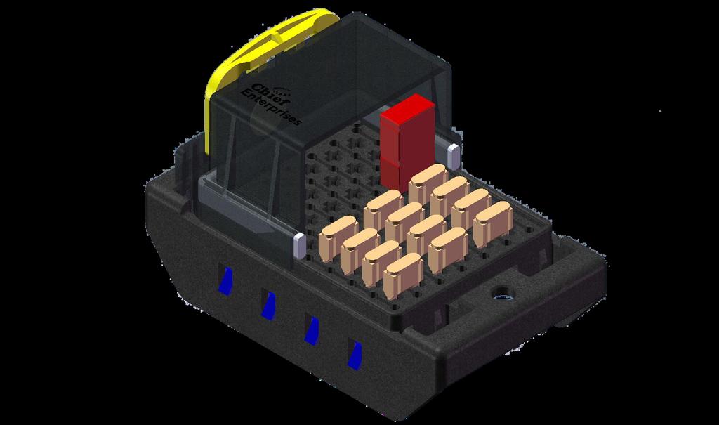
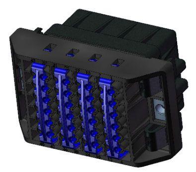
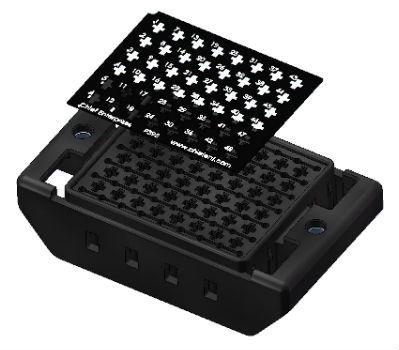
3 Rev: 10-Apr-2018 Page 3/26 Description of Product Chief Enterprises BRIC Power Distribution Module (PDM) houses plug-in electrical components such as Fuses (Mini, ATO, Maxi), Relays (280, ISO, Maxi), Circuit Breakers, Diodes, and similar components, in a sealed chamber. The PDM is designed for use in construction, agriculture, and heavy duty transportation applications where ruggedness is required. Chief BRIC PDMs are available as fixed 280-style plug in, or in configurable assemblies called BRIC Fusion, which houses higher amperage components. BRIC Fusion uses sonic welding to combine separate inserts into a environmentally sealed base. By using separate inserts, 19 unique combinations are available. A minimal PDM consists of a Base and Cover. Wire leads with terminals and single wire seals (SWS) are inserted in the bottom of the base, and unused cavities are plugged. Electrical components are mated to the terminals from the top of the base, and a cover with integrated compression gasket is assembled from the top. The cover is secured to the base with snap-fits. Covers are available with and without a hydrophobic vent. The vent allows a small air flow in/out of the sealed chamber to relieve pressure differentials from component heating. In applications with low heat generation and minimal water exposure, the vent may not be required. For more demanding applications, the vent will prevent gasket blow-by and water intrusion into the sealed chamber. The PDM can be pre-wired before mounting, or wired after mounting. The PDM should be rigidly secured using two M6 screws, fastening to integrated steel M6 nuts in the base. Accessories such as TPAs, CPAs, Labels, and Tethers are available, and can be specified as needed. Our Engineering team can assist in selecting the components. While the design of the PDM has been highly engineered and tested, each application can have unique characteristics that affect its functionality. Recommendations in this document are based on typical configurations and applications, but cannot cover the extent of all uses. We recommend that OEMs test the PDM in their configuration, with the specified electrical components and environmental requirements.

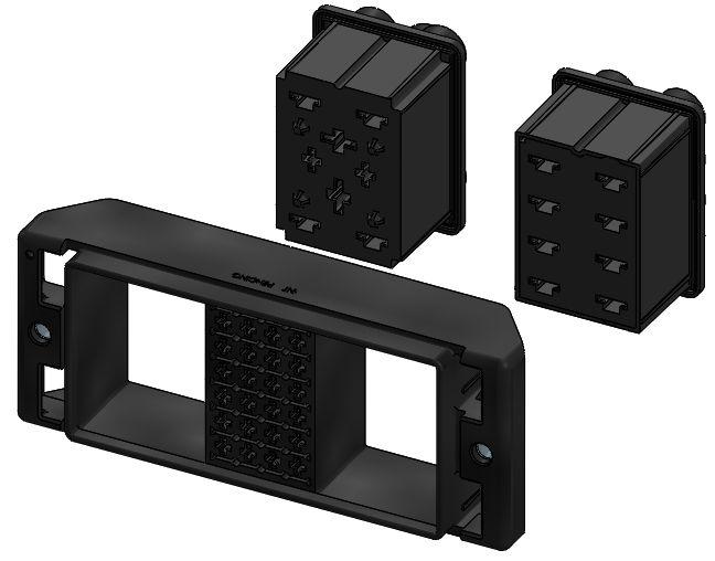

4 Rev: 10-Apr-2018 Page 4/26 Configurations 24 Way 48 Way 84 Way Fusion Cover with Vent without Vent with CPA without CPA
5 Rev: 10-Apr-2018 Page 5/26 BRIC Fusion Configurations
6 Rev: 10-Apr-2018 Page 6/26 Basic Dimensions (reference only - see drawings for dimensions and tolerances) PDM Size A 24 Way Way Way Fusion 139.3

7 Rev: 10-Apr-2018 Page 7/26 Mounting


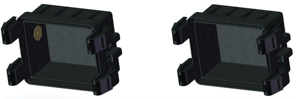
8 Rev: 10-Apr-2018 Page 8/26 *arrow indicates upward direction Base Poka-Yoke The base may be assembled in two orientations. If necessary, use a location pin or sensor to orient the PDM with the 2.0 mm hole.

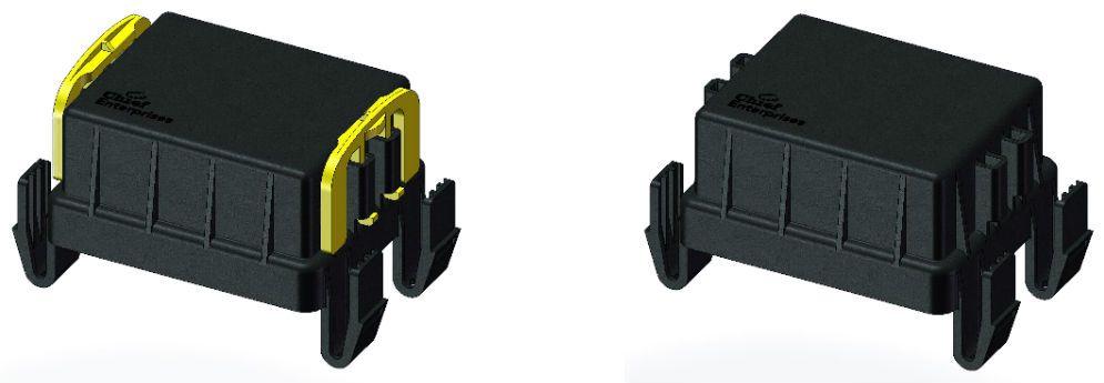
9 Rev: 10-Apr-2018 Page 9/26 Assembly Instructions Installing the cover into the base: There are multiple ways to engage the cover into the base, but there are two methods that are recommended by Chief. Method 1 The first method involves pushing on the Yellow CPA on the ends of the cover. With the CPA in its unlocked position, push on the middle of the CPA until the two corner locking clips are locked into place. A distinct clicking sound will be made when the cover locking clips are properly engaged. Repeat this process on the other end of the cover to fully engage it to the base. See the picture below demonstrating this method.
.")

10 Rev: 10-Apr-2018 Page 10/26 Method 2 The second method involves pushing on the cover while the Yellow CPA is already in its locked position. Make sure the CPA s are in their locked position (see CPA locking method section). Starting at one end of the cover, push down on each corner until the locking clips are fully engaged into its place on the base, making a distinct clicking sound. Repeat this process on the other end of the cover to fully engage the cover. See the picture below demonstrating this method properly.

11 Rev: 10-Apr-2018 Page 11/26 Installing the 280 TPA The 280 TPA shall be installed after all wires or plugs are assembled into the base. Each TPA has slots that line up over each wire cavity that house the wire itself. Before attempting to engage the TPA into the base, line up the wires with their designated slots on the TPA. Once the wires are lined up in their respective slots on the TPA, push the ends in so they are able to to slide down into the base. Push down on the TPA until the ledge on each end snaps into its place on the base and locks in. A screwdriver or other tool may be needed to ensure the TPA is fully engaged. See pictures below demonstrating these steps. To ensure proper installation, confirm the ledge on the TPA is flush with the surface in its locking position on the base on each side. See pictures below for examples of what it should look like when the TPA is properly installed.


12 Rev: 10-Apr-2018 Page 12/26 Lining up the wires in the wire slots on the TPA: Ends pushed in and sliding into base:


13 Rev: 10-Apr-2018 Page 13/26 Screwdriver being used to aid in installation: Improper Installation Proper Installation

14 Rev: 10-Apr-2018 Page 14/26 CPA Locking Method By pushing down on the middle of the CPA, it will snap into its position and make a distinct clicking noise when it is properly locked. When the CPA s are locked they will prevent the locking clips from disengaging when they are pressed in. See below for pictures showing the locked and unlocked positions.
 and a small hammer.")

15 Rev: 10-Apr-2018 Page 15/26 Disassembly Instructions 280 TPA Disassembly Once the TPA is locked into position, it can only be removed with a tool. Use a small screwdriver (or similar tool) and a small hammer. With the screwdriver, push on the ledge of one side of the TPA on an angle as shown in the pictures below. Using the small hammer, tap on the end of the screwdriver until the ledge of the TPA is knocked from its locking position, disengaging that end of the TPA from the base. Repeat this process on the other end to fully disassemble the TPA from the base. A removed TPA should not be reused.

16 Rev: 10-Apr-2018 Page 16/26 Cover Disassembly Method To remove the cover when it is fully locked into the base, first make sure the CPA s are in their unlocked position. The cover can be taken off by pressing each locking tab until a clicking noise is made, disengaging that locking clip from the base. The easiest way to remove the cover is to press two of the locking clips on opposite ends and then move on to the other two locking clips. See below for a picture demonstrating the easiest method to remove the cover.
17 Rev: 10-Apr-2018 Page 17/26 Terminal Systems Example part numbers are shown in the table below, this table is for reference only -- the latest information is available from the terminal manufacturers. Note that x- and -x represent material, plating, or tooling options. MCP 2.8 Cavity Plug: Terminal Extraction Tool: Wire Size mm² (AWG) Insulation Diameter (mm) Strip Form Loose Piece Applicator Tool Hand Crimp Tool (Die Set) Single Wire Seal (22-20) x x x x x (20-18) x x x x x (16-14) x x x x x (12) x x
18 Rev: 10-Apr-2018 Page 18/26 MCP 6.3 Cavity Plug: Terminal Extraction Tool: Wire Size mm² (AWG) Insulation Diameter (mm) Strip Form Loose Piece Applicator Tool Hand Crimp Tool (Die Set) Single Wire Seal (20-18) x x x x x > (16-14) x x x x x > (12) x x x x x > (10) x x x x x
19 Rev: 10-Apr-2018 Page 19/26 MCP 9.5 Cavity Plug: N/A Terminal Extraction Tool: Wire Size mm² (AWG) Insulation Diameter (mm) Strip Form Loose Piece Applicator Tool Hand Crimp Tool (Die Set) Single Wire Seal (8) x x x x x (8) x x x x x (6) x x x x
20 Rev: 10-Apr-2018 Page 20/26 Delphi Metri Pack 800 Cavity Plug: P693 Terminal Extraction Tool: Wire Size mm² (AWG) Insulation Diameter (mm) Strip Form Loose Piece Applicator Tool Hand Crimp Tool Single Wire Seal 5.0 (10) L Inquire for details or (8) L Inquire for details
21 Rev: 10-Apr-2018 Page 21/26 Electrical & Environmental Ambient Temperature: -40 to 120 ºC Max Current per Terminal: 30 Amps Intermittent 20 Amps Continuous (with temperature derating) Max Continuous Current per PDM: With Vent: 360 A Without Vent: 300 A (for IP rating) Max Intermittent Current per PDM: Must be determined by customer Water & Dust Ingress Protection: IP 67 Wire Range: Environmental Compatibility: Compliance: 24 to 12 AWG Resistant to most underhood chemicals, UV Stable ROHS Cover: UL 94HB Body: UL 94V-0 Seal: UL 94HB Materials: Cover: PPE + PA Body: Glass Reinforced PBT Seal: Silicone Design Recommendations: Place heat-generating components on perimeter Maximize wire gauge for heat dissipation Mount in area with airflow, away from heat sources
22 Rev: 10-Apr-2018 Page 22/26 Temperature Derating using MCP 2.8 Terminals The PDM materials can withstand high temperatures before degradation, but Chief does not recommend exceeding 120 ºC for any components or the PDM itself. Thorough testing has demonstrated the relationship between temperature and current on a PDM with properly specified wire gauges. At no point should the base or interior components be exposed to temperatures exceeding 120 ºC, or the maximum component temperature, whichever is lower. For example, a 48-way PDM with 15A per circuit continuous (24 circuits of 15A each) should be in ambient temperature below ~77 ºC. The chart below shows this as a derating for MCP 2.8 terminals. Note that temperature derating has not been performed on other terminals used in BRIC Fusion.
23 Rev: 10-Apr-2018 Page 23/26 Validation Testing Combined Temperature Vibration HALT: High temperature Soak: Low Temperature Soak: Temperature Cycle: Temperature Shock: Drop Test: Vibration: Particle Impact: -40 to 125 ºC plus vibration 125 ºC (Operational) -40 ºC (Operational) -40 to 125 ºC, 10 Cycles (Operational) -40 to 90 ºC, 100 Cycles (Operational) 1 Meter onto Hardwood, All Sides Random 100 hrs (Operational) Simulated Gravel Water & Dust Ingress: IP 67 Combined Temperature & Humidity: Salt Spray: Chemical Resistance: Ozone: Accelerated Weathering (Ultraviolet): 100 Hours (Operational) 96 Hours Oils, Fertilizer, Urea, NPK 70 hours 2,000 Hours complete & passed in process/planned


24 Rev: 10-Apr-2018 Page 24/26 Accessories & Options TPA Custom Labels Tether Side Mount
25 Rev: 10-Apr-2018 Page 25/26 Required for most BRIC Foam - Provides anti-backout pressure on tall components. Required for all applications with relays, circuit breakers, diodes, or other 25mm tall components. Not required for applications with only ATM or ATO fuses. Not recommended with manual reset circuit breakers. Required for BRIC Fusion with Maxi Fuses Metripack 800 TPA - Terminals are single tang. Optional for 280 BRIC 280 TPA - MCP terminals are dual tang and have sufficient pullout retention. Optional for all BRIC CPA - Prevents accidental unlocking of cover. Without CPA's, IP rating of BRIC may be less than IPx7 due to water pressure disengaging snap fits Breather - Equalizes pressure, minimizing risk of water intrusion. Not directly applicable to IP ratings. Seal - Creates barrier between cover and base. Without seal, IP rating is approx IP33. Tether Diode Key Universal Brackets Labels Laser Marking

26 Rev: 10-Apr-2018 Page 26/26 Custom Laser Marking Chief provides custom laser marking on the covers of all sizes of the BRIC. Logos, instructions, schematics, lot codes, and other markings can be per your specification. Our laser marking is a permanent, high resolution monochromatic/grayscale, but can be prone to abrasion and is not meant to be UV resistant. Text size is legible to 1.0 mm height. Submit artwork in any standard electronic format.
Vehicle Electrical Center (VEC) Series
 Series") Vehicle Electrical Center (VEC) Series Eaton Vehicle Electrical Centers (VECs) are power distribution centers capable of high power density and water & dust ingress protection with the flexibility to customize
Vehicle Electrical Center (VEC) Series Eaton Vehicle Electrical Centers (VECs) are power distribution centers capable of high power density and water & dust ingress protection with the flexibility to customize
Application Specification. 2P Mini Fuse Box. 2P Mini Fuse Box - GENERAL PARTS, NOT RESTRICTED - A New Release 30OCT2015 Kunal G Rajesh Koti
 Application Specification 114-72110 30-OCT.-2015 Rev A 2P Mini Fuse Box 2P Mini Fuse Box - GENERAL PARTS, NOT RESTRICTED - A New Release 30OCT2015 Kunal G Rajesh Koti LTR Revision Record Date DWN APVD
M-9424-M50CJ INTAKE MANIFOLD INSTALLATION INSTRUCTIONS
 Please visit www.fordracingparts.com for the most current instruction information!!! PLEASE READ ALL OF THE FOLLOWING INSTRUCTIONS CAREFULLY PRIOR TO INSTALLATION. AT ANY TIME YOU DO NOT UNDERSTAND THE
PRODUCT SPECIFICATION
 1 of 14 Table of Contents 1.0 Scope... 3 2.0 Product Description... 3 2.1. Direct Connect (wire to board application)... 3 2.2. Inline Applications (wire to wire application)... 3 2.3. Receptacle Assembly...
Sealed Sensor Connector (SSC) System
 System") Introduction Product Features Robust housing, glass filled PBT for high temperature applications Terminal Position Assurance (TPA) to assure proper position of contact in housing Damage protected internal
Introduction Product Features Robust housing, glass filled PBT for high temperature applications Terminal Position Assurance (TPA) to assure proper position of contact in housing Damage protected internal
PMC2003 Harness Assemblies
 PMC2003 Harness Assemblies Instruction Sheet 27 JAN 11 TPA/Spacer Base Part Numbers 50-Way PCM2003 Connector Assemblies 1438129 Harness Assembly 1393364 1393365 Tyco Electronics.064 Terminal Assembly 1642303
JUL 14 Rev B
 Power Triple Lock (PTL) Connector System Application Specification 4-068 2 JUL 4 Rev B NOTE All numerical values are in metric units [with U.S. customary units in brackets]. Dimensions are in millimeters.
Modification Record of Product Specification
 Modification Record of Product Specification No, DSP-14 1303 Product Name SRV Connector Systems Rev. No, Note Reason Place Date Engineer R0 Initial Release DEC 2.19.14 A.M. Page 1/17 PRODUCT SPECIFICATION
POWER DISTRIBUTION MODULE - 8 POSITION - SEALED
 POWER DISTRIUTION MODULE - 8 POSITION - SELED This module can be fitted with a mixture of 80 style components such as Mini fuses, mini circuit breakers, mini diodes, mini resistors and ISO 80 relays. It
JUNCTION BLOCK DESCRIPTION OPERATION XK 8W-97 POWER DISTRIBUTION 8W
 XK 8W-97 POWER DISTRIBUTION 8W - 97-7 JUNCTION BLOCK DESCRIPTION An electrical Junction Block(JB) is concealed beneath the driver side of the instrument panel in the passenger compartment of the vehicle.
POWER TRIPLE LOCK* Connector System
 POWER TRIPLE LOCK* Connector System Application Specification 114-106118 23 MAY 18 Rev J NOTE All numerical values are in metric units [with U.S. customary units in brackets]. Dimensions are in millimeters.
nterconnect compatibility new SEALED CONNECTORS harsh environment dual seals for harsh environments ergonomic locking tab for easier mating
 new harsh environment SEALED CONNECTORS nterconnect dual seals for harsh environments ergonomic locking tab for easier mating compatibility AT Series plug wedges ensure a proper seal placement and contact
w w w. h d o n l i n e s h o p. d e HEATED HAND GRIP KITS GENERAL REMOVAL -J02983 REV Kit Number Models Kit numbers Service Parts
 -J098 REV. 007-0-0 GENERAL Kit Number 56047-0B, 5607-0B, 5674-0B, 5696-0B, 565-0B, 5669-0A, 56694-04A, 56750-04A, 5688-0A, 569-05, 5696-05, 56997-07 Models For model fitment information, please see the
HS6B Series Subminiature Interlock Switch
 HS6B Series Subminiature Interlock Switch HS6B features: Only 78 x 30 x 15mm Allows highest level of safety by having 3 contacts: dual load contacts + monitoring contact (ISO13849-1, EN954-1) Two actuator
PRODUCT SPECIFICATION
 ML-XT COMMERCIAL VEHICLE CONNECTOR SERIES 1.0 SCOPE This Product Specification relates to the ML-XT Commercial Vehicle, (CV), Power and/or Signal wire-to-wire connector system. This system consists of
Part Name/Description Part No. PF3000 PF 3000 Pro U-Bracket Short Bracket PF3000 Pro
 Note: Indented items indicate parts included in an assembly listed above Part Name/Description Part No. PF3000 PF 3000 Pro U-Bracket Short 2000105-2 1 PFadvantage Bracket PF3000 Pro 2000773 1 Cable Kit
Water-Proof Connectors
 Water-Proof Connectors Edac s waterproof Wire-to-Wire and Wire-to-Board series was designed for both extreme moisture and nonsubmersion applications supporting both low-level signal and power applications
ROAD TECH ZUMO GLOBAL POSITIONING SYSTEM (GPS) HANDLE- BAR MOUNT KIT
 HANDLE- BAR MOUNT KIT") -J046 REV. 008-08- ROAD TECH ZUMO GLOBAL POSITIONING SYSTEM (GPS) HANDLE- BAR MOUNT KIT GENERAL Kit Number 965-08 Models This kit is required when using a Road Tech Zumo GPS unit on specific model motorcycles.
-J046 REV. 008-08- ROAD TECH ZUMO GLOBAL POSITIONING SYSTEM (GPS) HANDLE- BAR MOUNT KIT GENERAL Kit Number 965-08 Models This kit is required when using a Road Tech Zumo GPS unit on specific model motorcycles.
Wedge in Plugs Stock No
 Amphenol Connectors Description Plugs Stock No. Receptacles Stock No. 2-way 38170 38171 3-way 38172 38173 4-way 38174 38175 6-way 38176 38177 8-way 38178 38179 12-way 38180 38181 Wedge in Plugs Stock No.
Technical Data, High Power 2-way* Cannon APD / ISO Connectors. Electrical Data. Mechanical Data. Environmental Data (acc.
 Technical Data, High Power 2-way* Electrical Data Operating Voltage Operating Current Contact Resistance Voltage Proof Insulation Resistance Mechanical Data 48 VDC* see derating curve 2 mω max. 1000 VAC,
CIRCUIT PROTECTION SOLUTIONS FOR AUTOMOTIVE APPLICATIONS. Automotive Commercial Vehicle Products (CVP)
") CIRCUIT PROTECTION SOLUTIONS FOR AUTOMOTIVE APPLICATIONS Automotive Commercial Vehicle Products (CVP) Power Distribution Centers Flexible Electrical Center 92 FLEC Flexible Electrical Center 92 Hard-Wired
CIRCUIT PROTECTION SOLUTIONS FOR AUTOMOTIVE APPLICATIONS Automotive Commercial Vehicle Products (CVP) Power Distribution Centers Flexible Electrical Center 92 FLEC Flexible Electrical Center 92 Hard-Wired
SECTION SECTION SECTION EATON 2016 Arrow Hart Buyers Guide
 F SECTION SECTION SECTION 1 EATON 2016 Arrow Hart Buyers Guide www.arrowhart.com /arrowhart FSECTION Cam-Lok Single Pole Connectivity Table of contents Product selector guide F-3 NEMA rating system F-4
2. Use Extraction Tool (contact extraction tool). Insert releasing tip into the REAR of the. cavity between the spring and center wall of the
. Insert releasing tip into the REAR of the. cavity between the spring and center wall of the") Twin Leaf PC Board Edge Connectors are designed for wire to pc board applications. To meet specific circuit requirements, housings are supplied (1) to be assembled using contacts, retaining springs, and
Twin Leaf PC Board Edge Connectors are designed for wire to pc board applications. To meet specific circuit requirements, housings are supplied (1) to be assembled using contacts, retaining springs, and
General Applicability Note: Recommended Tools. Personal & Vehicle Protection Safety Goggles Seat Covers Floor Covers Special Tools. Installation Tools
 TOYOTA HIGHLANDER/HIGHLANDER HV 2008- Preparation Part #: PT923-00111 Conflicts: JBL Audio, Factory Navigation NOTE: Part number of this accessory may not be the same as the part number shown. Kit Contents:
circuit protection & wiring accessories
 circuit protection & wiring accessories CIRCUIT BREAKERS P1 P BLOCKS & BUSBARS TERMINAL BLOCKS P2 P3 CONNECTORS, TERMINALS & FUSES P4 CLAMPS, CLEATS, CLIPS & TIES P5 P1 circuit protection & wiring accessories
ELECTRICAL CONNECTORS B.1
 ELECTRICAL CONNECTORS B. GENERAL The following table provides a brief description of the connectors found on your motorcycle. Connector numbers are listed in [brackets] in this manual. Table B-. Electrical
Electrical. Hardware & Fastening Solutions. Battery Supplies. J-Case Fuses - Regular... Page 162
 Flag Style... Page 156 Electrical Batteries... Page 153 Mounting Pads (Adhesive Backed)... Page 161 Battery Supplies J-Case Fuses - Regular... Page 162 Booster Cable Supplies... Page 153 J-Case Fuses -
Part Number: TTU-BGB14-DRL TTU-BGP14-DRL
 11/15/16 TOYOTA TUNDRA 2014-17 Billet Grille w/led DRL Part Number: TTU-BGB14-DRL TTU-BGP14-DRL Kit Contents Item # Quantity Reqd. Description 1 2 LED DRL 2 1 Driver Box 3 1 Switch 4 1 User Card 5 2 Hardware
Luminus Series Amphenol Pcd
 Luminus Series Amphenol Pcd Amphenol Pcd Pcd is is one one of of the the world s leading suppliers of of interconnect products for for Military, Commercial Aerospace and and Industrial applications. Located
Delphi Harsh Environment Series (HES) Connection Systems
 Connection Systems") The Delphi Harsh Environment Series (HES) include circular connectors, terminals, and a J1939 diagnostic circular connector. The 24 shell size industry standard connector includes six terminal configurations
The Delphi Harsh Environment Series (HES) include circular connectors, terminals, and a J1939 diagnostic circular connector. The 24 shell size industry standard connector includes six terminal configurations
MX150L ASSEMBLY INSTRUCTIONS
 CONNECTOR PLUG ASSEMLY TERMINAL INSERTION MX150L ASSEMLY INSTRUCTIONS 1. egin assembly of the crimped male terminals into the plug housing by making sure the Terminal Position Assurance feature () is in
SECTION SECTION. EATON 2014 Arrow Hart Buyers Guide
 F SECTION SECTION 1 EATON 2014 Arrow Hart Buyers Guide FSECTION Cam-lok Single Pole Connectivity Table of contents Product selector guide F-3 NEMA rating system F-4 F-series F-5 E1010 F-6 E1012 F-7 F-series
Economy Power (EP) 2.5 Contacts; Plug and Receptacle Housings; and Vertical and Right-Angle Headers
 2.5 Contacts; Plug and Receptacle Housings; and Vertical and Right-Angle Headers") Economy Power (EP) 2.5 Contacts; Plug and s; and Vertical and Right-Angle Headers Application Specification 114-13315 09 JUN 17 Rev G NOTE All numerical values are in metric units [with U.S. customary
Economy Power (EP) 2.5 Contacts; Plug and s; and Vertical and Right-Angle Headers Application Specification 114-13315 09 JUN 17 Rev G NOTE All numerical values are in metric units [with U.S. customary
The steering column is of a modular construction and features easy to service electrical switches.
 file://c:\tso\tsocache\vdtom_5368\svk~us~en~file=svkb4a01.htm~gen~ref.htm Page 1 of 3 Section 11-04A: Steering Column, Ranger DESCRIPTION AND OPERATION 1997 Ranger Workshop Manual Steering Column NOTE:
Industrial plug-in connectors HEAVYCON EVO. efficient at a twist of the wrist
 Industrial plug-in connectors HEAVYCON EVO efficient at a twist of the wrist For more efficiency in your system HEAVYCON EVO Heavy-duty plug-in connectors are established on the market and are used in
MICRO-CON-X 2-7 NEW PRODUCT BULLETIN C708
 FEATURES & BENEFITS Up to 7 contacts in compact design IP-67 rating, at the face (when mated) IP-67 molded cable assemblies (when mated) All plastic design is light weight Variety of standard options to
ACD-PRO Install in 2008 EvoX
 Turning in a counter clockwise direction, unscrew ift knob ACD-PRO Install in 2008 EvoX Slide back and remove the floor console panel assembly Pull up to remove the center console tray Disconnect the plug
w w w. h d o n l i n e s h o p. d e ROAD TECH QUEST GLOBAL POSITIONING SYSTEM (GPS) MOUNTING KIT GENERAL INSTALLATION -J03554 REV.
 MOUNTING KIT GENERAL INSTALLATION -J03554 REV.") -J03554 REV. 007-08-0 ROAD TECH QUEST GLOBAL POSITIONING SYSTEM (GPS) MOUNTING KIT GENERAL Kit Number 900-05 Models For model fitment information, please see the P&A Retail Catalog or the Parts and Accessories
-J03554 REV. 007-08-0 ROAD TECH QUEST GLOBAL POSITIONING SYSTEM (GPS) MOUNTING KIT GENERAL Kit Number 900-05 Models For model fitment information, please see the P&A Retail Catalog or the Parts and Accessories
#TL T EA888 GEN 3 FUELING SYSTEM/ INSTALLATION INSTRUCTIONS
 #TL100069 2.0T EA888 GEN 3 FUELING SYSTEM/ INSTALLATION INSTRUCTIONS Notes: These instructions were written for a North American specification MkVII GTI. Other models, like the Golf R, are similar. When
R49 SERIES TABLE OF CONTENTS
 PRODUCT GUIDE R49 SERIES TABLE OF CONTENTS 3 Product Overview 4 Features Spotlight 5 Code Logic 6 Panel Mount Receptacle Female 7 Panel Mount Receptacle Male 8 Cable Mount Receptacle 9 Bulkhead Mount Receptacle
SG-B1 SERIES / SG-A1 SERIES
 643 Door with Solenoid Interlock / Door Ultra-slim SG-B1 SERIES / SG-A1 SERIES Related Information General terms and conditions... F-7 General precautions... P.1501 PHOTO PHOTO Conforming to Machine &
Disassembly. 1 Pull off the QUIK-LOK cable from the machine.
 Special Tools Require Important! Torx TX0 bit 0 0 Screwdriver Torx 0 0 0 Forcing Discs 0 Before beginning the maintenance work, perform an initial check with a high voltage test according to VDE (see chapter
JEEVES. JEEVES Installation Manual. Installation Manual The Easiest Do-It-Yourself Dumbwaiter on the Market
 1 888-323-8755 www.nwlifts.com JEEVES Installation Manual The Easiest Do-It-Yourself Dumbwaiter on the Market This manual will cover the installation procedure step-by-step. The installation of this dumbwaiter
AMPSEAL 16* Connector System 24 JUN 13 Rev C
 Application Specification 114-13065 AMPSEAL 16* Connector System 24 JUN 13 i All numerical values are in metric units [with U.S. customary units in brackets]. Dimensions are in millimeters [and inches].
AIR INTAKE EMERGENCY SHUT-OFF VALVE C50207 AIR INTAKE SHUT-OFF VALVES APPLICATION FORD 6.7L POWERSTROKE.
 AIR INTAKE EMERGENCY SHUT-OFF VALVE C50207 AIR INTAKE SHUT-OFF VALVES APPLICATION 2011-2016 FORD 6.7L POWERSTROKE www.powerhalt.com Thank you for your purchase of a PowerHalt Air Intake Emergency Shut-Off
TX³ RCCBs 2P up to 100 A
 87045 LIMOGES Cedex Telephone number: +33 (0)5 55 06 87 87 Fax: +33 (0)5 55 06 88 88 TX³ RCCBs CONTENTS PAGE 1. Description, use... 1 2. Range... 1 3. Overall dimensions... 1 4. Preparation - Connection...
nual k Voltage Stabilizer N) manual New Brunswick Voltage Stabilizer Operating manual
 manual New Brunswick Voltage Stabilizer Operating manual") nual k Voltage Stabilizer N) manual New Brunswick Voltage Stabilizer Operating manual Copyright Copyright 2014 Eppendorf AG, Germany. No part of this publication may be reproduced without the prior permission
nual k Voltage Stabilizer N) manual New Brunswick Voltage Stabilizer Operating manual Copyright Copyright 2014 Eppendorf AG, Germany. No part of this publication may be reproduced without the prior permission
1, 2, 4, 6, 8, 10 and 12 in. (50, 100, 150, 200, 254, 300 mm) for all models Clevis Ends
 for all models Clevis Ends") M-Track DC Motor Acme Screw Up to 65 lb. (74 N) Rated Load Up to.75 in. (45 mm)/sec. Travel Speed M-Track compact units are completely self-contained and sealed to allow use in small spaces without sacrificing
M-Track DC Motor Acme Screw Up to 65 lb. (74 N) Rated Load Up to.75 in. (45 mm)/sec. Travel Speed M-Track compact units are completely self-contained and sealed to allow use in small spaces without sacrificing
JOHN DEERE GATOR SWITCH PANEL INSTRUCTIONS FITS 1GTRXUV2 AND 1GTRXUV4 CABS (p/n: 1XUVSP)
") P. 1 of 5 JOHN DEERE GATOR SWITCH PANEL INSTRUCTIONS FITS 1GTRXUV2 AND 1GTRXUV4 CABS (p/n: 1XUVSP) Note: Harness Extension Kit Required for 4 Passenger (p/n: 1XUV4WHEK) This manual is the property of the
P. 1 of 5 JOHN DEERE GATOR SWITCH PANEL INSTRUCTIONS FITS 1GTRXUV2 AND 1GTRXUV4 CABS (p/n: 1XUVSP) Note: Harness Extension Kit Required for 4 Passenger (p/n: 1XUV4WHEK) This manual is the property of the
Detroit Speed, Inc. Electric Headlight Door Kit Corvette P/N: &
 Detroit Speed, Inc. Electric Headlight Door Kit 1968-82 Corvette P/N: 122006 & 122007 The Detroit Speed Inc. Electric Headlight Door Kit replaces the stock vacuum actuated system on all 1968-82 Corvettes.
Application Specification Pin&3Pin Miniature waterproof connector 28July2016 REV: C
 Application Specification 114-137093 2Pin&3Pin Miniature waterproof connector 28July2016 REV: C 1. INTRODUCTION This specification covers the requirements for application of 2Pin&3Pin Miniature waterproof
INSTALLATION & OWNER S MANUAL
 p. 1 of 13 INSTALLATION & OWNER S MANUAL Polaris Ranger 400-EV PathPro SS Cab (fits 2010 - current) (p/n: 1PRG400FS) The contents of this envelope are the property of the owner. Be sure to leave with the
DRIVE SHAFT LOCATION INDEX
 DRIVE SHAFT LOCATION INDEX 2005 DRIVELINE/AXLE Drive Shaft - MX-5 Miata Fig. 1: Identifying Drive Shaft Location DRIVE SHAFT PRE-INSPECTION 1. Inspect the dust boot on the drive shaft for cracks, damage,
w w w. h d o n l i n e s h o p. d e LAYBACK LICENSE PLATE AND TURN SIGNAL RELOCATION KIT INSTALLATION GENERAL -J03892 REV Kit Number
 -J0 REV. 00-0-0 LAYBACK LICENSE PLATE AND TURN SIGNAL RELOCATION KIT GENERAL Kit Number 0-0 Models For model fitment information, please see the P&A Retail Catalog or the Parts and Accessories section
S826, S926 Series Dual changeover switches with positive opening operation and wiping contacts Catalogue D26.en
 2 Snap-action switches S826, S26 Series Dual changeover switches with positive opening operation and wiping contacts Catalogue D26.en 2 Snap-action switches S826 Series Dual changeover switches with positive
w w w. h d o n l i n e s h o p. d e CHROME FAN KIT GENERAL INSTALLATION -J04347 REV Kit Number Models Kit Contents
 -J0447 REV. 008-08-05 CHROME FAN KIT GENERAL Kit Number 996-08 Models For model fitment information, see the P&A Retail Catalog or the Parts and Accessories section of www.harley-davidson.com (English
MODEL FP-10. Read Instructions Carefully! CURTIS INSTRUMENTS, INC Kisco Ave. Mount Kisco, New York
 MODEL FP-10 CURTIS INSTRUMENTS, INC. 200 Kisco Ave. Mount Kisco, New York 10549 914-666-2971 www.curtisinstruments.com 53090 Rev A 11/16 Read Instructions Carefully! SAFETY INSTRUCTIONS This product was
FOG LAMPS INSTALL KIT
 FOG LAMPS INSTALL KIT PT CRUISER INSTALLATION INSTRUCTIONS Read entire instructions thoroughly before starting. For proper aiming of fog lamps, follow procedures in the service manual. NOTES: Left and
Circuit Breaker Types
 Circuit Breaker Types Automatic Reset The circuit breaker cycles continuously during an overload condition until the overload is removed or corrected. Modified Reset The circuit breaker contains an additional
Operating Instructions
 Operating Instructions Load and Motor Switch, Load-Break Switch > 8544/1 Contents 1 Contents 1 Contents...2 2 General Information...2 3 General Safety Instructions...3 4 Designated Use...4 5 Technical
MAKING MODERN LIVING POSSIBLE. Quick Setup VLT FCM 300 Series. Phone: Fax: Web: -
 MAKING MODERN LIVING POSSIBLE Quick Setup VLT FCM 300 Series Factory setting Motors type B14 & B34 mounting Reset (pushbutton) Start Jog Speed reference Fig. 1 - Reset to be closed short time for resetting
w w w. h d o n l i n e s h o p. d e TWO-INCH TACHOMETER KIT GENERAL INSTALLATION -J03991 REV Kit Number Models Kit Contents
 -J0399 REV. 006-05- GENERAL Kit Number 67564-05A Models This kit fits: 004 and later FXD, FXDC, FXDX, and FXDWG 004 and later Softail (exept FLSTN) 004 and later FLHR/C 004 and later XL 006 and later FXDB
INSTALLATION MANUAL. Ford 3.5L F
 INSTALLATION MANUAL Applications Rapid Flow Part Number Ford 3.5L F150 11 51202 Parts Included and Tools Needed: Parts Included This section displays the parts included in the package and the tools needed
2011 Model Year BBCV Vision and Model Year D3 All American CORRECTIVE ACTION ---- PROCEDURE
 Cruise Control May Not Deactivate 2011 Model Year BBCV Vision and 2010-2011 Model Year D3 All American ISSUE Once activated the cruise control feature may not deactivate as designed when the service brakes
Contents. 1. Preface Product Outline Model Number Construction Specifications Outline Drawings and Wiring diagram...
 TY-KM31-001A 1/13 Contents 1. Preface.. 2 2. Product Outline.. 2 3. Model Number Construction.. 2 4. Specifications.. 3 5. Outline Drawings and Wiring diagram... 4 6. External Connection.. 10 7. Function
Cinch Connectors. Providing a broad range of interconnect solutions the world over.
 Transportation by Cinch Connectors. Providing a broad range of interconnect solutions the world over. In operation since 1917, Cinch Connectors, a Bel Fuse Company, is a multi-national manufacturer of
Fisher 2052 Diaphragm Rotary Actuator
 Instruction Manual 2052 Actuator Fisher 2052 Diaphragm Rotary Actuator Contents Introduction... 1 Scope of Manual... 1 Description... 1 Specifications... 4 Installation... 4 Actuator Mounting and Changing
INSTALLATION INSTRUCTIONS
 1. Note: It is recommended this install be done with a minimal amount of fuel in the tank. This will reduce fuel spills and make installation easier and safer. Draining the tank is recommended. INSTALLATION
DX³ RCCBs - ID 4P up to 100 A
 87045 LIMOGES Cedex Telephone number: +33 (0)5 55 06 87 87 Fax: +33 (0)5 55 06 88 88 DX³ s - ID CONTENTS PAGE 1. Description, use... 1 2. Range... 1 3. Overall dimensions... 1 4. Preparation - Connection...
OPERATOR, PARTS AND INSTALLATION MANUAL. BX7330 AVENTA TM Tow Bar TOWING PRODUCTS DIVISION
 A V E N T A TM OPERATOR, PARTS AND INSTALLATION MANUAL BX7330 AVENTA TM Tow Bar TOWING PRODUCTS DIVISION SAFETY DO NOT INSTALL, OPERATE OR USE THIS EQUIPMENT UNTIL THE FOLLOWING OPERATING AND SAFETY INSTRUCTIONS
R49 & R24 PRODUCT GUIDE
 PRODUCT GUIDE Amphenol EEC, Inc. 4050 N Rockwell St Chicago IL 60618 USA P 773.463.8343 F 773.463.8344 W eecchicago.com 2 4 5 6 7 8 9 10 11 12 13 14 15 16 17 18 19 20 21 Product Overview Features Spotlight
Signal Mirror Installation Instructions
 Signal Mirror Installation Instructions Ford F-250 to F-750 Pick-Up, Super-Duty 1998-2007 Trailer Tow Mirror Ford Excursion XLT/Limited 2000-2002 Trailer Tow Mirror Ford Excursion (all models) 2003-2005
INSTALLATION INSTRUCTIONS 88518
 INSTALLATION INSTRUCTIONS 88518 For Rancho Suspension Systems RS6518: 2009 FORD F-150 4WD READ ALL INSTRUCTIONS THOROUGHLY FROM START TO FINISH BEFORE BEGINNING INSTALLATION Rev A IMPORTANT NOTES! WARNING:
Aug07 Rev A All Paragraphs Revised
 Qualification Test Report Universal MATE-N-LOK* Connector 110-213 28Aug07 Rev A All Paragraphs Revised 1. INTRODUCTION 1.1. Purpose 1.2. Scope Testing was performed on Universal MATE-N-LOK* connectors
ALL AMERICAN BILLET. Front Drive System - Small Block Ford Installation Instructions
 ALL AMERICAN BILLET Front Drive System - Small Block Ford Installation Instructions Small Block Ford with AC & PS All American Billet Store (800) 764-0926 www.allamericanbilletstore.com Items needed for
HS5E Miniature Interlock Switches with Solenoid
 Small interlock switch with four poles and solenoid. Ideal for applications in small spaces. Compact body. 3 40 46 mm. Four-pole internal switches. Gold-plated contacts. Spring lock and solenoid lock types
ML-XT SEALED CONNECTION SYSTEM BETTER DESIGN BETTER PERFORMANCE
 ML-XT SEALED CONNECTION SYSTEM BETTER DESIGN BETTER PERFORMANCE MOLEX ML-XT SEALED CONNECTION SYSTEM Featuring innovative, high-performance seal technology for all your commercial vehicle applications,
LED Fog Light. Conflicts Note: 1832, 1852, 1856, 1872, General Applicability Fits Models
 LED Fog Light Year & Model Part Number 2017 Corolla TCO-817 Conflicts Note: 1832, 1852, 1856, 1872, 1874 General Applicability Fits Models 1863 1866 1864 1865 Additional Items Required For Installation
INSTALLATION INSTRUCTION 88148
 INSTALLATION INSTRUCTION 88148 Rev C For Rancho Suspension Systems RS6548, RS6549 & RS6550: GM 2500HD, 2500, and 1500HD Trucks READ ALL INSTRUCTIONS THOROUGHLY FROM START TO FINISH BEFORE BEGINNING INSTALLATION
Installation Manual. Installation Manual. AXITEC, LLC 160 Greentree Drive, Suite 101 Dover, Delaware
 Installation Manual AXITEC, LLC 160 Greentree Drive, Suite 101 Dover, Delaware 19904 www.axitecsolar.com Release: 151121 1/13 AXITEC_manual_151121 Table of Contents Introduction... 3 Disclaimer of liability...
LED Downlight Ceiling Fixtures
 ED Downlight Ceiling Fixtures Every attempt has been made to ensure that this documentation is as accurate and up-to-date as possible. However, Vertical Express assumes no liability for consequences, directly
circuit protection & wiring accessories
 circuit protection & wiring accessories P1 P BLOCKS & BUSBARS TERMINAL BLOCKS P2 P3 CONNECTORS, TERMINALS & FUSES P4 CLAMPS, CLEATS, CLIPS & TIES P5 P1 circuit protection & wiring accessories ACCESSORIES
Easytork Vane Actuator IOM
 Easytork Vane Actuator IOM General Storage The Easytork Vane Actuator ( EVA ) is a high-quality product and as such must be handled, transported and stored with care. Prior to storage, inspect the actuator
CUSTOMER: MODEL NO: 4020III (CeraDyna Fan) PART NO: FD1240-A0241D0AL DATE: CUSTOMER APPROVAL. Taiwan. Approved QC Checked Checked Prepared
 PART NO: FD1240-A0241D0AL DATE: CUSTOMER APPROVAL. Taiwan. Approved QC Checked Checked Prepared") CUSTOMER: MODEL NO: 4020III (CeraDyna Fan) PART NO: FD1240-A0241D0AL DATE: 2013.08.28 CUSTOMER APPROVAL Taiwan ACT-RX TECHNOLOGY CORPORATION TEL: 886-2-82421111 2F, No.192, Lian Cheng Road, Zhonghe Dist.,
CUSTOMER: MODEL NO: 4020III (CeraDyna Fan) PART NO: FD1240-A0241D0AL DATE: 2013.08.28 CUSTOMER APPROVAL Taiwan ACT-RX TECHNOLOGY CORPORATION TEL: 886-2-82421111 2F, No.192, Lian Cheng Road, Zhonghe Dist.,
Technical Information and Diagnostic Guide
 Technical Information and Diagnostic Guide This guide will assist you in becoming more familiar with the working components of the NITE System and the proper steps and procedures to completely diagnose
INSTALLATION INSTRUCTION 88051
 INSTALLATION INSTRUCTION 88051 For Rancho Suspension System RS6551: Chevrolet 2500 Suburban & 2500 Avalanche READ ALL INSTRUCTIONS THOROUGHLY FROM START TO FINISH BEFORE BEGINNING INSTALLATION Rev C IMPORTANT
ACCESSORY KIT INSTALLATION INSTRUCTIONS
 ACCESSORY KIT INSTALLATION INSTRUCTIONS GAS HEAT KIT FOR -60 F OPERATION KIT MODELS 2BC04700106, 2BC04700151 and 2BC04700154 FOR SINGLE PACKAGE AIR CONDITIONERS 6.5 THRU 12.5 TONS MODELS DM, DL, J**DM,
SUNROOF - SERVICE INFORMATION ADJUSTMENTS
 SUNROOF - SERVICE INFORMATION DESCRIPTION OPERATION DIAGNOSIS AND TESTING POWER TOP - SUNROOF SUNROOF ASSEMBLY-MODULE REMOVAL INSTALLATION CHANNEL-DRAIN REMOVAL INSTALLATION COVER-GUIDE MECHANISM REMOVAL
Safety and Installation Instructions
 Safety and Installation Instructions This document applies to the following UL-listed Gloria Solar Standard Modules: GSM6- series GSS6- series Rev: 1.2 Release Date: September 03, 2009 Gloria Solar Co.,
ThermoLite 110W-330W Solar Panel Installation Instructions
 ThermoLite 110W-330W Solar Panel Installation Instructions INSTALL APPLICATIONS SUPPORTED BY THIS GUIDE: 1. Trailer Roof Top Mounted 2. Bus Roof Top Mounted 3. Tractor Fairing Mounted 40W and 110W Replacement
Quarter Master Series 94 Actuator
 Quarter Master Series 94 Actuator Installation, Operation and Maintenance Manual Assembly Series 94 Manual Rev V 9/5/13 Page 1 of 12 Table of Contents Series 94 Electric Actuator Introduction... 3 Description...
May08 Rev C
 Product Specification 0.64 mm Generation Y Terminal 108-2296 20May08 Rev C 1. SCOPE 1.1. Content This specification covers performance, tests and quality requirements for the Tyco Electronics 0.64 mm Generation
PH2 AIR INTAKE EMERGENCY SHUT-OFF VALVES. APPLICATION C ½ DODGE 6.7L CUMMINS C DODGE 6.
 AIR INTAKE EMERGENCY SHUT-OFF VALVE PH2 AIR INTAKE EMERGENCY SHUT-OFF VALVES APPLICATION C50201-2007½ - 2009 DODGE 6.7L CUMMINS C50202-2010-2012 DODGE 6.7L CUMMINS www.powerhalt.com Thank you for your
Installation Instructions for Foam Marker INTERMEDIATE also applies: JR, JR36
 2017 Installation Instructions for Foam Marker INTERMEDIATE also applies: JR, JR36 We appreciate your purchase of L.T. Rich s Product. Please Verify Contents before beginning installation. JLD;AES L.T.RICH
Maintenance Information
 Form 04584058 Edition 1 November 2004 Air Impactool 2141P and 2141PSP Maintenance Information Save These Instructions Disassembly General Instructions 1. Do not disassemble the tool any further than necessary
LOW PROFILE MINI FUSES AFTERMARKET MINI BLADE FUSES MINI BLADE FUSES. 34 AUTO MARINE PRODUCT CATALOGUE 2018/19 VISIT:
 LOW PROFILE MINI FUSES Specifically designed to save space and weight in the latest vehicles. These fuses can be individually tested for continuity whilst installed. Colour Size LP02 2 Grey 10 LP03 3 Violet
Mitraset 19 Housings. Housing for electronic instruments
 Housing for electronic instruments Mitraset 19 housings are in accordance with MIL-T 28800, MIL-STD 810 F, EIA and IEEE Standards and are designed to accommodate electronic devices in a 19 rack. They also
Do not have any open flame or heat sources close to the installation
 March 6, 2017 IS# 791 Page 1 of 16 Thank you for purchasing a Transfer Flow, Inc. 50-gallon replacement fuel system for your 2011-16 Ford diesel short bed pickup. This system will fit any 2x4 or 4x4 crew
THE SERIES-E POWR Slider
 C.R. LAURENCE CO., INC. PATENT NO. 4,920,698 THE SERIES-E POWR Slider MODEL: EPC814S 2014+ CHEVY/GMC SILVERADO/SIERRA 1500 NAGS: DY90122PK5 ELECTRIC SLIDING REAR WINDOW 2014 + CHEVY/GMC SILVERADO/SIERRA
928 Specialists Rear Sway Bar Installation
 928 Specialists Rear Sway Bar Installation This document is also available for download on our website (www.928gt.com/rearswaybarinstall.htm). Any new revisions to these original instructions can be found