INTERCOOLED SUPERCHARGER SYSTEM LS3/L99 Chevrolet Camaro
|
|
|
- Juliet Bruce
- 5 years ago
- Views:
Transcription


1 Installation Instructions for: INTERCOOLED SUPERCHARGER SYSTEM LS3/L99 Chevrolet Camaro Step-by-step instructions for installing the best in supercharger systems. * PREMIUM FUEL REQUIRED * ATTENTION! Your MAGNA CHARGER intercooler kit is sensitive to corrosion! Take care of if by using 50/50 anti-freeze with de-ionized water TF Rev F Magnuson Products Inc 1990 Knoll Drive, Ventura, CA (805) * (805) fax magnusonproducts.com * magnacharger.com
2 INSTALLATION MANUAL Magna Charger GM 6.2L Engine LS3/L99 Chevrolet Camaro Please take a few moments to review this manual thoroughly before you begin work: Make a quick parts check to make certain your kit is complete (see shipper parts list in this package). If you discover shipping damage or shortage, please call our office immediately. Take a look at exactly what you are going to need in terms of tools, time, and experience. Review our limited warranty with care. When unpacking the supercharger kit DO NOT lift the supercharger assembly by the black plastic bypass actuator. This is pre-set from the factory and can be altered if used as a lifting point! Caution: Relieve the fuel system pressure before servicing fuel system components in order to reduce the risk of fire and personal injury. After relieving the system pressure, a small amount of fuel may be released when servicing the fuel lines or connections. In order to reduce the risk of personal injury, cover the regulator and fuel line fittings with a shop towel before disconnecting. This will catch any fuel that may leak out. Place the towel in an approved container when the job is complete. Use only premium fuel, 91 octane or better. Magna Charger systems are manufactured to produce about 20 RWHP per pound of boost at sea level. High altitudes will produce different numbers. Our Magna Charger kits are designed for engines in good mechanical condition only. Installation on high mileage or damaged engines is not recommended and may result in engine failure, for which we are not responsible. Magna Charger is not responsible for the engine or consequential damages. Aftermarket engine recalibration devices that modify fuel and spark curve (including, but not limited to programmers) are not recommended and may cause engine damage or failure. Use of non-magna Charger approved programming will void all warranties. If you have any questions, call us. After you finish your installation and road test your vehicle, please fill out and mail in the limited warranty card, so we can add you to our files (this is important for your protection). A new GM fuel filter is recommended at the time of supercharger installation Stock spark plugs and stock plug gap is recommended Drive belt = Gates# K Tools Required: Metric wrench set ¼ - 3/8 and ½ drive metric socket set (Standard & Deep) 3/8 and ½ drive Foot pound and inch pound torque wrenches Phillips and flat head screwdrivers Fuel line quick disconnect tools (included in kit) Small or angled 3/8 drill motor Drain pan Hose cutters Hose clamp pliers Safety glasses Metric Allen socket set 3/8 drive Shop vacuum cleaner Helpful Tool: Air or electric impact wrench. Contact information: Magnuson Products Inc Magna Charger Division 1990 Knoll Drive Ventura, CA Sales/Tech support Websites: info@magnacharger.com


3 1. The fi rst step is to reprogram the vehicle computer to allow it to function correctly with your new MagnaCharger Supercharger. Follow the instructions in the supplied SCT tuner manual. Locate your EO sticker and follow the instruc- tions for placing the sticker on the supercharger. 2. The battery is located beneath the floor of the trunk. The first step is to remove the carpet covering the access panel. 3. Unscrew and remove the large wing-nut in the center of the panel. 4. Pull up on the access panel to remove. 05/11 Page 3

")


4 5. Pull up on the Styrofoam mount support and tire compressor to remove from the vehicle. Put these parts aside for later reinstallation. 6. Use a 10mm wrench to loosen and then disconnect the negative (-) battery cable at the terminal. 7. Slowly remove the gas cap to release fuel system pressure. 8. Remove the engine cover by lifting and put aside. This can be modifi ed, should you wish by utilizing the side panels over the rocker covers, but will not be reused in this confi gura- tion. 05/11 Page 4


5 9. Place a clean drain pan under the driver side front of the car. Near the driver side main frame rail is the radiator petcock drain valve with a down spout to drain. Twist the valve to start the fl ow, drain the coolant into the clean pan and put aside for later use. Coolant Drain Petcock 10. Remove the radiator cap to facilitate draining. When the radiator is drained, reset the petcock valve to shut, and replace the radiator cap. 11. Pull the passenger side vent tube off at the plastic box between the throttle body and the intake air box. 12. Use an 8mm wrench to loosen the clamps at the air box and throttle body. 05/11 Page 5


6 13. Pull the loosened air inlet tube free from the vehicle, this will not be reused. 14. Rotate the passenger side vent tube re- moved from the air inlet in step #11 to expose the release tab. This will be at the front of the passenger side valve cover adjacent to the oil fi ll spout. Spread the tab to release from the hose barb and remove the hose. This will not be re- used. PCV Hose barb 15. Remove the pinch clamps on the heater hoses from the water-pump hose barbs and pull the hoses free from the water pump. 16. Tuck the hoses over the brake module and out of the way, be aware of residual fl uid that may be inside the hoses. 05/11 Page 6


7 17. Disconnect the EVAP solenoid electrical connector. EVAP Solenoid 18. Disconnect the MAP sensor electrical connector at the sensor on the OEM intake man- ifold. 19. Unplug the eight fuel injector connections. 20. Unplug the electronic throttle body con- nection. 05/11 Page 7


8 21. Pull the wire loom anchors free from the mounting holes on the OEM fuel rails on both sides of the engine. 22. Press on the light tabs of the EVAP line to release the clips from the EVAP solenoid and the Throttle Body. Put aside for later modification. 23. Unplug the remaining EVAP hose that goes from the sensor to the hard-line fi tting on the passenger side. Tuck aside near the brake module for later reinstall. Hose Barb 24. LS3 Engines: Unplug the PCV hose from the OEM manifold to the valley cover. This is a short U loop and will not be reused. L99 En- gines: This hose goes from the OEM manifold back to the hose barb at the rear of the driver sided valve cover and will also not be reused. Hose barbs 05/11 Page 8


9 25. LS3 Engines: Disconnect the vacuum brake booster valve from the canister. It will be more out of the way if you swivel this hose be- hind the intake toward the passenger side of the engine. L99 Engines: Disconnect the hose from the sensor at the brake booster valve using a pair of pliers on the existing clamp. 26. Pry the retaining clip off the fuel line at the passenger side of the vehicle just below the brake module. Put this clip aside for later instal- lation. 27. Use the provided fuel line removal tool to release the fuel line from the hard-line barb. The proper way to do this is to press the line into the fi tting fi rst, insert the tool and while the line is pressed in, push the tool into the fi tting. Then pull the line free from the hose barb. If you have, or can improvise, we suggest that you cap both the hard-line barb and the fuel line. Tool 28. Remove the engine cover hold down bracket using a 10mm wrench on the driver side near the end of the fuel rail. Then pivot the hold down bracket up and pull free from the engine. This will not be reused. 05/11 Page 9


10 29. Unbolt the OEM intake manifold by re- moving the ten intake manifold bolts using an 8mm socket wrench; there are fi ve on each side. 30. Carefully lift the OEM intake manifold assembly from the vehicle. Put aside for the mo- ment, we will be using some components later. 31. Vacuum off the valley cover to ensure that no debris enters the ports. 32. Wipe off the heads with some alcohol or suitable solvent to eliminate any oils or residue that may have collected. 05/11 Page 10


11 33. Cover the intake ports with tape to main- tain a clean environment. It s important to keep your work surfaces clean, avoid contamination, or any debris falling into the exposed engine in- terior. 34. Unplug the MAF connector from the front of the OEM air box on the driver side. 35. Release the two clips on the air-box cov- er. 36. Rotate the air-box cover up and away from the clips, remove the fi lter and put both the fi lter and the cover aside for later reinstallation. 05/11 Page 11


12 37. Release the two main upper radiator hose clamps and pull the two ends off of the engine barb and the radiator barb respectively. Leave the T fitting intact, twist and tuck the hose leaving the T connected between the power steer- ing pump and the OEM air box. 38. Disconnect the overfl ow hose from the radiator fi ll spout, pull free from the mounting clamps and wrap up around the overfl ow bottle cap out of the way. 39. Disconnect the steam vent hose from the radiator fi ll spout, and tuck this behind the power steering pump. 40. Unplug the fan shroud connection. 05/11 Page 12


13 41. Use a 13mm socket to remove the two bolts holding the top of the fan shroud to the ra- diator. 42. Carefully lift the fan shroud assembly from the vehicle and put aside for later reinstallation. 43. Using a 24mm socket and an impact wrench, remove the Main Harmonic Balancer bolt. This will not be reused. Sometimes using a heat gun or MAP gas torch on the surround- ing pulley material helps it to break free from the Loctite used during initial installation. Don t heat the bolt itself and always use care using open fl ame around engine compartments and com- bustible material. 44. Install the supplied drill guide using the supplied bolt. Torque the bolt to 30 ft-lbs using a 24mm socket and torque wrench. Verify your torque wrench settings. 05/11 Page 13

 46.")


14 45. Using a small or angled 3/8 drill and the supplied drill bit, insert the drill into the two guide holes and drill to the second step of the drill bit. Be sure that you drill all the way to the second step, and use with suitable cutting oil. (Caution: Wear safety glasses) 46. Using compressed air, blow the drill shav- ings out of the holes. (Caution: Wear safety glasses, and make sure that debris doesn t blow into surrounding openings such as the water- pump barb etc.) 47. Insert the supplied reamer into the drill, and using a small amount of oil, ream the holes clean until reamer bottoms out in the holes. (Caution: Wear safety glasses) 48. Using a 24mm socket, remove the large bolt and drill guide from the engine. 05/11 Page 14


15 49. Once again, use compressed air to blow out the holes. (Caution: Wear safety glasses and again be aware of surrounding openings.) 50. Insert the two supplied hardened roll pins into the drilled holes. Roll Pins 51. The use of a small hammer and punch may be necessary to tap the pins in. Make sure that the pins are in far enough that they do NOT touch the balancer bolt. 52. Install the new supplied factory GM Har- monic Balancer bolt. 05/11 Page 15
 then tighten an additional 140 using a torque angle meter. 54.")

 will retain D.O.D. valley cover, skip to step #62.")
16 53. Using a 24mm socket tighten the new Harmonic Balancer bolt according to General Motors specifi cations. Tighten to 50 N-m (37 ft/lbs) then tighten an additional 140 using a torque angle meter. 54. Using a 15mm socket on the Tensioner Pulley bolt, spring the pulley down to remove tension on the drive belt and remove the belt when tension has been released. 55. Unplug the oil pressure sensor from the back, driver-side of the OEM valley cover. 56. Remove the oil pressure sensor from the valley cover using a 6-point 1-1/16 socket or wrench, put aside for later re-installation. NOTE: L-99 cars or cars with Displacement On Demand (D.O.D.) will retain D.O.D. valley cover, skip to step #62. Damage to engine may occur if Mag- nacharger valley cover is installed on D.O.D. equipped vehicles. 05/11 Page 16


17 57. Remove the eleven valley cover bolts us- ing a 13mm socket and set aside. 58. Remove the OEM valley cover. This will not be reused, but we will need components. 59. Verify the integrity of the existing valley cover gasket, and that it is correctly positioned on the valley surface. 60. Remove the existing O-ring seals from the OEM valley cover, and place in the O-ring grooves of the new provided valley cover. 05/11 Page 17


.")


18 61. Install the new valley cover using the elev- en provided Allen-countersunk bolts. Torque to 18 ft. lbs using a 5mm Allen socket. Verify your torque wrench settings. 62. The secondary locking clip on your 2009 (+) oil pressure sensor connector may cause in- terference with the supercharger assembly. If you have previously removed the sensor, you should wrap the sensors threads with tefl on tape or paste before reinstalling. If the secondary locking clip is not in position #1, you will need to reclock it (rotate). If the secondary locking clip lands in position #2, you may increase the in- stallation torque to rotate into position #1. You should not have to exceed 24 ft-lbs. 63. If the secondary locking clip lands in posi- tion #3, you will need to remove the sensor and reclock it using the supplied copper shim. Be- fore reinstalling, wrap the sensor s threads with tefl on tape or teflon paste. Reinstall the sensor and shim into position #1 by torquing to 15 ft-lbs minimum to 24 ft-lbs maximum. 64. Place a dab of some black silicone into the recesses of the top surface of the new valley cover to hold the six provided O-rings in place. NOTE: If your vehicle is L-99 or D.O.D., skip to step /11 Page 18


19 65. Insert the six provided O-rings into place on the top surface recesses of the new valley cover. 66. Replace the oil pressure sensor plug and locking clip on the oil pressure sensor. 67. NOTE: If you have a convertible Camaro, the next four steps are required. The convertible model has some minor frame stiffening modifi ca- tions. One of these is an additional A- frame type brace to the upper, fascia cross frame. Re- move the two top bolts of this A frame brace using a 12mm wrench. 68. Loosen the 13mm bolts securing the bot- tom of the A-frame member to the frame rails on each side of the vehicle. 05/11 Page 19


20 69. The heat exchanger (LTR-being installed in the upcoming steps) will be shifting about ¾ toward the passenger side of the vehicle. The air defl ector will need to be modifi ed slightly to cre- ate access for the heat exchanger hose barbs. The existing notches will need to be increased about ¾ toward the passenger side of the ve- hicle on each side of the air defl ector as shown by this driver side tape application. 70. Once your notches are complete, reconnect the top A-frame bracket using the provided longer bolts, incorporating the provided spac- er between the A-frame and the upper cross frame fascia support. Tighten all your bolts and torque to 40 ft-lbs. Verify your torque wrench settings. Spacer 71. NOTE: All vehicles continue from here: Remove the two upper radiator mounting bolts using a 10mm socket wrench. 72. Remove the two upper radiator mounting brackets. 05/11 Page 20


21 73. Pry off the rubber defl ector strip from the top/front of the radiator. Put these parts aside for later reinstallation. 74. These are the heat exchanger compo- nents. 75. Cut the strip of the supplied adhesive backed foam in half 76. Cut two strips of the supplied adhesive backed rubber to fi t the upper mounting angles of the heat exchanger. These will butt up against the heat exchanger and wrap around the inside edge of the angle. 05/11 Page 21


22 77. Attach the adhesive backed rubber to the mounting angles as shown. 78. Attach one strip of the adhesive backed foam to the inside-upper edge of the heat ex- changer, overlapping the rubber strips as shown. 79. Attach the other strip to the inside-bottom edge of the heat exchanger as shown. 80. Cut 1-3/4 off the short angle of the ¾ x 4 x 60 x 90 angle hose. Use the supplied spring hose clamps to attach the short end to the passenger side barb of the heat exchanger. This hose will angle directly outward from the heat ex- changer as shown. With the mounting angles pointing down, this will be the left hose barb. 05/11 Page 22


23 81. Cut 1-3/4 off the short angle of the ¾ x 4 x 36 x 90 angle hose. Use the supplied spring hose clamp to attach the short end of the hose to the remaining hose barb of the heat ex- changer. This hose will also be pointing outward as shown. 82. There are two rectangular holes in the splash shield just forward of the radiator, one on the passenger side and one on the driver side. These holes correspond with the hose barbs of the intercooler heat exchanger. This picture shows the passenger side location. 83. With the help of an assistant, guide the two hoses through these holes. From below pull on these hoses while the assistant holds the radiator pushed back and guides the heat exchanger down in front of the existing radiator and AC condenser assembly. 84. Guide the hooks of the intercooler heat exchanger over the top of the AC Condenser. Ensure that the foam is between the two (both top and bottom), and the rubber strips are still in place around the hooks. 05/11 Page 23


24 85. Replace the air defl ector strip. 86. Reinstall the upper radiator clamps using the stock hardware and a 10mm wrench. Tight- en securely. 87. With the radiator mounted back in the stock location, use a 13mm wrench and the stock hardware to re-install the electric fan shroud as- sembly. 88. Plug the electrical connection back into the fan shroud assembly. 05/11 Page 24


25 89. Uncoil the coolant overfl ow from the res- ervoir bottle, and relocate through the stock clip locations. Re-connect the coolant overfl ow hose back onto the hose barb on the radiator neck. 90. Reconnect the steam vent hose to the barb at the side of the radiator neck; place the stock clamp back in position. 91. Pull the radiator upper hose from be- tween the PS pump and air box, and relocate to the stock barbs on the water pump and radiator, re-attach the hose clamps to secure the hose to the hose barbs. 92. This is the provided Electronic Throttle control (ETC) connector extension harness. 05/11 Page 25


26 93. Locate the ETC connector on the OEM engine harness. Plug the extension harness into the existing ETC connector and route adjacent to the steam pipe to the driver side of the engine. 94. Disconnect the main coil connectors from the center of the coil rails on both sides of the engine. 95. Disconnect all plug wires from the coils on both sides of the engine. 96. Use a 10mm wrench to remove the fi ve bolts from the coil brackets on each side of the engine. 05/11 Page 26


27 97. Remove the coil brackets from the mounts on the rocker covers on both sides and put on a bench for some required modifi cations. 98. The plastic wire loom covers from the coil bracket assemblies must be removed. Unsnap the connecting clips and remove from both sets of coil brackets. 99. In steps you disconnected the heater hoses from the water pump and tucked them out of the way. Now squeeze the clamps and remove these hoses from the hose barbs at the fi rewall. Remove the clamps from the hose ends, they will be reused, but the hoses will not. The hose clamps may be glued onto the hos- es now is a good time to practice that patience you ve been working on Cut the supplied 5/8 hose into a 34 length, and the supplied 3/4 hose into a 35 length if they are not already sized correctly. 05/11 Page 27


28 101. Take the 34 x 5/8 hose and use one of the clamps removed to attach the hose to the smaller barb at the water-pump. Route the other end up between the oil fi ll spout and dipstick. Use one of the removed clamps to connect the hose to the smaller barb (outside) on the fi rewall Use the 35 x 3/4 hose and the removed clamps to attach to the remaining barb on the water-pump. Route the other end parallel to the just installed hose and connect to the remaining hose barb at the fi rewall using one of the re- moved clamps Cut two pieces of the supplied split loom to cover these hoses as they pass by the exist- ing fuse center mounting platform and over the valve covers Remove the MAP sensor from the OEM intake manifold using a T-25 Torx wrench. 05/11 Page 28


29 105. Use a 10mm socket wrench to unbolt and remove the throttle body from the OEM intake manifold Remove the O-ring from the stock throttle body connector groove Remove the brake booster valve from the hose coming from the OEM intake manifold Install the O-ring just removed from the manifold into the groove on the supercharger in- let. 05/11 Page 29

.")
 OF THE THREE RE- MAINING BOLTS FOR THIS LOCATION.")

30 109. Install the OEM throttle body onto the su- percharger inlet using a 10mm socket wrench. Torque the bolts to 106 in-lbs. Make sure you are using the correct settings on your torque wrench Press the MAP sensor removed in step 100 into the sensor hole adjacent to the last intake manifold mounting bolt hole (on the passen- ger side of the supercharger assembly). There are three intake manifold bolts not pre-installed with split loom spacers. IMPORTANT: USE THE LONGEST (M6 x 100mm) OF THE THREE RE- MAINING BOLTS FOR THIS LOCATION. Cut a 1 piece of the split loom provided, and slide it onto this bolt to hold this bolt up a bit. Drop the bolt down through the MAP sensor Snap the supplied intake manifold gas- kets onto the new Supercharger intake manifold Using the provided Lubriplate lubricant, lube the fuel manifold O-ring and insert it into the groove on the passenger side fuel rail. 05/11 Page 30

, get an")


31 113. Install the fuel supply manifold on the fuel rail and torque to 106 in-lbs. Verify your torque wrench settings Remove the tape from the heads and lu- bricate with silicone spray, mildly soapy water spray, or a suitable lubricant (non-petroleum based-to allow some sliding movement), get an assistant to help, and carefully lift the super- charger assembly into the engine Remove the split loom spacers from the pre-installed manifold bolts and after an initial hand tighten using a 10mm socket, torque the bolts down to 106 in-lbs using a cross rotation pattern. Make sure to verify your torque wrench settings Attach the supplied MAP sensor exten- sion harness to the existing MAP plug. 05/11 Page 31


32 117. Plug the other end of the extension har- ness into the MAP sensor located under the rear fuel rail cross-over tube at the back of the pas- senger side of the engine Plug in the fuel injector connections to the injectors on each side of the engine. Make sure to route and stuff the wiring to avoid moving components Re-mount the modifi ed coil brackets to each side of the engine using the stock hard- ware. Torque all bolts to 106 in-lbs. Verify your torque wrench settings Plug in the main coil connectors on both sides of the engine. 05/11 Page 32

 and the new fuel rail manifold on the pas- senger side of the vehicle.")


33 121. Attach the stock plug connectors back onto the coils on the coil brackets on both sides of the engine Plug in the electronic throttle body con- nection on the driver side of the throttle body Attach the supplied fuel line between the fuel supply barb below the ABS Module (where the OEM fuel line was disconnected in steps # 26-27) and the new fuel rail manifold on the pas- senger side of the vehicle. Pull fi rmly on both ends to verify that you have a good connection. The EVAP sensor tube should be under the fuel line and above the heater hoses. IMPORTANT: You should NOT be able to remove the fuel line from either end without the use of the fuel line removal tool Remove the fuel line safety clip from the fuel line still attached to the OEM intake mani- fold. Use this and the clip removed in step #26 to re-attach fuel line safety clips on both ends of the fuel line. 05/11 Page 33

 to the upper")


34 125. Plug in the EVAP solenoid electrical con- nection at the front of the passenger side valve cover Plug in the 90 fi tting of the EVAP tube (from the hard-line on the passenger side run- ning over the heater hoses) to the upper EVAP solenoid barb Use a sharp blade and carefully split the end of the EVAP tube (removed in step #22) to salvage the 90 fi tting Cut a 15 piece of the supplied 5/16 hose and install the right angle fi tting just removed on one end. 05/11 Page 34


35 129. Connect the 90 fi tting to the bottom barb of the EVAP solenoid. Route the other end over the jack shaft to the hose barb on the Supercharger inlet on the passenger side of the en- gine, again no clamp is necessary On the driver side of the engine, at the rear of the valve cover, adjacent to the fuel rail crossover and the coil bracket is a PCV hose barb covered with a cap. Remove this cap. NOTE: L-99 or D.O.D. vehicles will not have this cap and instead will have a PCV hose connec- tion here Cut a section of the 3/8 hose to 22 in length. Plug one end of this hose on this PCV valve barb just uncovered Route this hose along the fuel rail forward to the closest barb on the driver side of the Su- percharger inlet. 05/11 Page 35


36 133. Cut a section of the supplied 11/32 brake hose to 30 in length. Attach the OEM check valve removed in step #107 to one end of this hose. NOTE: L-99 or D.O.D. cars; brake boost- er will have a sensor in place of the check valve. Install the hose onto the sensor instead. Sensor was removed from booster for ease of installa- tion and photograph Depending on the car, install the check valve or sensor with hose at the brake booster as shown. Route the hose laterally toward the engine and turn it forward to parallel the PCV hose just installed Route the hose just below the PCV hose between the fuel rails and coil bracket and attach the loose end to the front barb on the Su- percharger inlet Tie the PCV, Brake Booster, and Bypass hoses together loosely with a zip tie as shown. 05/11 Page 36


37 137. Add a zip tie to loosely tie the brake boost- er hose and the PCV hose together where they meet at the rear of the engine On the passenger side of the Supercharg- er assembly, near the front are two white wires exiting the intercooler lid. These are the IAT sen- sor wires. Strip off about 3/8 of the insulation on each of these wires Crimp on a provided wire splice connec- tor to each of these wire ends Uncover the MAF wire loom connector that hooks to the air box. This should be by the upper radiator hose at the water-pump. Cut the blue and the tan wire even with the end of the existing wire loom. Strip off about 3/8 of insula- tion from the end of the two wires that continue back in the split loom toward the engine. 05/11 Page 37


 to reach from the split-ring clamp, fol- lowing the white wires back to where")

38 141. Pull these two wires out of the loom back to where the split-ring mount clamps to the hose barb at the water-pump. Tuck the two white wires from step #138 under the supercharger inlet and crimp one to each of the tan and blue wires. It doesn t matter which attaches to which Use a heat gun or hair dryer set on high to shrink these connections securely. The ends of the blue and tan wires that go to the plug are abandoned and can be taped off and recovered with the existing split loom Cut a piece of the provided split loom (about 18 ) to reach from the split-ring clamp, fol- lowing the white wires back to where they enter the Supercharger lid on the passenger side of the Supercharger. Slide the split loom over the wires, one end should be at the junction by the split-ring clamp The other end should reach all the way to the other end of the wires at the Supercharger lid. It s a good idea to cross tape the junction of the two split looms at the water-pump hose barb. 05/11 Page 38


39 145. Use a 15mm wrench to remove the OEM tensioner pulley Install the supplied 76mm pulley and torque the bolt to 40 ft-lbs. Verify your torque wrench settings This procedure is easier with a helper. Route and install the drive belt according to the drive belt diagram. Use a 15mm long wrench to compress the tensioner to utilize all the pulleys. With the tensioner still held compressed, install the new idler pulley. Ensure that the rectangular nut engages the slot behind the bracket, and us- ing a lever against the temporary bolt as shown, lever the idler toward the tensioner pulley. Tight- en the bolt using a 15mm wrench, and torque the bolt to 40 ft-lbs Remove the tensioner idler pulley lever bolt. It s a good idea to check the belt tension periodically, and adjust the idler pulley using the bolt and lever as necessary. 05/11 Page 39


40 149. Replace the air fi lter and air-box cover removed earlier, snapping the retaining clips in place to secure the cover Plug the MAF sensor connector at the airbox neck On the passenger side of the engine, near the thermostat on the frame rail, unplug the fuse center wire loom hold-down clip by pulling it away from the frame Use the provided self-tapping bolt and a ½ socket to prep the hole just vacated for mounting the intercooler pump. Chase the hole to ensure the proper bolt function. 05/11 Page 40


 to lubricate the rubber of the clamp. 154.")

41 153. There are two ways to approach this. The fi rst way: You place the Intercooler pump in the Adel clamp so that the bolt will be toward the rear. In all cases, the discharge barb points for- ward and directed toward the outside edge of the fan shroud. Tighten the bolt being careful not to strip the threads. The second way (pictured): Mount the Adel clamp to the frame but do not tighten. Use a mild soap solution (like Windex) to lubricate the rubber of the clamp Slide the pump into the Adel clamp. Ac- cess to tighten the bolt is easiest if done from below Mount the supplied reservoir mounting bracket to the center stud of the passenger side coil bracket using the supplied nut and a 10mm wrench Attach the reservoir bottle to the bracket as shown with the supplied bolts and a 10mm wrench. 05/11 Page 41


42 157. Route the passenger side hose from the intercooler heat exchanger up into the engine compartment. Cut the hose to fit t at the inter- cooler pump discharge barb. Clamp on using a supplied spring clamp Take the cut-off section of the aforemen- tioned hose and attach one end to the inlet barb of the intercooler pump. Clamp on the barb with a provided spring clamp Route the hose up parallel to the heater hoses to the outlet barb of the intercooler reser- voir. Clamp securely on the reservoir barb using a provided worm gear clamp. This may be made easier by removing the upper end of the fuel line hose to the manifold at the fuel rail temporarily Cut off the U section short leg of the pro- vided J hose. The short end will not be used. 05/11 Page 42


43 161. Use a provided clamp on the end of the hose you just cut and push the remaining section of the U onto the passenger side barb of the intercooler. Verify your hose is secure and the hose is pointed toward the passenger side of the car as shown Cut 1 off of the remaining short leg of this hose and route to the intercooler reservoir. Use a provided worm gear clamp on the reservoir barb and tighten securely Cut 1-1/2 off the short leg of the remain- ing ¾ x 4 x 36 x 90 hose Place a provided clamp on the short leg of this hose and push the end onto the intercooler barb on the driver side behind the supercharger. Tighten the clamp securely with the hose point- ing toward the driver side of the vehicle. 05/11 Page 43


44 165. Cut 11 off the end of this hose and route below the air conditioner hose bending toward the front of the vehicle. Insert the provided hose coupler and use the provided clamp to prepare the end of this hose Route the remaining driver side inter- cooler heat exchanger hose up into the engine compartment toward the air conditioner hoses. Cut 2-1/2 of the end of the hose and using the provided clamp join the hose to the hose cou- pler just installed in the previous step. Use a zip tie to anchor the coupling to the existing battery wire loom bundle behind the air-box Slide a length of the provided 1 split loom over the passenger side intercooler heat ex- changer hose to protect the hose from chaffi ng at the rectangular hole in the splash shield and adjacent edges Slide a length of the provided 1 split loom over the driver side intercooler heat exchanger hose to protect the hose from chaffi ng at the rectangular hole in the splash shield and adja- cent edges. 05/11 Page 44


 lug nut using a")
")
45 169. This is the intercooler pump wiring har- ness components Insert the provided 15amp fuse into the fuse holder at the end of the red wire from the relay box Remove the fuse center cover Remove the positive (+) lug nut using a 13mm wrench. Make sure that your battery neg- ative (-) terminal is still disconnected. 05/11 Page 45


 lug nut incorpo- rating the red wire eyelet")

46 173. Cut the red wire with the eyelet connec- tor to 13 in length. Strip off ½ of the insulation from the end and crimp on the supplied eyelet connector end Zip tie the relay box of the wiring harness to the existing OEM harness in front of the radia- tor overfl ow reservoir as shown Replace the positive (+) lug nut incorpo- rating the red wire eyelet you attached in step #173 from the new harness Zip tie the fuse holder of the wire harness to the existing wire harness by the headlight ad- justing screw as shown. 05/11 Page 46


47 177. Route the intercooler pump plug around the fuse center and down toward the intercooler pump. Plug the end into the terminal at the bot- tom of the intercooler pump Use one of the provided self tapping bolts and a ½ socket to tap the hole in the fender well just forward of the shock tower and above the existing wire loom as shown Cut off the existing eyelet connector off the black ground (-) wire, strip off ½ of the insu- lation and crimp on the supplied larger eyelet connector Use the self tapping bolt from step #178, incorporate the just installed eyelet on the black wire from step #179, and ground the wire harness to the automobile body at the prepped hole. Tighten snugly being careful to not strip the threads. 05/11 Page 47


48 181. Use the fuse removal tool in the fuse cen- ter to pull the 5amp IGN fuse from slot 15 of the fuse center Install the provided fuse-tap on one leg of the fuse Replace the IGN fuse with the fuse tap back into the slot from whence it came Strip off 3/8 of the insulation off the end of the yellow wire and crimp on the provided spade connector. 05/11 Page 48


49 185. Route this wire into the fuse center and connect it to the fuse-tap on the IGN fuse you just reinstalled Close the fuse center cover This is the air inlet tube component assembly. The hump hose connecting to the air- box may have a long and a short side. Should that be the case, the long side goes to the air- box/fi lter side, and the short side connects to the air inlet tube Push the air inlet tube onto the air-box and throttle body necks and tighten all clamps securely. 05/11 Page 49


50 189. Cut a piece of the remaining 3/8 hose to fi t between the PCV fi tting on the passenger side valve cover near the oil-fi ll spout, and the hose barb on the bottom of the air tube assembly. Push one end onto the hose barb at the front of the valve cover Route the other end of the hose behind the pulleys and push onto the hose barb on the bottom of the air inlet tube assembly, in front of the throttle body Re-attach the battery negative (-) terminal in the trunk of the car. The tire pump, floor and carpet can be replaced as well Fill the intercooler system at the reservoir with a 50/50 mixture of coolant and de-ionized water. 05/11 Page 50


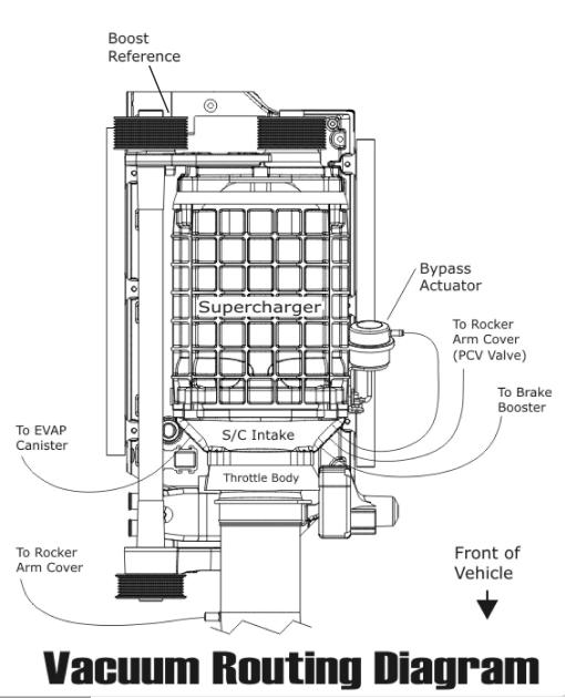
51 193. Verify that your coolant drain is closed, and use a fi lter/strainer to pour the recycled coolant/water mixture that you drained from the ra- diator in steps # 9, 10 back into the radiator Attach the Vacuum routing diagram, inter- cooler-belt routing diagram/information sticker in a conspicuous location. We chose the under- side of the hood Attach the Use Premium Fuel Only de- cal to the gas tank fill cap or door Start the vehicle for fi ve seconds and shut off. Check for fuel leaks and supercharger/en- gine pulley belt alignment. Check the radiator and intercooler reservoir levels, topping off as necessary. 05/11 Page 51


.")
52 197. Test-drive the vehicle for the fi rst few miles under normal driving conditions. Listen for any noises, vibrations, engine misfi re or anything that does not seem normal. The super- charger does have a slight whining noise under boost conditions, this is normal Re-check the radiator and intercooler res- ervoir coolant level regularly over the fi rst 1,000 miles, top off level as needed After the initial test drive, go through the belt tensioner process again (step #147). When next you start driving, gradually work the vehicle to wide open throttle runs. Listen for any en- gine detonation (pinging). If engine detonation is present, let up on the throttle immediately. Most detonation causes are low octane gasoline still in the tank. 05/11 Page 52

53 If you have questions about your vehicles performance, please check with your installation facility or call Magna Charger at (805) , Monday through Friday, 8am to 5pm (Pacifi c Time). Ventura, CA. MagnaCharger, manufacturer of superchargers and supercharger systems for foreign and domestic vehicles, was presented the prestigious award at the annual Specialty Equipment Market Association Show (SEMA in Las Vegas, Nevada. The award was presented for the Radix Intercooled super- charger system, designed for the Chevrolet, GMC and Cadillac, 4.8L, 5.3L and 6.0L Gen- eral Motors Trucks and SUV s including the new H2 and SSR. Sponsored by General Motors Corporation, the SEMA Design Award for the Most Innovative Product was awarded to Magna Charger and recognized by the all-star team of judges for their outstanding and innovative design achievement. The criteria used by the judges included innova- tioin, technical achievement, quality and workmanship. Please enjoy your Magna Charged performance responsibly. 05/11 Page 53

54 05/11 Page 54
SMALL BLOCK CHEVROLET SUPERCHARGER SYSTEM
 Installation Instructions for: SMALL BLOCK CHEVROLET SUPERCHARGER SYSTEM Step-by-step instructions for installing the best in supercharger systems. * PREMIUM FUEL REQUIRED * 89-89-57-008-TF Rev B Magnuson
INTERCOOLED SUPERCHARGER SYSTEM FORD 5.4L 3V F-150 TRUCK
 Installation Instructions for: INTERCOOLED SUPERCHARGER SYSTEM 2004-2006 FORD 5.4L 3V F-150 TRUCK Step-by-step instructions for installing the best in supercharger systems. 89-89-65-001 Rev C Magnuson
Installation Instructions for: Radix. INTERCOOLED SUPERCHARGER SYSTEM 2008 Hummer H3-Alpha
 Installation Instructions for: Radix INTERCOOLED SUPERCHARGER SYSTEM 2008 Hummer H3-Alpha Step-by-step instructions for installing the best in supercharger systems. ATTENTION! Your MAGNA CHARGER intercooler
137. Unbolt the fi ve bolts holding the coil brackets to the valve covers using a 10mm wrench Remove the coil brackets for modifi cation.
 137. Unbolt the fi ve bolts holding the coil brackets to the valve covers using a 10mm wrench. 138. Remove the coil brackets for modifi cation. 139. Use a small fl athead screwdriver to unsnap the plastic
INTERCOOLED SUPERCHARGER SYSTEM Dodge Challenger 6.1 Liter HEMI
 Installation Instructions for: INTERCOOLED SUPERCHARGER SYSTEM 2009+ Dodge Challenger 6.1 Liter HEMI Step-by-step instructions for installing the best in supercharger systems. * PREMIUM FUEL REQUIRED *
Installation Instructions for: Radix. Intercooled Supercharger System GM 4.8L & 5.3L SUV S Only
 Installation Instructions for: Radix Intercooled Supercharger System 07-10 GM 4.8L & 5.3L SUV S Only Step-by-step instructions for installing the best in supercharger systems. * PREMIUM FUEL REQUIRED *
INTERCOOLED SUPERCHARGER SYSTEM PONTIAC G8 GT (6.0L)
") Installation Instructions for: INTERCOOLED SUPERCHARGER SYSTEM 2008-2009 PONTIAC G8 GT (6.0L) Step-by-step instructions for installing the best in supercharger systems. * PREMIUM FUEL REQUIRED * ATTENTION!
Installation Instructions for: INTERCOOLED SUPERCHARGER SYSTEM 2008-2009 PONTIAC G8 GT (6.0L) Step-by-step instructions for installing the best in supercharger systems. * PREMIUM FUEL REQUIRED * ATTENTION!
INTERCOOLED SUPERCHARGER SYSTEM Dodge Challenger 5.7 Liter HEMI
 Installation Instructions for: INTERCOOLED SUPERCHARGER SYSTEM 2009-10 Dodge Challenger 5.7 Liter HEMI Step-by-step instructions for installing the best in supercharger systems. * PREMIUM GASOLINE FUEL
INTERCOOLED SUPERCHARGER SYSTEM 2008 PONTIAC G8
 Installation Instructions for: INTERCOOLED SUPERCHARGER SYSTEM 2008 PONTIAC G8 Step-by-step instructions for installing the best in supercharger systems. * PREMIUM FUEL REQUIRED * ATTENTION! Your MAGNA
Installation Instructions for: JEEP CHEROKEE 6.1 Liter HEMI INTERCOOLED SUPERCHARGER SYSTEM
 Installation Instructions for: 2006-10 JEEP CHEROKEE 6.1 Liter HEMI INTERCOOLED SUPERCHARGER SYSTEM Step-by-step instructions for installing the best in supercharger systems. * PREMIUM FUEL REQUIRED *
Installation Instructions for: Radix Max. Intercooled Supercharger System GM 6.0L & 6.2L TRUCKS
 Installation Instructions for: Radix Max Intercooled Supercharger System 07-13 GM 6.0L & 6.2L TRUCKS Step-by-step instructions for installing the best in supercharger systems. * PREMIUM GASOLINE FUEL REQUIRED
Installation Instructions for: RAM 5.7 Liter HEMI INTERCOOLED SUPERCHARGER SYSTEM
 Installation Instructions for: 2014-2015 RAM 5.7 Liter HEMI INTERCOOLED SUPERCHARGER SYSTEM Step-by-step instructions for installing the best in supercharger systems. * PREMIUM GASOLINE FUEL REQUIRED *
Installation Instructions for: Radix Retro. Intercooled Supercharger System GM 4.8L & 5.3L TRUCKS
 Installation Instructions for: Radix Retro Intercooled Supercharger System 07-10 GM 4.8L & 5.3L TRUCKS Step-by-step instructions for installing the best in supercharger systems. * PREMIUM FUEL REQUIRED
FORD MUSTANG 5.0L
 Installation instructions for: INTERCOOLED SUPERCHARGER SYSTEM 2011-2013 FORD MUSTANG 5.0L Step-by-step instructions for installing the best in supercharger systems. * PREMIUM FUEL REQUIRED * ATTENTION!
Installation Instructions for: Radix. INTERCOOLED SUPERCHARGER SYSTEM L Chevrolet Trailblazer SS
 Installation Instructions for: Radix INTERCOOLED SUPERCHARGER SYSTEM 2006-2007 6.0L Chevrolet Trailblazer SS Step-by-step instructions for installing the best in supercharger systems. ATTENTION! Your MAGNA
Installation Instructions for: Radix Retro. Intercooled Supercharger System GM 4.8L & 5.3L SUV s
 Installation Instructions for: Radix Retro Intercooled Supercharger System 07-13 GM 4.8L & 5.3L SUV s Step-by-step instructions for installing the best in supercharger systems. * PREMIUM GASOLINE FUEL
Installation Instructions for: HOT ROD SUPERCHARGER SYSTEM
 Installation Instructions for: HOT ROD SUPERCHARGER SYSTEM 89-89-57-007 Step-by-step instructions for installing the best in supercharger systems. Magnuson Products Inc 1990 Knoll Drive, Ventura, CA. 93003
Installation Instructions for: CORVETTE SUPERCHARGER SYSTEM 1997 TO 2004 C5 & Z06 CORVETTE
 Installation Instructions for: CORVETTE SUPERCHARGER SYSTEM 1997 TO 2004 C5 & Z06 CORVETTE Step-by-step instructions for installing the best in supercharger systems. * PREMIUM FUEL REQUIRED * ATTENTION!
Installation Instructions for: Radix Retro. Intercooled Supercharger System GM 4.8L & 5.3L TRUCKS
 Installation Instructions for: Radix Retro Intercooled Supercharger System 07-13 GM 4.8L & 5.3L TRUCKS Step-by-step instructions for installing the best in supercharger systems. * PREMIUM GASOLINE FUEL
INTERCOOLED SUPERCHARGER SYSTEM LS3/L99 Chevrolet Camaro
 HeartBeat Installation Instructions for: INTERCOOLED SUPERCHARGER SYSTEM 2013-2015 LS3/L99 Chevrolet Camaro Step-by-step instructions for installing the best in supercharger systems. * PREMIUM GASOLINE
Jeep Wrangler 3.6L V-6 INTERCOOLED SUPERCHARGER SYSTEM
 Installation Instructions for: 2012 + Jeep Wrangler 3.6L V-6 INTERCOOLED SUPERCHARGER SYSTEM PREMIUM GASOLINE FUEL REQUIRED ATTENTION: Your MAGNUSON SUPERCHARGER kit is sensitive to corrosion! Take care
Installation Instructions for: Sierra 5.3/6.2L DI
 Installation Instructions for: INTERCOOLED SUPERCHARGER SYSTEM Step-by-step instructions for installing the best in supercharger systems. * PREMIUM GASOLINE FUEL REQUIRED * ATTENTION! Your MAGNUSON SUPERCHARGER
Installation Instructions for: CORVETTE SUPERCHARGER SYSTEM C6 LS3 CORVETTE
 Installation Instructions for: CORVETTE SUPERCHARGER SYSTEM 2008-2013 C6 LS3 CORVETTE Step-by-step instructions for installing the best in supercharger systems. * PREMIUM FUEL REQUIRED * ATTENTION! Your
Installation Instructions for: Dodge RAM 5.7 Liter HEMI INTERCOOLED SUPERCHARGER SYSTEM
 Installation Instructions for: 2009-2010 Dodge RAM 5.7 Liter HEMI INTERCOOLED SUPERCHARGER SYSTEM Step-by-step instructions for installing the best in supercharger systems. * PREMIUM GASOLINE FUEL REQUIRED
INTERCOOLED SUPERCHARGER SYSTEM 2009 PONTIAC G8 GXP
 Installation Instructions for: INTERCOOLED SUPERCHARGER SYSTEM 2009 PONTIAC G8 GXP Step-by-step instructions for installing the best in supercharger systems. * PREMIUM FUEL REQUIRED * ATTENTION! Your MAGNA
Supercharger System Chevrolet Silverado1500 & GMC Sierra 1500 Light Duty Sport Trucks
 Installation Instructions for: Radix-NI Supercharger System 2003-2006 Chevrolet Silverado1500 & GMC Sierra 1500 Light Duty Sport Trucks 89-89-59-003 Rev C Step-by-step instructions for installing the best
Installation Instructions for: Sierra 5.3/6.2L DI INTERCOOLED SUPERCHARGER SYSTEM
 Installation Instructions for: INTERCOOLED SUPERCHARGER SYSTEM Step-by-step instructions for installing the best in supercharger systems. * PREMIUM GASOLINE FUEL REQUIRED * ATTENTION! Your MAGNUSON SUPERCHARGER
INTERCOOLED SUPERCHARGER SYSTEM PONTIAC GTO LS2
 Installation Instructions for: INTERCOOLED SUPERCHARGER SYSTEM 2005-2006 PONTIAC GTO LS2 Step-by-step instructions for installing the best in supercharger systems. Magnuson Products Inc 1990 Knoll Drive,
Intercooled Supercharger System , 2007 Classic GM Trucks, 4.8L, 5.3L & 6.0L
 Installation Instructions for: Radix Retro Intercooled Supercharger System 2003-2006, 2007 Classic GM Trucks, 4.8L, 5.3L & 6.0L * PREMIUM GASOLINE FUEL REQUIRED * Step-by-step instructions for installing
INTERCOOLED SUPERCHARGER SYSTEM LS3/L99 Chevrolet Camaro
 HeartBeat Installation Instructions for: INTERCOOLED SUPERCHARGER SYSTEM 2010-2012 LS3/L99 Chevrolet Camaro Step-by-step instructions for installing the best in supercharger systems. ATTENTION! Your MAGNUSON
SUPERCHARGER SYSTEM LT1 Chevrolet Camaro
 HeartBeat Installation Instructions for: SUPERCHARGER SYSTEM 2016-2017 LT1 Chevrolet Camaro NON-INTERCOOLED Step-by-step instructions for installing the best in supercharger systems * PREMIUM GASOLINE
Procharger Stage II Intercooled Supercharger System (11-14 GT)
") Procharger Stage II Intercooled Supercharger System (11-14 GT) Installation Time: Approximately one day. Installed on 2012 Mustang GT 5.0/Manual Required Tools 3/8 Socket Set (Standard and Metric) 1/2
Procharger Stage II Intercooled Supercharger System (11-14 GT) Installation Time: Approximately one day. Installed on 2012 Mustang GT 5.0/Manual Required Tools 3/8 Socket Set (Standard and Metric) 1/2
Installation Instructions for: CORVETTE SUPERCHARGER SYSTEM LT4 Z06 CORVETTE
 Installation Instructions for: CORVETTE SUPERCHARGER SYSTEM 2015+ LT4 Z06 CORVETTE Step-by-step instructions for installing the HeartBeat of supercharger systems. * PREMIUM GASOLINE FUEL REQUIRED * ATTENTION!
INTERCOOLED SUPERCHARGER SYSTEM 2004 PONTIAC GTO
 Installation Instructions for: INTERCOOLED SUPERCHARGER SYSTEM 2004 PONTIAC GTO 89-89-60-013 Rev. F Step-by-step instructions for installing the best in supercharger systems. Magnuson Products Inc 1990
Radix. Installation Instructions for: Intercooled Supercharger System Chevrolet Silverado & GMC Sierra Trucks Suburban 2500 & Yukon XL 2500
 Installation Instructions for: Radix Intercooled Supercharger System 1999-2002 Chevrolet Silverado & GMC Sierra Trucks Suburban 2500 & Yukon XL 2500 * PREMIUM GASOLINE FUEL REQUIRED * ATTENTION! Your MAGNUSON
Installation Instructions for: Radix. Intercooled Supercharger System Avalanche 1500, Tahoe 1500, Suburban 1500 & Yukon 1500
 Installation Instructions for: Radix Intercooled Supercharger System 2003-2006 Avalanche 1500, Tahoe 1500, Suburban 1500 & Yukon 1500 PREMIUM GASOLINE FUEL REQUIRED Step-by-step instructions for installing
Installation Instructions for: Toyota 4Runner and FJ Cruiser
 Installation Instructions for: 2010-2017 Toyota 4Runner and 2010-2014 FJ Cruiser Step-by-step instructions for installation of the supercharger system. * PREMIUM GASOLINE FUEL REQUIRED * ATTENTION! Your
Installation Instructions for: Radix. Intercooled Supercharger System
 Installation Instructions for: Radix Intercooled Supercharger System 2003-2006, 2007 Classic Chevrolet Silverado & GMC Sierra Trucks Suburban 2500, Yukon XL 2500 & Avalanche 2500 * PREMIUM GASOLINE FUEL
Installation Instructions for: TOYOTA 4.5L SUPERCHARGER SYSTEM
 Installation Instructions for: TOYOTA 4.5L SUPERCHARGER SYSTEM 1995-1997 Land Cruiser * PREMIUM FUEL REQUIRED * Magnuson Products LLC 1990 Knoll Drive, Bldg A, Ventura, CA 93003 (805) 642-8833 phone *
2006 Honda Civic SI Supercharger Kit Installation Instruction Kit #
 2006 Honda Civic SI Supercharger Kit Installation Instruction Kit #350-091 3239 MONIER CIRCLE, STE.5 RANCHO CORDOVA, CA 95742 916.635.4550 FAX 916.635.4632 www.ct-engineering.com INS-157 VERSION: 3.25.2009
Installation Instructions for: Radix. Intercooled Supercharger System Avalanche 1500, Tahoe 1500, Subruban 1500 & Yukon 1500
 Installation Instructions for: Radix Intercooled Supercharger System 2003-2006 Avalanche 1500, Tahoe 1500, Subruban 1500 & Yukon 1500 89-89-60-003 Rev I Step-by-step instructions for installing the best
SLP Camaro ZL1 STAGE 3 (650 HP)
") SLP - 2012 Camaro ZL1 STAGE 3 (650 HP) PART #26002 PACKING LIST Before installation, use this check list to make sure all necessary parts have been included. ITEM QTY CHECK PART NUMBER DESCRIPTION 1. 1
SLP - 2012 Camaro ZL1 STAGE 3 (650 HP) PART #26002 PACKING LIST Before installation, use this check list to make sure all necessary parts have been included. ITEM QTY CHECK PART NUMBER DESCRIPTION 1. 1
Installation Instructions for: INTERCOOLED SUPERCHARGER SYSTEM CADILLAC CTS-V
 Installation Instructions for: INTERCOOLED SUPERCHARGER SYSTEM 2004-2005 CADILLAC CTS-V Rev. A Step-by-step instructions for installing the best in supercharger systems. Magnuson Products Inc 3172 Bunsen
Edelbrock E-Force Supercharger Part #1538: Dodge 1500 Truck 5.7L V8 HEMI
 Edelbrock E-Force Supercharger Part #1538: 2009-2014 Dodge 1500 Truck 5.7L V8 HEMI 2009-14 Dodge 5.7L Hemi 1500 Truck INTRODUCTION Thank you for purchasing the Edelbrock Supercharger System for the 2009-15
INTERCOOLED SUPERCHARGER SYSTEM CADILLAC CTS-V
 Installation Instructions for: INTERCOOLED SUPERCHARGER SYSTEM 2004-2005 CADILLAC CTS-V 89-89-60-015 Rev C Step-by-step instructions for installing the best in supercharger systems. Magnuson Products Inc
Installation Instructions for: Toyota Tundra 5.7L
 Installation Instructions for: 2009-2015 Toyota Tundra 5.7L -For Flex Fuel Trucks- Step-by-step instructions for installation of the supercharger system. * PREMIUM GASOLINE FUEL REQUIRED* *NOT COMPATIBLE
Instructions for: Toyota 5.7L Coupler Replacement
 Instructions for: Toyota 5.7L Coupler Replacement * PREMIUM GASOLINE FUEL REQUIRED * ATTENTION! Your MAGNUSON SUPERCHARGER kit is sensitive to corrosion! Use only the vehicle manufacturer recommended coolant
4. Remove (4) 10mm and (1) 7mm bolt that holds fascia at front corners, on each side
 10mm and (1) 7mm bolt that holds fascia at front corners, on each side") 2010 Camaro LS3 1. Disconnect battery ground 2. Remove front wheels 3. Remove (5) push pins and (5) #20 torx screws on inner front wheel well liners and remove liners on each side 4. Remove (4) 10mm and
2010 Camaro LS3 1. Disconnect battery ground 2. Remove front wheels 3. Remove (5) push pins and (5) #20 torx screws on inner front wheel well liners and remove liners on each side 4. Remove (4) 10mm and
Huron Speed Products Twin Turbo Install Gen 2 CTS-V (09-15)
") Huron Speed Products Twin Turbo Install Gen 2 CTS-V (09-15) The following install guide is simply that, a guide to help you with installation. It is by no means the exact method to perform installation,
Huron Speed Products Twin Turbo Install Gen 2 CTS-V (09-15) The following install guide is simply that, a guide to help you with installation. It is by no means the exact method to perform installation,
Installation Instructions for: TOYOTA 3.4L SUPERCHARGER SYSTEM
 Installation Instructions for: TOYOTA 3.4L SUPERCHARGER SYSTEM 1996-2002 4Runner 1997-1998 T100 1997-2004 Tacoma 2000-2003 Tundra * PREMIUM FUEL REQUIRED * Magnuson Products LLC 1990 Knoll Drive, Bldg
Huron Speed Products Twin Turbo Install Gen 2 CTS-V (09-15)
") Huron Speed Products Twin Turbo Install Gen 2 CTS-V (09-15) 1 2 Remove two bolts in trunk cover with 8mm socket. Pull up on cover to remove. Unscrew net tie down on side cover where battery is located
Huron Speed Products Twin Turbo Install Gen 2 CTS-V (09-15) 1 2 Remove two bolts in trunk cover with 8mm socket. Pull up on cover to remove. Unscrew net tie down on side cover where battery is located
Installation Instructions for: CORVETTE SUPERCHARGER SYSTEM C7 LT1 CORVETTE
 Installation Instructions for: CORVETTE SUPERCHARGER SYSTEM 2014-2017 C7 LT1 CORVETTE Step-by-step instructions for installing the HeartBeat of supercharger systems. * PREMIUM GASOLINE FUEL REQUIRED *
INTERCOOLED SUPERCHARGER SYSTEM Dodge Challenger 6.4 Liter HEMI
 Installation Instructions for: INTERCOOLED SUPERCHARGER SYSTEM 2011+ Dodge Challenger 6.4 Liter HEMI Step-by-step instructions for installing the best in supercharger systems. * PREMIUM FUEL REQUIRED *
Intercooled Supercharger System Chevrolet Silverado & GMC Sierra Trucks Suburban 2500,Yukon XL 2500
 Installation Instructions for: Radix Intercooled Supercharger System 1999-2002 Chevrolet Silverado & GMC Sierra Trucks Suburban 2500,Yukon XL 2500 89-89-60-001 Rev. F Step-by-step instructions for installing
LChevrolet Camaro Supercharger Kit
 PART #92000A Important Notes: 2010-2013 6.2LChevrolet Camaro Supercharger Kit The use of fuel additives (ie. octane boosters) is not recommended. There is a possibility that these chemicals can damage
Slingshot Rotrex Supercharger Kit
 Slingshot Rotrex Supercharger Kit This supercharger kit improves on the Slingshot by forcing more dense air into the engine and creating more power. Installation time of the supercharger depends on you
Installation Instructions for: Toyota Tacoma 4.0L
 Installation Instructions for: 2005-2015 Toyota Tacoma 4.0L Step-by-step instructions for installation of the supercharger system. * PREMIUM GASOLINE FUEL REQUIRED * ATTENTION! Your MAGNUSON SUPERCHARGER
Weistec M113K Supercharger System Installation Guide
 Weistec M113K Supercharger System Installation Guide WARNING! DO NOT HAVE YOUR ECU REPROGRAMMED ANYWHERE BUT AT WEISTEC FOR THIS SUPERCHARGER. THE AMG 55 USES AN ELECTRONIC THROTTLE CONTROL (ETC), WHICH
Phone Fax
 Directions for Installation of ECS Paxton Supercharger Kit Disconnect battery Remove stock serpentine belt Remove stock belt tensioner, save the 2 bolts for later use on supercharger bracket Remove alternator
Installation Instructions for Lingenfelter GM 2500 Suburban & Yukon XL Auxiliary Fan System (with AC clutch controlled fan output)
") Installation Instructions for Lingenfelter 2007-2013 GM 2500 Suburban & Yukon XL Auxiliary Fan System (with AC clutch controlled fan output) PN L300080607 Revision - 1.1 Lingenfelter Performance Engineering
Installation Instructions for Lingenfelter 2007-2013 GM 2500 Suburban & Yukon XL Auxiliary Fan System (with AC clutch controlled fan output) PN L300080607 Revision - 1.1 Lingenfelter Performance Engineering
Installation Instructions for: Toyota Tundra 5.7L -Not for Flex Fuel Trucks-
 Installation Instructions for: 2007-2015 Toyota Tundra 5.7L -Not for Flex Fuel Trucks- Step-by-step instructions for installation of the supercharger system. * PREMIUM GASOLINE FUEL REQUIRED * ATTENTION!
Installation Instructions for: Toyota Tundra 5.7L -Not for Flex Fuel Trucks-
 Installation Instructions for: 2007-2017 Toyota Tundra 5.7L -Not for Flex Fuel Trucks- Step-by-step instructions for installation of the supercharger system. * PREMIUM GASOLINE FUEL REQUIRED * ATTENTION!
Installation Instructions for: Audi S4 V6 (B8, B8.5) & S5 (B8.5)
 & S5 (B8.5)") Installation Instructions for: Audi S4 V6 (B8, B8.5) & S5 (B8.5) Step-by-step instructions for installation of the supercharger system. * PREMIUM GASOLINE FUEL REQUIRED * ATTENTION! Your MAGNUSON SUPERCHARGER
Installation Instructions for: Audi S4 V6 (B8, B8.5) & S5 (B8.5) Step-by-step instructions for installation of the supercharger system. * PREMIUM GASOLINE FUEL REQUIRED * ATTENTION! Your MAGNUSON SUPERCHARGER
#TL T EA888 GEN 3 FUELING SYSTEM/ INSTALLATION INSTRUCTIONS
 #TL100069 2.0T EA888 GEN 3 FUELING SYSTEM/ INSTALLATION INSTRUCTIONS Notes: These instructions were written for a North American specification MkVII GTI. Other models, like the Golf R, are similar. When
ENGINE DEVELOPMENT INC.
 2003 Ford Expedition 4.6L& 5.4L We encourage you to read this manual thoroughly before you begin work, and perform the following: 1. A quick parts check to make certain your kit is complete. If you discover
03-04 Mach 1. Hellion Power Systems Mach 1 Kit Instructions
 Hellion Power Systems 03-04 Mach 1 Kit Instructions Part 1 Hellion recommends that the front suspension system be installed either by trained professionals or by 5.Remove rack bolts K-Member Installation
Edelbrock E-Force Supercharger Dodge/Chrysler 5.7L and 6.4L HEMI Part #1534, 1535, and 15350
 Edelbrock E-Force Supercharger 2011-2013 Dodge/Chrysler 5.7L and 6.4L HEMI Part #1534, 1535, 15340 and 15350 PLEASE COMPLETE THIS PROCEDURE PRIOR to starting the installation of your E-Force supercharger
Always wear safety glasses when working on your vehicle.
 90-93 MAZDA MIATA SUPERCHARGER KIT The KraftWerks 90-93 Mazda Miata Supercharger Kit was designed for easy installation. Competent mechanics with the appropriate tools will find the process to be relatively
SL63 Weistec M156 Supercharger System Installation Guide Stage 1 / Stage 2
 SL63 Weistec M156 Supercharger System Installation Guide Stage 1 / Stage 2 WARNING! DO NOT HAVE YOUR ECU REPROGRAMMED ANYWHERE BUT AT WEISTEC FOR THIS SUPERCHARGER. THE AMG 63 USES AN ELECTRONIC THROTTLE
05-08 GT. Hellion Power Systems Mustang Kit Instructions
 Hellion Power Systems 05-08 Mustang Kit Instructions 1. Disconnect Battery 2. Drain Radiator, keep fluid for re-installation. 3. Remove air box and inlethoses. 6. Next, underneath, punch oil pan for turbo
Edelbrock 5.0L Mustang GT Supercharger Part #1588 & 1589
 Edelbrock 5.0L Mustang GT Supercharger Part #1588 & 1589 INTRODUCTION Edelbrock 5.0L Ford Supercharger System Thank you for purchasing the Edelbrock 5.0L Ford Supercharger System for the Mustang GT. The
V1 Truck Manifold Turbo Kit for F-body
 V1 Truck Manifold Turbo Kit for 98-02 F-body Prep: -Remove all A/C Components, Alternator and brackets, tensioner, front bumper, front bumper foam, and front bumper support. Remove radiator and cooling
ADM Performance 6079 Mapleshade Lane Dallas, Texas (214)
") 1) Disconnect Battery Ground 2) Raise front end of Vehicle FAN INSTALL INSTRUCTIONS 3) Remove lower Radiator hose and drain coolant into a pan. (you will reuse coolant later) 4) Remove Air Intake piping
1) Disconnect Battery Ground 2) Raise front end of Vehicle FAN INSTALL INSTRUCTIONS 3) Remove lower Radiator hose and drain coolant into a pan. (you will reuse coolant later) 4) Remove Air Intake piping
Installation Manual v1.0: Aurora Plus Turbo Kit ( ) 5.9L Dodge. Please read all instructions before installation.
 5.9L Dodge. Please read all instructions before installation.") Installation Manual v1.0: Aurora Plus - 4000 Turbo Kit (2003-2007) 5.9L Dodge Please read all instructions before installation. Figure 1: Aurora Plus - 4000 Kit Contents 1 Figure 2: Aurora Plus Hardware
Installation Manual v1.0: Aurora Plus - 4000 Turbo Kit (2003-2007) 5.9L Dodge Please read all instructions before installation. Figure 1: Aurora Plus - 4000 Kit Contents 1 Figure 2: Aurora Plus Hardware
Z06 Corvette Lingenfelter High Flow Air Intake
 2006-2007 Z06 Corvette Lingenfelter High Flow Air Intake LN4233 1557 Winchester Road Decatur, Indiana 46733 260 724 2552 phone 260 724 8761 fax www.lingenfelter.com Parts List # Part number Description
Edelbrock Victor II Intake Manifold. For Chrysler 5.7L (Eagle), 6.1L and 6.4L Gen III HEMI Engines Part #7179
, 6.1L and 6.4L Gen III HEMI Engines Part #7179") For Chrysler 5.7L (Eagle), 6.1L and 6.4L Gen III HEMI Engines PLEASE study these instructions carefully before beginning this installation. You should be familiar with and comfortable working on your
For Chrysler 5.7L (Eagle), 6.1L and 6.4L Gen III HEMI Engines PLEASE study these instructions carefully before beginning this installation. You should be familiar with and comfortable working on your
Suggested Installation Instructions for: Chevrolet Z06 Corvette Lingenfelter High Flow Air Intake System (7.
 Page 1 Suggested Installation Instructions for: 638-878 2006-2008 Chevrolet Z06 Corvette Lingenfelter High Flow Air Intake System (7.0L LS7 V8 engine) Count on Mid America Motorworks for all your Corvette
Edelbrock Hemi Supercharger Part #1530, 1531, 1532, 1533, 1536 & 1537
 Edelbrock Hemi Supercharger INTRODUCTION Thank you for purchasing the Edelbrock Hemi Supercharger System for various Chrysler/Dodge vehicles. The Edelbrock E-Force Supercharger System for the 2005 to 2010
LML 3 Y-Bridge Kit or High Flow Intake Bundle Package
 2011-2016 LML 3 Y-Bridge Kit or High Flow Intake Bundle Package Covers installation of PN s: WCF100607, WCF100691, WCF100716, & WCF100353 Note: This Kit is for off road competition use only! Overview-
CLS63 Weistec M156 Supercharger System Installation Guide Stage 1 / Stage 2
 CLS63 Weistec M156 Supercharger System Installation Guide Stage 1 / Stage 2 WARNING! DO NOT HAVE YOUR ECU REPROGRAMMED ANYWHERE BUT AT WEISTEC FOR THIS SUPERCHARGER. THE AMG 63 USES AN ELECTRONIC THROTTLE
2015 Corvette Supercharger System Instructions
 2015 Corvette Supercharger System Instructions These instructions are meant to serve as a guide to the installation of the ECS 2015 Corvette Supercharging system. Please be sure to use all safety equipment
ENGINE ASSEMBLY STOCK TO 250 HP
 GM SPORT COMPACT Performance Build Book 25 ENGINE ASSEMBLY STOCK TO 250 HP Fig. 3 The stock ECOTEC engine has proven reliable to 250 hp.(fig. 3) Performance upgrades are available from GM Performance Parts
INSTALLATION INSTRUCTIONS STILLEN SUPERCHARGER KIT Nissan 350Z P/N &
 Equipment needed: 1. Assorted sockets and wrenches 2. +,- Screwdrivers 3. Assorted pliers/ Clamps 4. Wire cutting/crimping tools 5. Thread locking compound (blue) 6. Solder gun/ shrink wrap (optional)
7 th Gen. Celica GTS Turbo Kit Installation Guide This kit has not been CARB approved and is intended for racing / offroad purposes only.
 7 th Gen. Celica GTS Turbo Kit Installation Guide This kit has not been CARB approved and is intended for racing / offroad purposes only. The purpose of this guide is to serve as a reference for use when
Disconnect the APP sensor harness connector. See Fig. 4. Remove the accelerator pedal mounting nuts. Remove the APP assembly.
 ENGINE CONTROLS - REMOVAL, OVERHAUL & INSTALLATION - 6.6L DIESEL... Page 1 of 41 FUEL SYSTEMS ACCELERATOR PEDAL POSITION SENSOR Removal & Installation Disconnect the APP sensor harness connector. See Fig.
Edelbrock E-Force Supercharger Stage II System Ford Mustang 4.6L Part # s: 15856
 2005-2009 Ford Mustang 4.6L Part # s: 15856 INTRODUCTION Thank you for purchasing the Edelbrock 4.6L Ford Supercharger System for the Mustang GT. The Edelbrock E-Force Supercharger System for the 2005-2009
99-04 GT. Hellion Power Systems Mustang GT Kit Instructions
 Hellion Power Systems 99-04 Mustang GT Kit Instructions Part 1 Hellion recommends that the front suspension system be installed either by trained professionals or by 5.Remove rack bolts K-Member Installation
Installation Manual v1.0: MST Turbo Kit ( ) 5.9L Dodge. Please read all instructions before installation.
 5.9L Dodge. Please read all instructions before installation.") Installation Manual v1.0: MST Turbo Kit (2003-2007) 5.9L Dodge Please read all instructions before installation. Figure 1: MST Kit Contents Figure 2: MST Hardware Kit Please make sure all of the components
Installation Manual v1.0: MST Turbo Kit (2003-2007) 5.9L Dodge Please read all instructions before installation. Figure 1: MST Kit Contents Figure 2: MST Hardware Kit Please make sure all of the components
Installation Instructions for: Radix Intercooled Supercharger System 2003 & 2004 GM SUV (Avalanche Denali, Tahoe, Suburban & Yukon)
") Installation Instructions for: Radix Intercooled Supercharger System 2003 & 2004 GM SUV (Avalanche Denali, Tahoe, Suburban & Yukon) Step-by-step instructions for installing the best in supercharger systems.
Installation Instructions for: Radix Intercooled Supercharger System 2003 & 2004 GM SUV (Avalanche Denali, Tahoe, Suburban & Yukon) Step-by-step instructions for installing the best in supercharger systems.
SLS825 Weistec Supercharger System Installation Guide
 SLS825 Weistec Supercharger System Installation Guide 2010-Present SLS AMG (Gullwing and Roadster) 2014 SLS Black Series WARNING! DO NOT HAVE YOUR ECU REPROGRAMMED ANYWHERE BUT AT WEISTEC FOR THIS SUPERCHARGER.
Edelbrock Victor II Intake Manifold. For Chrysler 5.7L (Eagle) and 6.1L Gen III HEMI Engines Part #7179
 and 6.1L Gen III HEMI Engines Part #7179") For Chrysler 5.7L (Eagle) and 6.1L Gen III HEMI Engines PLEASE study these instructions carefully before beginning this installation. You should be familiar with and comfortable working on your vehicle.
For Chrysler 5.7L (Eagle) and 6.1L Gen III HEMI Engines PLEASE study these instructions carefully before beginning this installation. You should be familiar with and comfortable working on your vehicle.
Edelbrock LS3 Corvette Supercharger Part #1590, 1591 & 1592
 Edelbrock LS3 Corvette Supercharger Part #1590, 1591 & 1592 INTRODUCTION Thank you for purchasing the Edelbrock 6.2L GM Superchager System for the Chevy Corvette. The Edelbrock E-Force Supercharger System
Edelbrock E-Force Stage II Supercharger CHEVY CORVETTE C7 Z06 LT4 6.2L Part #157320
 2015-16 CHEVY CORVETTE C7 Z06 LT4 6.2L Part #157320 INTRODUCTION Thank you for purchasing the Edelbrock Stage II Supercharger System for the 2015-16 Chevy Corvette Z06 LT4. The Edelbrock E-Force Supercharger
INSTALLATION INSTRUCTIONS
 INSTALLATION INSTRUCTIONS Part# 69-0717 AIR IT UP 4 Tire On Board Installed Air Delivery System with Rear Mounted Controller (Requires External Air Source) For the most up-to-date instructions please visit
Installation manual BMW E TS1/TS2
 Installation manual BMW E46 330 TS1/TS2 Technical support Europe: +4741558555 Technical support USA: (858)314-2954 Email support: support@esstuning Installation manual BMW E46 330 TS1/TS2 Remove and send
Installation Instructions for Chevrolet Corvette Lingenfelter High Flow Air Intake System (6.0L LS2 V8 engine)
") Installation Instructions for 2005-2007 Chevrolet Corvette Lingenfelter High Flow Air Intake System (6.0L LS2 V8 engine) PN: L650070105 1557 Winchester Road Decatur, Indiana 46733 260 724 2552 phone 260
Installation Instructions for 2005-2007 Chevrolet Corvette Lingenfelter High Flow Air Intake System (6.0L LS2 V8 engine) PN: L650070105 1557 Winchester Road Decatur, Indiana 46733 260 724 2552 phone 260
Edelbrock E-Force Supercharger Complete Competition Ford Mustang 5.0L Part # s: 15896
 Edelbrock E-Force Supercharger Complete Competition Part # s: 15896 Introduction Thank you for purchasing the Edelbrock Complete Competition Supercharger System for the 2011-2013 5.0L Ford Mustang GT.
Special Note About The JDM High Performance Water Pump:
 Page 1 of 30 JDM Engineering, Inc. home Call Us! 732-780- 0770 back to Installation Instructions Electric Fan Upgrade Kit Electric Fan Wiring Diagram Thank you for your purchase of the JDM Engineering
BEFORE BEGINNING INSTALLATION
 COMPLETE CHASSIS FUEL LINE KITS For 1996-2000 Honda Civic Equipped with B-Series Engine INSTALLATION INSTRUCTIONS PLEASE study these instructions carefully before beginning this installation. Most installations
WARNING: ALWAYS relieve fuel pressure before disconnecting any fuel related component. DO NOT allow fuel to contact engine or electrical components.
 4.0L V8 - VINS [K,U] Selected Block 1990 Lexus LS 400 For Lextreme Powertrain 2020 S. Hacienda Blvd. # D Hacienda Heights California 91745 Copyright 1998 Mitchell Repair Information Company, LLC Friday,