Linear Motion Systems Toll Free Phone: Toll Free Fax:
|
|
|
- Ashlie Cameron
- 5 years ago
- Views:
Transcription


1 Linear Motion Systems

2 Thomson - the Choice for Optimized Motion Solutions Often the ideal design solution is not about finding the fastest, sturdiest, most accurate or even the least expensive option. Rather, the ideal solution is the optimal balance of performance, life and cost. Quickly Configure the Optimal Mechanical Motion Solution Thomson has several advantages that makes us the supplier of choice for motion control technology. Thomson owns the broadest standard product offering of mechanical motion technologies in the industry. Modified versions of standard product or white sheet design solutions are routine for us. Choose Thomson and gain access to over 70 years of global application experience in industries including packaging, factory automation, material handling, medical, clean energy, printing, automotive, machine tool, aerospace and defense. As part of Fortive Corporation, we are financially strong and unique in our ability to bring together control, drive, motor, power transmission and precision linear motion technologies. A Name You Can Trust A wealth of product and application information as well as 3D models, software tools, our distributor locator and global contact information is available at /contact_us. Talk to us early in the design process to see how Thomson can help identify the optimal balance of performance, life and cost for your next application. And, call us or any of our distribution partners around the world for fast delivery of replacement parts. The Fortive Business System The Fortive Business System (FBS) was established to increase the value we bring to customers. It is a mature and successful set of tools we use daily to continually improve manufacturing operations and product development processes. FBS is based on the principles of Kaizen which continuously and aggressively eliminates waste in every aspect of our business. FBS focuses the entire organization on achieving breakthrough results that create competitive advantages in quality, delivery and performance advantages that are passed on to you. Through these advantages Thomson is able to provide you faster times to market as well as unsurpassed product selection, service, reliability and productivity. Local Support Around the Globe Application Centers Global Manufacturing Operations Global Design & Engineering Centers
3 Linear Motion Systems Table of Contents Thomson... 5 Linear Motion Systems at Work...6 Simple Product Selection with Linear Motioneering...7 Linear Motion System Group Selection Chart Linear Motion Systems with Lead or Ball Screw Drive and Ball Guide...0 Overview WM40S WM40D WM60D WM60S WM60X WM80D WM80S WM20D WV WV WV MLSM60D MLSM80D M M M HB HB RB RB MS MS Units with inch interface 2DB DB2O DB2J DB6O DB6J Linear Motion Systems with Ball Screw Drive and Slide Guide...68 Overview M M M Linear Motion Systems with Belt Drive and Ball Guide...76 Overview WH WM60Z WM80Z, standard carriage WM80Z, short carriage M M M MLSM80Z Linear Motion Systems with Belt Drive and Slide Guide...94 Overview M M M M Linear Motion Systems with Belt Drive and Wheel Guide...04 Overview WH WH WH MLSH60Z Linear Lifting Units...4 Overview WHZ WHZ Z Z Linear Rod Units...24 Overview WZ WZ Accessories...3 Accessory Index...3 Mounting Kits Cover and Protection Kits Motors, Gears and Transmission Kits Electrical Feedback Devices Non-driven Units Additional Technical Data...78 Additional Technical Data Tables Drive Calculations Deflection Calculations Ordering Keys...87 Keys for Units with Lead or Ball Screw Drive and Ball Guides Keys for Units with Ball Screw Drive and Slide Guides...95 Keys for Units with Belt Drive and Ball Guides Keys for Units with Belt Drive and Slide Guides Keys for Units with Belt Drive and Wheel Guides Keys for Linear Lifting Units Keys for Linear Rod Units Keys for Non-driven Units Terminology Basic Linear Motion System Terminology Glossary A - Belt D Belt G - C D - E...20 G - M...2 N - Sc...22 Si - W

4 4

5 Linear Motion Systems Thomson The optimal balance of performance, life and cost The unmatched breadth of the Thomson linear motion system product line comes from the consolidation of three world-reknowned brands: Thomson, Neff and Tollo. We are product innovators with decades of application experience. Unbiased ownership of the multiple motion system technologies enables Thomson to provide you with the optimal balance of performance versus installed cost for your application. Neff Thomson Thomson Tollo Thomson introduced the first ball screw actuator into an aviation application in 939 and invented the anti-friction Linear Ball Bushing Bearing in 945. Thomson has been a market leader with an increasing portfolio of linear motion technologies ever since. Founded in 905, Neff offered products for the linear motion market and, over the decades, became a market leader in ball screw technology. The first linear motion system from Neff was presented in 98 at the FAMETA show in Stuttgart. Thomson has consolidated the most competitive and complementary products from each brand into the most advanced, most comprehensive product portfolio available today. The range covers the smallest and most compact linear motion systems to the biggest and most robust. Our wide range of guide and drive systems can be configured economically and can also work in harsh environments, at high speeds, and in high precision applications. Thomson is linear motion, optimized. Tollo began in 98 as a lifting equipment manufacturer. The product line grew rapidly thereafter and, in 982, Tollo presented their first linear motion system at the Technical Fair in Stockholm. 5


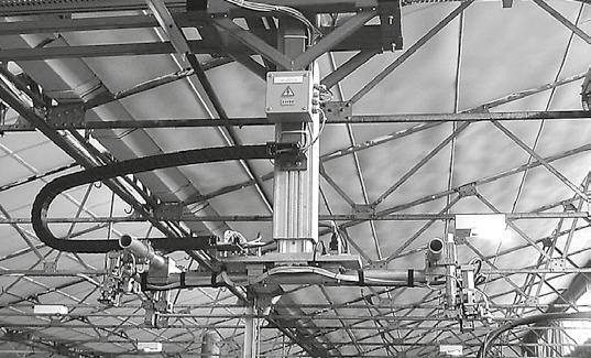
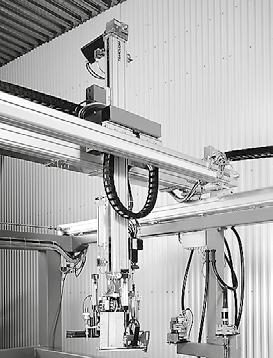
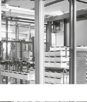
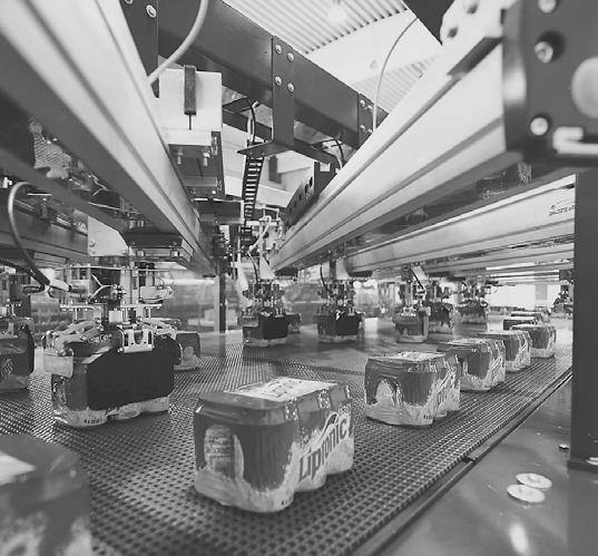
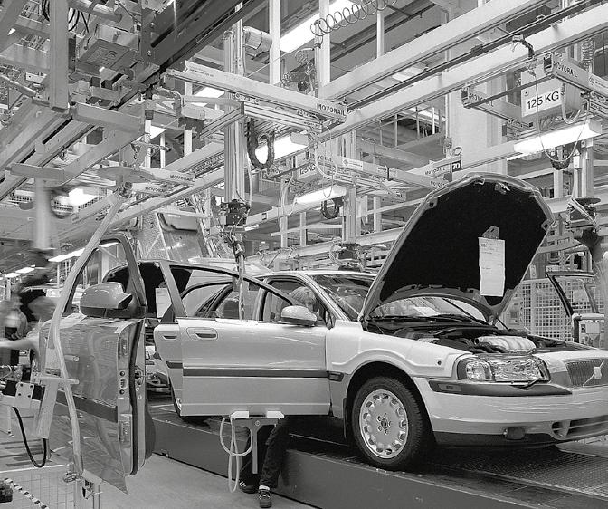
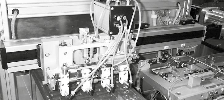
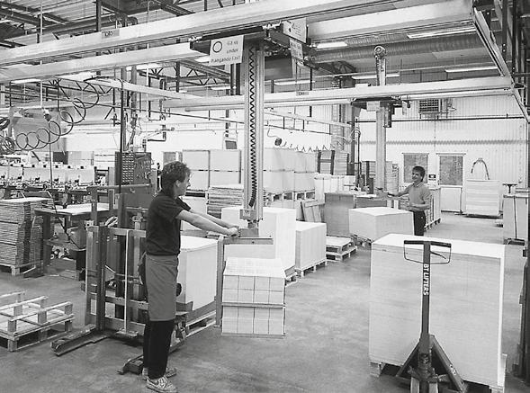
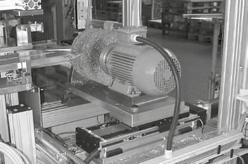
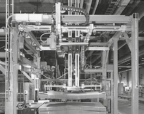
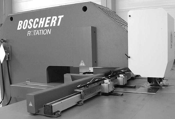
6 Linear Motion Systems at Work Application Examples Thomson Linear Motion Systems can be used in almost all industries. The breadth of our range makes it possible to find the optimum solution for most applications imaginable. If the standard range is not enough, Thomson is happy to discuss a custom solution that meets your needs. Below is a small selection of applications where linear motion systems have been used successfully. Contact us and we can show you many, many more. Handling Linear motion systems are ideal for handling applications. Thomson has units suitable for the harsh environments in food and paper industries to the rigorous cleanliness demands found in the medical and electronics industries. Medical and laboratory In this application a robot made of linear motion systems is used to pick samples from test tubes of different heights. Thomson has the small, quiet, quick and accurate units you need to build this type of equipment. Transportation and transfer Packaging, filling and dispensing Whenever you may need to move something from Sold & one Serviced place By: To fill, close, stack, label or print on boxes or other to another a linear motion system can be the answer. containers of almost any size and weight is easily done Here a molding machine is fed and emptied at high speed. with linear motion systems. 6
7 Linear Motion Systems Simple Product Selection with Linear Motioneering On-Line Product Selection The Linear Motioneering sizing and selection tool is designed to make it simple to choose the right linear motion system for your application. Linear Motioneering is very easy to use, just enter the basic parameters for your application and watch as Linear Motioneering does all the work. Linear Motioneering calculates application parameters through a comprehensive set of algorithms and compares your results to our product database to determine an optimized solution set. To determine which linear motion system is best suited for your application you just enter the application parameters in seven simple steps into Linear Motioneering. Once a product solution is selected, choose from a wide assortment of accessories, motors, and motor mounts. The program will output a 2D drawing or an interactive 3D model, list prices, delivery times, and ordering information. In your account you can see your quote history. Please visit for more information. 7
8 Linear Motion System Group Selection Chart How to select appropriate product group Thomson linear motion systems offers two drive options (screw or belt drive) and three carriage guidance options (ball, slide or wheel guides). The chart below provides reference to the ideal product combination based on the general application type. Application Type Group Instrumentation and other low-load applications. Repeatability and/or spatial constraints may be critical. Small-scale material handling Medical instrumentation Lab automation Vending machines Load < 5 kg Smallest spatial footprint Repeatability ± 0,005 mm Stroke up to 0,7 m Repeatability ± 0,05 mm Speeds up to 3 m/s Strokes up to 2 m Type: MS Drive: Screw Guides: Ball See pages Type: WH40 Drive: Belt Guides: Ball See pages Application Type Group 2 Economical point-to-point transport motion. Speed and/or environmental protection may be critical. Packaging Filling and dispensing Factory automation Material handling Printing and scanning Food processing Repeatability ± 0,05 mm Speeds up to,6 m/s Strokes up to 6 m Repeatability ± 0,2 mm Speeds up to 5 m/s Strokes up to 2 m Type: M Drive: Screw Guides: Slide See pages Type: M Drive: Belt Guides: Slide See pages Application Type Group 3 Motion with tighter accuracy requirements. Stiffness and rigidity may be critical. Machine tool material handling Machine tool automation Test and measurement Inspection equipment Automotive assembly Repeatability < ± 0,02 mm Type: WM Drive: Screw Guides: Ball See pages
9 Linear Motion Systems Linear Motion System Group Selection Chart How to select appropriate product group How to use the selection chart. Chose the one of the three general application type groups that match your application the best. 2. Move right in the chart until you identified a possible unit type for your needs. 3. Look up the unit type in the catalog and see if there is a size or version among them that match. 4. If you find a match, go to step 5. If not, go back to the chart and identify the next possible unit type and repeat. 5. Confirm the choice by performing the necessary calculations. The Linear Motioneering Sizing and Selection Tool or the Thomson customer support team can help you with this. Cost indicator legend Lowest cost Highest cost Type: WM40 Drive: Screw Guides: Ball Repeatability ± 0,0 mm Better stiffness See pages 4-7 Type: 2DB Drive: Screw Guides: Ball Heavier loads Better stiffness Heavier loads Better stiffness Type: M Drive: Screw Guides: Ball See pages Type: M Drive: Belt Guides: Ball Higher moment loads Speeds up to 0 m/s and/or higher moment loads See pages Type: WH, Drive: Belt Guides: Wheel MLSH60Z See pages 06-3 See pages 86-9 Type: 2RB Drive: Screw Guides: Ball Speeds up to 5 m/s and/or higher moment loads Type: WMZ, Drive: Belt Guides: Ball MLSM80Z Best accuracy Repeatability < ± 0,005 mm See pages Best accuracy with higher stiffness and moment load capacity See pages 80-85, Type: 2HB Drive: Screw Guides: Ball Type: MLSM Drive: Screw Guides: Ball Heavier loads and/or higher moments See pages See pages

![screw support system WM40S WM40D WM60D WM60S WM60X WM80D WM80S WM20D Profile size (width height) [mm] 40 40](/docs-images/92/109679886/images/10-2.jpg "40 40 60 60 60 60 60 60 80 80 80 80 20 20 Stroke length (Smax), maximum [mm] 2000 950 000 0390 0340 000")
![0540 000 Linear speed, maximum [m/s] 0,25 0,25 2,5 2,5 0,25 2,5 2,5 2,0 Dynamic carriage load (Fz), maximum](/docs-images/92/109679886/images/10-3.jpg "[N] 600 600 2000 400 2000 3000 200 6000 Remarks single ball nut double ball nuts double ball nuts single")


10 Linear Motion Systems with Ball Screw Drive and Ball Guide Overview PowerLine WM WM40 Features Can be installed in any orientation Patented guide system Patented self-adjusting plastic cover band Patented screw support system WM40S WM40D WM60D WM60S WM60X WM80D WM80S WM20D Profile size (width height) [mm] Stroke length (Smax), maximum [mm] Linear speed, maximum [m/s] 0,25 0,25 2,5 2,5 0,25 2,5 2,5 2,0 Dynamic carriage load (Fz), maximum [N] Remarks single ball nut double ball nuts double ball nuts single ball nut left/right screw double ball nuts single ball nut double ball nuts Page Not on WM40 units WM-Series Technical Presentation Screw support Patented screw support system permits high speeds at long stroke lengths while reducing the available stroke with a minimum. Double ball nuts Double pre-tensioned ball nuts improve the accuracy and allow re-tensioning, increasing the lifetime of the unit. Central lubrication One central lubrication point on the carriage services the entire unit resulting in a minimum maintenace requirement. Ball guides Integrated patented ball guides with hardened steel tracks for optimum performance. 0 Ball cages The balls in the ball guides are protected by a ball cage which ensures a long life. Cover band The patented self-adjusting cover band protect the unit from the penetration of dirt, dust and liquids.
11 Linear Motion Systems Linear Motion Systems with Lead or Ball Screw Drive and Ball Guide Overview PowerLine WV WV80 Features Can be installed in any orientation Patented self-adjusting plastic cover band Patented screw support system The units require external guides WV60 WV80 WV20 Profile size (width height) [mm] Stroke length (Smax), maximum [mm] Linear speed, maximum [m/s] 2,5 2,5 2,0 Dynamic carriage load (Fz), maximum [N] Remarks double ball nuts the units has no guides double ball nuts the units has no guides double ball nuts the units has no guides Page ForceLine MLSM MLSM80D Features Can be installed in any orientation Patented guide system Patented plastic cover band Patented screw support system MLSM60D MLSM80D Profile size (width height) [mm] Stroke length (Smax), maximum [mm] Linear speed, maximum [m/s] 2,5 2,0 Dynamic carriage load (Fz), maximum [N] Remarks double ball nuts double ball nuts Page 36 38
 [mm] 58 55 86 75 08 00 Stroke length (Smax), maximum [mm] 3000 4000 6000 Linear speed, maximum [m/s],6,0,25 Dynamic")
![carriage load (Fz), maximum [N] 400 450 3000 Remarks ballscrew driven, single ball nut ballscrew driven, single ball nut ballscrew driven, single ball nut Page 40 42 44 2HB 2HB20 Features Can be](/docs-images/92/109679886/images/12-1.jpg "installed in any orientation High load capabilities Low profile height Preloaded ballscrew and bearing carriages offer high stiffness / rigidity Corrosion resistant options available.")
12 Linear Motion Systems with Lead or Ball Screw Drive and Ball Guide Overview Movopart M M75 Features Can be installed in any orientation Self-adjusting stainless steel cover band Internal ball guides Wash down protected versions available M55 M75 M00 Profile size (width height) [mm] Stroke length (Smax), maximum [mm] Linear speed, maximum [m/s],6,0,25 Dynamic carriage load (Fz), maximum [N] Remarks ballscrew driven, single ball nut ballscrew driven, single ball nut ballscrew driven, single ball nut Page HB 2HB20 Features Can be installed in any orientation High load capabilities Low profile height Preloaded ballscrew and bearing carriages offer high stiffness / rigidity Corrosion resistant options available. 2HB0 2HB20 Profile size (width height) [mm] Stroke length (Smax), maximum [mm] Linear speed, maximum [m/s] 0,47 0,95 Dynamic carriage load (Fz), maximum [N] Remarks bellows or shroud options available bellows or shroud options available Page RB 2RB6 Features Can be installed in any orientation High load capabilities Low profile height Preloaded ballscrew and Super Smart bearing configuration provides stiffness / rigidity Corrosion resistant options available. 2RB2 2RB6 Profile size (width height) [mm] Stroke length (Smax), maximum [mm] Linear speed, maximum [m/s] 0,47 0,73 Dynamic carriage load (Fz), maximum [N] Remarks bellows option available bellows option available Page
13 Linear Motion Systems Linear Motion Systems with Lead or Ball Screw Drive and Ball Guide Overview MicroStage MS MS33 Features Compact, lightweight package Stainless steel leadscrew with anti-backlash nut offers precise repeatability Segmented linear bearings provide smooth motion Corrosion resistant options available MS25 MS33 Profile size (width height) [mm] Stroke length (Smax), maximum [mm] 705,5 704 Linear speed, maximum [m/s] 0,85,02 Dynamic carriage load (Fz), maximum [N] Remarks bellows option available bellows option available Page DB 2DB2 INCH INTERFACE Features Integrated dual-rail, webbed shaft ideal for loading in all orientations Low-profile height Super Smart bushings with low friction for smooth motion Easy mounting Corrosion resistant options available 2DB08 2DB2O 2DB2J 2DB6O 2DB6J Profile size (width height) [in] Stroke length (Smax), maximum [in] Linear speed, maximum [in/s] Dynamic carriage load (Fz), maximum [lbs] Remarks leadscrew driven ballscrew driven integrated carriage ballscrew driven modular carriage ballscrew driven integrated carriage ballscrew driven modular carriage Page
14 WM40S Ball Screw Drive, Ball Guide, Single Ball Nut» Ordering key - see page 87» Accessories - see page 3» Additional data - see page 78 General Specifications WM40S Profile size (w h) [mm] Type of screw Carriage sealing system Screw supports Lubrication Included accessories ball screw with single nut plastic cover band included in all units that require screw supports central lubrication of all parts that require lubrication 4 mounting clamps Carriage Idle Torque (M idle) [Nm] Screw lead [mm] Input speed [rpm] p = , , ,8 M idle = the input torque needed to move the carriage with no load on it. Deflection of the Profile Performance Specifications for Units with Single Standard Carriage (N) WM40S Stroke length (Smax), maximum [mm] 2000 Total length (L tot), maximum [mm] 2300 Linear speed, maximum [m/s] 0,25 Acceleration, maximum [m/s 2 ] 20 Repeatability [± mm] 0,02 Input speed, maximum [rpm] 3000 Operation temperature limits [ C] 0 80 Dynamic load (Fx), maximum [N] 000 Dynamic load (Fy), maximum [N] 450 Dynamic load (Fz), maximum [N] 600 Dynamic load torque (Mx), maximum [Nm] 0 Dynamic load torque (My), maximum [Nm] 30 Dynamic load torque (Mz), maximum [Nm] 30 Drive shaft force (Frd), maximum [N] 00 Drive shaft torque (Mta), maximum [Nm] 3 Ball screw diameter (d0) [mm] 2 Ball screw lead (p) [mm] 5 Weight [kg] of unit with zero stroke of every 00 mm of stroke of each carriage See next page for deviating values of units with other carriage types.,50 0,30 0,36 A mounting clamp must be installed at least every 750 mm to be able to operate at maximum load. Less clamps may be required if less load is being operated, see the additional technical data for more information. Critical Speed Definition of Forces 4
15 Linear Motion Systems WM40S Ball Screw Drive, Ball Guide, Single Ball Nut Dimensions METRIC Projection A: depth 7 A2: lubricating nipple on both sides DIN3405 D /A A3: socket cap screw ISO4762-M A4: ENF inductive sensor rail kit (optional - see page 72) Stroke length (Smax) [mm] A [mm] B [mm] C [mm] Performance Specifications for Units with Double Standard Carriage (Z) WM40S Stroke length (Smax), maximum [mm] 825 Total length (L tot), maximum [mm] 2300 Minimum distance between carriages (L A) [mm] 75 Dynamic load (Fy), maximum [N] 900 Dynamic load (Fz), maximum [N] 200 Dynamic load torque (My), maximum [Nm] L A 0,45 Dynamic load torque (Mz), maximum [Nm] L A 0,6 Force required to move second carriage [N] 4 Total length (L tot) [mm] Smax + C + L A Value in mm 5
16 WM40D Ball Screw Drive, Ball Guide, Double Ball Nuts, Long Carriage» Ordering key - see page 87» Accessories - see page 3» Additional data - see page 78 General Specifications WM40D Profile size (w h) [mm] Type of screw Carriage sealing system Screw supports Lubrication Included accessories ball screw with double nuts plastic cover band included in all units that require screw supports central lubrication of all parts that require lubrication 4 mounting clamps Carriage Idle Torque (M idle) [Nm] Screw lead [mm] Input speed [rpm] p = , , ,9 M idle = the input torque needed to move the carriage with no load on it. Deflection of the Profile Performance Specifications for Units with Single Long Carriage (L) WM40D Stroke length (Smax), maximum [mm] 950 Total length (L tot), maximum [mm] 2300 Linear speed, maximum [m/s] 0,25 Acceleration, maximum [m/s 2 ] 20 Repeatability [± mm] 0,0 Input speed, maximum [rpm] 3000 Operation temperature limits [ C] 0 80 Dynamic load (Fx), maximum [N] 000 Dynamic load (Fy), maximum [N] 450 Dynamic load (Fz), maximum [N] 600 Dynamic load torque (Mx), maximum [Nm] 0 Dynamic load torque (My), maximum [Nm] 30 Dynamic load torque (Mz), maximum [Nm] 30 Drive shaft force (Frd), maximum [N] 00 Drive shaft torque (Mta), maximum [Nm] 3 Ball screw diameter (d0) [mm] 2 Ball screw lead (p) [mm] 5 Weight [kg] of unit with zero stroke of every 00 mm of stroke of each carriage See next page for deviating values of units with other carriage types.,90 0,30 0,60 A mounting clamp must be installed at least every 750 mm to be able to operate at maximum load. Less clamps may be required if less load is being operated, see the additional technical data for more information. Critical Speed Definition of Forces 6
17 Linear Motion Systems WM40D Ball Screw Drive, Ball Guide, Double Ball Nuts, Long Carriage Dimensions METRIC Projection A: depth 6 A2: lubricating nipple on both sides DIN3405 D /A A3: socket cap screw ISO4762-M A4: ENF inductive sensor rail kit (optional - see page 72) Stroke length (Smax) [mm] A [mm] B [mm] C [mm] Performance Specifications for Units with Double Long Carriage (M) WM40D Stroke length (Smax), maximum [mm] 725 Total length (L tot), maximum [mm] 2300 Minimum distance between carriages (L A) [mm] 225 Dynamic load (Fy), maximum [N] 900 Dynamic load (Fz), maximum [N] 200 Dynamic load torque (My), maximum [Nm] L A 0,45 Dynamic load torque (Mz), maximum [Nm] L A 0,6 Force required to move second carriage [N] 4 Total length (L tot) [mm] Smax + C + L A Value in mm 7
18 WM60D Ball Screw Drive, Ball Guide, Double Ball Nuts» Ordering key - see page 87» Accessories - see page 3» Additional data - see page 78 General Specifications WM60D Profile size (w h) [mm] Type of screw Carriage sealing system Screw supports Lubrication Included accessories ball screw with double nut self-adjusting plastic cover band included in all units that require screw supports central lubrication of all parts that require lubrication 4 mounting clamps Carriage Idle Torque (M idle) [Nm] Screw lead [mm] Input speed [rpm] p = 5 p = 20 p = ,8,3,6 500,4 2,0 2,4 3000,8 2,3 2,6 M idle = the input torque needed to move the carriage with no load on it. Deflection of the Profile Performance Specifications for Units with Single Standard Carriage (N) Stroke length (Smax), maximum screw lead 5, 20 mm screw lead 50 mm Total length (L tot), maximum screw lead 5, 20 mm screw lead 50 mm [mm] [mm] WM60D Linear speed, maximum [m/s] 2,5 Acceleration, maximum [m/s 2 ] 20 Repeatability [± mm] 0,0 Input speed, maximum [rpm] 3000 Operation temperature limits [ C] 0 80 Dynamic load (Fx), maximum [N] 4000 Dynamic load (Fy), maximum [N] 2000 Dynamic load (Fz), maximum [N] 2000 Dynamic load torque (Mx), maximum [Nm] 00 Dynamic load torque (My), maximum [Nm] 200 Dynamic load torque (Mz), maximum [Nm] 200 Drive shaft force (Frd), maximum [N] 500 Drive shaft torque (Mta), maximum [Nm] 35 Ball screw diameter (d0) [mm] 20 Ball screw lead (p) [mm] 5, 20, 50 Weight [kg] of unit with zero stroke of every 00 mm of stroke of each carriage 6,6 0,65,99 See next page for deviating values of units with other carriage types. A mounting clamp must be installed at least every 750 mm to be able to operate at maximum load. Less clamps may be required if less load is being operated, see the additional technical data for more information. Units with a profile length over 6300 mm consist of two profiles where the joint between the two profiles must be adequately supported on both sides. Definition of Forces 8
19 Linear Motion Systems WM60D Ball Screw Drive, Ball Guide, Double Ball Nuts Dimensions METRIC Projection A: depth A2: socket cap screw ISO4762-M A3: ENF inductive sensor rail kit (optional - see page 72) Stroke length (Smax) [mm] A [mm] B [mm] C [mm] (0-505) (650) (506-45) (750) (46-885) (790) ( ) (840) Values between brackets = for units with long carriage Performance Specifications for Units with Single Long Carriage (L) Stroke length (Smax), maximum screw lead 5, 20 mm screw lead 50 mm Total length (L tot), maximum screw lead 5, 20 mm screw lead 50 mm [mm] [mm] WM60D Carriage length [mm] 450 Dynamic load torque (My), maximum [Nm] 500 Dynamic load torque (Mz), maximum [Nm] 500 Weight [kg] 3, A4: tapered lubricating nipple to DIN742 AM6 on fixed-bearing side as standard feature A5: can be changed over to one of the three alternative lubricating points by the customer Stroke length (Smax) [mm] A [mm] B [mm] C [mm] ( ) (880) ( ) (920) ( ) (970) ( ) contact customer service Performance Specifications for Units with Double Standard Carriage (Z) Stroke length (Smax), maximum screw lead 5, 20 mm screw lead 50 mm Total length (L tot), maximum screw lead 5, 20 mm screw lead 50 mm [mm] [mm] WM60D Minimum distance between carriages (L A) [mm] 335 Dynamic load (Fy), maximum [N] 4000 Dynamic load (Fz), maximum [N] 4000 Dynamic load torque (My), maximum [Nm] L A 2 Dynamic load torque (Mz), maximum [Nm] L A 2 Force required to move second carriage [N] 20 Total length (L tot) [mm] Smax + C + L A Value in mm A: depth 9
20 WM60S Ball Screw Drive, Ball Guide, Single Ball Nut, Short Carriage» Ordering key - see page 87» Accessories - see page 3» Additional data - see page 78 General Specifications WM60S Profile size (w h) [mm] Type of screw Carriage sealing system Screw supports Lubrication Included accessories ball screw with single nut self-adjusting plastic cover band included in all units that require screw supports central lubrication of all parts that require lubrication 4 mounting clamps Carriage Idle Torque (M idle) [Nm] Screw lead [mm] Input speed [rpm] p = 5 p = 20 p = ,7,0,4 500,,6 2,0 3000,5,8 2,2 M idle = the input torque needed to move the carriage with no load on it. Deflection of the Profile Performance Specifications for Units with Single Short Carriage (N) Stroke length (Smax), maximum screw lead 5, 20 mm screw lead 50 mm Total length (L tot), maximum screw lead 5, 20 mm screw lead 50 mm [mm] [mm] WM60S Linear speed, maximum [m/s] 2,5 Acceleration, maximum [m/s 2 ] 0 Repeatability [± mm] 0,02 Input speed, maximum [rpm] 3000 Operation temperature limits [ C] 0 80 Dynamic load (Fx), maximum [N] 2800 Dynamic load (Fy), maximum [N] 400 Dynamic load (Fz), maximum [N] 400 Dynamic load torque (Mx), maximum [Nm] 50 Dynamic load torque (My), maximum [Nm] 00 Dynamic load torque (Mz), maximum [Nm] 00 Drive shaft force (Frd), maximum [N] 500 Drive shaft torque (Mta), maximum [Nm] 35 Ball screw diameter (d0) [mm] 20 Ball screw lead (p) [mm] 5, 20, 50 Weight [kg] of unit with zero stroke 3,80 of every 00 mm of stroke Sold & 0,65 Serviced By: of each carriage,00 See next page for deviating values of units with other carriage types. 20 A mounting clamp must be installed at least every 750 mm to be able to operate at maximum load. Less clamps may be required if less load is being operated, see the additional technical data for more information. Units with a profile length over 6300 mm consist of two profiles where the joint between the two profiles must be adequately supported on both sides. Definition of Forces
21 Linear Motion Systems WM60S Ball Screw Drive, Ball Guide, Single Ball Nut, Short Carriage Dimensions METRIC Projection A: depth A2: socket cap screw ISO4762-M A3: ENF inductive sensor rail kit (optional - see page 72) Stroke length (Smax) [mm] A [mm] B [mm] C [mm] Performance Specifications for Units with Double Short Carriage (Y) Stroke length (Smax), maximum screw lead 5, 20 mm screw lead 50 mm Total length (L tot), maximum screw lead 5, 20 mm screw lead 50 mm [mm] [mm] WM60S Minimum distance between carriages (L A) [mm] 255 Dynamic load (Fy), maximum [N] 2800 Dynamic load (Fz), maximum [N] 2800 Dynamic load torque (My), maximum [Nm] L A,4 Dynamic load torque (Mz), maximum [Nm] L A,4 Force required to move second carriage [N] 8 Total length (L tot) [mm] Smax Toll + Free C + L Phone: A Value in mm A4: tapered lubricating nipple to DIN742 AM6 on fixed-bearing side as standard feature A5: can be changed over to one of the three alternative lubricating points by the customer Stroke length (Smax) [mm] A [mm] B [mm] C [mm] contact customer service 2
22 WM60X Ball Screw Drive, Ball Guide, Left/Right Moving Carriages» Ordering key - see page 87» Accessories - see page 3» Additional data - see page 78 General Specifications WM60X Profile size (w h) [mm] Type of screw Carriage sealing system Screw supports Lubrication Included accessories ball screw with double nut self-adjusting plastic cover band included in all units that require screw supports central lubrication of all parts that require lubrication 4 mounting clamps Carriage Idle Torque (M idle) [Nm] Screw lead [mm] Input speed [rpm] p = 5 50, , ,6 M idle = the input torque needed to move the carriage with no load on it. Deflection of the Profile Performance Specifications for Units with Single Standard Carriage (N) WM60X Stroke length (Smax), maximum [mm] 0340 Linear speed, maximum [m/s] 0,25 Acceleration, maximum [m/s 2 ] 20 Repeatability [± mm] 0,0 Input speed, maximum [rpm] 3000 Operation temperature limits [ C] 0 80 Dynamic load (Fx), maximum [N] 4000 Dynamic load (Fy), maximum [N] 2000 Dynamic load (Fz), maximum [N] 2000 Dynamic load torque (Mx), maximum [Nm] 00 Dynamic load torque (My), maximum [Nm] 200 Dynamic load torque (Mz), maximum [Nm] 200 Drive shaft force (Frd), maximum [N] 500 Drive shaft torque (Mta), maximum [Nm] 35 Ball screw diameter (d0) [mm] 20 Ball screw lead (p) [mm] 5 Weight of unit with zero stroke of every 00 mm of stroke of each carriage [kg] 0,33 0,65,99 A mounting clamp must be installed at least every 750 mm to be able to operate at maximum load. Less clamps may be required if less load is being operated, see the additional technical data for more information. Units with a profile length over 6300 mm consist of two profiles where the joint between the two profiles must be adequately supported on both sides. Definition of Forces See next page for deviating values of units with other carriage types. 22
23 Linear Motion Systems WM60X Ball Screw Drive, Ball Guide, Left/Right Moving Carriages Dimensions METRIC Projection A: depth A2: socket cap screw ISO4762-M A3: ENF inductive sensor rail kit (optional - see page 72) A4: tapered lubricating nipple to DIN742 AM6 on fixed-bearing side as standard feature A5: can be changed over to one of the three alternative lubricating points by the customer Stroke length (Smax) [mm] A [mm] B [mm] C [mm] X [mm] Y [mm] Z [mm] (0-200) ( ) ( ) ( ) ( ) contact customer sevice Values between brackets = for units with long carriage Performance Specifications for Units with Single Long Carriage (L) WM60X Carriage length [mm] 450 Dynamic load torque (My), maximum [Nm] 500 Dynamic load torque (Mz), maximum [Nm] 500 Weight [kg] 3, A: depth 23
24 WM80D Ball Screw Drive, Ball Guide, Double Ball Nuts» Ordering key - see page 87» Accessories - see page 3» Additional data - see page 78 General Specifications WM80D Profile size (w h) [mm] Type of screw Carriage sealing system Screw supports Lubrication Included accessories ball screw with double nuts self-adjusting plastic cover band included in all units that require screw supports central lubrication of all parts that require lubrication 4 mounting clamps Carriage Idle Torque (M idle) [Nm] Screw lead [mm] Input speed [rpm] p = 5 p = 0 p = 20 p = 50 50,,5,8 2,3 500,7 2. 2,3 3, , 2,5 2,6 3,6 M idle = the input torque needed to move the carriage with no load on it. Deflection of the Profile Performance Specifications for Units with Single Standard Carriage (N) Stroke length (Smax), maximum screw lead 5, 0, 20 mm screw lead 50 mm Total length (L tot), maximum screw lead 5, 0, 20 mm screw lead 50 mm [mm] [mm] WM80D Linear speed, maximum [m/s] 2,5 Acceleration, maximum [m/s 2 ] 20 Repeatability [± mm] 0,0 Input speed, maximum [rpm] 3000 Operation temperature limits [ C] 0 80 Dynamic load (Fx), maximum [N] 5000 Dynamic load (Fy), maximum [N] 3000 Dynamic load (Fz), maximum [N] 3000 Dynamic load torque (Mx), maximum [Nm] 350 Dynamic load torque (My), maximum [Nm] 300 Dynamic load torque (Mz), maximum [Nm] 300 Drive shaft force (Frd), maximum [N] 700 Drive shaft torque (Mta), maximum [Nm] 55 Ball screw diameter (d0) [mm] 25 Ball screw lead (p) [mm] 5, 0, 20, 50 Weight [kg] of unit with zero stroke,57 of every 00 mm of stroke Sold &,08 Serviced By: of each carriage 4,26 See next page for deviating values of units with other carriage types. 24 A mounting clamp must be installed at least every 750 mm to be able to operate at maximum load. Less clamps may be required if less load is being operated, see the additional technical data for more information. Units with a profile length over 6300 mm consist of two profiles where the joint between the two profiles must be adequately supported on both sides. Definition of Forces
25 Linear Motion Systems WM80D Ball Screw Drive, Ball Guide, Double Ball Nuts Dimensions METRIC Projection A: depth 2 mm A2: socket cap screw ISO4762-M A3: ENF inductive sensor rail kit (optional - see page 72) Stroke length (Smax) [mm] A [mm] B [mm] C [mm] (0-60) (670) (6-365) (765) ( ) (805) ( ) (855) Values between brackets = for units with long carriage Performance Specifications for Units with Single Long Carriage (L) Stroke length (Smax), maximum screw lead 5, 0, 20 mm screw lead 50 mm Total length (L tot), maximum screw lead 5, 0, 20 mm screw lead 50 mm [mm] [mm] WM80D Carriage length [mm] 450 Dynamic load torque (My), maximum [Nm] 750 Dynamic load torque (Mz), maximum [Nm] 750 Weight [kg] 6,4 A4: tapered lubricating nipple to DIN742 AM6 on fixed-bearing side as standard feature A5: can be changed over to one of three alternative lubrication points by customer Stroke length (Smax) [mm] A [mm] B [mm] C [mm] ( ) (895) ( ) (935) ( ) (985) ( ) contact customer service Performance Specifications for Units with Double Standard Carriage (Z) Stroke length (Smax), maximum screw lead 5, 0, 20 mm screw lead 50 mm Total length (L tot), maximum screw lead 5, 0, 20 mm screw lead 50 mm [mm] [mm] WM80D Minimum distance between carriages (L A) [mm] 360 Dynamic load (Fy), maximum [N] 6000 Dynamic load (Fz), maximum [N] 6000 Dynamic load torque (My), maximum [Nm] L A 3 Dynamic load torque (Mz), maximum [Nm] L A 3 Force required to move second carriage [N] 25 Total length (L tot) [mm] Smax + C + L A Value in mm A: depth 2 mm 25
26 WM80S Ball Screw Drive, Ball Guide, Singel Ball Nut, Short Carriage» Ordering key - see page 87» Accessories - see page 3» Additional data - see page 78 General Specifications WM80S Profile size (w h) [mm] Type of screw Carriage sealing system Screw supports Lubrication Included accessories ball screw with single nut self-adjusting plastic cover band included in all units that require screw supports central lubrication of all parts that require lubrication 4 mounting clamps Carriage Idle Torque (M idle) [Nm] Screw lead [mm] Input speed [rpm] p = 5 p = 0 p = 20 p = ,9,,3 2,0 500,3,5,8 2,4 3000,7,8 2,0 2,9 M idle = the input torque needed to move the carriage with no load on it. Deflection of the Profile Performance Specifications for Units with Single Short Carriage (S) Stroke length (Smax), maximum screw lead 5, 0, 20 mm screw lead 50 mm Total length (L tot), maximum screw lead 5, 0, 20 mm screw lead 50 mm [mm] [mm] WM80S Linear speed, maximum [m/s] 2,5 Acceleration, maximum [m/s 2 ] 20 Repeatability [± mm] 0,02 Input speed, maximum [rpm] 3000 Operation temperature limits [ C] 0 80 Dynamic load (Fx), maximum [N] 3500 Dynamic load (Fy), maximum [N] 200 Dynamic load (Fz), maximum [N] 200 Dynamic load torque (Mx), maximum [Nm] 50 Dynamic load torque (My), maximum [Nm] 80 Dynamic load torque (Mz), maximum [Nm] 80 Drive shaft force (Frd), maximum [N] 700 Drive shaft torque (Mta), maximum [Nm] 55 Ball screw diameter (d0) [mm] 25 Ball screw lead (p) [mm] 5, 0, 20, 50 Weight [kg] of unit with zero stroke 7,0 of every 00 mm of stroke Sold & Serviced, By: of each carriage,6 See next page for deviating values of units with other carriage types. 26 A mounting clamp must be installed at least every 750 mm to be able to operate at maximum load. Less clamps may be required if less load is being operated, see the additional technical data for more information. Units with a profile length over 6300 mm consist of two profiles where the joint between the two profiles must be adequately supported on both sides. Definition of Forces
27 Linear Motion Systems WM80S Ball Screw Drive, Ball Guide, Singel Ball Nut, Short Carriage Dimensions METRIC Projection A: depth 2 mm A2: socket cap screw ISO4762-M A3: ENF inductive sensor rail kit (optional - see page 72) A4: tapered lubricating nipple to DIN742 AM6 on fixed-bearing side as standard feature A5: can be changed over to one of three alternative lubrication points by customer Stroke length (Smax) [mm] A [mm] B [mm] C [mm] Performance Specifications for Units with Double Short Carriage (Y) Stroke length (Smax), maximum screw lead 5, 0, 20 mm screw lead 50 mm Total length (L tot), maximum screw lead 5, 0, 20 mm screw lead 50 mm [mm] [mm] WM80S Minimum distance between carriages (L A) [mm] 280 Dynamic load (Fy), maximum [N] 4200 Dynamic load (Fz), maximum [N] 4200 Dynamic load torque (My), maximum [Nm] L A 2, Dynamic load torque (Mz), maximum [Nm] L A 2, Force required to move second carriage [N] 22,5 Total length (L tot) [mm] Smax + C + L A Value in mm 27
28 WM20D Ball Screw Drive, Ball Guide, Double Ball Nuts» Ordering key - see page 87» Accessories - see page 3» Additional data - see page 78 General Specifications WM20D Profile size (w h) [mm] Type of screw Carriage sealing system Screw supports Lubrication Included accessories ball screw with double nuts self-adjusting plastic cover band included in all units that require screw supports central lubrication of all parts that require lubrication 4 mounting clamps Carriage Idle Torque (M idle) [Nm] Screw lead [mm] Input speed [rpm] p = 5 p = 0 p = 20 p = 40 50,4 2,0 2,3 2, ,5 3,0 3,3 3, ,0 3,7 4,0 4,3 M idle = the input torque needed to move the carriage with no load on it. Deflection of the Profile Performance Specifications for Units with Single Standard Carriage (N) Stroke length (Smax), maximum screw lead 5, 0, 20 mm screw lead 40 mm Total length (L tot), maximum screw lead 5, 0, 20 mm screw lead 40 mm [mm] [mm] WM20D Linear speed, maximum [m/s] 2,0 Acceleration, maximum [m/s 2 ] 20 Repeatability [± mm] 0,0 Input speed, maximum [rpm] 3000 Operation temperature limits [ C] 0 80 Dynamic load (Fx), maximum screw lead 5, 0, 20 mm screw lead 40 mm [N] Dynamic load (Fy), maximum [N] 6000 Dynamic load (Fz), maximum [N] 6000 Dynamic load torque (Mx), maximum [Nm] 500 Dynamic load torque (My), maximum [Nm] 600 Dynamic load torque (Mz), maximum [Nm] 600 Drive shaft force (Frd), maximum [N] 000 Drive shaft torque (Mta), maximum [Nm] 80 Ball screw diameter (d0) [mm] 32 Ball screw lead (p) [mm] 5, 0, 20, 40 Weight [kg] of unit with zero stroke 25,9 of every 00 mm of stroke,93 of each carriage Toll Free 9,25 Phone: See next page for deviating values of units with other carriage types. 28 A mounting clamp must be installed at least every 750 mm to be able to operate at maximum load. Less clamps may be required if less load is being operated, see the additional technical data for more information. Units with a profile length over 5400 mm consist of two profiles where the joint between the two profiles must be adequately supported on both sides. Definition of Forces
29 Linear Motion Systems WM20D Ball Screw Drive, Ball Guide, Double Ball Nuts Dimensions METRIC Projection A: depth 22 A2: socket cap screw ISO4762-M Stroke length (Smax) [mm] A [mm] B [mm] C [mm] (0-70) (775) (7-55) (95) ( ) (985) ( ) (055) Values between brackets = for units with long carriage Performance Specifications for Units with Single Long Carriage (L) Stroke length (Smax), maximum screw lead 5, 0, 20 mm screw lead 40 mm Total length (L tot), maximum screw lead 5, 0, 20 mm screw lead 40 mm [mm] [mm] WM20D Carriage length [mm] 500 Dynamic load torque (My), maximum [Nm] 500 Dynamic load torque (Mz), maximum [Nm] 500 Weight [kg] 4,2 A3: tapered lubricating nipple to DIN742 M8 on fixed-bearing side as standard feature A4: can be changed over to one of the three alternative lubricating points by the customer Stroke length (Smax) [mm] A [mm] B [mm] C [mm] ( ) (25) ( ) (95) ( ) contact customer service Performance Specifications for Units with Double Standard Carriage (Z) Stroke length (Smax), maximum screw lead 5, 0, 20 mm screw lead 40 mm Total length (L tot), maximum screw lead 5, 0, 20 mm screw lead 40 mm [mm] [mm] WM20D Minimum distance between carriages (L A) [mm] 450 Dynamic load (Fy), maximum [N] 2000 Dynamic load (Fz), maximum [N] 2000 Dynamic load torque (My), maximum [Nm] L A 6 Dynamic load torque (Mz), maximum [Nm] L A 6 Force required to move second carriage [N] 30 Total length (L tot) [mm] Smax + C + L A Value in mm A: depth 22 29
30 WV60 Ball Screw Drive, No Guides General Specifications WV60 Profile size (w h) [mm] Type of screw Carriage sealing system Screw supports Lubrication Included accessories ball screw with double nut self-adjusting plastic cover band included in all units that require screw supports central lubrication of all parts that require lubrication 4 mounting clamps Carriage Idle Torque (M idle) [Nm] Input speed [rpm] Screw lead [mm] p = 5 p = 20 p = ,7 0,9, 500,3,5,5 3000,7,9 2, M idle = the input torque needed to move the carriage with no load on it. Deflection of the Profile» Ordering key - see page 88» Accessories - see page 3» Additional data - see page 78 Performance Specifications Stroke length (Smax), maximum screw lead 5, 20 mm screw lead 50 mm Total length (L tot), maximum screw lead 5, 20 mm screw lead 50 mm [mm] [mm] WV Linear speed, maximum [m/s] 2,5 Acceleration, maximum [m/s 2 ] 20 Repeatability [± mm] 0,0 Input speed, maximum [rpm] 3000 Operation temperature limits [ C] 0 80 Dynamic load (Fx), maximum [N] 4000 Dynamic load (Fy), maximum [N] 0 Dynamic load (Fz), maximum [N] 0 Dynamic load torque (Mx), maximum [Nm] 0 Dynamic load torque (My), maximum [Nm] 0 Dynamic load torque (Mz), maximum [Nm] 0 Drive shaft force (Frd), maximum [N] 500 Drive shaft torque (Mta), maximum [Nm] 35 Ball screw diameter (d0) [mm] 20 Ball screw lead (p) [mm] 5, 20, 50 Weight [kg] of unit with zero stroke of every 00 mm of stroke of each carriage 4,72 0,55,42 A mounting clamp must be installed at least every 750 mm to be able to operate at maximum load. Less clamps may be required if less load is being operated, see the additional technical data for more information. Units with a profile length over 6300 mm consist of two profiles where the joint between the two profiles must be adequately supported on both sides. Definition of Forces 30
31 Linear Motion Systems WV60 Ball Screw Drive, No Guides Dimensions METRIC Projection A: depth A2: socket cap screw ISO4762-M A3: ENF inductive sensor rail kit (optional - see page 72) Stroke length (Smax) [mm] A [mm] B [mm] C [mm] A4: tapered lubricating nipple to DIN742 AM6 on fixed-bearing side as standard feature A5: can be changed over to one of the three alternative lubricating points by the customer Stroke length (Smax) [mm] A [mm] B [mm] C [mm] contact customer service 3
32 WV80 Ball Screw Drive, No Guides General Specifications WV80 Profile size (w h) [mm] Type of screw Carriage sealing system Screw supports Lubrication Included accessories ball screw with double nuts self-adjusting plastic cover band included in all units that require screw supports central lubrication of all parts that require lubrication 4 mounting clamps Carriage Idle Torque (M idle) [Nm] Input speed [rpm] Screw lead [mm] p = 5 p = 0 p = 20 p = ,9,,3,4 500,6,9 2, 2, ,0 2,4 2,6 3,0 M idle = the input torque needed to move the carriage with no load on it. Deflection of the Profile» Ordering key - see page 88» Accessories - see page 3» Additional data - see page 78 Performance Specifications Stroke length (Smax), maximum screw lead 5, 0, 20 mm screw lead 50 mm Total length (L tot), maximum screw lead 5, 0, 20 mm screw lead 50 mm [mm] [mm] WV Linear speed, maximum [m/s] 2,5 Acceleration, maximum [m/s 2 ] 20 Repeatability [± mm] 0,0 Input speed, maximum [rpm] 3000 Operation temperature limits [ C] 0 80 Dynamic load (Fx), maximum [N] 5000 Dynamic load (Fy), maximum [N] 0 Dynamic load (Fz), maximum [N] 0 Dynamic load torque (Mx), maximum [Nm] 0 Dynamic load torque (My), maximum [Nm] 0 Dynamic load torque (Mz), maximum [Nm] 0 Drive shaft force (Frd), maximum [N] 700 Drive shaft torque (Mta), maximum [Nm] 55 Ball screw diameter (d0) [mm] 25 Ball screw lead (p) [mm] 5, 0, 20, 50 Weight [kg] of unit with zero stroke of every 00 mm of stroke of each carriage 7,95 0,99 2,25 A mounting clamp must be installed at least every 750 mm to be able to operate at maximum load. Less clamps may be required if less load is being operated, see the additional technical data for more information. Units with a profile length over 6300 mm consist of two profiles where the joint between the two profiles must be adequately supported on both sides. Definition of Forces 32
33 Linear Motion Systems WV80 Ball Screw Drive, No Guides Dimensions METRIC Projection A: depth 2 mm A2: socket cap screw ISO4762-M A3: ENF inductive sensor rail kit (optional - see page 72) Stroke length (Smax) [mm] A [mm] B [mm] C [mm] A4: tapered lubricating nipple to DIN742 AM6 on fixed-bearing side as standard feature A5: can be changed over to one of three alternative lubrication points by customer Stroke length (Smax) [mm] A [mm] B [mm] C [mm] contact customer service 33
34 WV20 Ball Screw Drive, No Guides General Specifications WV20 Profile size (w h) [mm] Type of screw Carriage sealing system Screw supports Lubrication Included accessories ball screw with double nuts self-adjusting plastic cover band included in all units that require screw supports central lubrication of all parts that require lubrication 4 mounting clamps Carriage Idle Torque (M idle) [Nm] Input speed [rpm] Screw lead [mm] p = 5 p = 0 p = 20 p = 40 50,0,,4, , 2,2 2,5 2, ,4 2,6 3,0 3,5 M idle = the input torque needed to move the carriage with no load on it. Deflection of the Profile» Ordering key - see page 88» Accessories - see page 3» Additional data - see page 78 Performance Specifications Stroke length (Smax), maximum screw lead 5, 0, 20 mm screw lead 40 mm Total length (L tot), maximum screw lead 5, 0, 20 mm screw lead 40 mm [mm] [mm] WV Linear speed, maximum [m/s] 2,0 Acceleration, maximum [m/s 2 ] 20 Repeatability [± mm] 0,0 Input speed, maximum [rpm] 3000 Operation temperature limits [ C] 0 80 Dynamic load (Fx), maximum screw lead 5, 0, 20 mm screw lead 40 mm [N] Dynamic load (Fy), maximum [N] 0 Dynamic load (Fz), maximum [N] 0 Dynamic load torque (Mx), maximum [Nm] 0 Dynamic load torque (My), maximum [Nm] 0 Dynamic load torque (Mz), maximum [Nm] 0 Drive shaft force (Frd), maximum [N] 000 Drive shaft torque (Mta), maximum [Nm] 80 Ball screw diameter (d0) [mm] 32 Ball screw lead (p) [mm] 5, 0, 20, 40 Weight [kg] of unit with zero stroke 8,0 of every 00 mm of stroke,94 of each carriage Toll Free 4,75 Phone: A mounting clamp must be installed at least every 750 mm to be able to operate at maximum load. Less clamps may be required if less load is being operated, see the additional technical data for more information. Units with a profile length over 5400 mm consist of two profiles where the joint between the two profiles must be adequately supported on both sides. Definition of Forces
35 Linear Motion Systems WV20 Ball Screw Drive, No Guides Dimensions METRIC Projection A: depth 22 A2: socket cap screw ISO4762-M Stroke length (Smax) [mm] A [mm] B [mm] C [mm] A3: tapered lubricating nipple to DIN742 M8 on fixed-bearing side as standard feature A4: can be changed over to one of the three alternative lubricating points by the customer Stroke length (Smax) [mm] A [mm] B [mm] C [mm] contact customer service 35
36 MLSM60D Ball Screw Drive, Ball Guide General Specifications MLSM60D Profile size (w h) [mm] Type of screw Carriage sealing system Screw supports Lubrication Included accessories ball screw with double nuts plastic cover band included in all units that require screw supports central lubrication of all parts that require lubrication 4 mounting clamps Carriage Idle Torque (M idle) [Nm] Input speed [rpm] Screw lead [mm] p = 5 p = 0 p = 20 p = 50 50,0,6,9 2,7 500,6 2,2 2,3 3, ,0 2,6 2,6 4,0 M idle = the input torque needed to move the carriage with no load on it. Deflection of the Profile» Ordering key - see page 89» Accessories - see page 3» Additional data - see page 78 Performance Specifications for Units with Single Standard Carriage (N) MLSM60D Stroke length (Smax), maximum [mm] 4985 Total length (L tot), maximum [mm] 5700 Linear speed, maximum [m/s] 2,5 Acceleration, maximum [m/s 2 ] 20 Repeatability [± mm] 0,0 Input speed, maximum [rpm] 3000 Operation temperature limits [ C] 0 80 Dynamic load (Fx), maximum [N] 5000 Dynamic load (Fy), maximum [N] 6000 Dynamic load (Fz), maximum [N] 6000 Dynamic load torque (Mx), maximum [Nm] 400 Dynamic load torque (My), maximum [Nm] 460 Dynamic load torque (Mz), maximum [Nm] 460 Drive shaft force (Frd), maximum [N] 350 Drive shaft torque (Mta), maximum [Nm] 60 Ball screw diameter (d0) [mm] 25 Ball screw lead (p) [mm] 5, 0, 20, 50 Weight [kg] of unit with zero stroke of every 00 mm of stroke of each carriage See next page for deviating values of units with other carriage types. 4,40,65 5,70 A mounting clamp must be installed at least every 750 mm to be able to operate at maximum load. Less clamps may be required if less load is being operated, see the additional technical data for more information. Definition of Forces 36
37 Linear Motion Systems MLSM60D Ball Screw Drive, Ball Guide Dimensions METRIC Projection A: depth 0 A2: socket cap screw ISO4762-M A3: ENF inductive sensor rail kit (optional - see page 72) Stroke length (Smax) [mm] A [mm] B [mm] C [mm] (0-580) (605) (58-050) (665) (05-80) (705) (8-2560) (765) Values between brackets = for units with long carriage Performance Specifications for Units with Single Long Carriage (L) MLSM60D Stroke length (Smax), maximum [mm] 485 Total length (L tot), maximum [mm] 5700 Carriage length [mm] 450 Dynamic load torque (My), maximum [Nm] 940 Dynamic load torque (Mz), maximum [Nm] 940 Weight [kg] 6,5 A4: tapered lubricating nipple to DIN742 AM6 on fixed-bearing side as standard feature A5: can be changed over to one of the three alternative lubricating points by the customer Stroke length (Smax) [mm] A [mm] B [mm] C [mm] ( ) (795) ( ) (845) ( ) (885) ( ) (925) Performance Specifications for Units with Double Standard Carriage (Z) MLSM60D Stroke length (Smax), maximum [mm] 4665 Total length (L tot), maximum [mm] 5700 Minimum distance between carriages (L A) [mm] 320 Dynamic load (Fy), maximum [N] 2000 Dynamic load (Fz), maximum [N] 2000 Dynamic load torque (My), maximum [Nm] L A 6 Dynamic load torque (Mz), maximum [Nm] L A 6 Force required to move second carriage [N] 27 Total length (L tot) [mm] Smax + C + L A Value in mm A: depth 0 37
38 MLSM80D Ball Screw Drive, Ball Guide General Specifications MLSM80D Profile size (w h) [mm] Type of screw Carriage sealing system Screw supports Lubrication Included accessories ball screw with double nuts plastic cover band included in all units that require screw supports central lubrication of all parts that require lubrication 4 mounting clamps Carriage Idle Torque (M idle) [Nm] Input speed [rpm] Screw lead [mm] p = 5 p = 0 p = 20 p = 40 50,6 2,2 2,5 2, ,7 3,2 3,4 4, ,2 4,0 4,2 4,5 M idle = the input torque needed to move the carriage with no load on it. Deflection of the Profile» Ordering key - see page 89» Accessories - see page 3» Additional data - see page 78 Performance Specifications for Units with Single Standard Carriage (N) MLSM80D Stroke length (Smax), maximum [mm] 480 Total length (L tot), maximum [mm] 5700 Linear speed, maximum [m/s] 2,0 Acceleration, maximum [m/s 2 ] 20 Repeatability [± mm] 0,0 Input speed, maximum [rpm] 3000 Operation temperature limits [ C] 0 80 Dynamic load (Fx), maximum screw lead 5, 0, 20 mm screw lead 40 mm [N] Dynamic load (Fy), maximum [N] 8000 Dynamic load (Fz), maximum [N] 8000 Dynamic load torque (Mx), maximum [Nm] 780 Dynamic load torque (My), maximum [Nm] 900 Dynamic load torque (Mz), maximum [Nm] 900 Drive shaft force (Frd), maximum [N] 700 Drive shaft torque (Mta), maximum [Nm] 85 Ball screw diameter (d0) [mm] 32 Ball screw lead (p) [mm] 5, 0, 20, 40 Weight [kg] of unit with zero stroke of every 00 mm of stroke of each carriage See next page for deviating values of units with other carriage types. 29,5 2,7,5 A mounting clamp must be installed at least every 750 mm to be able to operate at maximum load. Less clamps may be required if less load is being operated, see the additional technical data for more information. Definition of Forces 38
39 Linear Motion Systems MLSM80D Ball Screw Drive, Ball Guide Dimensions METRIC Projection A: depth 5 A2: socket cap screw ISO4762-M A3: ENF inductive sensor rail kit (optional - see page 72) Stroke length (Smax) [mm] A [mm] B [mm] C [mm] (0-570) (70) (57-960) (770) (96-700) (830) ( ) (890) Values between brackets = for units with long carriage Performance Specifications for Units with Single Long Carriage (L) MLSM80D Stroke length (Smax), maximum [mm] 4630 Total length (L tot), maximum [mm] 5700 Carriage length [mm] 500 Dynamic load torque (My), maximum [Nm] 750 Dynamic load torque (Mz), maximum [Nm] 750 Weight [kg] 6 A4: tapered lubricating nipple to DIN742 M8 on fixed-bearing side as standard feature A5: can be changed over to one of the three alternative lubricating points by the customer Stroke length (Smax) [mm] A [mm] B [mm] C [mm] ( ) (950) ( ) (00) ( ) (070) ( ) (30) Performance Specifications for Units with Double Standard Carriage (Z) MLSM80D Stroke length (Smax), maximum [mm] 440 Total length (L tot), maximum [mm] 5700 Minimum distance between carriages (L A) [mm] 400 Dynamic load (Fy), maximum [N] 6000 Dynamic load (Fz), maximum [N] 6000 Dynamic load torque (My), maximum [Nm] L A 8 Dynamic load torque (Mz), maximum [Nm] L A 8 Force required to move second carriage [N] 35 Total length (L tot) [mm] Smax + C + L A Value in mm A: depth 5 39
40 M55 Ball Screw Drive, Ball Guide General Specifications M55 Profile size (w h) [mm] Type of screw Carriage sealing system Screw supports Lubrication Included accessories ball screw with single nut self-adjusting steel cover band number of screw supports to be specified by customer at order lubrication of ball screw none Carriage Idle Torque (M idle) [Nm] Input speed [rpm] Deflection of the Profile» Ordering key - see page 90» Accessories - see page 3» Additional data - see page 78 Screw lead [mm] p = 5 p = 0 p = no screw supports 0,02 0,03 0, with screw supports 0,03 0,05 0,07 M idle = the input torque needed to move the carriage with no load on it. Performance Specifications for Units with Single Standard Carriage (A) M55 Stroke length (Smax), maximum [mm] 3000 Linear speed, maximum [m/s],6 Acceleration, maximum [m/s 2 ] 8 Repeatability [± mm] 0,05 Input speed, maximum [rpm] 3000 Operation temperature limits [ C] Dynamic load (Fx), maximum [N] 000 Dynamic load (Fy), maximum [N] 900 Dynamic load (Fz), maximum [N] 900 Dynamic load torque (Mx), maximum [Nm] 9 Dynamic load torque (My), maximum [Nm] 48 Dynamic load torque (Mz), maximum [Nm] 48 Drive shaft force (Frd), maximum [N] 200 Drive shaft torque (Mta), maximum [Nm] 2 Screw diameter (d0) [mm] 6 Screw lead (p) [mm] 5, 0, 20 Weight [kg] of unit with zero stroke of every 00 mm of stroke of carriage of option single screw support of option double screw supports See next page for deviating values of units with other carriage types. 3,90 0,56,20 0,83,88 Critical Speed : No screw support required 2: Single screw support required 3: Double screw supports required Definition of Forces 40
41 Linear Motion Systems M55 Ball Screw Drive, Ball Guide Dimensions METRIC Projection A: lubrication holes A2: ø9,5/ø5,5 for socket head cap screw M5 Screw support configuration A [mm] B [mm] Ordering length (L order) [mm] Total length (L tot) [mm] No screw support 6 6 L order = Smax + A + B + 84 L tot = L order + 70 Single screw support L order = Smax + A + B + 84 L tot = L order + 70 Double screw supports L order = Smax + A + B + 84 L tot = L order + 70 Performance Specifications for Units with Double Standard Carriage (C) M55 Stroke length (Smax), maximum [mm] 2800 Minimum distance between carriages (Lc) [mm] 200 Dynamic load (Fy), maximum [N] 350 Dynamic load (Fz), maximum [N] 350 Dynamic load torque (My), maximum [Nm] Lc 0,675 Dynamic load torque (Mz), maximum [Nm] Lc 0,675 Force required to move second carriage [N] 2 Weight of unit with zero stroke of carriages [kg] 6,5 2,4 Screw support configuration A [mm] B [mm] Ordering length (L order) [mm] Total length (L tot) [mm] No screw support 6 6 L order = Smax + A + B + Lc + 84 L tot = L order + 70 Single screw support L order = Smax + A + B + Lc + 84 L tot = L order + 70 Double screw supports L order = Smax + A + B + Lc + 84 L tot = L order + 70 Value in mm 4
42 M75 Ball Screw Drive, Ball Guide General Specifications» Ordering key - see page 90» Accessories - see page 3» Additional data - see page 78 Carriage Idle Torque (M idle) [Nm] M75 Profile size (w h) [mm] Type of screw Carriage sealing system Screw supports Lubrication ball screw with single nut self-adjusting steel cover band number of screw supports to be specified by customer at order lubrication of ball screw Input speed [rpm] Included accessories none Deflection of the Profile Screw lead [mm] p = 5 p = 2,7 p = no screw supports 0,04 0, 0, with screw supports 0,06 0,2 0,2 M idle = the input torque needed to move the carriage with no load on it. Performance Specifications for Units with Single Standard Carriage (A) M75 Stroke length (Smax), maximum [mm] 4000 Linear speed, maximum [m/s],0 Acceleration, maximum [m/s 2 ] 8 Repeatability [± mm] 0,05 Input speed, maximum [rpm] 3000 Operation temperature limits [ C] Dynamic load (Fx), maximum [N] 2500 Dynamic load (Fy), maximum [N] 2000 Dynamic load (Fz), maximum [N] 2000 Dynamic load torque (Mx), maximum [Nm] 8 Dynamic load torque (My), maximum [Nm] 30 Dynamic load torque (Mz), maximum [Nm] 30 Drive shaft force (Frd), maximum [N] 600 Drive shaft torque (Mta), maximum [Nm] 30 Screw diameter (d0) [mm] 20 Screw lead (p) [mm] 5, 2,7, 20 Weight [kg] of unit with zero stroke of every 00 mm of stroke of carriage of option single screw support of option double screw supports See next page for deviating values of units with other carriage types. 6,90,05 2,50,70 3,58 Critical Speed : No screw support required 2: Single screw support required 3: Double screw supports required Definition of Forces 42
43 Linear Motion Systems M75 Ball Screw Drive, Ball Guide Dimensions METRIC Projection A: lubrication holes A2: ø3,5/ø8,5 for socket head cap screw M8 Screw support configuration A [mm] B [mm] Ordering length (L order) [mm] Total length (L tot) [mm] No screw support 5 5 L order = Smax + A + B + 28 L tot = L order + 78 Single screw support L order = Smax + A + B + 28 L tot = L order + 78 Double screw supports L order = Smax + A + B + 28 L tot = L order + 78 Performance Specifications for Units with Double Standard Carriage (C) M75 Stroke length (Smax), maximum [mm] 3750 Minimum distance between carriages (Lc) [mm] 250 Dynamic load (Fy), maximum [N] 3000 Dynamic load (Fz), maximum [N] 3000 Dynamic load torque (My), maximum [Nm] Lc,5 Dynamic load torque (Mz), maximum [Nm] Lc,5 Force required to move second carriage [N] 2 Weight of unit with zero stroke of carriages [kg] 2,2 5,0 Screw support configuration A [mm] B [mm] Ordering length (L order) [mm] Total length (L tot) [mm] No screw support 5 Sold & Serviced 5 By: L order = Smax + A + B + Lc + 28 L tot = L order + 78 Single screw support L order = Smax + A + B + Lc + 28 L tot = L order + 78 Double screw supports L order = Smax + A + B + Lc + 28 L tot = L order + 78 Value in mm 43
44 M00 Ball Screw Drive, Ball Guide General Specifications» Ordering key - see page 90» Accessories - see page 3» Additional data - see page 78 Carriage Idle Torque (M idle) [Nm] M00 Profile size (w h) [mm] Type of screw Carriage sealing system Screw supports Lubrication ball screw with single nut self-adjusting steel cover band number of screw supports to be specified by customer at order lubrication of ball screw Input speed [rpm] Included accessories none Deflection of the Profile Screw lead [mm] p = 5 p = 0 p = no screw supports 0,08 0,4 0, with screw supports 0, 0,6 0,37 M idle = the input torque needed to move the carriage with no load on it. Performance Specifications for Units with Single Standard Carriage (A) M00 Stroke length (Smax), maximum [mm] 6000 Linear speed, maximum [m/s],25 Acceleration, maximum [m/s 2 ] 8 Repeatability [± mm] 0,05 Input speed, maximum [rpm] 3000 Operation temperature limits [ C] Dynamic load (Fx), maximum [N] 5000 Dynamic load (Fy), maximum [N] 5000 Dynamic load (Fz), maximum [N] 5000 Dynamic load torque (Mx), maximum [Nm] 60 Dynamic load torque (My), maximum [Nm] 400 Dynamic load torque (Mz), maximum [Nm] 400 Drive shaft force (Frd), maximum [N] 000 Drive shaft torque (Mta), maximum [Nm] 45 Screw diameter (d0) [mm] 25 Screw lead (p) [mm] 5, 0, 25 Weight [kg] of unit with zero stroke of every 00 mm of stroke of carriage of option single screw support of option double screw supports See next page for deviating values of units with other carriage types. 4,3,72 4,00,86 4,42 Critical Speed : No screw support required 2: Single screw support required 3: Double screw supports required Definition of Forces 44
45 Linear Motion Systems M00 Ball Screw Drive, Ball Guide Dimensions METRIC Projection A: lubrication holes A2: ø7/ø0,5 for socket head cap screw M0 A3: 00 (L order <= m), 320 (L order > m) A4: 00 (L order <= m), 430 (L order > m) Screw support configuration A [mm] B [mm] Ordering length (L order) [mm] Total length (L tot) [mm] No screw support L order = Smax + A + B L tot = L order + 88 Single screw support 3 3 L order = Smax + A + B L tot = L order + 88 Double screw supports L order = Smax + A + B L tot = L order + 88 Performance Specifications for Units with Double Standard Carriage (C) M00 Stroke length (Smax), maximum [mm] 5650 Minimum distance between carriages (Lc) [mm] 350 Dynamic load (Fy), maximum [N] 7500 Dynamic load (Fz), maximum [N] 7500 Dynamic load torque (My), maximum [Nm] Lc 3,75 Dynamic load torque (Mz), maximum [Nm] Lc 3,75 Force required to move second carriage [N] 2 Weight of unit with zero stroke of carriages [kg] 25,3 8,0 Screw support configuration A [mm] B [mm] Ordering length (L order) [mm] Total length (L tot) [mm] No screw support L order = Smax + A + B + Lc L tot = L order + 88 Single screw support 3 3 L order = Smax + A + B + Lc L tot = L order + 88 Double screw supports L order = Smax + A + B + Lc L tot = L order + 88 Value in mm 45
46 2HB0 Ball Screw Drive, Ball Guide General Specifications 2HB0 Profile size (w h) [mm] Type of screw ball screw Carriage sealing system none (optional shroud or bellows) Screw supports none Lubrication lubrication of screw and guides Included accessories RediMount kit Performance Specifications Deflection of the Profile» Ordering key - see page 9» Accessories - see page 3 The unit must be continuously supported by a machined surface under its entire length. Definition of Forces 2HB0 Stroke length (Smax), maximum [mm] 375 Linear speed, maximum [m/s] 0,47 Acceleration, maximum [m/s 2 ] 9,8 Repeatability [± mm] 0,005 Input speed, maximum [rpm] 2800 Operation temperature limits [ C] Dynamic load (Fx), maximum [N] 200 Dynamic load (Fy), maximum [N] 8000 Dynamic load (Fz), maximum [N] 8000 Dynamic load torque (Mx), maximum [Nm] 279 Dynamic load torque (My), maximum [Nm] 26 Dynamic load torque (Mz), maximum [Nm] 26 Drive shaft force (Frd), maximum [N] 533 Drive shaft torque (Mta), maximum [Nm],86 Ball screw diameter (d0) [mm] 6 Ball screw lead (p) [mm] 5, 0 Weight of unit with zero stroke of every 00 mm of stroke of each carriage [kg] 2,59 0,69 0,82 46
47 Linear Motion Systems 2HB0 Ball Screw Drive, Ball Guide Dimensions METRIC Projection A A: lubrication nipple (using the unit with the nipple mounted makes the stroke 0 mm shorter). Standard NEMA23 motor dimensions are shown. Other mounting sizes are available and easily configured. Please see for details. Ordering Length (L) and Maximum Stroke (Smax) L = Smax
48 2HB20 Ball Screw Drive, Ball Guide General Specifications 2HB20 Profile size (w h) [mm] Type of screw ball screw Carriage sealing system none (optional shroud or bellows) Screw supports none Lubrication lubrication of screw and guides Included accessories RediMount kit Performance Specifications Deflection of the Profile Definition of Forces» Ordering key - see page 9» Accessories - see page 3 The unit must be continuously supported by a machined surface under its entire length. 2HB20 Stroke length (Smax), maximum [mm] 2760 Linear speed, maximum [m/s] 0,75 Acceleration, maximum [m/s 2 ] 9,8 Repeatability [± mm] 0,005 Input speed, maximum [rpm] 800 Operation temperature limits [ C] Dynamic load (Fx), maximum [N] 4697 Dynamic load (Fy), maximum [N] Dynamic load (Fz), maximum [N] Dynamic load torque (Mx), maximum [Nm] 2463 Dynamic load torque (My), maximum [Nm] 903 Dynamic load torque (Mz), maximum [Nm] 903 Drive shaft force (Frd), maximum [N] 533 Drive shaft torque (Mta), maximum [Nm] 5,5 Ball screw diameter (d0) [mm] 25 Ball screw lead (p) [mm] 5, 0, 25 Weight of unit with zero stroke of every 00 mm of stroke of each carriage Value for the complete unit 2 Value for the ball guide only [kg] 3,32,70 4,47 48
49 Linear Motion Systems 2HB20 Ball Screw Drive, Ball Guide Dimensions METRIC Projection A A: lubrication nipple (using the unit with the nipple mounted makes the stroke 0 mm shorter). Standard NEMA23 motor dimensions are shown. Other mounting sizes are available and easily configured. Please see for details. Ordering Length (L) and Maximum Stroke (Smax) L = Smax
50 2RB2 Ball Screw Drive, Ball Guide General Specifications 2RB2 Profile size (w h) [mm] Type of screw ball screw Carriage sealing system none (optional bellows) Screw supports none Lubrication lubrication of screws and guides Included accessories RediMount kit Deflection of the Profile The unit must be continuously supported by a machined surface under its entire length. Fz Definition of Forces» Ordering key - see page 92» Accessories - see page 3 Base width carriage height. Performance Specifications 2RB2 Stroke length (Smax), maximum [mm] 95 Linear speed, maximum [m/s] 0,47 Acceleration, maximum [m/s 2 ] 9,8 Repeatability [± mm] 0,005 Accuracy [± mm] 0,025 / 300 mm Input speed, maximum [rpm] 2800 Operation temperature limits [ C] Dynamic load (Fx), maximum [N] 200 Dynamic load (Fy), maximum [N] 880 Dynamic load (Fz), maximum [N] 760 Dynamic load torque (Mx), maximum [Nm] 65,5 Dynamic load torque (My), maximum [Nm] 76,8 Dynamic load torque (Mz), maximum [Nm] 38,4 Drive shaft force (Frd), maximum [N] 533 Drive shaft torque (Mta), maximum [Nm],86 Ball screw diameter (d0) [mm] 6 Ball screw lead (p) [mm] 5, 0 Weight of unit with zero stroke of every 00 mm of stroke of each carriage [kg] 3,88 0,93,32 50
51 Linear Motion Systems 2RB2 Ball Screw Drive, Ball Guide Dimensions METRIC Projection A A: lubrication nipples (using the unit with the nipples mounted makes the stroke 0 mm shorter). Standard NEMA23 motor dimensions are shown. Other mounting sizes are available and easily configured. Please see for details. Ordering Length (L) and Maximum Stroke (Smax) L = Smax
52 2RB6 Ball Screw Drive, Ball Guide General Specifications 2RB6 Profile size (w h) [mm] Type of screw ball screw Carriage sealing system none (optional bellows) Screw supports none Lubrication lubrication of screws and guides Included accessories RediMount kit Deflection of the Profile The unit must be continuously supported by a machined surface under its entire length. Fz Definition of Forces» Ordering key - see page 92» Accessories - see page 3 Base width carriage height. Performance Specifications 2RB6 Stroke length (Smax), maximum [mm] 285 Linear speed, maximum [m/s] 0,73 Acceleration, maximum [m/s 2 ] 9,8 Repeatability [± mm] 0,005 Accuracy [± mm] 0,025 / 300 mm Input speed, maximum [rpm] 2200 Operation temperature limits [ C] Dynamic load (Fx), maximum [N] 2998 Dynamic load (Fy), maximum [N] 2588 Dynamic load (Fz), maximum [N] 576 Dynamic load torque (Mx), maximum [Nm] 243 Dynamic load torque (My), maximum [Nm] 299 Dynamic load torque (Mz), maximum [Nm] 50 Drive shaft force (Frd), maximum [N] 533 Drive shaft torque (Mta), maximum [Nm] 2,66 Ball screw diameter (d0) [mm] 20 Ball screw lead (p) [mm] 5, 0, 20 Weight of unit with zero stroke of every 00 mm of stroke of each carriage [kg] 6,7,44 2,25 52
53 Linear Motion Systems 2RB6 Ball Screw Drive, Ball Guide Dimensions METRIC Projection A A: lubrication nipples (using the unit with the nipples mounted makes the stroke 0 mm shorter). Standard NEMA23 motor dimensions are shown. Other mounting sizes are available and easily configured. Please see for details. Ordering Length (L) and Maximum Stroke (Smax) L = Smax
54 MS25 Lead Screw Drive, Ball Guide General Specifications MS25 Profile size (w h) [mm] Type of screw lead screw Carriage sealing system none (optional bellows) Screw supports none Lubrication lubrication of screws and guides Included accessories RediMount kit Deflection of the Profile The unit must be continuously supported by a machined surface under its entire length. Fz Definition of Forces» Ordering key - see page 93» Accessories - see page 3 Base width carriage height. Performance Specifications MS25 Stroke length (Smax), maximum [mm] 705,5 Linear speed, maximum [m/s] 0,85 Acceleration, maximum [m/s 2 ] 9,8 Repeatability [± mm] 0,005 Accuracy [± mm] 0,8 / 300 mm Input speed, maximum [rpm] 2000 Operation temperature limits [ C] Dynamic load (Fx), maximum [N] 7,8 Dynamic load (Fy), maximum [N] 00 Dynamic load (Fz), maximum [N] 00 Dynamic load torque (Mx), maximum [Nm],4 Dynamic load torque (My), maximum [Nm],3 Dynamic load torque (Mz), maximum [Nm] 2,7 Drive shaft force (Frd), maximum [N] 222 Drive shaft torque (Mta), maximum [Nm] 0,08 Lead screw diameter (d0) [mm] 6,35 Lead screw lead (p) inch leads metric leads Weight of unit with zero stroke of every 00 mm of stroke of each carriage [inch] [mm] [kg] 0,025, 0,05, 0,062, 0,2, 0,25, 0,5,,0,5, 2, 3 0,47 0,8 0,065 54
55 Linear Motion Systems MS25 Lead Screw Drive, Ball Guide Dimensions METRIC Projection Ordering Length (L) and Maximum Stroke (Smax) L = Smax + 95 Motor block frame size H H2 SD PD P E (max.) S2 L5 C NEMA-7 39,9 5,7 5,0 22,0 0,4 28,0 ø 0,36 49,5 43,8 NEMA-23 57,2 4,3 6,35 38,2 4,5 33,0 M4 55,9 66,7 Other sizes are easily configured. See for the motor mounting configurator. 55
56 MS33 Lead Screw Drive, Ball Guide General Specifications MS33 Profile size (w h) [mm] Type of screw lead screw Carriage sealing system none (optional bellows) Screw supports none Lubrication lubrication of screws and guides Included accessories RediMount kit Deflection of the Profile The unit must be continuously supported by a machined surface under its entire length. Fz Definition of Forces» Ordering key - see page 93» Accessories - see page 3 Base width carriage height. Performance Specifications MS33 Stroke length (Smax), maximum [mm] 704 Linear speed, maximum [m/s],02 Acceleration, maximum [m/s 2 ] 9,8 Repeatability [± mm] 0,005 Accuracy [± mm] 0,8 / 300 mm Input speed, maximum [rpm] 2000 Operation temperature limits [ C] Dynamic load (Fx), maximum [N] 80, Dynamic load (Fy), maximum [N] 50 Dynamic load (Fz), maximum [N] 50 Dynamic load torque (Mx), maximum [Nm] 2,8 Dynamic load torque (My), maximum [Nm] 2,5 Dynamic load torque (Mz), maximum [Nm] 5, Drive shaft force (Frd), maximum [N] 222 Drive shaft torque (Mta), maximum [Nm] 0,43 Lead screw diameter (d0) [mm] 9,525 Lead screw lead (p) inch leads metric leads Weight of unit with zero stroke of every 00 mm of stroke of each carriage [inch] [mm] [kg] 0,0625, 0,, 0,25, 0,2, 0,25, 0,375, 0,5,,0,,2 2 0,69 0,3 0,2 56
57 Linear Motion Systems MS33 Lead Screw Drive, Ball Guide Dimensions METRIC Projection Ordering Length (L) and Maximum Stroke (Smax) L = Smax + 96 Motor block frame size H H2 SD PD P E (max.) S2 L5 C NEMA-7 39,9,2 2 5,0 22,0 7,8 28,0 ø 0,36 49,5 43,8 NEMA-23 57,2 7,5 6,35 38,2 4,0 33,0 M4 55,9 66,7 Other sizes are easily configured. See for the motor mounting configurator. 2 Above base. 57
58 2DB08 Lead Screw Drive, Ball Guide Inch Interface» Ordering key - see page 94» Accessories - see page 3 General Specifications 2DB08 Profile size (w h) [inch] Type of screw lead screw Carriage sealing system none (optional bellows) Screw supports none Lubrication lubrication of screws and guides Included accessories RediMount kit Deflection of the Profile The unit must be continuously supported by a machined surface under its entire length. Fz Definition of Forces Performance Specifications 2DB08 Stroke length (Smax), maximum [inch] 4 Linear speed, maximum [inch/sec] 33.3 Acceleration, maximum [inch/s 2 ] 385 Repeatability [± inch] Accuracy [± inch] /.8 in Input speed, maximum [rpm] 2000 Operation temperature limits [ F] Dynamic load (Fx), maximum [lbs] 20 Dynamic load (Fy), maximum [lbs] 68 Dynamic load (Fz), maximum [lbs] 336 Dynamic load torque (Mx), maximum [lbf-in] 500 Dynamic load torque (My), maximum [lbf-in] 500 Dynamic load torque (Mz), maximum [lbf-in] 250 Drive shaft force (Frd), maximum [lbf] 50 Drive shaft torque (Mta), maximum [lbf-in] 3.54 Lead screw diameter (d0) [inch] Lead screw lead (p) [inch] 0., 0.25, 0.5, 0.75, Weight of unit with zero stroke of every 00 mm of stroke of each carriage With radial mount option only. [lb]
59 Linear Motion Systems 2DB08 Lead Screw Drive, Ball Guide Inch Interface Dimensions INCH Projection Standard NEMA23 motor dimensions are shown. Other mounting sizes are available and easily configured. Please see for details. Ordering Length (L) and Maximum Stroke (Smax) L = Smax
60 2DB2O Ball Screw Drive, Ball Guide Inch Interface» Ordering key - see page 94» Accessories - see page 3 General Specifications 2DB2O Profile size (w h) [inch] Type of screw ball screw Carriage sealing system none (optional bellows) Screw supports none Lubrication lubrication of screws and guides Included accessories RediMount kit Deflection of the Profile The unit must be continuously supported by a machined surface under its entire length. Fz Definition of Forces Performance Specifications 2DB2O Stroke length (Smax), maximum [inch] 63 Linear speed, maximum [inch/sec] 0.0 Acceleration, maximum [inch/s 2 ] 385 Repeatability standard nut preloaded nut [± inch] Accuracy [± inch] / 2 in Input speed, maximum [rpm] 3000 Operation temperature limits [ F] Dynamic load (Fx), maximum [lbs] 90 Dynamic load (Fy), maximum [lbs] 058 Dynamic load (Fz), maximum [lbs] 25 Dynamic load torque (Mx), maximum [lbf-in] 450 Dynamic load torque (My), maximum [lbf-in] 450 Dynamic load torque (Mz), maximum [lbf-in] 207 Drive shaft force (Frd), maximum [lbf] 20 Drive shaft torque (Mta), maximum [lbf-in] 6.73 Ball screw diameter (d0) [inch] 0.5 Ball screw lead (p) [inch] 0.63 Weight of unit with zero stroke of every 00 mm of stroke of each carriage With radial mount option only. [lb]
61 Linear Motion Systems 2DB2O Ball Screw Drive, Ball Guide Inch Interface Dimensions INCH Projection Y Standard NEMA23 motor dimensions are shown. Other mounting sizes are available and easily configured. Please see for details. Ordering Length (L) and Maximum Stroke (Smax) L = Smax
62 2DB2J Ball Screw Drive, Ball Guide Inch Interface» Ordering key - see page 94» Accessories - see page 3 General Specifications 2DB2J Profile size (w h) [inch] Type of screw ball screw Carriage sealing system none (optional bellows) Screw supports none Lubrication lubrication of screws and guides Included accessories RediMount kit Deflection of the Profile The unit must be continuously supported by a machined surface under its entire length. Fz Definition of Forces Performance Specifications 2DB2J Stroke length (Smax), maximum [inch] 63 Linear speed, maximum [inch/sec] 25.0 Acceleration, maximum [inch/s 2 ] 385 Repeatability [± inch] Accuracy [± inch] / 2 in Input speed, maximum [rpm] 3000 Operation temperature limits [ F] Dynamic load (Fx), maximum [lbs] 375 Dynamic load (Fy), maximum [lbs] 058 Dynamic load (Fz), maximum [lbs] 25 Dynamic load torque (Mx), maximum [lbf-in] 450 Dynamic load torque (My), maximum [lbf-in] 450 Dynamic load torque (Mz), maximum [lbf-in] 207 Drive shaft force (Frd), maximum [lbf] 20 Drive shaft torque (Mta), maximum [lbf-in] 33.9 Ball screw diameter (d0) [inch] 0.50 Ball screw lead (p) [inch] 0.5 Weight of unit with zero stroke of every 00 mm of stroke of each carriage With radial mount option only. [lb]
63 Linear Motion Systems 2DB2J Ball Screw Drive, Ball Guide Inch Interface Dimensions INCH Projection Y Standard NEMA23 motor dimensions are shown. Other mounting sizes are available and easily configured. Please see for details. Ordering Length (L) and Maximum Stroke (Smax) L = Smax
64 2DB6O Ball Screw Drive, Ball Guide Inch Interface» Ordering key - see page 94» Accessories - see page 3 General Specifications 2DB6O Profile size (w h) [inch] Type of screw ball screw Carriage sealing system none (optional bellows) Screw supports none Lubrication lubrication of screws and guides Included accessories RediMount kit Deflection of the Profile The unit must be continuously supported by a machined surface under its entire length. Fz Definition of Forces 64 Performance Specifications 2DB6O Stroke length (Smax), maximum [inch] 84.5 Linear speed, maximum [inch/sec] 8.3 Acceleration, maximum [inch/s 2 ] 385 Repeatability standard nut preloaded nut [± inch] Accuracy [± inch / 2 in Input speed, maximum [rpm] 2500 Operation temperature limits [ F] Dynamic load (Fx), maximum [lbs] 350 Dynamic load (Fy), maximum [lbs] 777 Dynamic load (Fz), maximum [lbs] 3555 Dynamic load torque (Mx), maximum [lbf-in] 8850 Dynamic load torque (My), maximum [lbf-in] 8450 Dynamic load torque (Mz), maximum [lbf-in] 495 Drive shaft force (Frd), maximum [lbf] 20 Drive shaft torque (Mta), maximum [lbf-in] 2.39 Ball screw diameter (d0) inch diameters metric diameters Ball screw lead (p) inch leads metric leads Weight of unit with zero stroke of every 00 mm of stroke of each carriage With radial mount option only. [inch] [mm] [inch] [mm] [lb] ,
65 Linear Motion Systems 2DB6O Ball Screw Drive, Ball Guide Inch Interface Dimensions INCH Projection Y Standard NEMA23 motor dimensions are shown. Other mounting sizes are available and easily configured. Please see for details. Ordering Length (L) and Maximum Stroke (Smax) L = Smax
66 2DB6J Ball Screw Drive, Ball Guide Inch Interface» Ordering key - see page 94» Accessories - see page 3 General Specifications 2DB6J Profile size (w h) [inch] Type of screw ball screw Carriage sealing system none (optional bellows) Screw supports none Lubrication lubrication of screws and guides Included accessories RediMount kit Deflection of the Profile The unit must be continuously supported by a machined surface under its entire length. Fz Definition of Forces Performance Specifications 2DB6J Stroke length (Smax), maximum [inch] 84.5 Linear speed, maximum [inch/sec] 4.67 Acceleration, maximum [inch/s 2 ] 385 Repeatability [± inch] Accuracy [± inch] / 2 in Input speed, maximum [rpm] 2500 Operation temperature limits [ F] Dynamic load (Fx), maximum [lbs] 350 Dynamic load (Fy), maximum [lbs] 777 Dynamic load (Fz), maximum [lbs] 3555 Dynamic load torque (Mx), maximum [lbf-in] 8877 Dynamic load torque (My), maximum [lbf-in] 8098 Dynamic load torque (Mz), maximum [lbf-in] 4053 Drive shaft force (Frd), maximum [lbf] 20 Drive shaft torque (Mta), maximum [lbf-in] Ball screw diameter (d0) [inch] 0.63, Ball screw lead (p) [inch] 0.5,.0 Weight of unit with zero stroke of every 00 mm of stroke of each carriage With radial mount option only. [lb]
67 Linear Motion Systems 2DB6J Ball Screw Drive, Ball Guide Inch Interface Y Standard NEMA23 motor dimensions are shown. Other mounting sizes are available and easily configured. Please see for details. Ordering Length (L) and Maximum Stroke (Smax) L = Smax
68 Linear Motion Systems with Ball Screw Drive and Slide Guide Overview Movopart M M75 Features Can be installed in any orientation Self-adjusting stainless steel cover band Patented internal self-adjusting prism slide guides Wash down protected versions available. M55 M75 M00 Profile size (width height) [mm] Stroke length (Smax), maximum [mm] Linear speed, maximum [m/s],0,6,6 Dynamic carriage load (Fz), maximum [N] Remarks single ball nut single ball nut single ball nut Page

69 Linear Motion Systems Linear Motion Systems with Ball Screw Drive and Slide Guide Overview M-Series Technical Presentation Cover band The self-adjusting magnetically sealed stainless steel cover band protects the unit from the penetration of dirt, dust and liquids. Environmental protection The standard unit can operate in harsh environments but is also available in a wash down version for environments that are dusty, dirty and/or wet. Ball screw drive The ball screw ensures high accuracy and efficiency and the optional screw supports enable higher speeds. Prism slide guides The patented self-aligning prism slide guides are accurate, durable and are resistant to vibrations and shock loads. 69
70 M55 Ball Screw Drive, Slide Guide General Specifications M55 Profile size (w h) [mm] Type of screw Carriage sealing system Screw supports Lubrication Included accessories ball screw with single nut self-adjusting steel cover band number of screw supports to be specified by customer at order lubrication of ball screw none Carriage Idle Torque (M idle) [Nm] Input speed [rpm] Deflection of the Profile» Ordering key - see page 95» Accessories - see page 3» Additional data - see page 79 Screw lead [mm] p = 5 p = 0 p = no screw supports 0,0 0,5 0, with screw supports 0,3 0,27 0,45 M idle = the input torque needed to move the carriage with no load on it. Performance Specifications for Units with Single Standard Carriage (A) M55 Stroke length (Smax), maximum [mm] 3000 Linear speed, maximum [m/s],0 Acceleration, maximum [m/s 2 ] 8 Repeatability [± mm] 0,05 Input speed, maximum [rpm] 3000 Operation temperature limits [ C] Dynamic load (Fx), maximum [N] 000 Dynamic load (Fy), maximum [N] 400 Dynamic load (Fz), maximum [N] 400 Dynamic load torque (Mx), maximum [Nm] 9 Dynamic load torque (My), maximum [Nm] 23 Dynamic load torque (Mz), maximum [Nm] 23 Drive shaft force (Frd), maximum [N] 200 Drive shaft torque (Mta), maximum [Nm] 2 Screw diameter (d0) [mm] 6 Screw lead (p) [mm] 5, 0, 20 Weight [kg] of unit with zero stroke of every 00 mm of stroke of carriage of option single screw support of option double screw supports See next page for deviating values of units with other carriage types. 3,06 0,44,20 0,83,88 Critical Speed : No screw support required 2: Single screw support required 3: Double screw supports required Definition of Forces 70
71 Linear Motion Systems M55 Ball Screw Drive, Slide Guide Dimensions METRIC Projection A: lubrication holes A2: ø9,5/ø5,5 for socket head cap screw M5 Screw support configuration A [mm] B [mm] Ordering length (L order) [mm] Total length (L tot) [mm] No screw support 6 6 L order = Smax + A + B + 84 L tot = L order + 70 Single screw support L order = Smax + A + B + 84 L tot = L order + 70 Double screw supports L order = Smax + A + B + 84 L tot = L order + 70 Performance Specifications for Units with Double Standard Carriage (C) M55 Stroke length (Smax), maximum [mm] 2800 Minimum distance between carriages (Lc) [mm] 200 Dynamic load (Fy), maximum [N] 600 Dynamic load (Fz), maximum [N] 600 Dynamic load torque (My), maximum [Nm] Lc 0,3 Dynamic load torque (Mz), maximum [Nm] Lc 0,3 Force required to move second carriage [N] 35 Weight of unit with zero stroke of carriages [kg] 5,4 2,40 Screw support configuration A [mm] B [mm] Ordering length (L order) [mm] Total length (L tot) [mm] No screw support 6 6 L order = Smax + A + B + Lc + 84 L tot = L order + 70 Single screw support L order = Smax + A + B + Lc + 84 L tot = L order + 70 Double screw supports L order = Smax + A + B + Lc + 84 L tot = L order + 70 Value in mm 7
72 M75 Ball Screw Drive, Slide Guide General Specifications» Ordering key - see page 95» Accessories - see page 3» Additional data - see page 79 Carriage Idle Torque (M idle) [Nm] M75 Profile size (w h) [mm] Type of screw Carriage sealing system Screw supports Lubrication ball screw with single nut self-adjusting steel cover band number of screw supports to be specified by customer at order lubrication of ball screw Input speed [rpm] Included accessories none Deflection of the Profile Screw lead [mm] p = 5 p = 2,7 p = no screw supports 0,0 0,24 0, with screw supports 0,5 0,39 0,57 M idle = the input torque needed to move the carriage with no load on it. Performance Specifications for Units with Single Standard Carriage (A) M75 Stroke length (Smax), maximum [mm] 4000 Linear speed, maximum [m/s],6 Acceleration, maximum [m/s 2 ] 8 Repeatability [± mm] 0,05 Input speed, maximum [rpm] 5000 Operation temperature limits [ C] Dynamic load (Fx), maximum [N] 2500 Dynamic load (Fy), maximum [N] 485 Dynamic load (Fz), maximum [N] 485 Dynamic load torque (Mx), maximum [Nm] 49 Dynamic load torque (My), maximum [Nm] 85 Dynamic load torque (Mz), maximum [Nm] 85 Drive shaft force (Frd), maximum [N] 600 Drive shaft torque (Mta), maximum [Nm] 30 Screw diameter (d0) [mm] 20 Screw lead (p) [mm] 5, 2,7, 20 Weight [kg] of unit with zero stroke of every 00 mm of stroke of carriage of option single screw support of option double screw supports See next page for deviating values of units with other carriage types. 6,07 0,82,70,70 3,58 Critical Speed : No screw support required 2: Single screw support required 3: Double screw supports required Definition of Forces 72
73 Linear Motion Systems M75 Ball Screw Drive, Slide Guide Dimensions METRIC Projection A: lubrication holes A2: ø3,5/ø8,5 for socket head cap screw M8 Screw support configuration A [mm] B [mm] Ordering length (L order) [mm] Total length (L tot) [mm] No screw support 5 5 L order = Smax + A + B + 28 L tot = L order + 78 Single screw support L order = Smax + A + B + 28 L tot = L order + 78 Double screw supports L order = Smax + A + B + 28 L tot = L order + 78 Performance Specifications for Units with Double Standard Carriage (C) M75 Stroke length (Smax), maximum [mm] 3750 Minimum distance between carriages (Lc) [mm] 250 Dynamic load (Fy), maximum [N] 2227 Dynamic load (Fz), maximum [N] 2227 Dynamic load torque (My), maximum [Nm] Lc,4 Dynamic load torque (Mz), maximum [Nm] Lc,4 Force required to move second carriage [N] 40 Weight of unit with zero stroke of carriages [kg] 9,82 3,40 Screw support configuration A [mm] B [mm] Ordering length (L order) [mm] Total length (L tot) [mm] No screw support 5 5 L order = Smax + A + B + Lc + 28 L tot = L order + 78 Single screw support L order = Smax + A + B + Lc + 28 L tot = L order + 78 Double screw supports L order = Smax + A + B + Lc + 28 L tot = L order + 78 Value in mm 73
74 M00 Ball Screw Drive, Slide Guide General Specifications» Ordering key - see page 95» Accessories - see page 3» Additional data - see page 79 Carriage Idle Torque (M idle) [Nm] M00 Profile size (w h) [mm] Type of screw Carriage sealing system Screw supports Lubrication ball screw with single nut self-adjusting steel cover band number of screw supports to be specified by customer at order lubrication of ball screw Input speed [rpm] Included accessories none Deflection of the Profile Screw lead [mm] p = 5 p = 0 p = no screw supports 0,5 0,25 0, with screw supports 0,25 0,40 0,85 M idle = the input torque needed to move the carriage with no load on it. Performance Specifications for Units with Single Standard Carriage (A) M00 Stroke length (Smax), maximum [mm] 6000 Linear speed, maximum [m/s],6 Acceleration, maximum [m/s 2 ] 8 Repeatability [± mm] 0,05 Input speed, maximum [rpm] 4000 Operation temperature limits [ C] Dynamic load (Fx), maximum [N] 5000 Dynamic load (Fy), maximum [N] 3005 Dynamic load (Fz), maximum [N] 3005 Dynamic load torque (Mx), maximum [Nm] 7 Dynamic load torque (My), maximum [Nm] 279 Dynamic load torque (Mz), maximum [Nm] 279 Drive shaft force (Frd), maximum [N] 000 Drive shaft torque (Mta), maximum [Nm] 45 Screw diameter (d0) [mm] 25 Screw lead (p) [mm] 5, 0, 25 Weight [kg] of unit with zero stroke of every 00 mm of stroke of carriage of option single screw support of option double screw supports See next page for deviating values of units with other carriage types. 2,87,42 3,50,86 4,42 Critical Speed : No screw support required 2: Single screw support required 3: Double screw supports required Definition of Forces 74
75 Linear Motion Systems M00 Ball Screw Drive, Slide Guide Dimensions METRIC Projection A: lubrication holes A2: ø7/ø0,5 for socket head cap screw M0 A3: 00 (L order <= m), 320 (L order > m) A4: 00 (L order <= m), 430 (L order > m) Screw support configuration A [mm] B [mm] Ordering length (L order) [mm] Total length (L tot) [mm] No screw support L order = Smax + A + B L tot = L order + 88 Single screw support 3 3 L order = Smax + A + B L tot = L order + 88 Double screw supports L order = Smax + A + B L tot = L order + 88 Performance Specifications for Units with Double Standard Carriage (C) M00 Stroke length (Smax), maximum [mm] 5650 Minimum distance between carriages (Lc) [mm] 350 Dynamic load (Fy), maximum [N] 4508 Dynamic load (Fz), maximum [N] 4508 Dynamic load torque (My), maximum [Nm] Lc 2,254 Dynamic load torque (Mz), maximum [Nm] Lc 2,254 Force required to move second carriage [N] 45 Weight of unit with zero stroke of carriages [kg] 2,34 7,00 Screw support configuration A [mm] B [mm] Ordering length (L order) [mm] Total length (L tot) [mm] No screw support Sold & Serviced By: L order = Smax + A + B + Lc L tot = L order + 88 Single screw support 3 3 L order = Smax + A + B + Lc L tot = L order + 88 Double screw supports L order = Smax + A + B + Lc L tot = L order + 88 Value in mm 75
 [mm] 40 40 Stroke length (Smax), maximum [mm] 2000 Linear speed, maximum [m/s] 3,0 Dynamic carriage load (Fz), maximum [N] 600 Remarks no cover band Page 78 PowerLine WMZ WM80Z")
76 Linear Motion Systems with Belt Drive and Ball Guide Overview SpeedLine WH WH40 Features Can be installed in any orientation Stroke up to 2 m Acceleration up to 40 m/s 2 Compact WH40 Profile size (width height) [mm] Stroke length (Smax), maximum [mm] 2000 Linear speed, maximum [m/s] 3,0 Dynamic carriage load (Fz), maximum [N] 600 Remarks no cover band Page 78 PowerLine WMZ WM80Z Features Can be installed in any orientation Stroke up to 5,5 m Speed up to 5 m/s Patented plastic cover band WM60Z WM80Z Profile size (width height) [mm] Stroke length (Smax), maximum [mm] Linear speed, maximum [m/s] 2,5 5,0 Dynamic carriage load (Fz), maximum [N] Remarks - - Page 80 82, 84 Movopart M M75 Features Can be installed in any orientation Self-adjusting stainless steel cover band Stroke up to 2 m Wash down protected versions available. M55 M75 M00 Profile size (width height) [mm] Stroke length (Smax), maximum [mm] Linear speed, maximum [m/s] 5,0 5,0 5,0 Dynamic carriage load (Fz), maximum [N] Remarks Page

 [mm] 240 85 Stroke")
![length (Smax), maximum [mm] 5900 Linear speed, maximum [m/s] 5,0 Dynamic](/docs-images/92/109679886/images/77-3.jpg "carriage load (Fz), maximum [N] 6400 Remarks - Page 92 WMZ-Series")


77 Linear Motion Systems Linear Motion Systems with Belt Drive and Ball Guide Overview ForceLine MLSM MLSM80Z Features Can be installed in any orientation Patented plastic cover band High load capabilities Low profile height MLSM80Z Profile size (width height) [mm] Stroke length (Smax), maximum [mm] 5900 Linear speed, maximum [m/s] 5,0 Dynamic carriage load (Fz), maximum [N] 6400 Remarks - Page 92 WMZ-Series Technical Presentation Cover band The cover band protects the interior of the unit from the penetration of dirt, dust and liquids. Central lubrication One central lubrication point on the carriage services the entire unit resulting in a minimum maintenance requirement. Belt drive The belt is protected from the outside ensuring long, accurate and safe operation. Ball guides Integrated patented ball guides with hardened steel tracks for optimum performance. 77
78 WH40 Belt Drive, Ball Guide General Specifications WH40 Profile size (w h) [mm] Type of belt 0 AT 5 Carriage sealing system Adjustable belt tensioning Lubrication Included accessories none the belt can be retensioned by the customer if necessary central lubrication of all parts that require lubrication 4 mounting clamps Carriage Idle Torque, (M idle) [Nm] Input speed [rpm] Idle torque [Nm] 50 0, 900 0, ,6 M idle = the input torque needed to move the carriage with no load on it. Deflection of the Profile» Ordering key - see page 96» Accessories - see page 3» Additional data - see page 79 Performance Specifications for Units with Single Standard Carriage (N) WH40 Stroke length (Smax), maximum [mm] 2000 Total length (L tot), maximum [mm] 2265 Linear speed, maximum [m/s] 3,0 Acceleration, maximum [m/s 2 ] 40 Repeatability [± mm] 0,05 Input speed, maximum [rpm] 800 Operation temperature limits [ C] 0 80 A mounting clamp must be installed at least every 750 mm to be able to operate at maximum load. Less clamps may be required if less load is being operated, see the additional technical data for more information. Force Fx as a Function of the Speed Dynamic load (Fx), maximum [N] 35 2 Dynamic load (Fy), maximum [N] 450 Dynamic load (Fz), maximum [N] 600 Dynamic load torque (Mx), maximum [Nm] 0 Dynamic load torque (My), maximum [Nm] 30 Dynamic load torque (Mz), maximum [Nm] 30 Drive shaft force (Frd), maximum [N] 00 Drive shaft torque (Mta), maximum [Nm] 6 Pulley diameter [mm] 3,83 Stroke per shaft revolution [mm] 00 Weight [kg] of unit with zero stroke of every 00 mm of stroke of each carriage See next page for deviating values of units with other carriage types. 2 See diagram Force Fx.,9 0,5 0,28 Definition of Forces 78
79 Linear Motion Systems WH40 Belt Drive, Ball Guide A: depth 0 A2: depth 3 A3: lubricating nipple on both sides A4: socket cap screw ISO4762-M A5: ENF inductive sensor rail kit (optional - see page 72) Performance Specifications for Units with Single Long Carriage (L) WH40 Stroke length (Smax), maximum [mm] 2000 Total length (L tot), maximum [mm] 2355 Carriage length [mm] 20 Dynamic load torque (My), maximum [Nm] 50 Dynamic load torque (Mz), maximum [Nm] 50 Weight [kg] 0,43 Performance Specifications for Units with Double Standard Carriage (Z) WH40 Stroke length (Smax), maximum [mm] 955 Total length (L tot), maximum [mm] 2355 Minimum distance between carriages (L A) [mm] 35 Dynamic load (Fy), maximum [N] 900 Dynamic load (Fz), maximum [N] 200 Dynamic load torque (My), maximum [Nm] L A 0,45 Dynamic load torque (Mz), maximum [Nm] L A 0,60 Force required to move second carriage [N] 2 Total length (L tot) [mm] Smax L A Value in mm A: depth 0 79
80 WM60Z Belt Drive, Ball Guide, Short Carriage General Specifications WM60Z Profile size (w h) [mm] Type of belt 20 ATL 5 Carriage sealing system Adjustable belt tensioning Lubrication Included accessories plastic cover band the belt can be retensioned by the customer if necessary central lubrication of all parts that require lubrication 4 mounting clamps Carriage Idle Torque, (M idle) [Nm] Input speed [rpm] Idle torque [Nm] 50, , ,0 M idle = the input torque needed to move the carriage with no load on it. Deflection of the Profile» Ordering key - see page 97» Accessories - see page 3» Additional data - see page 79 Performance Specifications for Units with Single Short Carriage (S) WM60Z Stroke length (Smax), maximum [mm] 4000 Total length (L tot), maximum [mm] 4420 Linear speed, maximum [m/s] 2,5 Acceleration, maximum [m/s 2 ] 20 Repeatability [± mm] 0,05 Input speed, maximum [rpm] 250 Operation temperature limits [ C] 0 80 Dynamic load (Fx), maximum [N] 850 A mounting clamp must be installed at least every 750 mm to be able to operate at maximum load. Less clamps may be required if less load is being operated, see the additional technical data for more information. Force Fx as a Function of the Speed Dynamic load (Fy), maximum [N] Dynamic load (Fz), maximum [N] 400 Dynamic load torque (Mx), maximum [Nm] 25 Dynamic load torque (My), maximum [Nm] 50 Dynamic load torque (Mz), maximum [Nm] 50 Drive shaft force (Frd), maximum [N] 50 Drive shaft torque (Mta), maximum [Nm] 7 Pulley diameter [mm] 38,20 Stroke per shaft revolution [mm] 20 Weight [kg] of unit with zero stroke of every 00 mm of stroke of each carriage See next page for deviating values of units with other carriage types. 2 See diagram Force Fx. 4,30 0,45,25 Definition of Forces 80
81 Linear Motion Systems WM60Z Belt Drive, Ball Guide, Short Carriage Dimensions METRIC Projection A: depth 5 A2: depth 4 A3: depth A4: socket cap screw ISO4762-M A5: ENF inductive sensor rail kit (optional - see page 72) A6: tapered lubricating nipple to DIN742 AM6 on fixed-bearing side as standard feature A7: can be changed over to one of three alternative lubrications points by the customer Performance Specifications for Units with Double Short Carriage (Y) WM60Z Stroke length (Smax), maximum [mm] 3745 Total length (L tot), maximum [mm] 4420 Minimum distance between carriages (L A) [mm] 255 Dynamic load (Fy), maximum [N] 2800 Dynamic load (Fz), maximum [N] 2800 Dynamic load torque (My), maximum [Nm] L A,4 Dynamic load torque (Mz), maximum [Nm] L A,4 Force required to move second carriage [N] 8 Total length (L tot) [mm] Smax L A Value in mm 8
82 WM80Z Belt Drive, Ball Guide, Standard Carriage General Specifications WM80Z Profile size (w h) [mm] Type of belt 25 AT 0 Carriage sealing system Adjustable belt tensioning Lubrication Included accessories plastic cover band the belt can be retensioned by the customer if necessary central lubrication of all parts that require lubrication 4 mounting clamps Carriage Idle Torque, (M idle) [Nm] Input speed [rpm] Idle torque [Nm] 50 6, , ,3 M idle = the input torque needed to move the carriage with no load on it. Deflection of the Profile» Ordering key - see page 97» Accessories - see page 3» Additional data - see page 79 Performance Specifications for Units with Single Standard Carriage (N) WM80Z Stroke length (Smax), maximum [mm] 5400 Total length (L tot), maximum [mm] 5990 Linear speed, maximum [m/s] 2,5 Acceleration, maximum [m/s 2 ] 20 Repeatability [± mm] 0,05 Input speed, maximum [rpm] 885 Operation temperature limits [ C] 0 80 Dynamic load (Fx), maximum [N] 470 A mounting clamp must be installed at least every 750 mm to be able to operate at maximum load. Less clamps may be required if less load is being operated, see the additional technical data for more information. Force Fx as a Function of the Speed Dynamic load (Fy), maximum [N] Dynamic load (Fz), maximum [N] 3000 Dynamic load torque (Mx), maximum [Nm] 50 Dynamic load torque (My), maximum [Nm] 300 Dynamic load torque (Mz), maximum [Nm] 300 Drive shaft force (Frd), maximum [N] 600 Drive shaft torque (Mta), maximum [Nm] 40 Pulley diameter [mm] 54, Stroke per shaft revolution [mm] 70 Weight [kg] of unit with zero stroke of every 00 mm of stroke of each carriage See next page for deviating values of units with other carriage types. 2 See diagram Force Fx.,2 0,8 3,4 Definition of Forces 82
83 Linear Motion Systems WM80Z Belt Drive, Ball Guide, Standard Carriage Dimensions METRIC Projection A: depth 5 A2: depth 2,5 A3: depth 2 A4: socket cap screw ISO4762-M Performance Specifications for Units with Single Long Carriage (L) WM80Z Stroke length (Smax), maximum [mm] 5400 Total length (L tot), maximum [mm] 660 Carriage length [mm] 450 Dynamic load torque (My), maximum [Nm] 750 Dynamic load torque (Mz), maximum [Nm] 750 Weight [kg] 5, A5: ENF inductive sensor rail kit (optional - see page 72) A6: tapered lubricating nipple to DIN742 AM6 on fixed-bearing side as standard feature A7: can be changed over to one of three alternative lubrications points by the customer Performance Specifications for Units with Double Standard Carriage (Z) WM80Z Stroke length (Smax), maximum [mm] 5040 Total length (L tot), maximum [mm] 5990 Minimum distance between carriages (L A) [mm] 360 Dynamic load (Fy), maximum [N] 6000 Dynamic load (Fz), maximum [N] 6000 Dynamic load torque (My), maximum [Nm] L A 3 Dynamic load torque (Mz), maximum [Nm] L A 3 Force required to move second carriage [N] 25 Total length (L tot) [mm] Smax L A Value in mm A: depth 2 mm 83
84 WM80Z Belt Drive, Ball Guide, Short Carriage General Specifications WM80Z Profile size (w h) [mm] Type of belt 25 AT 0 Carriage sealing system Adjustable belt tensioning Lubrication Included accessories plastic cover band the belt can be retensioned by the customer if necessary central lubrication of all parts that require lubrication 4 mounting clamps Carriage Idle Torque, (M idle) [Nm] Input speed [rpm] Idle torque [Nm] 50 4, , ,2 M idle = the input torque needed to move the carriage with no load on it. Deflection of the Profile» Ordering key - see page 97» Accessories - see page 3» Additional data - see page 79 Performance Specifications for Units with Single Short Carriage (S) WM80Z Stroke length (Smax), maximum [mm] 5500 Total length (L tot), maximum [mm] 5990 Linear speed, maximum [m/s] 2,5 Acceleration, maximum [m/s 2 ] 20 Repeatability [± mm] 0,05 Input speed, maximum [rpm] 885 Operation temperature limits [ C] 0 80 Dynamic load (Fx), maximum [N] 470 A mounting clamp must be installed at least every 750 mm to be able to operate at maximum load. Less clamps may be required if less load is being operated, see the additional technical data for more information. Force Fx as a Function of the Speed Dynamic load (Fy), maximum [N] Dynamic load (Fz), maximum [N] 200 Dynamic load torque (Mx), maximum [Nm] 68 Dynamic load torque (My), maximum [Nm] 35 Dynamic load torque (Mz), maximum [Nm] 35 Drive shaft force (Frd), maximum [N] 600 Drive shaft torque (Mta), maximum [Nm] 40 Pulley diameter [mm] 54, Stroke per shaft revolution [mm] 70 Weight [kg] of unit with zero stroke of every 00 mm of stroke of each carriage See next page for deviating values of units with other carriage types. 2 See diagram Force Fx. 9,2 0,8 2, Definition of Forces 84
85 Linear Motion Systems WM80Z Belt Drive, Ball Guide, Short Carriage Dimensions METRIC Projection A: depth 5 A2: depth 2,5 A3: depth 2 A4: socket cap screw ISO4762-M A5: ENF inductive sensor rail kit (optional - see page 72) A6: tapered lubricating nipple to DIN742 AM6 on fixed-bearing side as standard feature A7: can be changed over to one of three alternative lubrications points by the customer Performance Specifications for Units with Double Short Carriage (Y) WM80Z Stroke length (Smax), maximum [mm] 5220 Total length (L tot), maximum [mm] 5990 Minimum distance between carriages (L A) [mm] 280 Dynamic load (Fy), maximum [N] 4200 Dynamic load (Fz), maximum [N] 4200 Dynamic load torque (My), maximum [Nm] L A 2, Dynamic load torque (Mz), maximum [Nm] L A 2, Force required to move second carriage [N] 22,5 Total length (L tot) [mm] Smax L A Value in mm 85
86 M55 Belt Drive, Ball Guide General Specifications M55 Profile size (w h) [mm] Type of belt Carriage sealing system Adjustable belt tensioning Lubrication Included accessories 22-STD SM5-HP self-adjusting steel cover band the belt can be retensioned by the customer if necessary lubrication of ball guide carriages none Carriage Idle Torque (M idle) [Nm] Input speed [rpm] Single Carriage Double Carriages 50,0,9 M idle = the input torque needed to move the carriage with no load on it. Deflection of the Profile» Ordering key - see page 98» Accessories - see page 3» Additional data - see page 79 Performance Specifications for Units with Single Standard Carriage (A) M55 Stroke length (Smax), maximum [mm] 7000 Linear speed, maximum [m/s] 5,0 Acceleration, maximum [m/s 2 ] 40 Repeatability [± mm] 0, Input speed, maximum [rpm] 2850 Operation temperature limits [ C] Dynamic load (Fx), maximum < 2,5 m/s > 2,5 m/s [N] Dynamic load (Fy), maximum [N] 750 Dynamic load (Fz), maximum [N] 750 Dynamic load torque (Mx), maximum [Nm] 5 Dynamic load torque (My), maximum [Nm] 29 Dynamic load torque (Mz), maximum [Nm] 29 Drive shaft force (Frd), maximum [N] 200 Drive shaft torque (Mta), maximum [Nm] 2 Pulley diameter [mm] 33,42 Stroke per shaft revolution [mm] 05 Weight [kg] of unit with zero stroke of every 00 mm of stroke of carriage See next page for deviating values of units with other carriage types. 4,80 0,53,20 Definition of Forces 86
87 Linear Motion Systems M55 Belt Drive, Ball Guide Dimensions METRIC Projection A: lubrication holes A2: ø9,5/ø5,5 for socket head cap screw M5 Performance Specifications for Units with Double Standard Carriage (C) M55 Stroke length (Smax), maximum [mm] 6750 Minimum distance between carriages (Lc) [mm] 250 Dynamic load (Fy), maximum [N] 25 Dynamic load (Fz), maximum [N] 25 Dynamic load torque (My), maximum [Nm] Lc 0,56 Dynamic load torque (Mz), maximum [Nm] Lc 0,56 Force required to move second carriage [N] 2 Ordering length (L order) [mm] Smax + Lc Total length (L tot] [mm] L order + 52 Weight [kg] of unit with zero stroke of carriages 7,06 2,40 Value in mm 87
88 M75 Belt Drive, Ball Guide General Specifications M75 / T75 Profile size (w h) [mm] Type of belt Carriage sealing system Adjustable belt tensioning Lubrication Included accessories STD5-40 self-adjusting steel cover band the belt can be retensioned by the customer if necessary lubrication of ball guide carriages none Carriage Idle Torque (M idle) [Nm] Input speed [rpm] Single Carriage Double Carriages 50,0,9 M idle = the input torque needed to move the carriage with no load on it. Deflection of the Profile» Ordering key - see page 98» Accessories - see page 3» Additional data - see page 79 Performance Specifications for Units with Single Standard Carriage (A) M75 Stroke length (Smax), maximum [mm] 2000 Linear speed, maximum [m/s] 5,0 Acceleration, maximum [m/s 2 ] 40 Repeatability [± mm] 0, Input speed, maximum [rpm] 2300 Operation temperature limits [ C] Dynamic load (Fx), maximum < 2,5 m/s > 2,5 m/s [N] Dynamic load (Fy), maximum [N] 750 Dynamic load (Fz), maximum [N] 750 Dynamic load torque (Mx), maximum [Nm] 6 Dynamic load torque (My), maximum [Nm] 84 Dynamic load torque (Mz), maximum [Nm] 84 Drive shaft force (Frd), maximum [N] 600 Drive shaft torque (Mta), maximum [Nm] 30 Pulley diameter [mm] 4,38 Stroke per shaft revolution [mm] 30 Weight [kg] of unit with zero stroke of every 00 mm of stroke of carriage See next page for deviating values of units with other carriage types. 7,50 0,88 2,00 Definition of Forces 88
89 Linear Motion Systems M75 Belt Drive, Ball Guide Dimensions METRIC Projection A: lubrication holes A2: ø3,5/ø8,5 for socket head cap screw M8 Performance Specifications for Units with Double Standard Carriage (C) M75 Stroke length (Smax), maximum [mm] 750 Minimum distance between carriages (Lc) [mm] 250 Dynamic load (Fy), maximum [N] 2625 Dynamic load (Fz), maximum [N] 2625 Dynamic load torque (My), maximum [Nm] Lc,33 Dynamic load torque (Mz), maximum [Nm] Lc,33 Force required to move second carriage [N] 2 Ordering length (L order) [mm] Smax + Lc + 35 Total length (L tot] [mm] L order + 52 Weight [kg] of unit with zero stroke of carriages,67 4,00 Value in mm 89
90 M00 Belt Drive, Ball Guide General Specifications M00 Profile size (w h) [mm] Type of belt Carriage sealing system Adjustable belt tensioning Lubrication Included accessories STD8-50 self-adjusting steel cover band the belt can be retensioned by the customer if necessary lubrication of ball guide carriages none Carriage Idle Torque (M idle) [Nm] Input speed [rpm] Single Carriage Double Carriages 50,6 3, M idle = the input torque needed to move the carriage with no load on it. Deflection of the Profile» Ordering key - see page 98» Accessories - see page 3» Additional data - see page 79 Performance Specifications for Units with Single Standard Carriage (A) M00 Stroke length (Smax), maximum [mm] 2000 Linear speed, maximum [m/s] 5,0 Acceleration, maximum [m/s 2 ] 40 Repeatability [± mm] 0, Input speed, maximum [rpm] 700 Operation temperature limits [ C] Dynamic load (Fx), maximum < 2,5 m/s > 2,5 m/s [N] Dynamic load (Fy), maximum [N] 4000 Dynamic load (Fz), maximum [N] 4000 Dynamic load torque (Mx), maximum [Nm] 43 Dynamic load torque (My), maximum [Nm] 280 Dynamic load torque (Mz), maximum [Nm] 280 Drive shaft force (Frd), maximum [N] 000 Drive shaft torque (Mta), maximum [Nm] 45 Pulley diameter [mm] 56,02 Stroke per shaft revolution [mm] 76 Weight [kg] of unit with zero stroke of every 00 mm of stroke of carriage See next page for deviating values of units with other carriage types.,6,43 2,20 Definition of Forces 90
91 Linear Motion Systems M00 Belt Drive, Ball Guide Dimensions METRIC Projection A: lubrication hole A2: lubrication hole (no hole if L order is < 856 mm) A3: ø7/ø0,5 for socket head cap screw M0 Performance Specifications for Units with Double Standard Carriage (C) M00 Stroke length (Smax), maximum [mm] 650 Minimum distance between carriages (Lc) [mm] 350 Dynamic load (Fy), maximum [N] 6000 Dynamic load (Fz), maximum [N] 6000 Dynamic load torque (My), maximum [Nm] Lc 3 Dynamic load torque (Mz), maximum [Nm] Lc 3 Force required to move second carriage [N] 2 Ordering length (L order) [mm] Smax + Lc Total length (L tot] [mm] L order + 56 Weight [kg] of unit with zero stroke of carriages 8,92 4,40 Value in mm 9
92 MLSM80Z Belt Drive, Ball Guide General Specifications MLSM80Z Profile size (w h) [mm] Type of belt 75 ATL 0 Carriage sealing system Adjustable belt tensioning Lubrication Included accessories plastic cover band the belt can be retensioned by the customer if necessary central lubrication of all parts that require lubrication 4 mounting clamps Carriage Idle Torque, (M idle) [Nm] Input speed [rpm] Idle torque [Nm] 50 8, ,5 M idle = the input torque needed to move the carriage with no load on it. Deflection of the Profile» Ordering key - see page 99» Accessories - see page 3» Additional data - see page 79 Performance Specifications for Units with Single Standard Carriage (N) MLSM80Z Stroke length (Smax), maximum [mm] 5900 Total length (L tot), maximum [mm] 6500 Linear speed, maximum [m/s] 5,0 Acceleration, maximum [m/s 2 ] 20 Repeatability [± mm] 0,05 Input speed, maximum [rpm] 500 Operation temperature limits [ C] 0 80 A mounting clamp must be installed at least every 750 mm to be able to operate at maximum load. Less clamps may be required if less load is being operated, see the additional technical data for more information. Force Fx as a Function of the Speed Dynamic load (Fx), maximum [N] Dynamic load (Fy), maximum [N] 6400 Dynamic load (Fz), maximum [N] 6400 Dynamic load torque (Mx), maximum [Nm] 600 Dynamic load torque (My), maximum [Nm] 720 Dynamic load torque (Mz), maximum [Nm] 720 Drive shaft force (Frd), maximum [N] 700 Drive shaft torque (Mta), maximum [Nm] 50 Pulley diameter [mm] 63,66 Stroke per shaft revolution [mm] 200 Weight [kg] of unit with zero stroke of every 00 mm of stroke of each carriage See next page for deviating values of units with other carriage types. 2 See diagram Force Fx. 30,8 2,2 9,6 Definition of Forces 92
93 Linear Motion Systems MLSM80Z Belt Drive, Ball Guide Dimensions METRIC Projection A: depth 8 A2: depth 4 A3: depth 5 A4: socket cap screw ISO4762-M Performance Specifications for Units with Single Long Carriage (L) MLSM80Z Stroke length (Smax), maximum [mm] 5900 Total length (L tot), maximum [mm] 6680 Carriage length [mm] 500 Dynamic load torque (My), maximum [Nm] 400 Dynamic load torque (Mz), maximum [Nm] 400 Weight [kg] 4 A5: ENF inductive sensor rail kit (optional - see page 72) A6: tapered lubricating nipple to DIN742 M8 on fixed-bearing side as standard feature A7: can be changed over to one of the three alternative lubricating points by the customer Performance Specifications for Units with Double Standard Carriage (Z) MLSM80Z Stroke length (Smax), maximum [mm] 5680 Total length (L tot), maximum [mm] 6680 Minimum distance between carriages (L A) [mm] 400 Dynamic load (Fy), maximum [N] 2800 Dynamic load (Fz), maximum [N] 2800 Dynamic load torque (My), maximum [Nm] L A 6,4 Dynamic load torque (Mz), maximum [Nm] L A 6,4 Force required to move second carriage [N] 35 Total length (L tot) [mm] Smax L A Value in mm A: depth 5 93
94 Linear Motion Systems with Belt Drive and Slide Guide Overview Movopart M M50 Features Can be installed in any orientation Patented self-adjusting prism slide guides Resistant to shock loads and vibrations Low cost M50 Profile size (width height) [mm] Stroke length (Smax), maximum [mm] 5000 Linear speed, maximum [m/s] 5,0 Dynamic carriage load (Fz), maximum [N] 400 Remarks no cover band Page 96 Movopart M M00 Features Can be installed in any orientation Self-adjusting stainless steel cover band Patented self-adjusting prism slide guides Wash down and enhanced wash down protected versions available M55 M75 M00 Profile size (width height) [mm] Stroke length (Smax), maximum [mm] Linear speed, maximum [m/s] 5,0 5,0 5,0 Dynamic carriage load (Fz), maximum [N] Remarks Page

95 Linear Motion Systems with Belt Drive and Slide Guide Overview M-Series Technical Presentation Linear Motion Systems Cover band The self-adjusting magnetically sealed stainless steel cover band protects the unit from the penetration of dirt, dust and liquids. Environmental protection The standard unit can operate in harsh environments but is also available in wash down or enhanced wash down protected versions for the toughest environments. Belt drive The belt runs on the inside of the profile and can easily be re-tensioned without removing the load from the carriage. Prism slide guides The patented self-aligning prism slide guides are accurate, durable and are resistant to vibrations and shock loads. 95
96 M50 Belt Drive, Slide Guide General Specifications M50 Profile size (w h) [mm] Type of belt Carriage sealing system Adjustable belt tensioning Lubrication GT 5MR-9 none the belt can be retensioned by the customer if necessary lubricated for life Carriage Idle Torque (M idle) [Nm] Input speed [rpm] Idle torque [Nm] 50 2, M idle = the input torque needed to move the carriage with no load on it. Deflection of the Profile» Ordering key - see page 200» Accessories - see page 3» Additional data - see page 80 Included accessories none Performance Specifications for Units with Single Standard Carriage (A00) M50 Stroke length (Smax), maximum [mm] 5000 Linear speed, maximum [m/s] 5,0 Acceleration, maximum [m/s 2 ] 40 Repeatability [± mm] 0,2 Input speed, maximum [rpm] 2300 Operation temperature limits [ C] Dynamic load (Fx), maximum < 2,5 m/s > 2,5 m/s [N] Dynamic load (Fy), maximum [N] 400 Dynamic load (Fz), maximum [N] 400 Dynamic load torque (Mx), maximum [Nm] 5 Dynamic load torque (My), maximum [Nm] 2 Dynamic load torque (Mz), maximum [Nm] 2 Drive shaft force (Frd), maximum [N] 350 Drive shaft torque (Mta), maximum [Nm] 0 Pulley diameter [mm] 4,38 Stroke per shaft revolution [mm] 30 Weight of unit with zero stroke of every 00 mm of stroke of carriage [kg] 0,7 0,96 0,33 Definition of Forces 96
97 Linear Motion Systems M50 Belt Drive, Slide Guide Dimensions METRIC Projection A: depth 8,5 A2: ø6,5 for M6 screw A3: depth 9, Heli coil 97
98 M55 Belt Drive, Slide Guide General Specifications M55 Profile size (w h) [mm] Type of belt Carriage sealing system Adjustable belt tensioning Lubrication 22-STD SM5-HP self-adjusting steel cover band the belt can be retensioned by the customer if necessary lubricated for life Carriage Idle Torque (M idle) [Nm] Input speed [rpm] Single Carriage Double Carriages 50 2, 3,8 M idle = the input torque needed to move the carriage with no load on it. Deflection of the Profile» Ordering key - see page 200» Accessories - see page 3» Additional data - see page 80 Included accessories none Performance Specifications for Units with Single Standard Carriage (A) M55 Stroke length (Smax), maximum [mm] 7000 Linear speed, maximum [m/s] 5,0 Acceleration, maximum [m/s 2 ] 40 Repeatability [± mm] 0,2 Input speed, maximum [rpm] 2850 Operation temperature limits [ C] Dynamic load (Fx), maximum < 2,5 m/s > 2,5 m/s [N] Dynamic load (Fy), maximum [N] 400 Dynamic load (Fz), maximum [N] 400 Dynamic load torque (Mx), maximum [Nm] 9 Dynamic load torque (My), maximum [Nm] 2 Dynamic load torque (Mz), maximum [Nm] 2 Drive shaft force (Frd), maximum [N] 200 Drive shaft torque (Mta), maximum [Nm] 7 Pulley diameter [mm] 33,42 Stroke per shaft revolution [mm] 05 Weight [kg] of unit with zero stroke of every 00 mm of stroke of carriage See next page for deviating values of units with other carriage types. 4,0 0,4,0 Definition of Forces 98
99 Linear Motion Systems M55 Belt Drive, Slide Guide Dimensions METRIC Projection A: lubrication holes A2: ø9,5/ø5,5 for socket head cap screw M5 Performance Specifications for Units with Double Standard Carriage (C) M55 Stroke length (Smax), maximum [mm] 6800 Minimum distance between carriages (Lc) [mm] 200 Dynamic load (Fy), maximum [N] 600 Dynamic load (Fz), maximum [N] 600 Dynamic load torque (My), maximum [Nm] Lc 0,3 Dynamic load torque (Mz), maximum [Nm] Lc 0,3 Force required to move second carriage [N] 35 Ordering length (L order) [mm] Smax + Lc Total length (L tot] [mm] L order + 53 Weight [kg] of unit with zero stroke of carriages 6,00 2,20 Value in mm 99
100 M75 Belt Drive, Slide Guide General Specifications M75 Profile size (w h) [mm] Type of belt Carriage sealing system Adjustable belt tensioning Lubrication STD5-40 self-adjusting steel cover band the belt can be retensioned by the customer if necessary lubricated for life Carriage Idle Torque (M idle) [Nm] Input speed [rpm] Single Carriage Double Carriages 50 2,2 4,0 M idle = the input torque needed to move the carriage with no load on it. Deflection of the Profile» Ordering key - see page 200» Accessories - see page 3» Additional data - see page 80 Included accessories none Performance Specifications for Units with Single Standard Carriage (A) M75 Stroke length (Smax), maximum [mm] 2000 Linear speed, maximum [m/s] 5,0 Acceleration, maximum [m/s 2 ] 40 Repeatability [± mm] 0,2 Input speed, maximum [rpm] 2300 Operation temperature limits [ C] Dynamic load (Fx), maximum < 2,5 m/s > 2,5 m/s [N] Dynamic load (Fy), maximum [N] 485 Dynamic load (Fz), maximum [N] 485 Dynamic load torque (Mx), maximum [Nm] 49 Dynamic load torque (My), maximum [Nm] 85 Dynamic load torque (Mz), maximum [Nm] 85 Drive shaft force (Frd), maximum [N] 600 Drive shaft torque (Mta), maximum [Nm] 30 Pulley diameter [mm] 4,38 Stroke per shaft revolution [mm] 30 Weight [kg] of unit with zero stroke of every 00 mm of stroke of carriage See next page for deviating values of units with other carriage types. 6,30 0,67,50 Definition of Forces 00
101 Linear Motion Systems M75 Belt Drive, Slide Guide Dimensions METRIC Projection A: lubrication holes A2: ø3,5/ø8,5 for socket head cap screw M8 Performance Specifications for Units with Double Standard Carriage (C) M75 Stroke length (Smax), maximum [mm] 750 Minimum distance between carriages (Lc) [mm] 250 Dynamic load (Fy), maximum [N] 2227 Dynamic load (Fz), maximum [N] 2227 Dynamic load torque (My), maximum [Nm] Lc,4 Dynamic load torque (Mz), maximum [Nm] Lc,4 Force required to move second carriage [N] 40 Ordering length (L order) [mm] Smax + Lc + 35 Total length (L tot] [mm] L order + 53 Weight [kg] of unit with zero stroke of carriages 9,50 3,00 Value in mm 0
102 M00 Belt Drive, Slide Guide General Specifications M00 Profile size (w h) [mm] Type of belt Carriage sealing system Adjustable belt tensioning Lubrication STD8-50 self-adjusting steel cover band the belt can be retensioned by the customer if necessary lubricated for life Carriage Idle Torque (M idle) [Nm] Input speed [rpm] Single Carriage Double Carriages 50 3,8 5,8 M idle = the input torque needed to move the carriage with no load on it. Deflection of the Profile» Ordering key - see page 200» Accessories - see page 3» Additional data - see page 80 Included accessories none Performance Specifications for Units with Single Standard Carriage (A) M00 Stroke length (Smax), maximum [mm] 2000 Linear speed, maximum [m/s] 5,0 Acceleration, maximum [m/s 2 ] 40 Repeatability [± mm] 0,2 Input speed, maximum [rpm] 700 Operation temperature limits [ C] Dynamic load (Fx), maximum < 2,5 m/s > 2,5 m/s [N] Dynamic load (Fy), maximum [N] 3005 Dynamic load (Fz), maximum [N] 3005 Dynamic load torque (Mx), maximum [Nm] 7 Dynamic load torque (My), maximum [Nm] 279 Dynamic load torque (Mz), maximum [Nm] 279 Drive shaft force (Frd), maximum [N] 000 Drive shaft torque (Mta), maximum [Nm] 45 Pulley diameter [mm] 56,02 Stroke per shaft revolution [mm] 76 Weight [kg] of unit with zero stroke of every 00 mm of stroke of carriage See next page for deviating values of units with other carriage types.,0,6 2,40 Definition of Forces 02
103 Linear Motion Systems M00 Belt Drive, Slide Guide Dimensions METRIC Projection A: lubrication holes A2: ø7/ø0,5 for socket head cap screw M0 A3: 70 (L order <= m), 270 (L order > m) A4: 86 (L order < = m), 436 (L order > m) Performance Specifications for Units with Double Standard Carriage (C) M00 Stroke length (Smax), maximum [mm] 650 Minimum distance between carriages (Lc) [mm] 350 Dynamic load (Fy), maximum [N] 4508 Dynamic load (Fz), maximum [N] 4508 Dynamic load torque (My), maximum [Nm] Lc 2,254 Dynamic load torque (Mz), maximum [Nm] Lc 2,254 Force required to move second carriage [N] 45 Ordering length (L order) [mm] Smax + Lc Total length (L tot] [mm] L order + 56 Weight [kg] of unit with zero stroke of carriages 7,40 4,80 Value in mm 03

![guides as standard WH50 WH80 WH20 Profile size (width height) [mm] 50 50 80 80 20 0 Stroke length (Smax),](/docs-images/92/109679886/images/104-3.jpg "maximum [mm] 3000 000 000 Linear speed, maximum [m/s] 6,5 0,0 0,0 Dynamic carriage load (Fz), maximum [N]")


104 Linear Units with Belt Drive and Wheel Guide Overview SpeedLine WH WH80 Features Can be installed in any orientation Speed up to m/s and stroke up to m Acceleration up to 40 m/s 2 Felt pad wipers cleaning the guides as standard WH50 WH80 WH20 Profile size (width height) [mm] Stroke length (Smax), maximum [mm] Linear speed, maximum [m/s] 6,5 0,0 0,0 Dynamic carriage load (Fz), maximum [N] Remarks external wheel guides no cover band external wheel guides no cover band external wheel guides no cover band Page WH-Series Technical Presentation Belt tensioning The belt can easily be replaced or re-tensioned from the outside of the unit without the load being removed from the carriage. Belt drive The steel reinforced belt is wear resistant, highly efficient and very accurate even at high speeds and loads. Wheel guides The H-type arrangement of the guides allows fast moves and high forces and moments. 04 Central lubrication The guides are lubricated from a central point that is easy and fast to access.

![Speed up to 0 m/s Low profile height MLSH60Z Profile size (width height) [mm] 60 65](/docs-images/92/109679886/images/105-3.jpg "Stroke length (Smax), maximum [mm] 5500 Linear speed, maximum [m/s] 0,0 Dynamic")
![carriage load (Fz), maximum [N] 3000 Remarks internal wheel guides Page 2 MLSH-Series](/docs-images/92/109679886/images/105-4.jpg "Technical Presentation Belt tensioning The belt can easily be re-tensioned from the")


105 Linear Motion Systems Linear Units with Belt Drive and Wheel Guide Overview ForceLine MLSH MLSH60Z Features Can be installed in any orientation Patented plastic cover band Speed up to 0 m/s Low profile height MLSH60Z Profile size (width height) [mm] Stroke length (Smax), maximum [mm] 5500 Linear speed, maximum [m/s] 0,0 Dynamic carriage load (Fz), maximum [N] 3000 Remarks internal wheel guides Page 2 MLSH-Series Technical Presentation Belt tensioning The belt can easily be re-tensioned from the outside of the unit without the load being removed from the carriage. Belt drive The highly dynamic and accurate belt is protected by the cover band ensuring long and trouble free operation. Cover band The patented cover band protect the interior of the unit from the penetration of dirt, dust and liquids. Wheel guides The robust wheel guides runs inside of the profile providing superior motion dynamics. Unique profile The unique design of the profile guarantees the highest performance and protection of the guides and belt. 05
106 WH50 Belt Drive, Wheel Guide General Specifications WH50 Profile size (w h) [mm] Type of belt Carriage sealing system Adjustable belt tensioning Lubrication Included accessories 6ATL5 none the belt can be retensioned by the customer if necessary lubrication og guiding surfaces 4 mounting clamps Carriage Idle Torque, (M idle) [Nm] Input speed [rpm] Idle torque [Nm] 50, , ,8 M idle = the input torque needed to move the carriage with no load on it. Deflection of the Profile» Ordering key - see page 20» Accessories - see page 3» Additional data - see page 80 Performance Specifications for Units with Single Standard Carriage (N) WH50 Stroke length (Smax), maximum [mm] 3000 Total length (L tot), maximum [mm] 3440 Linear speed, maximum [m/s] 6,5 Acceleration, maximum [m/s 2 ] 40 Repeatability [± mm] 0,05 Input speed, maximum [rpm] 3250 Operation temperature limits [ C] 0 80 A mounting clamp must be installed at least every 750 mm to be able to operate at maximum load. Less clamps may be required if less load is being operated, see the additional technical data for more information. Force Fx as a Function of the Speed Dynamic load (Fx), maximum [N] Dynamic load (Fy), maximum [N] 45 Dynamic load (Fz), maximum [N] 730 Dynamic load torque (Mx), maximum [Nm] 6 Dynamic load torque (My), maximum [Nm] 87 Dynamic load torque (Mz), maximum [Nm] 50 Drive shaft force (Frd), maximum [N] 50 Drive shaft torque (Mta), maximum [Nm] 7 Pulley diameter [mm] 38,2 Stroke per shaft revolution [mm] 20 Weight [kg] of unit with zero stroke of every 00 mm of stroke of each carriage See next page for deviating values of units with other carriage types. 2 See diagram Force Fx. 3,50 0,44 0,90 Definition of Forces 06
107 Linear Motion Systems WH50 Belt Drive, Wheel Guide Dimensions METRIC Projection A: depth 0 A2: depth 3 A3: funnel type lubricating nipple DIN3405-M6 -D A4: socket cap screw ISO4762-M A5: ENF inductive sensor rail kit (optional - see page 72) A6: felt pad wipers on both sides of the carriage Performance Specifications for Units with Single Long Carriage (L) WH50 Stroke length (Smax), maximum [mm] 3000 Total length (L tot), maximum [mm] 3600 Carriage length [mm] 400 Dynamic load torque (My), maximum [Nm] 30 Dynamic load torque (Mz), maximum [Nm] 75 Weight [kg],47 Performance Specifications for Units with Double Standard Carriage (Z) WH50 Stroke length (Smax), maximum [mm] 2900 Total length (L tot), maximum [mm] 3440 Minimum distance between carriages (L A) [mm] 260 Dynamic load (Fy), maximum [N] 830 Dynamic load (Fz), maximum [N] 460 Dynamic load torque (My), maximum [Nm] L A 0,45 Dynamic load torque (Mz), maximum [Nm] L A 0,73 Force required to move second carriage [N] 6 Total length (L tot) [mm] Smax L A Value in mm A: depth 0 07
108 WH80 Belt Drive, Wheel Guide General Specifications WH80 Profile size (w h) [mm] Type of belt Carriage sealing system Adjustable belt tensioning Lubrication Included accessories 32ATL0 none the belt can be retensioned by the customer if necessary lubrication of guiding surfaces 4 mounting clamps Carriage Idle Torque, (M idle) [Nm] Input speed [rpm] Idle torque [Nm] 50 2, , ,0 M idle = the input torque needed to move the carriage with no load on it. Deflection of the Profile» Ordering key - see page 20» Accessories - see page 3» Additional data - see page 80 Performance Specifications for Units with Single Standard Carriage (N) WH80 Stroke length (Smax), maximum [mm] 000 Total length (L tot), maximum [mm] 550 Linear speed, maximum [m/s] 0,0 Acceleration, maximum [m/s 2 ] 40 Repeatability [± mm] 0,05 Input speed, maximum [rpm] 3000 Operation temperature limits [ C] 0 80 A mounting clamp must be installed at least every 750 mm to be able to operate at maximum load. Less clamps may be required if less load is being operated, see the additional technical data for more information. Units with a profile length over 6300 mm consist of two profiles where the joint between the two profiles must be adequately supported on both sides. Force Fx as a Function of the Speed Dynamic load (Fx), maximum [N] Dynamic load (Fy), maximum [N] 882 Dynamic load (Fz), maximum [N] 200 Dynamic load torque (Mx), maximum [Nm] 75 Dynamic load torque (My), maximum [Nm] 230 Dynamic load torque (Mz), maximum [Nm] 00 Drive shaft force (Frd), maximum [N] 500 Drive shaft torque (Mta), maximum [Nm] 00 Pulley diameter [mm] 63,66 Stroke per shaft revolution [mm] 200 Weight [kg] of unit with zero stroke of every 00 mm of stroke of each carriage See next page for deviating values of units with other carriage types. 2 See diagram Force Fx. 8,63 0,93 2,75 Definition of Forces 08
109 Linear Motion Systems WH80 Belt Drive, Wheel Guide Dimensions METRIC Projection A: depth 6 A2: depth 2,5 A3: depth 2 A4: funnel type lubricating nipple DIN3405-M6 -D Performance Specifications for Units with Single Long Carriage (L) WH80 Stroke length (Smax), maximum [mm] 000 Total length (L tot), maximum [mm] 720 Carriage length [mm] 450 Dynamic load torque (My), maximum [Nm] 345 Dynamic load torque (Mz), maximum [Nm] 50 Weight [kg] 3,43 A5: socket cap screw ISO4762-M A6: ENF inductive sensor rail kit (optional - see page 72) A7: felt pad wipers on both sides of the carriage Performance Specifications for Units with Double Standard Carriage (Z) WH80 Stroke length (Smax), maximum [mm] 0870 Total length (L tot), maximum [mm] 720 Minimum distance between carriages (L A) [mm] 300 Dynamic load (Fy), maximum [N] 764 Dynamic load (Fz), maximum [N] 4200 Dynamic load torque (My), maximum [Nm] L A 0,882 Dynamic load torque (Mz), maximum [Nm] L A 2, Force required to move second carriage [N] 20 Total length (L tot) [mm] Smax L A Value in mm A: depth 2 09
110 WH20 Belt Drive, Wheel Guide General Specifications WH20 Profile size (w h) [mm] 20 0 Type of belt Carriage sealing system Adjustable belt tensioning Lubrication Included accessories 50ATL0 none the belt can be retensioned by the customer if necessary lubrication og guiding surfaces 4 mounting clamps Carriage Idle Torque, (M idle) [Nm] Input speed [rpm] Idle torque [Nm] 50 4, , ,0 M idle = the input torque needed to move the carriage with no load on it. Deflection of the Profile» Ordering key - see page 20» Accessories - see page 3» Additional data - see page 80 Performance Specifications for Units with Single Standard Carriage (N) WH20 Stroke length (Smax), maximum [mm] 000 Total length (L tot), maximum [mm] 605 Linear speed, maximum [m/s] 0,0 Acceleration, maximum [m/s 2 ] 40 Repeatability [± mm] 0,05 Input speed, maximum [rpm] 2308 Operation temperature limits [ C] 0 80 A mounting clamp must be installed at least every 750 mm to be able to operate at maximum load. Less clamps may be required if less load is being operated, see the additional technical data for more information. Units with a profile length over 4900 mm consist of two profiles where the joint between the two profiles must be adequately supported on both sides. Force Fx as a Function of the Speed Dynamic load (Fx), maximum [N] Dynamic load (Fy), maximum [N] 4980 Dynamic load (Fz), maximum [N] 9300 Dynamic load torque (Mx), maximum [Nm] 500 Dynamic load torque (My), maximum [Nm] 930 Dynamic load torque (Mz), maximum [Nm] 500 Drive shaft force (Frd), maximum [N] 700 Drive shaft torque (Mta), maximum [Nm] 200 Pulley diameter [mm] 82,76 Stroke per shaft revolution [mm] 260 Weight [kg] of unit with zero stroke of every 00 mm of stroke of each carriage See next page for deviating values of units with other carriage types. 2 See diagram Force Fx. 7,00,64 5,50 Definition of Forces 0
111 Linear Motion Systems WH20 Belt Drive, Wheel Guide Dimensions METRIC Projection A: depth 20 A2: depth 7 A3: depth 2 A4: funnel type lubricating nipple DIN3405-M6 -D A5: socket cap screw ISO4762-M A6: ENF inductive sensor rail kit (optional - see page 72) A7: felt pad wipers on both sides of the carriage Performance Specifications for Units with Single Long Carriage (L) WH20 Stroke length (Smax), maximum [mm] 000 Total length (L tot), maximum [mm] 845 Carriage length [mm] 520 Dynamic load torque (My), maximum [Nm] 395 Dynamic load torque (Mz), maximum [Nm] 750 Weight [kg] 8,67 Performance Specifications for Units with Double Standard Carriage (Z) WH20 Stroke length (Smax), maximum [mm] 0940 Total length (L tot), maximum [mm] 845 Minimum distance between carriages (L A) [mm] 300 Dynamic load (Fy), maximum [N] 9960 Dynamic load (Fz), maximum [N] 8600 Dynamic load torque (My), maximum [Nm] L A 4,98 Dynamic load torque (Mz), maximum [Nm] L A 9,3 Force required to move second carriage [N] 30 Total length (L tot) [mm] Smax L A Value in mm A: depth 2
112 MLSH60Z Belt Drive, Wheel Guide General Specifications MLSH60Z Profile size (w h) [mm] Type of belt Carriage sealing system Adjustable belt tensioning Lubrication Included accessories 32ATL5 plastic cover band the belt can be retensioned by the customer if necessary no lubrication required 4 mounting clamps Carriage Idle Torque, (M idle) [Nm] Input speed [rpm] Idle torque [Nm] 50 4, , ,0 M idle = the input torque needed to move the carriage with no load on it. Deflection of the Profile» Ordering key - see page 202» Accessories - see page 3» Additional data - see page 80 Performance Specifications for Units with Single Standard Carriage (N) MLSH60Z Stroke length (Smax), maximum [mm] 5500 Total length (L tot), maximum [mm] 5980 Linear speed, maximum [m/s] 6,5 Acceleration, maximum [m/s 2 ] 40 Repeatability [± mm] 0,05 Input speed, maximum [rpm] 3000 Operation temperature limits [ C] 0 80 A mounting clamp must be installed at least every 750 mm to be able to operate at maximum load. Less clamps may be required if less load is being operated, see the additional technical data for more information. Force Fx as a Function of the Speed Dynamic load (Fx), maximum [N] Dynamic load (Fy), maximum [N] 3000 Dynamic load (Fz), maximum [N] 3000 Dynamic load torque (Mx), maximum [Nm] 65 Dynamic load torque (My), maximum [Nm] 30 Dynamic load torque (Mz), maximum [Nm] 30 Drive shaft force (Frd), maximum [N] 200 Drive shaft torque (Mta), maximum [Nm] 45 Pulley diameter [mm] 42,97 Stroke per shaft revolution [mm] 35 Weight [kg] of unit with zero stroke of every 00 mm of stroke of each carriage See next page for deviating values of units with other carriage types. 2 See diagram Force Fx. 2,60,33 3,90 Definition of Forces 2
113 Linear Motion Systems MLSH60Z Belt Drive, Wheel Guide Dimensions METRIC Projection A: depth 0 A2: depth 4 A3: socket cap screw ISO4762-M6x A4: ENF inductive sensor rail kit (optional - see page 72) Performance Specifications for Units with Single Long Carriage (L) MLSH60Z Stroke length (Smax), maximum [mm] 5500 Total length (L tot), maximum [mm] 650 Carriage length [mm] 450 Dynamic load torque (My), maximum [Nm] 585 Dynamic load torque (Mz), maximum [Nm] 585 Weight [kg] 6 Performance Specifications for Units with Double Standard Carriage (Z) MLSH60Z Stroke length (Smax), maximum [mm] 5380 Total length (L tot), maximum [mm] 650 Minimum distance between carriages (L A) [mm] 290 Dynamic load (Fy), maximum [N] 6000 Dynamic load (Fz), maximum [N] 6000 Dynamic load torque (My), maximum [Nm] L A 3 Dynamic load torque (Mz), maximum [Nm] L A 3 Force required to move second carriage [N] 0 Total length (L tot) [mm] Smax L A Value in mm A: depth 0 3
114 Linear Lifting Units Overview SpeedLine WHZ Features Can be installed in any orientation Belt drive External wheel guides Speed up to 0 m/s Acceleration up to 40 m/s 2 WHZ50 WHZ50 WHZ80 Profile size (width length) [mm] Stroke length (Smax), maximum [mm] Linear speed, maximum [m/s] 6,5 0,0 Dynamic load (Fx), maximum [N] Remarks The load is always attached to the end of the lifting profile The load is always attached to the end of the lifting profile Page 6 8 4
 Z2 Z2 Z3 Profile size (width height) [mm] 88 50 88 50 Stroke length (Smax), maximum [mm] 500")
![500 Linear speed, maximum [m/s],25,25 Dynamic load (Fz), maximum [N] 7500 7500 Remarks Can be installed in any direction.](/docs-images/92/109679886/images/115-1.jpg "The load must be attached at the end of the lifting profile Can only be installed vertically with motor up.")
115 Linear Motion Systems Linear Lifting Units Overview Movo Z Features Telescopic movement Ball screw drive Internal slide guides Load up to 7500 N Load torque up to 2000 Nm Two end stop limit switches (Z2 only) Z2 Z2 Z3 Profile size (width height) [mm] Stroke length (Smax), maximum [mm] Linear speed, maximum [m/s],25,25 Dynamic load (Fz), maximum [N] Remarks Can be installed in any direction. The load must be attached at the end of the lifting profile Can only be installed vertically with motor up. The load must be attached at the end of the lifting profile. Page
116 WHZ50 Belt Drive, Wheel Guide General Specifications WHZ50 Profile size (w h) [mm] Type of belt 6 ATL 5 Carriage sealing system Adjustable belt tensioning Lubrication none the belt can be retensioned by the customer if necessary lubrication of carriage and guide surfaces Included accessories - Carriage Idle Torque, (M idle) [Nm] Input speed [rpm] Idle torque [Nm] 50, , ,8» Ordering key - see page 203» Accessories - see page 3» Additional data - see page 8 M idle = the input torque needed to move the carriage with no load on it. Force Fx as a Function of the Speed Performance Specifications for Units with Single Standard Carriage (N) WHZ50 Stroke length (Smax), maximum [mm] 500 Total length (L tot), maximum [mm] 850 Linear speed, maximum [m/s] 6,5 Acceleration, maximum [m/s 2 ] 40 Repeatability [± mm] 0,05 Input speed, maximum [rpm] 3250 Operation temperature limits [ C] 0 80 Definition of Forces Dynamic load (Fx), maximum [N] Dynamic load (Fy), maximum [N] 45 Dynamic load (Fz), maximum [N] 730 Dynamic load torque (Mx), maximum [Nm] 6 Dynamic load torque (My), maximum [Nm] 87 Dynamic load torque (Mz), maximum [Nm] 50 Drive shaft force (Frd), maximum [N] 50 Drive shaft torque (Mta), maximum [Nm] 7 Pulley diameter [mm] 38,2 Stroke per shaft revolution [mm] 20 Weight [kg] of unit with zero stroke of every 00 mm of stroke of each drive station box See next page for deviating values of units with other carriage types. 2 See diagram Force Fx. 4,50 0,42 2,90 6
117 Linear Motion Systems WHZ50 Belt Drive, Wheel Guide Dimensions METRIC Projection A: depth 2 A2: depth 3,5 A3: funnel type lubricating nipple DIN3405-M6 -D A4: depth 6 Performance Specifications for Units with Single Long Carriage (L) WHZ50 Stroke length (Smax), maximum [mm] 500 Total length (L tot), maximum [mm] 200 Carriage length [mm] 400 Dynamic load torque (My), maximum [Nm] 30 Dynamic load torque (Mz), maximum [Nm] 75 Weight [kg] 3,3 A5: depth 4 A6: depth 8 A7: ENF inductive sensor rail kit (optional - see page 72) A8: felt pad wipers on both sides of the carriage Performance Specifications for Units with Double Standard Carriage (Z) WHZ50 Stroke length (Smax), maximum [mm] 400 Total length (L tot), maximum [mm] 200 Minimum distance between carriages (L A) [mm] 260 Dynamic load (Fy), maximum [N] 830 Dynamic load (Fz), maximum [N] 460 Dynamic load torque (My), maximum [Nm] L A 0,45 Dynamic load torque (Mz), maximum [Nm] L A 0,73 Force required to move second carriage [N] 6 Total length (L tot) [mm] Smax L A Value in mm A: depth 2 A2: depth 3,5 A3: funnel type lubricating nipple DIN3405-M6 -D A5: depth 4 7
118 WHZ80 Belt Drive, Wheel Guide General Specifications WHZ80 Profile size (w h) [mm] Type of belt 32 ATL 5 Carriage sealing system Adjustable belt tensioning Lubrication none the belt can be retensioned by the customer if necessary lubrication of carriage and guide surfaces Included accessories - Carriage Idle Torque, (M idle) [Nm] Input speed [rpm] Idle torque [Nm] 50 2, , ,0» Ordering key - see page 203» Accessories - see page 3» Additional data - see page 8 M idle = the input torque needed to move the carriage with no load on it. Force Fx as a Function of the Speed Performance Specifications for Units with Single Standard Carriage (N) WHZ80 Stroke length (Smax), maximum [mm] 3000 Total length (L tot), maximum [mm] 340 Linear speed, maximum [m/s] 0,0 Acceleration, maximum [m/s 2 ] 40 Repeatability [± mm] 0,05 Input speed, maximum [rpm] 3000 Operation temperature limits [ C] 0 80 Definition of Forces Dynamic load (Fx), maximum [N] Dynamic load (Fy), maximum [N] 882 Dynamic load (Fz), maximum [N] 200 Dynamic load torque (Mx), maximum [Nm] 75 Dynamic load torque (My), maximum [Nm] 230 Dynamic load torque (Mz), maximum [Nm] 00 Drive shaft force (Frd), maximum [N] 500 Drive shaft torque (Mta), maximum [Nm] 50 Pulley diameter [mm] 63,66 Stroke per shaft revolution [mm] 200 Weight [kg] of unit with zero stroke of every 00 mm of stroke of each drive station box See next page for deviating values of units with other carriage types. 2 See diagram Force Fx.,20 0,9 6,65 8
119 Linear Motion Systems WHZ80 Belt Drive, Wheel Guide Dimensions METRIC Projection A: depth 20 A2: depth 3,5 A3: funnel type lubricating nipple DIN3405-M6 -D A4: depth 4 Performance Specifications for Units with Single Long Carriage (L) WHZ80 Stroke length (Smax), maximum [mm] 3000 Total length (L tot), maximum [mm] 3580 Carriage length [mm] 450 Dynamic load torque (My), maximum [Nm] 345 Dynamic load torque (Mz), maximum [Nm] 50 A5: depth 5 A6: ENF inductive sensor rail kit (optional - see page 72) A7: felt pad wipers on both sides of the carriage Performance Specifications for Units with Double Standard Carriage (Z) WHZ80 Stroke length (Smax), maximum [mm] 2870 Total length (L tot), maximum [mm] 3580 Minimum distance between carriages (L A) [mm] 300 Dynamic load (Fy), maximum [N] 764 Dynamic load (Fz), maximum [N] 4200 Dynamic load torque (My), maximum [Nm] L A 0,882 Dynamic load torque (Mz), maximum [Nm] L A 2, Force required to move second carriage [N] 20 Total length (L tot) [mm] Smax L A Value in mm 2 Second carriage is always a long carriage A: depth 20 A2: depth 3,5 A3: funnel type lubricating nipple DIN3405-M6 -D A4: depth 4 9
120 Z2 Ball Screw Drive, Slide Guide General Specifications Profile size (w h) [mm] Type of screw Sealing system Screw supports Lubrication Included accessories Z2 ball screw with single nut none none lubrication of screw and slide surfaces none Idle Torque (M idle) [Nm] Input speed [rpm] Screw diameter/lead [mm] d0 = 25 / p = 0 d0 = 25 / p = 25 d0 = 32 / p = ,7,9,5 M idle = the input torque needed to move the lifting profiles without any load. Critical Speed» Ordering key - see page 203» Accessories - see page 3» Additional data - see page 8 Performance Specifications Stroke length (Smax), maximum [mm] 500 Linear speed, maximum [m/s],25 Acceleration, maximum [m/s 2 ] 8 Repeatability [± mm] 0, Input speed, maximum screw diameter/lead [mm] 25/0, 25/25 screw diameter/lead [mm] 32/20 Z2 [rpm] Operation temperature limits [ C] Dynamic load (Fz), maximum screw diameter/lead [mm] 25/0, 25/25 screw diameter/lead [mm] 32/20 [N] Dynamic load torque (Mx), maximum [Nm] 700 Dynamic load torque (My), maximum [Nm] 700 Dynamic load torque (Mz), maximum [Nm] 330 Drive shaft force (Frd), maximum screw diameter/lead [mm] 25/0, 25/25 screw diameter/lead [mm] 32/20 Drive shaft torque (Mta), maximum screw diameter/lead [mm] 25/0, 25/25 screw diameter/lead [mm] 32/20 [N] [Nm] Screw versions, diameter (d0) / lead (p) [mm] 25/0, 25/25, 32/20 Weight of unit with zero stroke, ball screw ø 25 mm of unit with zero stroke, ball screw ø 32 mm of every 00 mm of stroke, ball screw ø 25 mm of every 00 mm of stroke, ball screw ø 32 mm [kg] ,00 23,64 2,50 2,80 : screw diameter 25 mm 2: screw diameter 32 mm Definition of Forces and Stroke 20 ** Smax = maximum stroke between the mechanical ends of the unit. The practical stroke is normally 00 mm shorter to avoid running into the ends of the unit.
121 Linear Motion Systems Z2 Ball Screw Drive, Slide Guide Dimensions METRIC Projection MGZ2K25 screw ø25 mm A: depth 9, Heli coil A2: T-slot MGZ2K32 screw ø32 mm A: depth 2, Heli coil A2: T-slot Type of unit Minimum retracted length (L min) [mm] Maximum extended length (L max) [mm] Standard L min = Smax L max = L min + Smax Elongated* L min = Smax Lx L max = L min + Smax * Elongated versions have an extra length (Lx) added to the total length of the unit which makes the unit longer but does not add any extra length to the stroke (Smax). 2
122 Z3 Ball Screw Drive, Slide Guide General Specifications Profile size (w h) [mm] Type of screw Sealing system Screw supports Lubrication Included accessories Z3 ball screw with single nut none none lubrication of screw and slide surfaces none Idle Torque (M idle) [Nm] Input speed [rpm] Screw diameter/lead [mm] d0 = 25 / p = 0 d0 = 25 / p = 25 d0 = 32 / p = , 2,7 2,2 M idle = the input torque needed to move the lifting profiles without any load. Critical Speed» Ordering key - see page 203» Accessories - see page 3» Additional data - see page 8 Performance Specifications Stroke length (Smax), maximum [mm] 500 Linear speed, maximum [m/s],25 Acceleration, maximum [m/s 2 ] 8 Repeatability [± mm] 0, Input speed, maximum screw diameter/lead [mm] 25/0, 25/25 screw diameter/lead [mm] 32/20 Z3 [rpm] Operation temperature limits [ C] Dynamic load (Fz), maximum screw diameter/lead [mm] 25/0, 25/25 screw diameter/lead [mm] 32/20 [N] Dynamic load torque (Mx), maximum [Nm] 2000 Dynamic load torque (My), maximum [Nm] 2000 Dynamic load torque (Mz), maximum [Nm] 330 Drive shaft force (Frd), maximum screw diameter/lead [mm] 25/0, 25/25 screw diameter/lead [mm] 32/20 Drive shaft torque (Mta), maximum screw diameter/lead [mm] 25/0, 25/25 screw diameter/lead [mm] 32/20 [N] [Nm] Screw versions, diameter (d0) / lead (p) [mm] 25/0, 25/25, 32/20 Weight of unit with zero stroke, ball screw ø 25 mm of unit with zero stroke, ball screw ø 32 mm of every 00 mm of stroke, ball screw ø 25 mm of every 00 mm of stroke, ball screw ø 32 mm [kg] ,4 22,65 4,20 4,50 : screw diameter 25 mm 2: screw diameter 32 mm Definition of Forces and Stroke 22 ** Smax = maximum stroke between the mechanical ends of the unit. The practical stroke is normally 00 mm shorter to avoid running into the ends of the unit.
123 Linear Motion Systems Z3 Ball Screw Drive, Slide Guide Dimensions METRIC Projection MGZ3K25 screw ø25 mm A: depth 9, Heli coil A2: T-slot MGZ3K32 screw ø32 mm A: depth 2, Heli coil A2: T-slot Type of unit Minimum retracted length (L min) [mm] Maximum extended length (L max) [mm] Standard L min = Smax + 70 L max = L min + Smax Elongated* L min = Smax Lx L max = L min + Smax * Elongated versions have an extra length (Lx) added to the total length of the unit which makes the unit longer but does not add any extra length to the stroke (Smax). 23
124 Linear Rod Units Overview VarioLine WZ WZ60 Features Can be installed in any orientation Ball screw drive Ball guides Compact WZ60 WZ80 Profile size (width height) [mm] Stroke length (Smax), maximum [mm] Linear speed, maximum [m/s],5,5 Dynamic carriage load (Fx), maximum [N] Remarks - - Page
125 Linear Motion Systems Linear Rod Units Overview WZ-Series Technical Presentation High sideloads The design of the extension tube allow the unit to handle high sideloads as well as torsional forces. Ball guides The ball guides ensure smooth and accurate operation. Ball screw drive High quality ball screw drive for maximum performance. Compact design The compact design allow the unit to be used in equipment where a linear motion system with a carriage would not fit. 25
126 WZ60 Ball Screw Drive, Ball Guide General Specifications WZ60 Profile size (w h) [mm] Type of screw Lubrication Included accessories single nut ball screw central lubrication of all parts that require lubrication 4 mounting clamps Rod Idle Torque (M idle) [Nm] Input speed [rpm] Screw lead [mm] p = 5 p = 20 p = ,7,0,4 500,,6 2,0 3000,5,8 2,2 M idle = the input torque needed to move the rod with no load on it.» Ordering key - see page 204» Accessories - see page 3» Additional data - see page 82 Performance Specifications WZ60 Stroke length (Smax), maximum [mm] 400 Linear speed, maximum [m/s],5 Acceleration, maximum [m/s 2 ] 20 Repeatability [± mm] 0,02 Input speed, maximum [rpm] 3000 Operation temperature limits [ C] 0 80 Dynamic load (Fx), maximum [N] 2800 Definition of Forces Dynamic load (Fy), maximum [N] 2000 Dynamic load (Fz), maximum [N] 2000 Dynamic load torque (Mx), maximum [Nm] 50 Drive shaft force (Frd), maximum [N] 500 Drive shaft torque (Mta), maximum [Nm] 30 Ball screw diameter (d0) [mm] 20 Ball screw lead (p) [mm] 5, 20, 50 Weight of unit with zero stroke of every 00 mm of stroke of the rod with zero stroke of every 00 mm of rod [kg] 4,5 0,77,8 0,26 Also see diagrams on next page 26
127 Linear Motion Systems WZ60 Ball Screw Drive, Ball Guide Dimensions METRIC Projection A: depth 3 A2: locking plug for lubricating nipple A3: socket cap screw ISO4762-M A4: tapered lubricating nipple to DIN742 AM6 as standard feature Maximum Rod Side Forces (Fy, Fz) Deflection (f) of Rod due to Fy and Fz Torsion (j) of Rod due to Mx : Load = 2000 N 2: Load = 500 N 3: Load = 000 N 4: Load = 500 N 5: Load = 250 N 6: Load = 25 N 27
128 WZ80 Ball Screw Drive, Ball Guide General Specifications WZ80 Profile size (w h) [mm] Type of screw Lubrication Included accessories single nut ball screw central lubrication of all parts that require lubrication 4 mounting clamps Rod Idle Torque (M idle) [Nm] Input speed [rpm] Screw lead [mm] p = 5 p = 0 p = 20 p = ,6,,3,8 500,,5,6 2,2 3000,4,8,8 2,7 M idle = the input torque needed to move the rod with no load on it.» Ordering key - see page 204» Accessories - see page 3» Additional data - see page 82 Performance Specifications WZ80 Stroke length (Smax), maximum [mm] 500 Linear speed, maximum [m/s],5 Acceleration, maximum [m/s 2 ] 20 Repeatability [± mm] 0,02 Input speed, maximum [rpm] 3000 Operation temperature limits [ C] 0 80 Dynamic load (Fx), maximum [N] 3500 Definition of Forces Dynamic load (Fy), maximum [N] 3000 Dynamic load (Fz), maximum [N] 3000 Dynamic load torque (Mx), maximum [Nm] 50 Drive shaft force (Frd), maximum [N] 700 Drive shaft torque (Mta), maximum [Nm] 55 Ball screw diameter (d0) [mm] 25 Ball screw lead (p) [mm] 5, 0, 20, 50 Weight of unit with zero stroke of every 00 mm of stroke of the rod with zero stroke of every 00 mm of rod [kg] 7,5,35 3,0 0,5 Also see diagrams on next page 28
129 Linear Motion Systems WZ80 Ball Screw Drive, Ball Guide Dimensions METRIC Projection A: depth 3 A2: locking plug for lubricating nipple A3: socket cap screw ISO4762-M A4: tapered lubricating nipple to DIN742 AM6 as standard feature Maximum Rod Side Forces (Fy, Fz) Deflection (f) of Rod due to Fy and Fz Torsion (j) of Rod due to Mx : Load = 3000 N 2: Load = 2500 N 3: Load = 2000 N 4: Load = 500 N 5: Load = 000 N 6: Load = 500 N 7: Load = 250 N 8: Load = 25 N 29

130 30
131 Linear Motion Systems Accessories Accessory Index Mounting Kits...page 32 Mounting clamps Mounting clamps for multi axis systems Mounting plates for multi axis systems Adapter plates T-slot bolts and nuts Cover and Protection Kits...page 37 Felt pad wipers type FA...37 Shaft protection cover...37 Protective bellows...38 Protective shrouds...39 Environment protection type S and S Motors, Gears and Transmission Kits...page 4 RediMount Motor Mount System...4 Bell house flanges for IEC motors...42 Bell house flanges type MGK...43 Worm gears type BS40 and TBS Belt gears type RT and BGM...48 Planetary gears type Micron DT and DTR...54 Intermediate shafts type VWZ and DSP...56 Brakes...60 Electrical Feedback Devices...page 6 Limit switch brackets and limit switches...6 Inductive and magnetic sensors and sensor brackets...62 Encoders...65 Limit switch kits type ES...66 Sensor rails and kits type ENT, ENF and ENK...68 Encoder kits type ADG...70 Non-driven Linear Motion Systems...page 72 WH series non-driven units...72 WM series non-driven units...74 M series non-driven units
132 Accessories Mounting Kits Mounting Clamps Type N and N2 (single clamp) Unit type N N2 A B C D øe F øg H Screws Ms [Nm] WH , ,7 5,5 7 ISO ,4 WH , ,7 5,5 7 ISO ,4 WH80 / WB , ,5 6,6 7 ISO WH ,5 9 0 ISO WM40 / WB , ,7 5,5 7 ISO ,4 WM60 / WV60 / WZ , ,5 6,6 7 ISO WM80 / WV80 / WZ , ,5 6,6 7 ISO WM60Z / WM80Z , ,5 6,6 7 ISO WM20 / WV ,5 9 0 ISO MLS /20 7, ,5 6,6 7 ISO MLS / ,5 9 0 ISO Screws included in the shipment of above clamps Ms = tightening torque of screws N N2 Mounting Clamps Type M and M2 (single clamp) Unit type M M2 A B C D øe F øg H Screws Ms [Nm] M50 D ,5 4 ISO ,4 M55 D D /56 25,5 0,7 4 9,5 5,3 5,5 0,2 ISO ,5 M75 D D /75 28, ,5 8,5 ISO M00 D D /92 46, ,5 0,5 20 ISO No screws included in the shipment of above clamps Ms = tightening torque of screws M M2 32
133 Linear Motion Systems Accessories Mounting Kits Mounting Clamps Type M2 with Plate Unit type p/n A B C D E øf øg H M50 D ,5 M55 D , , M75 D , , M00 D , , two mounting clamps of version M2 (see page 32) and screws to connect these to the plate are included in shipment 33
134 Accessories Mounting Kits Mounting Clamps Type N for Multi Axis Systems Unit type X-axis Unit type Y-axis Clamps A B C D øe F øg H WM40 / WH40 WM40 / WH40 on request WM60 WM , ,5 6,6 7 all necessary screws are included in the shipment -axis -axis Mounting Clamps Type M2 for Multi Axis Systems Unit type X-axis Unit type Y-axis p/n A B C D øe F øg H M55 M55 D ,5 0,7 4 9,5 5,3 5,5 0,2 M75 M75 D , ,5 8,5 M00 M00 D , ,5 0,5 20 Mounting Clamps Type M2 with Plate for Multi Axis Systems Unit type X-axis Unit type Y-axis p/n A B C D E øf øg H M55 M75 D , ,5 9,5 4 M75 M55 D , , Clamps M75 M00 D33 Clamps 062 +Plate 8, , M00 M75 D , , all necessary screws are included in the shipment Clamps Clamps with Plate -axis -axis 34 -axis -axis The clamps + plate consist of two clamps type M2, one plate and necessary screws.
135 Linear Motion Systems Accessories Mounting Kits Mounting Plates for Multi Axis Systems Unit type X-axis Unit type Y-axis p/n A B C D E F G H J K L MS33 MS33 MSXYP M5 x 0,8-6H 2,7 MS33 MS25 MSXYP , M3 x 0,5-6H 2,7 2HB0 MS25 2HXYP0-MS , M3 x 0,5-6H 2,7 2HB0 MS33 2HXYP0-MS M5 x 0,8-6H 2,7 2HB0 2HB0 2HXYP , M5 x 0,8-6H 2,7 2HB20 2HB0 2HXYP ,5 6, M5 x 0,8-6H 22 2HB20 2HB20 2HXYP ,5 6, M8 x,25-6h 22 Combinations for other units are available. Plates to connect X and Z axes are also available for the Microstage units size MS25 and MS33. Contact customer support for details. Adapter Plates Unit type I I I A B C D E øf G M55 D D ,5 6,5 37 M75 D ,5 5 M75 D ,5 5 M00 D ,5 62 M00 D ,5 62 Adapter plates are fitted in the grooves along the profile and can be used to attach sensors, switches, cable ducts etc. to the unit. 35
136 Accessories Mounting Kits T-slot Bolts Unit type p/n ød H M50 D32 22 M5 4 Z2 D M0 28 Z3 D M0 28 T-slot Nuts Unit type p/n A B C D øe F ZB D ,5 6,3 M6 25 ZB D ,5 6,3 M8 25 MLS M6 6 MLS ,5 0 5,5 0,5 M8 20 WH M8 5 WM M8 5 2RB2, 2HB0, 2HB20 TNUT-0-M3 7 4,75 3 M3 9 2RB6, 2HB0 TNUT-02-M4 9,5 5,5 2,25 4 M4 2 2RB2 TNUT-03-M ,5 5 M4 5 2RB6, 2HB20 TNUT-04-M4 6,5 7,9 4,8 6 M4 6 2RB6, 2HB20 TNUT-04-M5 6,5 7,9 4,8 6 M5 6 2RB6, 2HB20 TNUT-04-M6 6,5 7,9 4,8 6 M6 6 36
137 Linear Motion Systems Accessories Cover and Protection Kits FA Felt Pad Wiper Unit type Number of carriages on the unit p/n X WH WH WH WH WH WH WHZ WHZ WHZ WHZ The felt pad wipers remove dust and dirt from the guides and are located on the carriage(s). They may increase the driving torque slightly but do not reduce the stroke of the unit. The felt pad wipers comes mounted from factory as standard on all WH and WHZ units but can also be ordered here as a spare part. Shaft Protection Cover Unit type p/n A B M50 D M55 D M75 D M00 D The shaft protection cover is used to cover shafts which are not being used. The covers are fitted by the customer. 37
138 Accessories Cover and Protection Kits Protective Bellows type 2D Unit type p/n H H B 2DB08 BEL-2DB DB2 BEL-2D ,5 52,5 2DB2 BEL-2D ,5 Bellows protect the unit from dirt and dust. Note that the bellows option reduces the available stroke of the unit by 28%. Bellows can be ordered and mounted at the factory - see ordering key. Bellows can also be ordered separately and fitted by the customer. In that case, order two pieces of bellows where the length of each bellows piece = stroke length of the unit Protective Bellows type 2H Unit type p/n B B2 H H H2 H4 2HB0 BEL-2H HB20 BEL-2H Bellows protect the unit from dirt and dust. Note that the bellows option reduces the available stroke of the unit by 28%. Bellows can be ordered and mounted at the factory - see ordering key. Bellows can also be ordered separately and fitted by the customer. In that case, order two pieces of bellows where the length of each bellows piece = stroke length of the unit Protective Bellows type 2R Unit type p/n B B2 H H H2 H3 H4 2RB2 BEL-2R RB6 BEL-2R Bellows protect the unit from dirt and dust. Note that the bellows option reduces the available stroke of the unit by 28%. Bellows can be ordered and mounted at the factory - see ordering key. Bellows can also be ordered separately and fitted by the customer. In that case, order two pieces of bellows where the length of each bellows piece = stroke length of the unit
139 Linear Motion Systems Accessories Cover and Protection Kits Protective Shrouds Unit type 2HB0 2HB20 see ordering key of the unit for order or see ordering key of the unit for order or The protective shrouds are made of metal and protect the drive mechanism of the unit from dust and dirt but leave the guides unprotected. Shrouds do not reduce the stroke of the unit but they will add 4 mm to the width of the unit. Shrouds are ordered mounted from factory and are stated in the ordering key of the unit. 39
140 Accessories Cover and Protection Kits Environment Protection Option Type S and S2, compatibility table Unit type Drive type Guide type S S2 Ordering M55 ball screw slide see ordering key of the unit for order slide see ordering key of the unit for order M55 belt drive ball see ordering key of the unit for order M75 ball screw slide see ordering key of the unit for order slide see ordering key of the unit for order M75 belt drive ball see ordering key of the unit for order M00 ball screw slide see ordering key of the unit for order slide see ordering key of the unit for order M00 belt drive ball see ordering key of the unit for order WM60 / WM80 / WM20 ball screw ball see ordering key of the unit for order WV60 / WV80 / WV20 ball screw no guide see ordering key of the unit for order WH50 / WH80 / WH20 belt drive wheel see ordering key of the unit for order WHZ50 / WHZ80 belt drive wheel see ordering key of the unit for order The S and S2 environment protection options can be ordered for some units. All performance data and the life expectancy are the same as for standard units except for WH and WHZ units (contact customer service for more information). S can be ordered for both ball screw and belt driven units with ball, slide or wheel guides while S2 only is possible for belt driven units with slide or wheel guides. Never use chemical agents and/or cleaning detergents before contacting your local Thomson customer service for advice. S - Wash down protection Typical places where S is used are in slaughter houses, dairy plants, food plants or in any other light wash down application. S2 - Enhanced wash down protection Typical places where S2 is used are in moderately wet areas such as in paper mills, galvanizing equipment, food industries or in any other harsh environment application where enhanced wash down capabilities are required. Environment Protection Options Type S and S2, technical specification Item S S2 External screws, bolts and nuts stainless material class A2 or better stainless material class A4 or better Internal screws, bolts and nuts standard material stainless material class A2 or better Drive shaft, ball screw driven units standard material - Drive shaft, belt driven units stainless material SS2333 or better stainless material SS2343 or better Tension wheel shaft standard material stainless material SS2333 or better Bearings type standard bearings 2RS Bearing sealings, belt driven units radial sealings radial sealings Surface treatment of machined extruded aluminum parts none anodizing Surface treatment of machined casted aluminum parts none anodizing Cam rollers and idler shafting (WH and WHZ units) standard material stainless material Belt retainer (WH units) none stainless material 40
141 Linear Motion Systems Accessories Motors, Gears and Transmission Kits RediMount Motor Mount System, NEMA compatibility table NEMA size NEMA 7 NEMA 23 NEMA 34 NEMA 42 Motor code * MS25 x x MS33 x x 2HB0 x x 2HB20 x x 2RB2 x x 2RB6 x x 2DB08 x (code 523) x 2DB2 x x 2DB6 x x * See ordering keys for details. Linear motion system motor flange Shortened ball screw end block Coupling Intermediate housing The standard NEMA motor mount sizes are listed above for reference. The Thomson RediMount System allows the linear units to be mounted to a wide variety of motor manufacturers and sizes. Many of these combinations can be found at. Contact customer support for other motor sizes and their corresponding motor code. 4
142 Accessories Motors, Gears and Transmission Kits Bell House Flanges for IEC Motors Unit type IEC63 B4 A IEC7 B4 A IEC80 B4 A IEC90 B4 A IEC00/2 B4 A M50 D D M55 D D M75 D D D M00 (MG0K) D D D M00 (MG0B) D D D The bell house flange includes a matching coupling. Note! Keep in mind that heavy motors will need extra support in order not to break the flange or gear due to the load torque created. 42
143 Linear Motion Systems Accessories Motors, Gears and Transmission Kits MGK Bell House Flanges for AKM Servo Motors Unit type AKM3 D-AN A AKM4 D-AN A AKM5 D-AN A AKM6 D-AN A AKM7 D-AN A WM WB WB WM60 / WV60 / WZ WM80 / WV80 / WZ80 D D WM20 / WV D MLSM MLSM M55 (MG06K) D D M75 (MG07K) D D D M75 (MG07B) D D D M00 (MG0K) D D D M00 (MG0B) D D D The bell house flange includes a matching coupling. Flanges for other units or motor sizes available on request, contact customer service. Note! Keep in mind that heavy motors will need extra support in order not to break the flange or gear due to the load torque created. 43
144 Accessories Motors, Gears and Transmission Kits BS40 Worm Gears, dimensions Gear A B C D E F BS The worm gear includes the gear, the bell house and a matching coupling. BS40 Worm Gears, compatibility table Unit BS40 IEC7B4 IEC80B4 IEC90B4 A L Z2 (MGZ2K32) 7 58 Z2 (MGZ2K32) 7 68 Adaptor flange To be able to install the gear to the unit an adaptor flange must be used between the gear and the unit. The adaptor flange is ordered separately. 44
145 Linear Motion Systems Accessories Motors, Gears and Transmission Kits BS40 Worm Gears, ordering key 2 3 Example BS Type and size of worm gear BS40 = BS40 worm gear 2. Gear ratio -3 = 3: -5,5 = 5,5: -7,5 = 7,5: -0 = 0: -5 = 5: -20 = 20: -24 = 24: -30 = 30: -40 = 40: -48 = 48: -60 = 60: 6. Motor size no code = without bell house and coupling -7 = IEC7B4-80 = IEC80B4 Adaptor flanges for BS40 Worm Gears, part numbers Unit p/n Z2 (MGZ2K32) D
146 Accessories Motors, Gears and Transmission Kits TBS40 Worm Gears, dimensions Gear A B C D E F øg H øi J K TBS j M8 (4 ) 25 The worm gear is installed directly to the unit and requires no intermediate coupling between the two. TBS40 Worm Gears, compatibility table Unit TBS40 IEC7B4 IEC80B4 A L Z2 (MGZ2K25) Z2 (MGZ2K25) Z3 (MGZ3K25) Z3 (MGZ3K25) M M M M Bell house flange Shaft cover To be able to install the gear to the motor a bell house flange must be used between the gear and the motor. The bell house flange, which includes a matching coupling, is ordered separately. A shaft cover can be ordered to cover the second primary shaft on the gear in case it is not being used. 46
147 Linear Motion Systems Accessories Motors, Gears and Transmission Kits TBS40 Worm Gears, ordering key 2 3 Example TBS Type and size of worm gear TBS40 = TBS40 worm gear 2. Gear ratio -3 = 3: -5,5 = 5,5: -7,5 = 7,5: -0 = 0: -5 = 5: -20 = 20: -24 = 24: -30 = 30: -40 = 40: -48 = 48: -60 = 60: 3. Fixed code -26 Bell house flanges for TBS40 Worm Gears, part numbers Motor size p/n IEC7B4 D70 0 IEC80B4 D70 05 Shaft Cover for TBS40 Worm Gears, part numbers Gear type p/n TBS40 D
148 Accessories Motors, Gears and Transmission Kits RT Belt Gears, dimensions Gear A B C D RT RT RT RT40 RT60/80 RT Belt Gears, data Gear i nmax [rpm] Mmax [Nm] M idle [Nm] h J [kgm 2 ] Weight [kg} RT40 : 3000,75 0,3 0,80 0, ,62 RT60 : ,7 0,85 0, ,6 RT60 2: ,7 0,85 0,000 7, RT80 : ,7 0,85 0, ,5 RT80 2: ,7 0,85 0, i = gear ratio M idle = idle torque nmax = max. input speed h = efficiency factor Mmax = max. input torque J = inertia 48
149 Linear Motion Systems Accessories Motors, Gears and Transmission Kits RT Belt Gears, compatibility table Gear WH40 / WM40 WM60 / WV60 / WZ60 / MLSM60D WH80 / WM80 / WV80 / WM20 / WV20 / MLSM60D / MLSM80D RT40 RT60 RT80 RT Belt Gears, ordering key Example RT P-N -05. Type and size of belt gear RT40 = RT belt gear size 40 RT60 = RT belt gear size 60 RT80 = RT belt gear size Gear ratio - = : -2 = 2: 3. Motor code - = alphanumeric motor code (e.g. -AK5). There are several motors that fit each gear and the list of suitable motors is continuously being updated. Please contact customer support for help to see which motors are currently are on the list or if your preferred motor can be added to the list. 4. Type of mounting -P-M = gear supplied mounted to the unit -P-N = gear supplied unmounted 5. Compatible unit type -0 = WH40-02 = WH50-03 = WH80-04 = WH20-05 = WM40-06 = WM60-07 = WM80-08 = WM20-09 = WV60-0 = WV80 - = WV20-2 = WHZ50-3 = WHZ80-4 = WZ60-5 = WZ80-6 = MLSH60Z -8 = MLSM80Z -9 = MLSM60D -20 = MLSM80D 49
150 Accessories Motors, Gears and Transmission Kits BGM Belt Gears, dimensions Gear A B C D øe F G H I J BGM09 8, H BGM4 55, H BGM H H4 70 BGM09/4/8 - WITHOUT CLEVIS OPTION The belt gear comes in parts and is assembled to the unit and motor by the customer. BGM09/4/8 - WITH CLEVIS OPTION TYPE S BGM8 - WITH CLEVIS OPTION TYPE R 50
151 Linear Motion Systems Accessories Motors, Gears and Transmission Kits BGM Belt Gears, data Gear i nmax [rpm] Mmax [Nm] h J [kgm 2 ] Weight [kg} BGM09,04: , 0,85 0, BGM09,85: , 0,85 0,0002 2, BGM09 2,85: , 0,85 0, ,5 BGM4 : ,0 0,85 0, ,4 BGM4 2: ,8 0,85 0, ,7 BGM4 3: ,7 0,85 0, ,6 BGM8 : ,0 0,85 0, , BGM8 2,25: ,3 0,85 0,0005 2,9 BGM8 3,3: ,3 0,85 0, i = gear ratio h = efficiency factor nmax = max. input speed J = inertia Mmax = max. input torque BGM Belt Gears, compatibility table Gear WM/V/Z60 WM/V80 WM/V20 MLSM80D WB60 M50 M55 M75 M00 Z2 BGM09 BGM4 BGM8 BGM Belt Gears, ordering keys See next page for ordering keys. 5
152 Accessories Motors, Gears and Transmission Kits BGM 09 Belt Gears, ordering key Example BGM09-2 -CC 063 P 050 X +XX. Type and size of belt gear BGM09 = BGM belt gear size Gear ratio - =,04: -2 =,85: -3 = 2,85: 3. Type of couplings -CC = conical couplings 4. Motor size 063 = IEC 63 B4 07 = IEC 7 B4 S80 = servo motor size 80 AK4 = servo motor type AKM 4 5. Type of mounting P = standard 6. Compatible unit type W06 = WM60, WV60, WZ60 WB6 = WB = M = M = M75 7. Clevis option X = no clevis option S = clevis option type S 8. Protection +XX = standard +S = wash down protection This is only a selection of all motors that fit this gear. Please contact customer support to see if your preferred motor fits the gear. BGM 4 Belt Gears, ordering key Example BGM4 - -CC 07 P 070 X +S. Type and size of belt gear BGM4 = BGM belt gear size 4 2. Gear ratio - = : -2 = 2: -3 = 3: 3. Type of couplings -CC = conical couplings Motor size 07 = IEC 7 B4 080 = IEC 80 B4 S80 = servo motor size 80 S95 = servo motor size 95 AK5 = servo motor type AKM 5 5. Type of mounting P = standard 6. Compatible unit type W06 = WM60, WV60, WZ60 W08 = WM80, WV = M75 0B = M00 (MF/G0B) 0K = M00 (MF/G0K/C/D) 7. Clevis option X = no clevis option S = clevis option type S 8. Protection +XX = standard +S = wash down protection This is only a selection of all motors that fit this gear. Please contact customer support to see if your preferred motor fits the gear.
153 Linear Motion Systems Accessories Motors, Gears and Transmission Kits BGM 8 Belt Gears, ordering key Example BGM8 - -CC 090 P M8D X +XX. Type and size of belt gear BGM8 = BGM belt gear size 8 2. Gear ratio - = : -2 = 2,25: -3 = 3,3: 3. Type of couplings -CC = conical couplings 4. Motor size 090 = IEC 90 B4 00 = IEC 00/2 B4 A20 = servo motor size A200 AK6 = servo motor type AKM 6 5. Type of mounting P = standard 6. Compatible unit type W2 = WM20, WV20 M8D = MLSM80D 7. Clevis option X = no clevis option S = clevis option type S R = clevis option type R 8. Protection +XX = standard +S = wash down protection This is only a selection of all motors that fit this gear. Please contact customer support to see if your preferred motor fits the gear. 53
154 Accessories Motors, Gears and Transmission Kits Micron DT, DTR Planetary Gears, compatibility and dimensions Unit Gear i A B C D E Weight [kg] Backlash [arc min] Efficiency [%] DT60-SS 3: - 0: 89, WH50 DT60-DS 5: - 00: 06,9 60, DTR60-SS 5: - 50: 0,2 04, 60 2, DTR60-DS 60: - 500: 27,3 04, 60 2, DT90-SS 3: - 0: 0, WH80 DT90-DS 5: - 00: 33,5 90 3, DTR90-SS 5: - 50: 45,4 38,2 90 4, DTR90-DS 60: - 500: 68,0 38,2 90 5, DT5-SS 3: - 0: 36,4 0 2, WH20 DT5-DS 5: - 00: 67,4 0 6, DTR5-SS 5: - 50: 85,7 73, DTR5-DS 60: - 500: 26,7 73, DT60-SS 3: - 0: 89, WM60Z DT60-DS 5: - 00: 06,9 60, DTR60-SS 5: - 50: 0,2 04, 60 2, DTR60-DS 60: - 500: 27,3 04, 60 2, DT90-SS 3: - 0: 0, WM80Z DT90-DS 5: - 00: 33,5 90 3, DTR90-SS 5: - 50: 45,4 38,2 90 4, DTR90-DS 60: - 500: 68,0 38,2 90 5, Micron DT and DTR planetary gears comes mounted on the unit from factory. i = gear ratio DT DTR Left side Right side Position Position 2 Position 3 Position 4 54
155 Linear Motion Systems Accessories Motors, Gears and Transmission Kits Micron DT, DTR Planetary Gears, how to order When ordering a DT or DTR planetary gear you need to state the size and type of gear, which side of the unit the gear shall be installed, the gear ratio and which motor that you wish to use. For DTR you also must state the preferred mounting position of the gear. With this information we can check if your choice of motor is possible or not and give you the correct ordering code for the gear. Micron DT, ordering data Micron DTR, ordering data. Size of planetary gear DT60 DT90 DT5 2. Type of gear -SS -DS 3. Mounting side of the unit Left Right 4. Gear ratio 3: (only for -SS models) 5: (only for -SS models) 0: (only for -SS models) 5: (only for -DS models) 25: (only for -DS models) 30: (only for -DS models) 50: (only for -DS models) 00: (only for -DS models) 5. Motor Specify your choice of motor.. Type and size of planetary gear DTR60 DTR90 DTR5 2. Type of gear -SS -DS 3. Mounting position of the gear Position Position 2 Position 3 Position 4 4. Mounting side of the unit Left Right 5. Gear ratio 5: (only for -SS models) 6: (only for -SS models) 9: (only for -SS models) 0: (only for -SS models) 2: (only for -SS models) 5: (only for -SS models) 20: (only for -SS models) 25: (only for -SS models) 30: (only for -SS models) 40: (only for -SS models) 50: (only for -SS models) 60: (only for -DS models) 75: (only for -DS models) 90: (only for -DS models) 00: (only for -DS models) 20: (only for -DS models) 25: (only for -DS models) 50: (only for -DS models) 200: (only for -DS models) 250: (only for -DS models) 300: (only for -DS models) 400: (only for -DS models) 500: (only for -DS models) 6. Motor Specify your choice of motor. 55
156 Accessories Motors, Gears and Transmission Kits VWZ Intermediate Shafts, dimensions Shaft øa B C D øe F min. G VWZ , M4 VWZ , M5 VWZ M6 VWZ-60V M8 VWZ M0 VWZ M2 The VWZ intermediate shafts can be installed in two ways. Either directly to belt driven units (I) or to screw driven units using KRG bevel gears (II) of type VL0, VL or VL2. The intermediate shaft includes tube and couplings. Critical Speed of Shaft : VWZ-30 2: VWZ-40 3: VWZ-60 and VWZ-60V 4: VWZ-80 5: VWZ-00 VWZ Intermediate Shafts, data Shaft Mmax [Nm] Gs [kg/m] Gc [kg] Js [kgm 2 /m] Jc [kgm 2 ] Ms [Nm] VWZ-30 4,8 0,58 0,4 0,000 0, VWZ-40 6,4 0,76 0,36 0, , VWZ-60 22,7 0,97 0,94 0, , VWZ-60V 60,6 0,97,42 0, , VWZ-80 22,7 2,00 2,98 0, , VWZ-00 69,7 2,47 4,62 0, , Mmax = max. shaft torque Gc = weight of coupling Jc = inertia of coupling Gs Toll = weight Free Phone: of shaft Js = inertia of shaft Ms = tightening torque 56
157 Linear Motion Systems Accessories Motors, Gears and Transmission Kits VWZ Intermediate Shafts, compatibility table Unit I I I VWZ-30 VWZ-40 VWZ-60 VWZ-60V VWZ-80 VWZ-00 AA [mm] WH40 AA = L + 56 WH50 / WHZ50 AA = L + 54 WM60Z AA = L + 64 WH80 / WHZ80 AA = L + 84 WH20 AA = L + 24 WM80Z AA = L + 84 MLSH60Z AA = L + 64 WB40 / WM40 VL0 AA = L + 70 WB60 VL AA = L + 84 WM60 / WV60 / WZ60 VL AA = L + 84 WM80 / WV80 / MLSM60D VL AA = L + 76 MLSM80Z AA = L WM20 / WV20 / MLSM60D / MLSM80D VL2 AA = L VWZ Intermediate Shafts, ordering key AA = C/C distance between units L = total length of shaft and coupling assembly 2 3 Example VWZ Intermediate shaft size VWZ-030 = VWZ-30 VWZ-040 = VWZ-40 VWZ-060 = VWZ-60 VWZ-06V = VWZ-60V VWZ-080 = VWZ-80 VWZ-00 = VWZ Type of unit and type of mounting -0 = WH40 for type I mounting -02 = WH50 / WHZ50 for type I mounting -03 = WM80Z for type I mounting -04 = WH80 / WHZ80 for type I mounting -05 = WH20 for type I mounting -06 = WM60Z for type I mounting -07 = MLSH60Z for type I mounting -08 = WB40 / WM40 for type II mounting on VLO gears -09 = WB60 for type II mounting on VL gears -0 = WM60 / WV60 / WZ60 for type II mounting on VL gears - = WM80 / WV80 / MLSM60D for type II mounting on VL gears -2 = MLSM80Z for type I mounting -3 = WM20 / WV20 / MLSM60D / MLSM80D for type II mounting on VL2 gears 3. C/C distance between units (AA) Toll - Free Phone: = distance in mm 57
158 Accessories Motors, Gears and Transmission Kits DSP Intermediate Shafts, data Shaft Weight of shaft [kg] Max. speed [rpm] Shaft diameter [mm] DSP-05B 0,3 +,3 Lm DSP-06B 0,3 +,3 Lm DSP-07B 0,6 + 2,6 Lm DSP-0B 0,6 + 2,6 Lm DSB--ZB 0,6 + 2,6 Lm DSP-TBS 0,6 + 2,6 Lm Lm = C/C distance between units in cm DSP-05B/06B/07B/0B/-ZB The DSP intermediate shaft can be installed directly between two belt driven units or between two screw driven units using a TBS worm gear. Couplings and tube are included in the shipment. Support bearings may need to be installed if the critical speed of the shaft is exceeded. See diagram. Support bearings can be ordered from your local bearing supplier. DSP-TBS Critical Speed of Shaft : No support bearing required 2: Support bearing required for DSP-05B and DSP-06B 3: Support bearing always required 58
159 Linear Motion Systems Accessories Motors, Gears and Transmission Kits DSP Intermediate Shafts, compatibility table Unit Drive type DSP-05B DSP-06B DSP-07B DSP-0B DSP--ZB DSP-TBS M50 belt M55 belt M75 belt M00 belt ZB belt M55 screw M75 screw M00 screw DSP Intermediate Shafts, ordering key 2 Example DSP-06B Intermediate shaft size and type DSP-05B = for belt driven M50 units DSP-06B = for belt driven M55 units DSP-07B = for belt driven M75 units DSP-0B = for belt driven M00 units DSP--ZB = for belt driven ZB units DSP-TBS = for screw driven M55, M75 or M00 units with TBS worm gear 2. C/C distance between units in cm (Lm) - = length in cm 59
160 Accessories Motors, Gears and Transmission Kits Spring Set Brake Unit type p/n Nema size Static torque [lbf-in] Supply voltage [VDC] Dimensions [in] F G H J K L HEX Brake hub p/n Brake adaptor p/n 2DB08 TEB23A 23 NEMA /8 HEXHUB23A MB DB2 TEB23B 23 NEMA /8 HEXHUB23B none required 2HB0, 2RB2 TEB23D 23 NEMA /8 HEXHUB23D none required 2RB6 TEB23E 23 NEMA /8 HEXHUB23E none required 2DB6 TEB34A 34 NEMA /8 HEXHUB34A none required 2HB20 TEB34C 34 NEMA /8 HEXHUB34A none required Hub included in spring set brake Mounts to support end of 2HB, 2RB, and 2DB units. The brake engages upon loss of power and provides resistance to back drive rotation of ball screws due to gravitational forces when power is interrupted to the brake unit. They are pre-burnished for maximum torque capacity and come with standard NEMA 23, 34 or 42 mounting patterns for easy field retrofit. Compact size minimizes change to the overall system envelope. The 2HB, 2RB, and 2DB ordering keys can be configured with the brake as part of the assembly. See ordering keys or for details. The part numbers listed here are for the brake parts as separate items. Spring Set Brake Hubs Brake type p/n Unit type Set screw torque [in-lb] Dimensions [in (mm)] A B C D E TEB23A HEXHUB23A 2DB /6 0.5 #0/32 5/8 TEB23B HEXHUB23B 2DB / #0/32 5/8 TEB23D HEXHUB23D 2HB0, 2RB2 36 (20) (8) (5) M4 5/8 TEB23E HEXHUB23E 2RB6 36 (20) (20) (5) M4 5/8 TEB34A HEXHUB34A 2DB / #0/32 5/8 TEB34C HEXHUB34A 2HB20 36 (32) 4 (6) M5 7/8 It is suggested a serviceable thread locking compound be used. HEXHUB SPLHUB42A 60
161 Linear Motion Systems Accessories Electrical Feedback Devices Limit Switch Brackets Unit type I For limit switch type I I For limit switch type M50 D ZCM-D2 M55 D ZCM-D2 D ZCM-D2 M75 D XCK-M5 D32 86 XCK-M5 M00 D XCK-M5 D32 33 XCK-M5 No limit switches included in the shipment. Limit Switch Brackets for Z3 Unit type p/n For limit switch type Z3 D XCK-M5 The limit switch brackets are adjustable in height. The limit switches on the brackets are operated by the maximum extended and maximum retracted end of stroke bars on top of the Z3 units. Two brackets are required. Limit Switches Switch type p/n Protection degree Contacts Cable XCK-M5 D IP67 NO + NC ZCM-D2 D IP67 NO + NC meter 6
162 Accessories Electrical Feedback Devices Sensor Brackets for Cylindrical Sensors Unit type I For sensor diameter I I For sensor diameter M55 D M2 D M2 M75 D M8 D M8 M00 D M8 D M8 no sensors included in the shipment Cylindrical Inductive Sensors Sensor type p/n Diameter Input voltage Max. current Protection degree Contacts Cable PNP D M Vdc 0,2 A IP67 NO connector PNP D M Vdc 0,2 A IP67 NO connector Cylindrical Inductive Sensor Connectors For sensor diameter p/n M2 D M8 D
163 Linear Motion Systems Accessories Electrical Feedback Devices Sensor Packages Unit type Package type p/n 2HB0 2HB20 2RB2 2RB6 One home sensor Two limit switch sensors One home and two limit switch sensors One home sensor Two limit switch sensors One home and two limit switch sensors One home sensor Two limit switch sensors Home and limit switch sensors One home sensor Two limit switch sensors One home and two limit switch sensors V = varied frequency. S = standard frequency. LIMIT SWITCH POSITION 2HBE LIMIT SWITCH POSITION 2RB Output type Output operation Frequency Supply voltage [VDC] Cable length [m] LSP2HBM0-N- NPN NO V LSP2HBM0-P- PNP NO V Sdetract [mm] LSP2HBM0-N-2 NPN NC 2 S LSP2HBM0-P-2 PNP NC 2 S LSP2HBM0-N-3 NPN NC, 2 NO V, 2 S LSP2HBM0-P-3 PNP NC, 2 NO V, 2 S LSP2HBM20-N- NPN NO V LSP2HBM20-P- PNP NO V LSP2HBM20-N-2 NPN NC 2 S LSP2HBM20-P-2 PNP NC 2 S LSP2HBM20-N-3 NPN NC, 2 NO V, 2 S LSP2HBM20-P-3 PNP NC, 2 NO V, 2 S LSP2RM2-N- NPN NO V LSP2RM2-P- PNP NO V LSP2RM2-N-2 NPN NC 2 S LSP2RM2-P-2 PNP NC 2 S LSP2RM2-N-3 NPN NC, 2 NO V, 2 S LSP2RM2-P-3 PNP NC, 2 NO V, 2 S LSP2RM6-N- NPN NO V LSP2RM6-P- PNP NO V LSP2RM6-N-2 NPN NC 2 S LSP2RM6-P-2 PNP NC 2 S LSP2RM6-N-3 NPN NC, 2 NO V, 2 S LSP2RM6-P-3 PNP NC, 2 NO V, 2 S Each 2HB and 2RB can be equipped with sensors inside of the profile where they are protected from mechanical damage. The systems are provided with access holes on each side of each end plate for passage of the sensor package cable. Using limit switch sensors will reduce the effective stroke. The standard position will approximately reduce the stroke by the distance listed in the Sdetract column. The 2HB, 2RB, 2HE and 2RE ordering keys can be configured with the limit switches and/or a home sensor as part of the assembly. See ordering keys or for details. The part numbers listed above are for the limit switches and/or home sensors as a separate items. 63
164 Accessories Electrical Feedback Devices EN2 Inductive Sensors, part numbers Sensor type Cable length [m] p/n Normally closed Normally open Normally closed Normally open To be able to mount the EN2 inductive sensors on a unit the ENT4x6 sensor rail is required (see page 78) except for units WM20 and WV20 where they can be fitted directly to the profile of the unit. EN2 Inductive Sensors, data EN2 Supply voltage [Vdc] 0 30 Max. load current [A] 0,2 Operating distance [mm) 2 LED indicator for switch Protection class Cable type Weight with cable L = 2 m with cable L= 0 m [kg] yes IP67 screened 0,04 0,9 Magnetic Sensors, data Max. power [W] 0 Max. voltage [Vdc] 00 Max. current [A] 0,5 LED indicator for switch no Protection class IP67 Cable length [m] 3 Cable cross section [mm 2 ] 2 0,5 Operating temperature limits [ C] Weight [kg] 0,050 Magnetic Sensors, part numbers Sensor type suitable units p/n Normally closed M50, Z2, Z3 D Normally open M50, Z2, Z3 D On M50 the magnetic sensors are mounted directly in the sensor slot of the profiles of the units and require no mounting bracket while Z2 and Z3 require magnetic sensor mounting brackets. The sensor is fixed in position by two M3 size locking screws (A). The cable (A2) is molded into the sensor. 64 black blue black blue
165 Linear Motion Systems Accessories Electrical Feedback Devices IG602 Encoders, data Supply voltage Type Type 2 Output type Type Type 2 Pulses per revolution Type Type 2 Length (L) Type Type 2 Weight Type Type 2 [Vdc] [ppr] [mm] [kg] IG602 5 ±0% 0 30 line driver push-pull ,5 56,0 0,36 0,36 The IG602 encoders come with mounting screws but no coupling or connector. To be able to mount the encoder to the unit, the unit must have a shaft for encoders. See the ordering keys of the units. The encoders can also be ordered mounted to the unit from factory. See ADG encoder option kit on page 70. IG602 Encoders, part numbers Encoder type Supply voltage [Vdc) Pulses per revolution Type Type Type Type Type Type Type Type Type Type Type Type Type Type STE00 Encoder Connector, data p/n STE00 Number of poles 2 Protection class IP67 Execution jack Cable entrance straight Weight [kg] 0,04 Part number Encoder Cable, data 5 m cable length m cable length The encoder cables come fitted with a STE00 encoder connector in one of the ends. p/n 65
166 Accessories Electrical Feedback Devices ES Limit Switch Option Kit Unit type I I I I I I A B C D E F G WH , ,5 96 WH ,5 96 WH ,5 96 WHZ ,5 96 WHZ ,5 96 WM WM WM WM60Z WM80Z (89) 200 WV WV WV MLSM60D MLSH60Z MLSM80D MLSM80Z WZ , WZ , Limit switches for these units can not be moved. On all other units the switches can be re-positioned by the customer. 2 Value in brackets = for short carriage. The ES limit switch assembly is an option that is mounted at the factory. The limit switches are placed 0 mm from the mechanical ends of the unit. Each limit switch has one NO and one NC contact with positive opening action. Protection degree is IP67. Type I and II switches can be repositioned along the profile by the customer. Note! The ES limit switch option and any of the sensor rail options ENT4x6, ENF4x6 or ENK can not be mounted on the same side of the unit. 66
167 Linear Motion Systems Accessories Electrical Feedback Devices ES Limit Switch Option Kit, ordering key Example ESK07 -L Compatible unit ESK02 = WH50 ESK03 = WH80 ESK04 = WH20 ESK05 = WM40 ESK06 = WM60 / WM60Z ESK07 = WM80 / WM80Z ESK08 = WM20 ESK09 = WV60 ESK0 = WV80 ESK = WV20 ESK2 = WHZ50 ESK3 = WHZ80 ESK4 = WZ60 ESK5 = WZ80 ESK6 = MLSH60Z ESK8 = MLSM80Z ESK9 = MLSM60D ESK20 = MLSM80D 2. Mounting side of the unit -L = left side -R = right side 3. Switch configuration on side A -00 = no switch on side A -0 = switch with m cable -05 = switch with 5 m cable -0 = switch with 0 m cable 4. Switch configuration on side B -00 = no switch on side B -0 = switch with m cable -05 = switch with 5 m cable -0 = switch with 0 m cable 67
168 Accessories Electrical Feedback Devices ENT4x6 Inductive Sensor Rail Unit type WH40 / WH50 / WH80 / WH20 / WHZ50 / WHZ80 / WM40 / WM60 / WM80 / WM60Z / WM80Z / WV60 / WV80 / MLSM60D / MLSM80D / MLSH60Z / MLSM80Z / WZ60 / WZ80 / WB40 / WB60 p/n The ENT4x6 inductive sensor rail is mounted to the side of a unit or along any type of beam or profile. Sensors of type EN2 can be mounted in the rail. The rail can also serve as a cable duct for the sensor cables. The rail is sealed with a cover which comes with the rail. The rail comes in lengths of max 3000 mm. Drilling in the profile of the unit is required when mounting the rail. When ordering, specify part number and length of the rail. Note! WM20 and WV20 units do not require any rail as the EN2 sensors can be fitted directly to the profile of the units. Note2! ES limit switch option and ENT4x6 rail can not be mounted on the same side of the unit. ENF and ENK Inductive Sensor Rail Option Kit, compatibility table Unit type WH40 / WH50 / WH80 / WH20 / WHZ50 / WHZ80 / WM40 / WM60 / WM80 / WM60Z / WM80Z / WV60 / WV80 / MLSM60D / MLSM80D / MLSH60Z / MLSM80Z / WZ60 / WZ80 / WB40 / WB60 / M50 / M75 / M00 ENF / ENK ENF ENK The ENF and ENK inductive sensor rail option kits are mounted at the factory. The ENF option consists of two 500 mm long ENT4x6 sensor rails mounted in each end of the unit on the left or right side of the profile. In cases where the unit is too short to allow two 500 mm sensor rails to be mounted, then one rail is mounted along the entire profile of the unit. The ENK option also consists of ENT4 x6 sensor rails but the ENK option has sensor profiles that run along the entire profile of the unit. In the shipment of both ENF and ENK the specified amount and type of EN2 sensors are included. The sensors are fitted to the sensor rail by the customer at the desired positions. Note! WM20 and WV20 units do not require any ENF or ENK options as the EN2 sensors can be fitted directly to the profile of the units. Note2! The ES limit switch option and ENF rail can not be mounted on the same side of the unit. Note3! Movopart M50/75/00 units require adapter plates for mounting the ENF/ENK to the profile. See page 35 for adapter plate dimensions. 68
169 Linear Motion Systems Accessories Electrical Feedback Devices ENK and ENF Inductive Sensor Rail Option Kit, ordering key Example ENK6 -S R Type of rail and compatible unit ENK0 = ENK rail for WH40 ENK02 = ENK rail for WH50 ENK03 = ENK rail for WH80 ENK04 = ENK rail for WH20 ENK05 = ENK rail for WM40 ENK06 = ENK rail for WM60 / WV60 ENK07 = ENK rail for WM80 / WV80 ENK08 = ENK rail for WM20 / WV20 ENK09 = ENK rail for WM60Z ENK0 = ENK rail for WM80Z ENK = ENK rail for WHZ50 ENK2 = ENK rail for WHZ80 ENK3 = ENK rail for WZ60 ENK4 = ENK rail for WZ80 ENK5 = ENK rail for MLSH60Z ENK7 = ENK rail for MLSM80Z ENK8 = ENK rail for MLSM60D ENK9 = ENK rail for MLSM80D ENK20 = ENK rail for WB40 ENK2 = ENK rail for WB60 ENK28 = ENK rail for MF/MG07K ENK29 = ENK rail for MF/MG06K ENK30 = ENK rail for MF/MG06B ENK3 = ENK rail for MF/MG07B ENK32 = ENK rail for MF/MG0K ENK33 = ENK rail for MF/MG0B ENF0 = ENF rail for WH40 ENF02 = ENF rail for WH50 ENF03 = ENF rail for WH80 ENF04 = ENF rail for WH20 ENF05 = ENF rail for WM40 ENF06 = ENF rail for WM60 / WV60 ENF07 = ENF rail for WM80 / WV80 ENF08 = ENF rail for WM20 / WV20 ENF09 = ENF rail for WM60Z ENF0 = ENF rail for WM80Z ENF = ENF rail for WHZ50 ENF2= ENF rail for WHZ80 ENF3 = ENF rail for WZ60 ENF4 = ENF rail for WZ80 ENF5 = ENF rail for MLSH60Z ENF7 = ENF rail for MLSM80Z ENF8 = ENF rail for MLSM60D ENF9 = ENF rail for MLSM80D ENF20 = ENF rail for WB40 ENF2 = ENF rail for WB60 ENF28 = ENF rail for MF/MG07K ENF29 = ENF rail for MF/MG06K ENF30 = ENF rail for MF/MG06B ENF3 = ENF rail for MF/MG07B ENF32 = ENF rail for MF/MG0K ENF33 = ENF rail for MF/MG0B 2. Number of carriages -S = single carriage -D = double carriages 3. Total length of unit (L tot) - = distance in mm 4. Mounting side of the unit -L = left side -R = right side 5. Number of EN2 sensors with NC contact and 2 m cable - = 0 9 sensors / normally closed / 2 m cable 6. Number of EN2 sensors with NO contact and 2 m cable - = 0 9 sensors / normally open / 2 m cable 7. Number of EN2 sensors with NC contact and 0 m cable - = 0 9 sensors / normally closed / 0 m cable 8. Number of EN2 sensors with NO contact and 0 m cable - = 0 9 sensors / normally open / 0 m cable 69
170 Accessories Electrical Feedback Devices ADG Encoder Option Kit Unit type Mounting type I Mounting type II A B øc D WH ,5 ø60 WH50 / WHZ , WH80 / WHZ , WH , WM ,5 WM ,5 WM ,5 WM ,5 WM60Z , WM80Z , WB40 20, ,5 WB60 32, ,5 MLSM60D ,5 MLSM80D ,5 MLSH60Z 74, , MLSM80Z 24, , The ADG encoder option kit is an option that is mounted to the unit at the factory. It includes an IG602 encoder, a STE00 encoder connector and an encoder mounting flange with coupling. Cable can also be supplied in 5 or 0 meter lengths. 70
171 Linear Motion Systems Accessories Electrical Feedback Devices ADG Encoder Option Kit, ordering key 2 3 Example ADG Compatible unit ADG-0 = WH40 ADG-02 = WH50 / WHZ50 ADG-03 = WH80 / WHZ80 ADG-04 = WH20 ADG-05 = WM40 ADG-06 = WM60 / WV60 ADG-07 = WM80 / WV80 ADG-08 = WM20 / WV20 ADG-09 = WM60Z ADG-0 = WM80Z ADG- = MLSH60Z ADG-3 = MLSM80Z ADG-4 = MLSM60D ADG-5 = MLSM80D ADG-6 = WB40 ADG-7 = WB60 2. Supply voltage and number of pulses = 5 volts, 00 pulses per revolution = 5 volts, 200 pulses per revolution = 5 volts, 500 pulses per revolution = 5 volts, 600 pulses per revolution = 5 volts, 000 pulses per revolution = 5 volts, 250 pulses per revolution = 5 volts, 2000 pulses per revolution = 5 volts, 2500 pulses per revolution = 0-30 volts, 00 pulses per revolution = 0-30 volts, 200 pulses per revolution = 0-30 volts, 500 pulses per revolution = 0-30 volts, 600 pulses per revolution 3. Cable and connector configuration -00 = no cable only STE00 encoder connector -05 = 5 m cable with STE00 encoder connector in one of the ends -0 = 0 m cable with STE00 encoder connector in one of the ends 7
172 Accessories Non-driven Linear Motion Systems Dimensions METRIC Projection WH40N» Ordering key - see page 205» Technical data - see page 78 A: depth 0 A2: lubricating nipple on both sides DIN3405 D /A A3: socket cap screw ISO4762-M WH50N» Ordering key - see page 205» Technical data - see page 06 Dimensions METRIC Projection A: depth 0 A2: funnel type lubricating nipple DIN3405-M6 -D 72 A3: socket cap screw ISO4762-M
173 Linear Motion Systems Accessories Non-driven Linear Motion Systems Dimensions METRIC Projection WH80N» Ordering key - see page 205» Technical data - see page 08 A: depth 2 A2: funnel type lubricating nipple DIN3405-M6 -D A3: socket cap screw ISO4762-M WH20N» Ordering key - see page 205» Technical data - see page 0 Dimensions METRIC Projection A: depth 2 A2: funnel type lubricating nipple DIN3405-M6 -D A3: socket cap screw ISO4762-M
174 Accessories Non-driven Linear Motion Systems Dimensions METRIC Projection WM40N» Ordering key - see page 205» Technical data - see page 4 A: depth 7 A2: lubricating nipple on both sides DIN3405 D /A A3: socket cap screw ISO4762-M WM60N» Ordering key - see page 205» Technical data - see page 8 Dimensions METRIC Projection A: depth A2: socket cap screw ISO4762-M A3: tapered lubricating nipple to DIN742 AM6 A4: can be changed over to one of the three alternative lubricating points by the customer
175 Linear Motion Systems Accessories Non-driven Linear Motion Systems Dimensions METRIC Projection WM60N with Single Short Carriage» Ordering key - see page 205» Technical data - see page 20 A: depth A2: socket cap screw ISO4762-M A3: tapered lubricating nipple to DIN742 AM6 A4: can be changed over to one of the three alternative lubricating points by the customer WM80N» Ordering key - see page 205» Technical data - see page 24 Dimensions METRIC Projection A: depth 2 A2: socket cap screw ISO4762-M A3: tapered lubricating nipple to DIN742 AM6 A4: can be changed over to one of the three alternative lubricating points by the customer 75
176 Accessories Non-driven Linear Motion Systems Dimensions METRIC Projection WM80N with Single Short Carriage» Ordering key - see page 205» Technical data - see page 26 A: depth 2 A2: socket cap screw ISO4762-M A3: tapered lubricating nipple to DIN742 AM6 A4: can be changed over to one of the three alternative lubricating points by the customer WM20N» Ordering key - see page 205» Technical data - see page 34 Dimensions METRIC Projection A: depth 22 A2: socket cap screw ISO4762-M A3: tapered lubricating nipple to DIN742 M8 A4: can be changed over to one of the three alternative lubricating points by the customer
177 Linear Motion Systems Accessories Non-driven Linear Motion Systems Dimensions METRIC Projection M75N» Ordering key - see page 206» Technical data - see page 42 A: lubrication holes ø6 (MG07N), ø0 (MF07N) A2: 50 (MG07N), 00 (MF07N) A3: 24 (MG07N), 43 (MF07N) A4: 300 (MG07N), 320 (MF07N) A5: depth 8 Heli coil A6: ø3,5 / ø 8,5 for socket head cap screw M8 M00N» Ordering key - see page 206» Technical data - see page 44 Dimensions METRIC Projection A4: 00 if L order is equal or < m, 350 if L order > m (MG0N) A: lubrication holes ø6 (MG0N), ø0 (MF0N) 265 if L order is equal or > 0,7 m, no hole if L order < 0,7 m (MF0N) A2: 00 if L order is equal or < m, 200 if L order > m (MG0N), 265 (MF0N) A5: depth 0 Heli coil A3: 34,5 (MG0N), 56,5 (MF0N) A6: ø7 / ø 0,5 for socket head cap screw M0 77
178 Additional Technical Data Linear Motion Systems with Lead or Ball Screw Drive and Ball Guides Technical Data WM40S WM40D WM60D WM60S WM60X WM80D WM80S WM20D Geometrical moment of inertia of the profile (ly) Geometrical moment of inertia of the profile (lz) Friction factor of the guide system (µ) [mm 4 ] [mm 4 ] 0, , , , ,8 0 5,85 0 6, , , , , , ,9 0 5,94 0 6, , ,05 0,05 0, 0, 0, 0, 0, 0, Efficiency of the unit 0,8 0,8 0,8 0,8 0,8 0,8 0,8 0,8 Bending factor (b) 0,0003 0,0003 0,0003 0,0003 0,0003 0,0003 0,0003 0,0003 Inertia of ball screw (jsp) [kgm 2 /m],3 0-5, , , , , , , Dynamic load rating of ball screw (Cx) 05 mm lead 0 mm lead 20 mm lead 40 mm lead 50 mm lead Dynamic load rating of ball guide (Cy) Dynamic load rating of ball guide (Cz) Distance between ball guide carriages (Lx) Distance between ball guide carriages (Ly) [N] [N] [N] [mm] [mm] ,7-4, ,75 49,75 80,75 WV60 WV80 WV20 MLSM60D MLSM80D Geometrical moment of inertia of the profile (ly) Geometrical moment of inertia of the profile (lz) Friction factor of the guide system (µ) [mm 4 ] [mm 4 ] 5,8 0 5, ,7 0 6, , ,9 0 5, ,4 0 6, ,7 0 7 no guides no guides no guides 0, 0, Efficiency of the unit 0,8 0,8 0,8 0,8 0,8 Bending factor (b) 0,0003 0,0003 0,0003 0,0003 0,0003 Inertia of ball screw (jsp) [kgm 2 /m] 8, , , , , Dynamic load rating of ball screw (Cx) 05 mm lead 0 mm lead 20 mm lead 25 mm lead 40 mm lead 50 mm lead Dynamic load rating of ball guide (Cy) Dynamic load rating of ball guide (Cz) Distance between ball guide carriages (Lx) Distance between ball guide carriages (Ly) [N] [N] [N] [mm] [mm] no guides no guides no guides no guides no guides no guides no guides no guides no guides no guides no guides no guides
179 Linear Motion Systems Additional Technical Data Linear Motion Systems with Ball Screw and Slide Guides Technical Data M55 M75 M00 Geometrical moment of inertia of the profile (ly) Geometrical moment of inertia of the profile (lz) Friction factor of the guide system (µ) Efficiency ball nut unit composite nut unit [mm 4 ] [mm 4 ] 4,27 0 5, , ,4 0 5, , ,5 0,5 0,5 0,8 0,5 Bending factor (b) 0,0005 0,0005 0,0005 Inertia of ball screw (jsp) [kgm 2 /m] 4, 0-5, , ,8 0,5 0,8 0,5 Dynamic load rating of ball screw (Cx) 05 mm lead 05,8 mm lead 08 mm lead 0 mm lead 2,7 mm lead 20 mm lead 25 mm lead 32 mm lead [N] Linear Motion Systems with Belt Drive and Ball Guides Technical Data WH40 WM60Z WM80Z M55 M75 M00 MLSM80Z Geometrical moment of inertia of the profile (ly) Geometrical moment of inertia of the profile (lz) Friction factor of the guide system (µ) [mm 4 ] [mm 4 ] 2, ,62 0 5, ,59 0 5, , , , ,94 0 5, ,56 0 5, , , ,05 0, 0, 0,02 0,02 0,02 0, Efficiency of the unit 0,85 0,85 0,85 0,95 0,95 0,95 0,85 Bending factor (b) 0,0005 0,0005 0,0005 0,0005 0,0005 0,0005 0,0005 Specific mass of belt [kg/m] 0,032 0,074 0,4 0,09 0,6 0,3 0,57 Inertia of pulleys (Jsyn) [kgm 2 ] 8, ,3 0-5,2 0-4, , , , Dynamic load rating of ball guide (Cy) Dynamic load rating of ball guide (Cz) Distance between ball guide carriages (Lx) Distance between ball guide carriages (Ly) [N] [N] [mm] [mm] Value in brackets = for short carriage (2 8723) x 3739 (2 x 799) 54 (-) ,
180 Additional Technical Data Linear Motion Systems with Belt Drive and Slide Guides Technical Data M50 M55 M75 M00 Geometrical moment of inertia of the profile (ly) Geometrical moment of inertia of the profile (lz) Friction factor of the guide system (µ) [mm 4 ] [mm 4 ] 2, ,59 0 5, , , ,56 0 5, , ,5 0,5 0,5 0,5 Efficiency of the unit 0,85 0,85 0,85 0,85 Bending factor (b) 0,0005 0,0005 0,0005 0,0005 Specific mass of belt [kg/m] 0,086 0,09 0,6 0,3 Inertia of pulleys (Jsyn) [kgm 2 ] 3, 0-5, , ,5 0-5 Linear Motion Systems with Belt Drive and Wheel Guides Technical Data WH50 WH80 WH20 MLSH60Z Geometrical moment of inertia of the profile (ly) Geometrical moment of inertia of the profile (lz) Friction factor of the guide system (µ) [mm 4 ] [mm 4 ] 3,3 0 5, ,69 0 6, ,65 0 5, ,88 0 6, , 0, 0, 0, Efficiency of the unit 0,85 0,85 0,85 0,85 Bending factor (b) 0,0005 0,0005 0,0005 0,0005 Specific mass of belt [kg/m] 0,055 0,2 0,34 0,9 Inertia of pulleys (Jsyn) [kgm 2 ], , , Dynamic load rating of wheel guide (Cy) Dynamic load rating of wheel guide (Cz) Distance between carriage wheels (Lx) Distance between carriage wheels (Ly) [N] [N] [mm] [mm] ,5 80
181 Linear Motion Systems Additional Technical Data Linear Lifting Systems Technical Data WHZ50 WHZ80 Z2 Z3 Geometrical moment of inertia of the profile (lx) Geometrical moment of inertia of the profile (ly) Geometrical moment of inertia of the profile (lz) Dynamic load rating of ball screw (Fx) Dynamic load rating of ball screw (Fz) ball screw ø 25 lead 0 mm ball screw ø 25 lead 25 mm ball screw ø 32 lead 0 mm Friction factor of the guide system (µ) [mm 4 ] [mm 4 ] [mm 4 ] - -,87 0 7, ,3 0 5, , , ,65 0 5, [N] belt drive belt drive - - [N , 0, 0,5 0,5 Efficiency of the unit 0,85 0,85 0,8 0,8 Specific mass of belt [kg/m] 0,055 0,9 - - Inertia of pulleys (Jsyn) [kgm 2 ] 6, , Inertia of ball screw (jsp) ball screw ø 25 lead 0 ball screw ø 25 lead 25 ball screw ø 32 lead 0 [kgm 2 /m] , 0-4 2, , , 0-4 2, , Dynamic load rating of ball guide (Cx) Dynamic load rating of ball guide (Cy) Distance between ball guide carriages (Lx) Distance between ball guide carriages (Ly) Distance between ball guide carriages (Lz) Definition of forces [N] [N] [mm] [mm] [mm] - - slide guide slide guide slide guide slide guide slide guide slide guide - - slide guide slide guide 8
182 Additional Technical Data Linear Rod Units Technical Data WZ60 WZ80 Geometrical moment of inertia of the profile (Iy) Geometrical moment of inertia of the profile (lz) Friction factor of the guide system (µ) [mm 4 ] [mm 4 ] 5,8 0 5, ,9 0 5, , 0, Efficiency of the unit 0,8 0,8 Inertia of ball screw (jsp) 05 mm lead 0 mm lead 20 mm lead 25 mm lead 32 mm lead 40 mm lead 50 mm lead Dynamic load rating of ball screw (Cx) 05 mm lead 0 mm lead 20 mm lead 25 mm lead 32 mm lead 40 mm lead 50 mm lead Dynamic load rating of ball guide (Cy) Dynamic load rating of ball guide (Cz) Distance between ball guide carriages (Lx) Distance between ball guide carriages (Ly) Dynamic rating of the ball bushing [kgm 2 /m] [N] [N] [N] [mm] [mm] [N] 8, , , , , , ,
183 Linear Motion Systems Drive Calculations Screw Driven Linear Motion Systems Feed Force Formula [N] Fx = m g µ Acceleration Force Formula [N] Fa = m a Fx = feed force [N] m = total mass to be moved [kg] g = acceleration due to gravity [m/s 2 ] µ = friction factor specific for each unit Fa = acceleration force [N] m = mass to be operated [kg] a = acceleration [m/s 2 ) 2 Power Formula [kw] P = Ma nmax 2 3, P Ma nmax = required power [kw] = required drive moment [Nm] = maximum required rotational speed [rpm] Drive Moment Formulas [Nm] Ma = Mload + Mtrans + Mrot + M idle Mload = Mtrans = Mrot = jsp Fx p 2 3,4 000 Fa p 2 3, ,4 nmax a 2 Vmax M idle = see table for unit in question Ma = required drive moment [Nm] Mload = moment as a result of various loads [N] Mtrans = translational acceleration moment [Nm] Mrot = rotational acceleration moment [Nm] M idle = carriage/rod idle torque [Nm] 3 Fx = feed force [N] p = screw lead [mm] Fa = maximum required acceleration force [N] jsp = inertia of ball screw per meter [kgm 2 /m] 4 nmax = maximum required rotational speed [rpm] a =maximum required acceleration [m/s 2 ) Vmax = maximum required linear speed [m/s] The total mass is the mass of all masses to be moved (objects to be moved, carriage(s)/rod, screw). 2 In vertical applications, the mass acceleration must be added to the acceleration due to gravity g (9,8 m/s 2 ). 3 This value can be found in the carriage idle torque tables for each linear motion system. 4 This value can be found in the additional technical data tables. 83
184 Drive Calculations Belt Driven Linear Motion Systems Feed Force Formula [N] Fx = m g µ Acceleration Force Formula [N] Fa = m a Fx = feed force [N] m = total mass to be moved [kg] g = acceleration due to gravity [m/s 2 ] µ = friction factor specific for each unit Fa = acceleration force [N] m = mass to be operated [kg] a = acceleration [m/s 2 ] 2 Power Formula [kw] P = Ma nmax 2 3, P Ma nmax = required power [kw] = required drive moment [Nm] = maximum required rotational speed [rpm] Drive Moment Formulas [Nm] Ma = Mload + Mtrans + Mrot + M idle Mload = Mtrans = Fx do Fa do Mrot = Jsyn 2 3,4 nmax a 60 Vmax M idle = see table for unit in question Ma = required drive moment [Nm] Mload = moment as a result of various loads [N] Mtrans = translational acceleration moment [Nm] Mrot = rotational acceleration moment [Nm] M idle = carriage/rod idle torque [Nm] 3 Fx = feed force [N] do = pulley diameter [mm] 4 Fa = maximum required acceleration force [N] Jsyn = idle torque of pulleys [kgm 2 ] 5 nmax = maximum required rotational speed [rpm] a = maximum required acceleration [m/s 2 ] Vmax = maximum required linear speed [m/s] The total mass is the mass of all masses to be moved (objects to be moved, carriage(s)/rod, belt). 2 In vertical applications, the mass acceleration must be added to the acceleration due to gravity g (9,8 m/s 2 ). 3 This value can be found in the carriage idle torque tables. 4 This value can be found in the performance specifications tables for each linear motion system. 5 This value can be found in the additional technical data tables. 84


185 Linear Motion Systems Deflection Calculations How to calculate the deflection of the profile Load Cases. F 2. F 3. F Lf Lf Lf Profile supported in both ends. Profile fixed at both sides. Profile supported in both ends. Profile fixed at one side. Profile supported in one end. Profile fixed at one side. Permissible Profile Deflection Formula [mm] fh Lf = permissible profile deflection [mm] = length of profile being bent [mm] fh = Lf b b = bending factor Profile Deflection Formulas [mm] Load Case. fmax = m 00 g Lf (mext + + mc) g Lf EAl Iy 92 EAl Iy Load Case 2. fmax = Load Case 3. fmax = 4 4 m 00 g Lf (mext + + mc) g Lf EAl Iy 48 5 EAl Iy 4 m 00 g Lf (mext + + mc) g Lf 00 8 EAl Iy 3 EAl Iy fmax = deflection of the profile [mm] m 00 = weight of every 00 mm of stroke [kg/mm] mext = external load on carriage [kg] mc = weight of carriage(s) [kg] 2 g = acceleration due to gravity [m/s 2 ] Eal Iy = elastic modulus of aluminum (70000 N/mm 2 ) = geometrical moment of inertia of the profile in Y direction [mm 4 ] This value can be found in the additional technical data tables. 2 This value can be found in the performance specifications tables for each unit. Conclusion Formulas fh > fmax = deflection OK fh < fmax = deflection not OK, Lf must be shorter 85
186 Deflection Calculations Examples of calculations of the profile deflection Example Example 2 Example 3 Type of linear motion system: WH80 Load case: Case - profile supported in both ends and fixed at both sides. Load to be moved by carriage: mext = 50 kg Distance between supports: Lf = 600 mm Specific unit data: m 00 = 0,93 kg mc = 2,75 kg EAl = N/mm 2 Iy =, mm 4 b = 0,0005 Calculated values: fh = 0,3 mm fmax = 0,03 mm Conclusion: fh > fmax = deflection OK Type of linear motion system: M55 (MF06B) Load case: Case 2 - profile supported in both ends and fixed at one side. Load to be moved by carriage: mext = 00 kg Distance between supports: Lf = 600 mm Specific unit data: m 00 = 0,53 kg mc =,2 kg EAl = N/mm 2 Iy = 4, mm 4 b = 0,0005 Calculated values: fh = 0,3 mm fmax = 0,063 mm Conclusion: fh > fmax = deflection OK Type of linear motion system: WM80 Load case: Case 3 - profile supported and fixed at one end. Load to be moved by carriage: mext = 20 kg Distance between supports: Lf = 400 mm Specific unit data: m 00 =,08 kg mc = 4,26 kg EAl = N/mm 2 Iy =, mm 4 b = 0,0003 Calculated values: fh = 0,2 mm fmax = 0,203 mm Conclusion: fh > fmax = deflection not OK 86
187 Linear Motion Systems Ordering Keys Linear Motion Systems with Ball Screw Drive and Ball Guides WM40S, WM40D, WM60S, WM60D, WM60X, WM80S, WM80D, WM20D Your Code Example WM06D A Z S. Type of unit WM04S = WM40S unit with single ball nut WM04D = WM40D unit with double ball nuts WM06S = WM60S unit with single ball nut WM06D = WM60D unit with double ball nuts WM06X = WM60X unit with left/right screw WM08S = WM80S unit with single ball nut WM08D = WM80D unit with double ball nuts WM2D = WM20D unit with double ball nuts 2. Screw lead 005 = 5 mm 00 = 0 mm 020 = 20 mm 040 = 40 mm 050 = 50 mm 3. Maximum stroke (Smax) - = distance in mm 4. Total length of unit (L tot) - = distance in mm 5. Drive shaft configuration 2 A = single shaft without key way C = single shaft with key way G = double shafts, first without key way and second for encoder I = double shafts, first with key way and second for encoder 3 6. Type of carriage 4 N = single standard carriage S = single short carriage L = single long carriage Z = double standard carriages Y = double short carriages M = double long carriages 7. Distance between double carriages = always for single carriages - = distance in mm 8. Protection option 5 S = wash down protection (not available for WM04 units) See table below for available combinations of units and ball screw leads. Type of unit WM04S WM04D Available screw leads [mm] x x WM06S x x x WM06D x x x WM06X x WM08S x x x x WM08D x x x x WM2D x x x x 2 See below for the definition of shafts. Single Double 3 Drive shaft configuration I not available for WM See table below for available combinations of units and carriage types. Available carriage types Type of unit N S L Z Y M WM04S x x WM04D x x WM06S x x WM06D x x x WM06X x x x WM08S x x WM08D x x x WM2D x x x 5 Leave position blank if no additional protection is required. Note! for ordering of options type EN, ES, KRG, RT, ADG and MGK, see accessory index on page 3. 87
188 Ordering Keys Linear Motion Systems with Ball Screw Drive and No Guides WV60, WV80, WV20 Your Code Example WV08D G N Type of unit WV06D = WV60 unit WV08D = WV80 unit WV2D = WV20 unit 2. Ball screw lead 005 = 5 mm 00 = 0 mm 020 = 20 mm 040 = 40 mm 050 = 50 mm 3. Maximum stroke (Smax) - = distance in mm 4. Total length of unit (L tot) - = distance in mm 5. Drive shaft configuration 2 A = single shaft without key way C = single shaft with key way G = double shafts, first without key way and second for encoder I = double shafts, first with key way and second for encoder 6. Type of carriage N = single standard carriage 7. Distance between double carriages = always for single carriages 8. Protection option 3 S = wash down protection See table below for available combinations of units and ball screw leads. Available screw leads [mm] Type of unit WV60 x x x WV80 x x x x WV20 x x x x 2 See below for the definition of shafts. Single Double 3 Leave position blank if no additional protection is required. Note! for ordering of options type EN, ES, KRG, RT, ADG and MGK, see accessory index on page 3. 88
189 Ordering Keys Linear Motion Systems with Lead or Ball Screw Drive and Ball Guides MLSM60D, MLSM80D Linear Motion Systems Your Code Example MLSM06D C L Type of unit MLSM06D = MLSM60 unit MLSM08D = MLSM80 unit 2. Ball screw lead 005 = 5 mm 00 = 0 mm 020 = 20 mm 040 = 40 mm 050 = 50 mm 3. Maximum stroke (Smax) - = distance in mm 6. Carriage configuration N = single standard carriage L = single long carriage Z = double standard carriages 7. Distance between double carriages = always for single carriages - = distance in mm See table below for available combinations of units and ball screw leads. Available screw leads [mm] Type of unit MLSM06D x x x MLSM08D x x x x 2 See below for the definition of shafts. Single Double 4. Total length of unit (L tot) - = distance in mm 5. Drive shaft configuration 2 A = single shaft without key way C = single shaft with key way G = double shafts, first without key way and second for encoder I = double shafts, first with key way and second for encoder 89
190 Ordering Keys Linear Motion Systems with Ball Screw Drive and Ball Guides M55, M75, M00 Your Code Example MF07 K057 C 35 S 305 +S. Type of unit MF06 = M55 unit MF07 = M75 unit MF0 = M00 unit 2. Ball screw type, lead and tolerance class 2 K057 = ball nut, 5 mm, T7 K07 = ball nut, 0 mm, T7 K29 = ball nut, 2,7 mm, T9 K207 = ball nut, 20 mm, T7 K257 = ball nut, 25 mm, T7 3. Type of carriages A = single standard carriage C = double standard carriages 4. Distance between carriages (Lc) 00 = for all single standard carriage units = distance in cm between carriages 5. Screw supports X = no screw supports S = single screw supports D = double screw supports 6. Ordering length (L order) = distance in cm Leave position blank if no additional protection is required. 2 See table below for available combinations of units and ball screw type, lead and tolerance. Ball Type of unit screw type M55 M75 M00 K057 x x x K07 x x K29 x K207 x x K257 x 7. Protection option +S = S wash down protection 90
191 Ordering Keys Linear Motion Systems with Lead or Ball Screw Drive and Ball Guides 2HB0, 2HB20 Linear Motion Systems Your Code Example 2HB0 HO N N 00 A 0 A 0 0. Type of unit 2HB0 = 2HB0 unit 2HB20 = 2HB20 unit 2. Ball screw diameter, lead and nut type GO = 6 mm, 5 mm, preloaded (2HB0 only) HO = 6 mm, 0 mm, preloaded (2HB0 only) LO = 25 mm, 5 mm, preloaded (2HB20 only) MO = 25 mm, 0 mm, preloaded( 2HB20 only) NO = 25 mm, 25 mm, preloaded (2HB20 only) 3. Ordering length (L) N = distance in mm 4. Y-distance = standard distance in mm between motor end plate to first set of mounting holes on 2HB0-043 = standard distance in mm between motor end plate to first set of mounting holes on 2HB20 - = custom distance in mm between motor end plate to first set of mounting holes 5. Brake option N = no brake B = brake 7. Ball guide rail coating option A = standard D = duralloy 8. Ball guide carriage coating option 0 = standard = duralloy 9. Profile cover option A = none B = bellows (bellows will reduce stroke length app. 28%) C = shrouds 0. Hardware option 0 = alloy plated = stainless steel. Home and end of stroke sensor option 0 = no sensors = home sensor, NPN type 2 = end of stroke sensors, NPN type 3 = home and end of stroke sensors, NPN type 4 = home sensor, PNP type 5 = end of stroke sensors, PNP type 6 = home and end of stroke sensors, PNP type 6. Motor flange ID 00 = NEMA = NEMA 34 = consult available standard motor flanges for complete list of 9
192 Ordering Keys Linear Motion Systems with Lead or Ball Screw Drive and Ball Guides 2RB2, 2RB6 Your Code Example 2RB6 JO N N 002 B 0 A 0 0. Type of unit 2RB2 = 2RB2 unit 2RB6 = 2RB6 unit 2. Ball screw diameter, lead and nut type GO = 6 mm, 5 mm, preloaded (2RB2 only) HO = 6 mm, 0 mm, preloaded (2RB2 only) IO = 20 mm, 5 mm, preloaded (2RB6 only) JO = 20 mm, 0 mm, preloaded ( 2RB6 only) KO = 20 mm, 25 mm, preloaded (2RB6 only) 3. Ordering length (L) N = distance in mm 4. Y-distance = standard distance in mm between motor end plate to first set of mounting holes on 2RB2-00 = standard distance in mm between motor end plate to first set of mounting holes on 2RB6 - = custom distance in mm between motor end plate to first set of mounting holes 5. Brake option N = no brake B = brake 7. Ball guide shaft coating option A = standard, 60 Case B = stainless steel (440C) C = chrome plated E = armoloy 8. Bearing option 0 = standard = corrosion resistance 9. Profile cover option A = none B = bellows (bellows will reduce stroke length app. 28%) 0. Hardware option 0 = alloy plated = stainless steel. Home and end of stroke sensor option 0 = no sensors = home sensor, NPN type 2 = end of stroke sensors, NPN type 3 = home and end of stroke sensors, NPN type 4 = home sensor, PNP type 5 = end of stroke sensors, PNP type 6 = home and end of stroke sensors, PNP type 6. Motor flange ID 00 = NEMA = NEMA 34 = consult available standard motor flanges for complete list of 92
193 Ordering Keys Linear Motion Systems with Lead or Ball Screw Drive and Ball Guides MS25, MS33 Linear Motion Systems Your Code Example MS25 LC N N 505 A 0 A 0 0. Type of unit MS25 = MS25 unit MS33 = MS33 unit 2. Lead screw diameter, lead and nut type LA = MS25, 0,25 inch, 0,025 in, preloaded LB = MS25, 0,25 inch, 0,050 in, preloaded LC = MS25, 0,25 inch, 0,062 in, preloaded LD = MS25, 0,25 inch, 0,200 in, preloaded LE = MS25, 0,25 inch, 0,250 in, preloaded LF = MS25, 0,25 inch, 0,500 in, preloaded LG = MS25, 0,25 inch,,000 in, preloaded LH = MS25, 0,25 inch,,5 mm, preloaded LI = MS25, 0,25 inch, 2,0 mm, preloaded LJ = MS25, 0,25 inch, 3,0 mm, preloaded LA = MS33, 0,375 inch, 0,0625 in, preloaded LB = MS33, 0,375 inch, 0,00 in, preloaded LC = MS33, 0,375 inch, 0,25 in, preloaded LD = MS33, 0,375 inch, 0,200 in, preloaded LE = MS33, 0,375 inch, 0,250 in, preloaded LF = MS33, 0,375 inch, 0,375 in, preloaded LG = MS33, 0,375 inch, 0,500 in, preloaded LH = MS33, 0,375 inch,,000 in, preloaded LI = MS33, 0,375 inch,,200 in, preloaded LJ = MS33, 0,375 inch, 2,0 mm, preloaded 3. Ordering length (L) N = distance in mm 5. Brake option N = no brake (standard) 6. Motor flange ID 505 = NEMA 7 00 = NEMA 23 = consult available standard motor flanges 7. Linear guides shafting option A = 60 case (566) B = stainless steel (440C) C = chrome plated 8. Bearing type option 0 = standard = corrosion resistant for complete list of 9. Profile cover option A = none B = bellows (bellows will reduce stroke length app. 28%) 0. Hardware option 0 = alloy plated = stainless steel. Home and end of stroke limit switch option 7 = home position limit switch 8 = end of stroke limit switches 4. Y-distance = standard distance in mm between motor end plate to first set of mounting holes on MS = standard distance in mm between motor end plate to first set of mounting holes on MS33 - = custom distance in mm between motor end plate to first set of mounting holes 93
194 Ordering Keys Linear Motion Systems with Lead or Ball Screw Drive and Ball Guides 2DB08, 2DB2, 2DB6 Your Code Example 2DB2 FO N N 002 A 0 A 0 0. Type of unit 2DB08 = 2DB08 unit 2DB2 = 2DB2 unit 2DB6 = 2DB6 unit 2. Screw type, diameter, lead and nut type AO = leadscrew, in, 0.00 in, preloaded (2DB08 only) BO = leadscrew, in, in, preloaded (2DB08 only) CO = leadscrew, in, in, preloaded (2DB08 only) D0 = leadscrew, in, in, preloaded (2DB08 only) E0 = leadscrew, in,.000 in, preloaded (2DB08 only) 6. Motor flange ID 00 = NEMA = NEMA 34 = consult available standard motor flanges 7. Ball guide shaft coating option A = standard, 60 Case B = stainless steel (440C) C = chrome plated E = armoloy for complete list of FO = ballscrew, 0.63 in, in, non-preloaded (2DB2 only) VO = ballscrew, 0.63 in, in, preloaded (2DB2 only) QJ = ballscrew, in, in, preloaded (2DB2 only) 8. Bearing option 0 = standard = corrosion resistance GO = ballscrew, in, in, non-preloaded (2DB6 only) WO = ballscrew, in, in, preloaded (2DB6 only) RJ = ballscrew, in, in, preloaded (2DB6 only) LJ = ballscrew, 0.63 in,.0 in, preloaded (2DB6 only) DO = ballscrew, 20 mm, 5 mm, preloaded (2DB6 only) 3. Ordering length (L) N = distance in inch (e.g = 25 inch) 4. Y-distance = standard distance in inch between motor end plate to first set of mounting holes for 2DB08 (e.g. 200 = 2 in) = standard distance in inch between motor end plate to first set of mounting holes for 2DB2 and 2DB6 (e.g. 300 = 3 in) - = custom distance in inch between motor end plate to first set of mounting holes 9. Profile cover option A = none B = bellows (bellows will reduce stroke length app. 28%) 0. Hardware option 0 = alloy plated = stainless steel. Home and end of stroke sensor option 0 = no sensors 7 = home 8 = ends of travel 9 = both 5. Brake option N = no brake B = brake 94
195 Linear Motion Systems Ordering Keys Linear Motion Systems with Ball Screw Drive and Slide Guides M55, M75, M00 Your Code Example MG07 K057 C 35 S 305 +S. Type of unit MG06 = M55 unit MG07 = M75 unit MG0 = M00 unit 2. Ball screw type, lead and tolerance class 2 K057 = ball nut, 5 mm, T7 K07 = ball nut, 0 mm, T7 K29 = ball nut, 2,7 mm, T9 K207 = ball nut, 20 mm, T7 K257 = ball nut, 25 mm, T7 3. Type of carriages A = single standard carriage C = double standard carriages 4. Distance between carriages (Lc) 00 = for all single standard carriage units = distance in cm between carriages 5. Screw supports X = no screw supports S = single screw supports D = double screw supports 6. Ordering length (L order) = distance in cm Leave position blank if no additional protection is required. 2 See table below for available combinations of units and ball screw type, lead and tolerance. Ball Type of unit screw type M55 M75 M00 K057 x x x K07 x x K29 x K207 x x K257 x 7. Protection option +S = S wash down protection 95
196 Ordering Keys Linear Motion Systems with Belt Drive and Ball Guides WH40 Your Code Example WH04Z H L Type of unit WH04Z00 = WH40 unit 2. Maximum stroke (Smax) - = distance in mm 3. Total length of unit (L tot) - = distance in mm 4. Drive shaft configuration A = shaft on left side without key way B = shaft on right side without key way C = shaft on left side with key way D = shaft on right side with key way E = shaft on left side without key way and shaft on right side with key way F = shaft on left side with key way and shaft on right side without key way G = shaft on left side without key way and shaft on right side for encoder H = shaft on left side for encoder and shaft on right side without key way I = shaft on left side with key way and shaft on right side for encoder J = shaft on left side for encoder and shaft on right side with key way L = shaft on both sides without key way M = shaft on both sides with key way W = hollow shaft on both sides with clamping unit 5. Carriage configuration N = single standard carriage L = single long carriage Z = double standard carriages 6. Distance between double carriages = always for single carriages - = distance in mm See below for the definition of shafts. Left Right Both Note! for ordering of options type EN, ES, KRG, RT, ADG and MGK, see accessory index on page 3. 96
197 Linear Motion Systems Ordering Keys Linear Motion Systems with Belt Drive and Ball Guides WM60Z, WM80Z Your Code Example WM08Z D L Type of unit WM06Z20 = WM60Z unit WM08Z70 = WM80Z unit 2. Maximum stroke (Smax) - = distance in mm 3. Total length of unit (L tot) - = distance in mm 4. Drive shaft configuration A = shaft on left side without key way B = shaft on right side without key way C = shaft on left side with key way D = shaft on right side with key way E = shaft on left side without key way and shaft on right side with key way F = shaft on left side with key way and shaft on right side without key way G = shaft on left side without key way and shaft on right side for encoder H = shaft on left side for encoder and shaft on right side without key way I = shaft on left side with key way and shaft on right side for encoder J = shaft on left side for encoder and shaft on right side with key way L = shaft on both sides without key way M = shaft on both sides with key way V = hollow shaft on both sides for Micron DT/DTR planetary gear option 5. Carriage configuration 2 N = single standard carriage S = single short carriage L = single long carriage Z = double standard carriages Y = double short carriages 6. Distance between double carriages = always for single carriages - = distance in mm See below for the definition of shafts. Left Right Both 2 See table below for available combinations of units and carriage types. Available carriage types Type of unit N S L Z Y WM06Z x x WM08Z x x x x x 97
198 Ordering Keys Linear Motion Systems with Belt Drive and Ball Guides M55, M75, M00 Your Code Example MF06B05 A 00 X 450 +S. Type of unit MF06B05 = M55 unit MF07B30 = M75 unit MF0B76 = M00 unit 4. Drive shaft configuration R = shaft on the side as shown in picture Q = shaft on the side as shown in picture X = shaft on both sides R Q X 2. Type of carriages A = single standard carriage C = double standard carriages 3. Distance between carriages (Lc) 00 = for all single standard carriage units = distance in cm between carriages 5. Ordering length (L order) = distance in cm 6. Protection option +S = S wash down protection Leave blank if no protection option required. 98
199 Linear Motion Systems Ordering Keys Linear Motion Systems with Belt Drive and Ball Guides MLSM80Z Your Code Example MLSM08Z A N Type of unit MLSM08Z200 = MLSM80 unit 2. Maximum stroke (Smax) - = distance in mm 3. Total length of unit (L tot) - = distance in mm 4. Drive shaft configuration A = shaft on left side without key way B = shaft on right side without key way C = shaft on left side with key way D = shaft on right side with key way E = shaft on left side without key way and shaft on right side with key way F = shaft on left side with key way and shaft on right side without key way G = shaft on left side without key way and shaft on right side for encoder H = shaft on left side for encoder and shaft on right side without key way I = shaft on left side with key way and shaft on right side for encoder J = shaft on left side for encoder and shaft on right side with key way L = shaft on both sides without key way M = shaft on both sides with key way 5. Carriage configuration N = single standard carriage L = single long carriage Z = double standard carriages 6. Distance between double carriages = always for single carriages - = distance in mm See below for the definition of shafts. Left Right Both 99
200 Ordering Keys Linear Motion Systems with Belt Drive and Slide Guides M50 Your Code Example MG05B30 A00 R 560. Type of unit MG05B30 = M50 unit 2. Type of carriage A00 = single standard carriage 3. Drive shaft configuration R = shaft on the side as shown in picture Q = shaft on the side as shown in picture X = shaft on both sides 4. Ordering length (L order) = distance in cm R Q X M55, M75, M00 Your Code Example MG06B05 A 00 X 450 +S2. Type of unit MG06B05 = M55 unit MG07B30 = M75 unit MG0B76 = M00 unit 4. Drive shaft configuration R = shaft on the side as shown in picture Q = shaft on the side as shown in picture X = shaft on both sides R Q X 2. Type of carriages A = single standard carriage C = double standard carriages 3. Distance between carriages (Lc) 00 = for all single standard carriage units = distance in cm between carriages 5. Ordering length (L order) = distance in cm 6. Protection option +S = S wash down protection +S2 = S2 enhanced wash down protection Leave blank if no protection option required. 200
201 Linear Motion Systems Ordering Keys Linear Motion Systems with Belt Drive and Wheel Guides WH50, WH80, WH20 Your Code Example WH08Z J L S. Type of unit WH05Z20 = WH50 unit WH08Z200 = WH80 unit WH2Z260 = WH20 unit 2. Maximum stroke (Smax) - = distance in mm 3. Total length of unit (L tot) - = distance in mm 4. Drive shaft configuration A = shaft on left side without key way B = shaft on right side without key way C = shaft on left side with key way D = shaft on right side with key way E = shaft on left side without key way and shaft on right side with key way F = shaft on left side with key way and shaft on right side without key way G = shaft on left side without key way and shaft on right side for encoder H = shaft on left side for encoder and shaft on right side without key way I = shaft on left side with key way and shaft on right side for encoder J = shaft on left side for encoder and shaft on right side with key way K = hollow shaft on both sides without clamping unit L = shaft on both sides without key way M = shaft on both sides with key way V = hollow shaft on both sides for Micron DT/DTR planetary gear option W = hollow shaft on both sides with clamping unit 5. Carriage configuration N = single standard carriage L = single long carriage Z = double standard carriages 6. Distance between double carriages = always for single carriages - = distance in mm See below for the definition of shafts. Left Right Both 2 Leave position blank if no additional protection is required. 7. Protection option 2 S = wash down protection Note! for ordering of options type EN, ES, KRG, RT, ADG and MGK, see accessory index on page 3. 20
202 Ordering Keys Linear Motion Systems with Belt Drive and Wheel Guides MLSH60Z Your Code Example MLSH06Z D Z Type of unit MLSH06Z35 = MLSH60 unit 2. Maximum stroke (Smax) - = distance in mm 3. Total length of unit (L tot) - = distance in mm 4. Drive shaft configuration A = shaft on left side without key way B = shaft on right side without key way C = shaft on left side with key way D = shaft on right side with key way E = shaft on left side without key way and shaft on right side with key way F = shaft on left side with key way and shaft on right side without key way G = shaft on left side without key way and shaft on right side for encoder H = shaft on left side for encoder and shaft on right side without key way I = shaft on left side with key way and shaft on right side for encoder J = shaft on left side for encoder and shaft on right side with key way L = shaft on both sides without key way M = shaft on both sides with key way 5. Carriage configuration N = single standard carriage L = single long carriage Z = double standard carriages 6. Distance between double carriages = always for single carriages - = distance in mm See below for the definition of shafts. Left Right Both 202
203 Linear Motion Systems Ordering Keys Linear Lifting Units WHZ50, WHZ80 Your Code Example WHZ05Z A N Type of unit WHZ05Z20 = WHZ50 unit WHZ08Z200 = WHZ80 unit 2. Maximum stroke (Smax) - = distance in mm 3. Total length of unit (L tot) - = distance in mm 4. Drive shaft configuration A = shaft on left side without key way B = shaft on right side without key way C = shaft on left side with key way D = shaft on right side with key way E = shaft on left side without key way and shaft on right side with key way F = shaft on left side with key way and shaft on right side without key way G = shaft on left side without key way and shaft on right side for encoder H = shaft on left side for encoder and shaft on right side without key way I = shaft on left side with key way and shaft on right side for encoder J = shaft on left side for encoder and shaft on right side with key way L = shaft on both sides without key way M = shaft on both sides with key way V = hollow shaft on both sides for Micron DT/DTR planetary gear option W = hollow shaft on both sides with clamping unit 5. Carriage configuration N = single standard carriage L = single long carriage Z = double standard carriages 6. Distance between double carriages = always for single carriages - = distance in mm 7. Protection option 2 S = wash down protection See below for the definition of shafts and up and down. Left Right Both 2 Leave position blank if no additional protection is required. Up Down Note! for ordering of options type EN, ES, KRG, RT, ADG and MGK, see accessory index on page 3. Z2, Z3 Your Code Example MGZ3K Type of unit MGZ2K = Z2 unit MGZ3K = Z3 unit 2. Ball screw diameter, lead and tolerance class 2509 = 25 mm, 0 mm, T = 25 mm, 25 mm, T = 32 mm, 20 mm, T7 3. Minimum retracted length (L min) - = distance in cm 4. Maximum extended length (L max) = distance in cm 203
204 Ordering Keys Linear Rod Units WZ60, WZ80 Your Code Example WZ06S C N. Type of unit WZ06 = WZ60 unit WZ08 = WZ80 unit 2. Ball screw lead 05 = 5 mm 0 = 0 mm 20 = 20 mm 50 = 50 mm 3. Maximum stroke (Smax) - = distance in mm 4. Total length of unit (L tot) - = distance in mm 5. Drive shaft configuration A = shaft without key way C = shaft with key way See table below for available combinations of units and screw leads. Available screw leads [mm] Type of unit WZ06 x x x WZ08 x x x x Note! for ordering of options type EN, ES, KRG, RT and MGK, see accessory index on page Extension tube configuration N = standard 204
205 Linear Motion Systems Ordering Keys Non-driven Linear Motion Systems WH40N, WH50N, WH80N, WH20N Your Code Example WH04N K N Type of unit WH04N000 = WH40N unit WH05N000 = WH50N unit WH08N000 = WH80N unit WH2N000 = WH20N unit 2. Maximum stroke (Smax) - = distance in mm 3. Total length of unit (L tot) - = distance in mm 4. Drive shaft configuration K = no shaft 5. Carriage configuration N = single standard carriage L = single long carriage Z = double standard carriages 6. Distance between double carriages = always for single carriages - = distance in mm WM40N, WM60N, WM80N, WM20N Your Code Example WM08N K N Type of unit WM04N000 = WM40N unit WM06N000 = WM60N unit WM08N000 = WM80N unit WM2N000 = WM20N unit 2. Maximum stroke (Smax) - = distance in mm 3. Total length of unit (L tot) - = distance in mm 4. Drive shaft configuration K = no shaft 5. Type of carriage N = single standard carriage S = single short carriage L = single long carriage Z = double standard carriages Y = double short carriages 6. Distance between double carriages = always for single carriages - = distance in mm See table below for available combinations of units and carriage types. Available carriage types Type of unit N S L Z Y WM04N000 x x x WM06N000 x x x x x WM08N000 x x x x x WM2N000 x x x 205
206 Ordering Keys Non-driven Linear Motion Systems M75N, M00N Your Code Example MG0N000 A 00 X 450. Type of unit MG07N000 = M75N unit with slide guides MG0N000 = M00N unit with slide guides MF07N000 = M75N unit with ball guides MF0N000 = M00N unit with ball guides 4. Screw supports X = no screw supports 5. Ordering length (L order) = distance in cm Leave blank if no protection option required. 2. Type of carriages A = single standard carriage C = double standard carriages 6. Protection option +S = wash down protection 3. Distance between carriages (Lc) 00 = for all single standard carriage units = distance in cm between carriages 206


207 Linear Motion Systems Terminology Basic Linear Motion System Terminology Screw Driven Unit Double Carriages* Rear Bearing Housing Cover Band T-slot/mounting groove Profile Drive shaft Front Bearing Housing Belt Driven Unit Single Carriage* Cover Band Tension Station Profile T-slot/mounting groove Drive shaft Drive Station * Both screw and belt driven units can have single or double carriages. 207


 indicates the lead tolerance of the screw.")
 within the leadscrew/belt transmission assembly and gearing which creates a dead band when changing directions.")
208 Glossary A - Belt D Acceleration Acceleration is a measure of the rate of speed change going from standstill (or a lower speed) to a higher speed. Please contact customer service if your application is critical to which acceleration rate is acceptable or needed. Accuracy There are several types of accuracy and many different factors that will affect the overall accuracy of a system. Also see Repeatability, Positioning Accuracy, Resolution, Lead Accuracy and Backlash. Ball Screw Drive A ball screw is made up of a rotating screw and a moving ball nut. The ball nut is attached to the carriage of the unit. It does not have a normal thread, instead balls circulate inside the nut making it work as an efficient ball bearing that travels along the screw. Ball screws come in a large variety of leads, diameters and tolerance classes. The tolerance class (T3, T5, T7 or T9) indicates the lead tolerance of the screw. The lower the number, the higher the tolerance. High load capability and high accuracy are typical features of ball screw driven units. Backlash Backlash is the stack up of tolerances (play) within the leadscrew/belt transmission assembly and gearing which creates a dead band when changing directions. The result is that the motor can rotate some before any motion can be seen on the carriage when reversing the direction of the motor rotation. The backlash varies depending of the liner motion system model. Ball Guides A ball guide consists of a ball rail and a ball bushing. The ball rail is made of hardened steel and runs along the inside of the profile. The ball bushing is attached to the carriage of the unit and contains balls that roll against the rail. The balls in the bushing can be recirculating or have fixed ball positions depending on the type of ball guide. The recirculating type has a longer life and better load capability while the fixed type typically is much smaller. Thomson uses three major types of ball guides in its linear motion systems. Either the compact single rail type with recirculating ball bushing (A), the stronger double rail type also with recirculating ball bushings (B) or the fixed ball position ball bushings type (not shown) which require very little space and are used in the smallest units. Ball guides offer high accuracy, high loads and medium speed. A Bearing Housing Screw driven units has two bearing housings, front and rear. The front bearing housing has a drive shaft while the rear has none. Sometimes however the rear housing can have an optional output shaft which is used to connect to an encoder. Bell House Flange A bell house flange is used when a motor should be connected directly to the drive shaft of a linear motion system, i.e when it is direct driven. The bell house has the bolt pattern of the motor flange in one end and the bolt pattern of the drive shaft flange in the other while the two shafts are joined by a coupling. Also see Direct Drive. Belt Drive A belt drive consists of a toothed belt which is attached to the carriage of the unit. The belt runs between two pulleys positioned at either end of the profile. One pulley is attached to the motor via the drive shaft in the drive station while the other is mounted in a tension station. The belts are made of plastic reinforced with steel cords. High speeds, long stroke, low noise and low overall weight are typical features of belt driven units B 208.

 is applied to the drive shaft.. In the case of belt driven units care must be taken as the carriage/load will drop immediately in the case of a belt breakage.")
209 Linear Motion Systems Glossary Belt G - C Belt Gear A belt gear consists of a timing belt that runs between two pulley wheels of different diameters. The difference between the diameters determines the gear ratio. Belt gears are quiet, have medium accuracy and require no maintenance but are susceptible to belt breakage under overload conditions. Brake None of the units are equipped with a brake or are self-locking which means that a vertical unit will drop the carriage/load if no external brake (such as a brake in the motor, etc.) is applied to the drive shaft.. In the case of belt driven units care must be taken as the carriage/load will drop immediately in the case of a belt breakage. This is particularly important in vertical applications. You also may want to incorporate a brake in to the system to ensure fast and secure stops at an emergency stop or a power failure. In this case the brake should be of the failsafe type, i.e. a brake that is engaged when power is off and lifted when it is on. Carriage The carriage is the moving member which travel along the profile of the unit to which the load is attached. Some units can have multiple carriages in order to distribute the weight of the load over a greater distance, this will however reduce the available stroke for a given profile length. There are also units having the option of short or long carriage. The short can carry less weight than a standard one but has a slightly longer stroke for a given profile length while the longer works the other way around. It is possible to fix the carriage(s) to the foundation and let the profile act as the moving member if so desired. This is often the case in vertical applications where you let the profile lift and lower the load. CE Certificate Linear motion systems do not need and do therefore not have any CE certification. All Thomson linear motion systems are however designed in accordance with the CE regulations and comes with a manufacturers declaration to prove this. Once the linear motion system is used or made in to a machine it is the responsibility of the end customer to make sure the entire machine that the linear motion system is a part of is in accordance with the applicable CE regulations, produce the documents that proves this and apply a CE mark to the machine. Cover Band Cover bands are used on some units to protect them from the ingress of foreign objects through the opening in the profile where the carriage runs and can be made of plastic (A) or stainless steel (B). In the case of plastic the cover band seals the profile by snapping into small grooves running along the carriage opening. In the case of stainless steel the cover band seal the profile magnetically using magnet strips mounted on each side of the carriage opening. Some units also have a self-adjusting cover band tensioning mechanism that eliminates any slack in the cover band that can occur from temperature changes, thus improving the sealing degree and the expected life of the cover band. A B Critical Speed All ball screws have a critical speed where the screw starts to vibrate and eventually bend or warp the screw. The exact limit is a function of how long the screw is and the speed. For some units this means that the allowed maximum speed found in the performance specifications can be higher than the critical speed when the stroke exceeds a certain distance. In this case, either the speed must be reduced to the critical speed, the amount of stroke must be reduced, or you must use the screw support option if the unit in question allows this. Otherwise you must select another unit that can manage the speed at that stroke. The critical speed limits can be found in the Critical Speed diagrams on the product pages of the units that this concern. Customization Despite the large range of linear motion systems offered by Thomson you may not find the exact unit to suit your application. But whatever your need is, Thomson is ready to help you to customize a unit according to your requirements. Please contact customer service for more information. Cycle One cycle is when the carriage has travelled back and forth over the complete stroke of the unit one time. 209

210 Glossary D - E Deceleration Deceleration is a measure of the rate of speed change going from a higher speed to a lower speed (or standstill). Please contact customer service if your application is critical to which deceleration rate is acceptable or needed. Double Carriages Double carriage units have two carriages which gives them higher load capabilities than single carriage units. When ordering a double carriage unit the distance between the two carriages needs to be defined. This distance is called La or Lc depending on the model. Definition of Forces The designations of the forces that acts on the unit are defined on the product page of each unit in the Definition of Forces drawing (see example below). Please always use the same definitions whenever communicating with Thomson. Deflection of the Profile Some units require support along the whole profile whilst some are self-supporting over a specified span. Further details can be found on the product data pages. The recommended support intervals should be followed to minimize deflection of the unit. The maximum distance between the support points is shown on the product data pages. The deflection of the unit can also be calculated using the information in the Additional data and calculations section. Direct Drive Direct drive means that there is no gearing between the motor and the drive shaft of the linear motion system. Instead the motor is connected to the unit directly via a coupling and an bell house adapter flange. Also see Bell House Flange. Double Ball Nuts Using double ball nuts will increase the repeatability of the unit. The ball nuts are installed so that they are pre-tensioned against each other eliminating the play between the nuts and the screw. A double nut unit will have a slightly shorter stroke for a given overall length. Drive Shaft The drive shaft is the is the shaft to which the motor is connected, either directly, via a bell house flange or via a gear box. There are many sizes and types of drive shafts, such as shafts with or without key way or hollow shafts, depending on the type and size of the unit. Belt driven units can often have two drive shafts (same or different type and size), one on each side of the drive station, while screw driven only have on pointing out of the end of the unit. Customized drive shafts are possible, please contact customer service for more information. Drive Station The drive station is the mechanical assembly in one of the ends of a belt driven unit where the drive shaft is situated. Duty Cycle All units are designed for a 00% duty cycle. However, where the unit runs at extreme load, speed, acceleration and temperature or for long operating periods the expected life time may be reduced. Encoder Feedback Encoders provide a digital output signal in the form of a square shaped pulse train that can be used to determine the position of the extension tube. The encoder signal in a servo motor system is connected to the motion control so that it can control the servo drive and hence close the position feedback loop. End of Stroke Limit Switches If a unit runs at speed to the ends of its stroke there is a risk of damage. Damage can be prevented by using end of stroke limit switches to detect and engage a brake and/or cut power to the motor when the unit nears the end of the unit. You must ensure that there is sufficient distance between the end of stroke limit switch and the end of the unit, to allow the carriage to come to a complete stop before colliding with the end. The required stopping distance depends on the speed and the load and will have to be calculated for each application. The stopping distance must be taken into account when defining the necessary stroke. 20
211 Linear Motion Systems Glossary G - M Guides Guides are in essence a form of linear bearings on which the carriage(s) travel. Thomson uses three main types of guides that all have different characteristics and which to choose depends on the demands of the application. Also see Ball Guides, Slide Guides and Wheel Guides. Idle Torque Idle torque is the torque needed to move the carriage with no load in it by rotating the drive shaft. The idle torque will vary with the input speed and the idle torque tables on the product pages gives a value for some speeds. The value given in the table is for a unit having a single carriage of standard length. If you need the exact value for another speed, multiple carriages or short/long carriages, please contact our customer service. Inertia Inertia is the property of an object to resist speed changes and is dependent on the shape and the mass of the object. The inertia is important when sizing and selecting and also when tuning a servo system to optimum performance. Consult customer service for more information. Input Shaft The input shaft is the shaft to which the power source (motor) is connected to on a gear box. Primary shaft is another term for this. Sometimes the drive shaft on a linear unit also is referred to as the input shaft. Input Speed Input speed is the rotational speed that the drive shaft/input shaft of a linear motion system or a gear box is subjected to. Installation and Service Manual Each linear motions system has an installation and service manual to answer typical questions about mounting and servicing the unit. Lead Accuracy Lead accuracy is a measure of how accurate the lead of a ball screw is. For a ball screw with a lead of 25 mm, the screw should in theory move the nut 25 mm per each revolution. In reality there will be a deviation between the expected traveling distance and what is actually achieved. The deviation is typically for a ball screw 0,05 mm per 300 mm of stroke. Contact customer service for more information. Left/right Moving Carriages Units with left/right moving carriages have two carriages moving in opposite directions when the drive shaft is rotated. This type of unit has a ball screw where half of the screw has a left hand thread and the other half a right hand thread. Lifetime Expectancy When determining the lifetime for a linear motion system it is necessary to evaluate all forces and moments that are acting on the unit. The data and formulas given in this catalogue serve as a basis for this. For a more detailed lifetime calculation please use our sizing and se lection software. Please contact us for further guidance. Linear Lifting System A linear lifting system is in essence a linear motion system specially designed for vertical lifting applications. Some units can be used in horizontal applications as well under certain criteria. Please contact us if you plan to mount a lifting unit in any other position than vertically with the load carrying plate pointing down. Linear Motion System A linear motion system is a mechanical assembly that translates the rotating motion of a motor to the linear motion of a carriage that travel along a load supporting beam/profile. Other names for linear motion systems are linear units, linear drive units and rodless actuators among others. Load Rating There are many types of load ratings that all needs to be considered. Normally when you speak about the load you refer to the load that the carriage will move; which is the dynamic load. But there may also be static, side, moment and forces from acceleration, deceleration, gravity and friction that are all equally important. For some units the load and load torque values are given for both the com plete unit and the guiding system. The values for the complete unit are the values under which the unit can operate. The values for the guiding system should only be used when comparing different units and do not describe the actual performance of the complete unit. Maintenance Most units require lubrication. General lubrication requirements can be found in the general specifications table on the product data pages. The lubrication intervals, grease qualities and specific lubrication instructions can be found in the installation and service manual of each unit. No other regular maintenance is needed except for normal cleaning and inspection. Units with a cover band may also require irregular cover band replacement due to wear. The belt in belt driven units should not require re-tensioning under normal operating conditions. Manufacturers Declaration All Thomson linear motion systems comes with a manufacturers declaration to prove that it is built according to the CE regulations. Mounting Most units can be mounted in any direction. Any restrictions on mounting posi tions are shown on the product presentation pages at the beginning of each product category chapter. Even where units may be mounted in any direction there are some considerations. None of the units are selflocking which means that a vertical unit will drop the carriage/load if no 2

212 Glossary N - Sc external brake (such as a brake in the motor, etc.) is applied to the drive shaft of the unit. In the case of belt driven units care must be taken as the carriage/load will drop immediately in the case of a belt breakage. This is particularly important in vertical applications. All ball screw driven units are equipped with a safety nut to prevent the carriage/load being released in case of ball breakage. Non-driven Linear Motion Systems A non-driven linear motion system has no drive shaft or any type of transmission. In reality a non-driven linear motion system is a guide that has the same look and outer dimensions as the driven version. Normally a non-driven unit is used together with a parallel working driven unit that are mechanically linked where the non-driven unit help to share to load with the driven one. Non-guided Linear Motion Systems A non-guided linear motion system has a drive shaft and a ball screw but no guides. In reality a non-guided linear motion system is a enclosed ball screw assembly with a carriage that has the same look and outer dimensions as the driven version. Using a non-guided unit requires some kind of external guide to which the carriage can be attached. Operation and Storage Temperature Operational temperature limits can be found in the performance tables on the product data pages. Units can be stored or transported within the same temperature range. Please contact us if the unit will be exposed to higher/lower temperatures than recommended during storage or transportation. Output Shaft The output shaft is the shaft on a gear box that is connected to object being driven by the gear box. Another term for output shaft is secondary shaft. Packages and Multi Axis Kits Thomson can offer complete pre-defined packages (linear motion system, gear and servo motor assembled and shipped with servo drive and cables) as well as mounting kits for the creation of two and three axis systems Please contact us for further information. Positioning Accuracy Positioning accuracy is the error between the the expected and actual position and is the sum of all factors that will reduce the accuracy (i.e. repeatability, backlash, resolution, screw/belt accuracy, and the accuracy of the motor, drive and motion control system). Some of these factors, such as backlash and lead accuracy, can sometimes be compensated for in the software of the motion control system being used. Also see Accuracy. Repeatability Repeatability is the ability for a positioning system to return to a location when approaching from the same distance, at the same speed and deceleration rate. Some of the factors that affect the repeatability are the angular repeatability of the motor, drive and motion control system, system friction and changes in load, speed and deceleration. Resolution Resolution is the smallest move increment that the system can perform. Some of the factors that affect the resolution are the angular repeatability of the motor, drive and motion control system, system friction, the drive train reduction, the lead/type of the ball screw/belt and changes in load, speed and deceleration. Resolver A resolver is basically a type of rotary electrical transformer used for measuring degrees of rotation and are commonly used on AC servo motors as a feedback device to control the commutation of the motor windings. The resolver is mounted to the end of motor shaft and when the motor rotates the resolver will transmit the position and direction of the rotor to the servo drive which then can control the motor. Most servo drives for AC servo motors on the market today can convert the resolver signal in to a pulse train (encoder signal simulation) which can be used by a motion control to determine and control the position of the motor. Also see Encoder Feedback. RoHS Compliance The RoHS directive stands for the restriction of the use of certain hazardous substances in electrical and electronic equipment. This directive bans the placing on the EU market of new electrical and electronic equipment containing more than agreed levels of lead, cadmium, mercury, hexavalent chromium, polybrominated biphenyl (PBB) and polybrominated diphenyl ether (PBDE) flame retardants. All linear motion systems and accessories sold in the EU are RoHS compliant. Screw Supports Screw supports allow screw driven units to travel at high speed even when stroke becomes longer. The supports reduce the unsupported length of the screw, that otherwise would be subjected to vibrations. Screw supports come in single (one screw support on each side of the carriage) or double (two supports on each side) versions. Screw support units will have a slightly shorter stroke for a given overall length. Position Feedback The position of the carriage/rod/lifting profile can be obtained in many ways. The most common way is to equip the unit with an encoder or to use a motor which has a built in feedback device (encoder, Sold resolver, & Serviced By: etc.). To many units there are encoders or/and encoder mounting kits available. See the accessory chapter. 22


213 Linear Motion Systems Glossary Si - W Single Carriage Single carriage units have one carriage. Some linear motion system models also have the option of long or short single carriage. The long carriage handle higher loads but will have a longer overall length for a given stroke. the ends and also allow for some adjustment of the unit postition at the mounting. Sizing and Selection This catalog can give you an overview of what Thomson can offer you and an indication of which products that may suit your application. But in order to get the best solution it is necessary to know your specific application and to carry out detailed sizing and selection calculations. Please contact customer service for further help. Slide Guides A slide guide consists of a guide attached to the inside of the profile and a slide bushing attached to the carriage. The guide can be made of different materials (e.g. polished hardened steel, anodized aluminum) while the bushing is made of a polymer material. There are two types of bushings, fixed and prism. Prism bushings can move in relation to the guide which results in longer life and higher load capabilities. Slide bushings are silent, simple, reliable and robust and can be used in dirty and dusty environments. They are also resistant to shock loads, have a long life expectancy and require little or no maintenance. Tension Station The tension station is the mechanical assembly situated in the opposite end of the drive station on a belt driven unit. The tension station has a mechanism that allows the belt pulley position to be adjusted thus changing the tension of the belt. Adjustment of the belt tension is normally only necessary when replacing a broken or worn out belt with a new. Wheel Guides A wheel guide consists of ball bearing wheels that run on a hardened steel rail. Wheel guides are a simple and robust guiding method offering high speeds, high loads and medium accuracy. Stroke The theoretical maximum stroke (Smax) is the length that the carriage can travel from one end of the unit to the other. However, using the maximum stroke means that the carriage will collide with the ends of the profile. The practical stroke is therefore shorter. We recommend that you specify a unit that have at least 00 mm longer stroke Sold & Serviced than By: the maximum stroke you need so that the unit can stop before colliding with Working Environment All units are designed for use in normal industrial environments. Units which have an open profile (i.e. have no cover band) are more sensitive to dust, dirt and fluids. These units require some kind of cover if they are used in environments where dust, dirt or fluids are present. Wash down or enhanced wash down protection can be ordered for our closed profile units. Please refer to the accessory pages. In all cases where a unit will be exposed to aggressive chemicals, heavy vibrations or other potentially harmful processes we recommend that you con tact us for further advice. 23
Linear Motion Systems
 Linear Motion Systems Thomson - the Choice for Optimized Motion Solutions Often the ideal design solution is not about finding the fastest, sturdiest, most accurate or even the least expensive option.
Linear Motion Systems
 Linear Motion Systems www.thomsonlinear.com Thomson - the Choice for Optimized Motion Solutions Often the ideal design solution is not about finding the fastest, sturdiest, most accurate or even the least
Linear Motion. Optimized.
 Thomson - Linear Motion. Optimized. Linear Motion. Optimized. Often the ideal design solution is not about finding the fastest, sturdiest, most accurate or even the least expensive option. Rather, the
96
 96 www.danahermotion.com Linear Units Linear Units with Belt Drive and Wheel Guide SpeedLine, ForceLine Velocity Noise Acceleration Maintenance Repeatability Cost Force Guide Robustness Load Torque Stiffness
124
 124 www.danahermotion.com Linear Units Linear Rod Units VarioLine, Movotrak Linear units with rod Perfect for hydraulics and pneumatics replacement Load up to 40 000 N High accuracy ball screw drive High
Linear Units with Belt Drive and Slide Guide
 84 www.danahermotion.com Linear Units Linear Units with Belt Drive and Slide Guide Movopart Velocity Noise Acceleration Maintenance Repeatability Cost Force Guide Robustness Load Torque Stiffness Typical
Linear Motion Systems with Belt Drive and Ball Guide
 Linear Motion Systems with Belt Drive and Ball Guide Overview SpeedLine WH WH40 Features Can be installed in any orientation Stroke up to 2 m Acceleration up to 40 m/s 2 Compact Parameter WH40 Profile
110
 110 www.danahermotion.com Linear Units Linear Lifting Units SpeedLine, Movo Z Developed for lifting applications Telescopic models available Models with ball screw or belt drive Load up to 750 kg High
Precision Linear Actuators
 www.thomsonlinear.com Precision Linear Actuators Thomson the Choice for Optimized Motion Solutions Often the ideal design solution is not about finding the fastest, sturdiest, most accurate or even the
Better. Faster. Smarter.
 Better. Faster. Smarter. Thomson has the products and know-how to help you design equipment that is better, faster, smarter. In a modern production environment, moving material quickly, accurately and
Precision Linear Actuators. Precision Linear Actuators.
 Precision Linear Actuators Precision Linear Actuators Danaher Motion - Helping you build a better machine, faster Danaher Corporation combined over 30 industry-leading brands such as Kollmorgen, Thomson,
Linear Units with Belt Drive and Wheel Guide
 Linear Units with Belt Drive and Wheel Guide Overview SpeedLine WH WH80 Features Can be installed in any orientation Speed up to 11 m/s Acceleration up to 40 m/s 2 Stroke up to 11 m Parameter WH50 WH80
WIESEL POWERLine and WIESEL DYNALine with ball screw drive Innovative solutions, down to the very last detail.
 WIESEL POWERLine and WIESEL DYNALine with ball screw drive Innovative solutions, down to the very last detail. WIESEL POWERLine WM40 The linear drive unit for miniaturized applications. High performance
PC-Series Precision Linear Actuators. Optimize Your Machine and Save Energy With Reliable, High Performance, Compact Actuators
 PC-Series Precision Linear Actuators Optimize Your Machine and Save Energy With Reliable, High Performance, Compact Actuators Make the Change to Electric Enjoy superior performance and save time and energy
NEW. Linear Ball Bushing Bearings and 60 Case Shafting. Profile Rail Linear Guides
 Linear Ball Bushing Bearings and 60 Case Shafting Thomson invented the ball bushing bearing over 60 years ago and has since been the recognized leader in this field. Our linear products provide low friction,
Mechanical Motion Solutions
 Mechanical Motion Solutions Mobile-Off-Highway Mechanical Motion Solutions New Name, Established Brands Thomson invented anti-friction linear technology over 60 years ago and has continued to lead the
Courtesy of CMA/Flodyne/Hydradyne Motion Control Hydraulic Pneumatic Electrical Mechanical (800) TRUE Planetary Gearheads
 TRUE Planetary Gearheads") Courtesy of CMA/Flodyne/Hydradyne Motion Control Hydraulic Pneumatic Electrical Mechanical (800) 426-5480 www.cmafh.com TRUE Planetary s Courtesy of CMA/Flodyne/Hydradyne Motion Control Hydraulic Pneumatic
Courtesy of CMA/Flodyne/Hydradyne Motion Control Hydraulic Pneumatic Electrical Mechanical (800) 426-5480 www.cmafh.com TRUE Planetary s Courtesy of CMA/Flodyne/Hydradyne Motion Control Hydraulic Pneumatic
TRUE Planetary Gearheads
 TRUE Planetary Gearheads Danaher Motion - Helping you build a better machine, faster Danaher Corporation combined over 3 industry-leading brands such as Kollmorgen, Thomson, Dover, Pacific Scientific,
Mechanical Motion Solutions.
 Mechanical Motion Solutions. Manufacturing the optimal balance of performance, life and cost for over 60 years. Thomson the name you can trust Thomson invented anti-friction linear technology over 60 years
Our Mission. Our Brand Promise
 M O D U L A R A C T U A T O R S P R O D U C T w w w. n o o k i n d u s t r i e s. c o m G U I D E Our Mission Our mission is to be an innovative and responsive organization. Nook Industries knowledge and
Glide Screw. Combines the Features of a Linear Bearing and Screw in One Compact Package
 Glide Combines the Features of a Linear Bearing and in One Compact Package Introduction What is a Glide? Part linear bearing, part lead screw; a combination of two favorites to create something better
Precision Linear Actuators
 Precision Linear Actuators Linear Motion. Optimized. T Series Introduction The proven design of the T series precision linear actuators has found its way into thousands of applications throughout the world.
Linear Systems Solutions Defining the Future with the Schaeffler Group
 Linear Systems Solutions Defining the Future with the Schaeffler Group LINEAR ACTUATORS Linear Solutions Provider Part retrieval systems, palletizers, custom tool changers, and dispensing robots are a
Automation Components
 www.linearactuators.com Automation Components M o v o Z M o v o p a r t A c c u s l i d e S u p e r s l i d e M i c r o s t a g e P r e c i s i o n A c t u a t o r s GB. 1 0 1 2 3 4 5 6 7 8 9 10 11 12
ORIGA Pneumatic Linear Drives OSP-L
 ORIGA Pneumatic Linear Drives OSP-L Very long lifetime and lowest leakage A NEW Modular Linear Drive System With this second generation linear drive Parker Origa offers design engineers complete flexibility.
News on a classic: Mechanical linear drive unit WIESEL BASELine
 News on a classic: Mechanical linear drive unit WIESEL BASELine www.danahermotion.com As of September 2004 WIESEL BASELine A classic is rediscovered. The new mechanical linear drive units. WB40 WB60 A
Max Jac Electric Linear Actuators. Heavy Duty IP69K Actuator for the Toughest Conditions
 Max Jac Electric Linear Actuators Heavy Duty IP69K Actuator for the Toughest Conditions Introduction The Thomson Max Jac linear actuator is the result of decades of extensive success in making linear actuators
TRUE Planetary Gearheads
 TRUE Planetary Gearheads Danaher Motion - Helping you build a better machine, faster Danaher Corporation combined over 3 industry-leading brands such as Kollmorgen, Thomson, Dover, Pacific Scientific,
MTB 42 Belt Driven Linear Actuator
 LINEAR ACTUATOR TECHNOLOGY MT Series MTB Belt Driven Linear Actuator The MT Series offers a number of profile sizes with multiple design configurations to fit almost any application. TECHNICAL DATA features
Precision Modules PSK
 Precision Modules PSK 2 Bosch Rexroth AG Precision Modules PSK R999000500 (2015-12) Identification system for short product names Short product name Example:: P S K - 050 - N N - 1 System = Precision Module
Precision ball screws
 Recirculating ball screws Precision ball screws Thomson Linear Motion. Optimized. Linear Motion. Optimized. The ideal solution often is not found in the fastest, most robust, most precise or even the most
Linear Drive with Toothed Belt and Integrated Guide with Recirculating Ball Bearing Guide with Roller Guide Series OSP-E..BHD
 Linear Drive with and Integrated Guide with Recirculating Ball Bearing Guide with Roller Guide Contents Description Page Overview 11-14 Version with Recirculating Ball Bearing Guide Technical Data 15-17
Repeatability. Prototyping. High Precision Lead Screws
 High Repeatability High accuracy Short Lead times Fast Prototyping High Precision Lead Screws Offering smooth, precise, cost effective positioning, lead screws are the ideal solution for your application.
Screw Driven automation tables
 automation tables Precise multi-axis positioning systems play an integral part in today s semiconductor, computer peripheral, solar power, flat panel, life sciences, lab automation, biomedical and electronics
ML Series MINIATURE SCREW-DRIVEN LINEAR ACTUATOR LOW COST SOLUTION FOR PRECISION POSITIONING IN COMPACT SPACES!
 ML Series MINIATURE SCREW-DRIVEN LINEAR ACTUATOR Compact and easy to install, a low cost linear solution perfectly suited for the medical industry, life science and small scale automation applications.
TRUE Planetary Gearheads
 TRUE Planetary Gearheads Thomson - Linear Motion. Optimized. Often the ideal design solution is not about finding the fastest, sturdiest, most accurate or even the least expensive option. Rather, the ideal
Ball Rail Systems RE / The Drive & Control Company
 Ball Rail Systems RE 82 202/2002-12 The Drive & Control Company Rexroth Linear Motion Technology Ball Rail Systems Roller Rail Systems Standard Ball Rail Systems Super Ball Rail Systems Ball Rail Systems
TRUE Planetary Gearheads.
 TRUE Planetary Gearheads www.motiontech.com.au www.thomsonlinear.com the Choice for Optimized Motion Solutions Often the ideal design solution is not about finding the fastest, sturdiest, most accurate
Linear Drive with Ball Screw Drive Series OSP-E..SB
 Linear Drive with Ball Screw Drive Series OSP-E..SB Contents Description Data Sheet No. Page Overview 1.30.001E 47-50 Technical Data 1.30.002E-1 to 5 51-55 Dimensions 1.30.002E-6, -7 56-57 Order instructions
Compact Series. Linear Guide Systems BEARING OPTIONS DRIVE TYPE FLEXIBILITY COMPACT. Plain or Ball Bearing Linear Guides
 Compact Series MECHATRONICS ENABLED Linear Guide Systems BEARING OPTIONS Plain or Ball Bearing Linear Guides DRIVE TYPE FLEXIBILITY Integrated Stepper Motor Motor Mount Manual COMPACT 23 mm Low Profile
MT Series MTB 42 BELT DRIVEN LINEAR ACTUATOR
 MT Series MTB BELT DRIVEN LINEAR ACTUATOR LINEAR ACTUATOR TECHNOLOGY The MT Series offers a number of profile sizes with multiple design configurations to fit almost any application. TECHNICAL DATA FEATURES
SERIES RTC RODLESS CYLINDERS PNEUMATIC SHUTTLE TYPE
 SERIES RTC RODLESS CYLINDERS PNEUMATIC SHUTTLE TYPE Series RTC Rodless Cylinder Pneumatic automation building block Series RTC (Rodless Thrust Cylinder)-High performance shuttle type rodless cylinders
Frameless High Torque Motors. Product Brochure
 Frameless High Torque Motors Product Brochure Magnetic Innovations high torque motors are the right motors for your systems High dynamics High torque density High efficiency Optimal speed control High
Introduction. Stainless Steel Cover. Removable Carriage Plate. Mounting Platform. Limit Switch & Bracket. Aluminum Beam.
 Introduction The HepcoMotion SBD is an exceptionally rugged, quiet and precise linear unit. It uses super-smooth Hepco LBG caged linear ball guides having such high load capacity that system life is rarely
acme & ball screws actuators linear motion drive components engineering ingenuity
 P R O D U C T O V E R V I E W acme & ball screws actuators linear motion drive components engineering ingenuity w w w. n o o k i n d u s t r i e s. c o m CC linear actuators CC Linear Actuators are ball
WIESEL SPEEDLine WHZ80 with roller guideway and AT toothed belt
 WIESEL WHZ80 with roller guideway and AT toothed belt All figures shown in millimeters. Note: Mounted wipers on request. The use of a long power bridge increases the total length. Technical data Linear
Profi le rail guides LLR
 Profi le rail guides LLR Content The SKF brand now stands for more than ever before, and means more to you as a valued customer. While SKF maintains its leadership as the hallmark of quality bearings throughout
Highest Precision: SPL Series
 Highest Precision: SPL Series GAM can. Just ask! If you don t see exactly what you need, let us know. We can modify the SPL Series gearboxes to meet your needs. Page 3 provides a list of commonly requested
V SWISS MADE LINEAR TECHNOLOGY
 Compact units Excerpt from main catalogue SWISS MADE LINEAR TECHNOLOGY V 11-15 Line Tech compact units Table of contents Product overview 106 107 Design fundamentals / Lubrication / Maintenance 108 Profile
Linear Motion Technology Handbook. The Drive & Control Company
 Linear Motion Technology Handbook The Drive & Control Company 1-2 Bosch Rexroth AG Linear Motion Technology Handbook R310EN 2017 (2006.07) Linear Motion and Assembly Technologies www.boschrexroth.com/brl
Contents. Page. 1. Product description. 2. The AXC line of linear axes. 3. AXLT line of linear tables. AXC and AXS product overview...
 SNR Industry Contents Page 3 1. Product description AXC and AXS product overview... 6-8 Dynamic load ratings of the linear motion systems... 9 Compact modules... 10-11 Linear tables... 12 Telescopic axes...
Any reproduction, even partial, is allowed only by written permission by Rollco.
 EASYSLIDE Every care has been taken to ensure the accuracy of the information contained in this catalogue, but no liability can be accepted for any errors or omissions. We reserve the right to make changes
Clutch Release Bearings and Components
 and Components 95 85 75 Outer Ring Pressure Distribution 65 Angle [ ] 55 45 Ball 1 Ball 2 Ball 3 Ball 4 Ball 5 Ball 6 Ball 7 Ball 8 Ball 9 Ball 10 Ball 11 Ball 12 Ball 13 Ball 14 Ball 15 Ball 16 Ball 17
LINEAR ACTUATORS. hepcomotion.com
 LINEAR ACTUATORS hepcomotion.com PDU2 Belt Driven DLS Belt Driven 3 4 SBD Belt Driven A SDM Ball Screw HDCS Heavy Duty Ball Screw 8 9 LINEAR ACTUATORS ctuator HDLS Heavy Duty Belt Driven PSD Ball Screw
SPIRACON. ROLLER SCREWS SPIRACON PRODUCT CATALOGUE
 SPIRACON ROLLER SCREWS PRODUCT CATALOGUE SPIRACON www.powerjacks.com TOTAL CAPABILITY IN ACTUATION Power Jacks is a world leader and pace-setter in the field of mechanical linear actuation and power transmission,
SNR, YOUR GUIDE TO LINEAR MODULES
 SNR, YOUR GUIDE TO LINEAR MODULES A bearing manufacturer known across the world For almost a century NTN-SNR has been focusing on the development, design and manufacture of bearings. Today NTN-SNR has
Selecting the Optimum Motion Control Solution for the Application By Festo Corporation
 Selecting the Optimum Motion Control Solution for the Application By Festo Corporation The successful machine builder develops products that offer superior price, performance, reliability, and the ability
1. Product overview Basic-Line-Module AXN Product description Basic-Line-Module AXN 4-5. Guide system Roller guide 6 Drive system Gear belt 7
 Directory Page 1. Product overview Basic-Line-Module AXN 3 2. Product description Basic-Line-Module AXN 4-5 Guide system Roller guide 6 Drive system Gear belt 7 3. Basic-Line-Modul AXN 45-Z 8-9 AXN 65-Z
Easy Slide Rails ov -easy_slide_divider - U pdated
 Easy Slide Rails ov-easy_slide_divider - Updated - 18-09-2017 163 Easy Slide Rails Easy Slide Rails Introduction The Easy Slide family of linear rails have a compact cross-section and low-friction movement.
Ultra Series: Crossed Roller Ultra Precision Stages
 Ultra Series: Crossed Roller Ultra Precision Stages Bayside Motion Group, has developed Ultra Positioning Stages for applications requiring the ultimate in accuracy. Available with a linear motor, ball
Product / Application Overview. Rev 5.00
 Product / Application Overview Rev 5.00 Kyntronics specializes in Actuation Solutions across many industries including Medical, Aerospace & Industrial. The Kyntronics team has extensive Motion Control
TRUE Planetary Gearheads
 TRUE Planetary Gearheads www.thomsonlinear.com Thomson - the Choice for Optimized Motion Solutions Often the ideal design solution is not about finding the fastest, sturdiest, most accurate or even the
PGN-plus. Universal Gripper Universal 2-finger parallel gripper with large gripping force and high maximum moments thanks to multi-tooth guidance.
 PGN-plus Sizes 40 380 Weight 0.08 kg 39.5 kg Gripping force 123 N 21150 N Stroke per finger 2 mm 45 mm Workpiece weight 0.62 kg 80.5 kg Application example Pick-and-place unit for light to medium-weight
Model 6A Series 6-Axis Load Cells (Fx Fy Fz Mx My Mz)
") 6AXX 10-20 - 17 Model 6A Series 6-Axis Load Cells (Fx Fy Fz Mx My Mz) Interface s 6-axis load cell measures forces simultaneously in three mutually perpendicular axes and three simultaneous torques about
6AXX 10-20 - 17 Model 6A Series 6-Axis Load Cells (Fx Fy Fz Mx My Mz) Interface s 6-axis load cell measures forces simultaneously in three mutually perpendicular axes and three simultaneous torques about
Linear Drive with Toothed Belt Series OSP-E..B. Contents Description Overview Technical Data Dimensions Order Instructions 46
 Linear Drive with Toothed Belt Contents Description Page Overview 35-38 Technical Data 39-43 Dimensions 44-45 Order Instructions 46 35 The System Concept ELECTRIC LINEAR DRIVE FOR POINT-TO-POINT APPLICATIONS
Linear Actuator with Ball Screw Series OSP-E..S. Contents Description Overview Technical Data Dimensions 89
 Linear Actuator with Ball Screw Series OSP-E..S Contents Description Page Overview 79-82 Technical Data 83-88 Dimensions 89 79 The System Concept ELECTRIC LINEAR ACTUATOR FOR HIGH ACCURACY APPLICATIONS
KLM. Application example. Linear modules Pneumatic Stroke module. 1 Single base support, SOE Adapter plate, APL 121
 KLM www.comoso.com Sizes 25.. 100 Mass 0.5 kg.. 5.18 kg Driving force 50 N.. 294 N Stroke 25 mm.. 225 mm Repeat accuracy ± 0.01 mm.. ± 0.015 mm Application example 4 5 3 3 6 7 2 2 8 1 1 Pneumatic two-axis
Portal modules.
 Portal modules www.comoso.com www.comoso.com Portal modules PORTAL MODULES Series Size Page Portal modules PMP 114 PMP 16 118 PMP 25 124 EPM 130 EPM 37 138 EPM 48 146 The SCHUNK program offers linear technology
Motion without compromise
 Toothed belt and spindle axes ELGA Clean, protected, strong Motion without compromise Highlights Protected: insensitive to harsh ambient conditions Clean: virtually no particle emissions for use in cleanrooms
PRS Series Planetary Roller Screws. A Superior Alternative to Hydraulic or Pneumatic Motion Providing 15 times the Life of a Ballscrew
 PRS Series Planetary Roller Screws A Superior Alternative to Hydraulic or Pneumatic Motion Providing 15 times the Life of a Ballscrew Exlar Roller Screw Advantage Roller Screw Overview A roller screw is
Frameless High Torque Motors. Product Brochure
 Frameless High Torque Motors Product Brochure Magnetic Innovations high torque motors are the right motors for your systems High dynamics High torque density High efficiency Optimal speed control High
ndustr SNR our guide to linear modules
 ndustr SNR our guide to linear modules SNR A bearing manufacturer known across the world For almost a century SNR has been focusing on the development, design and manufacture of bearings. Today SNR has
Automated Format Adjustment
 Automated Format Adjustment reliable and precise in cooperation with 03/2016 Automated Format Adjustment RK Rose+Krieger and LENORD+BAUER benefit from the synergies that arise from the sensible combination
EKM Series Motors. For Aerospace & Defense Applications
 EKM Series Motors For Aerospace & Defense Applications EKM Series Motors Table of Contents Introduction........................................................................................ 4 Introduction
TRACK GUIDANCE SYSTEMS
 EURO-BEARINGS LTD TRACK GUIDANCE SYSTEMS www.euro-bearings.com Tel. 01908 511733 email: sales@euro-bearings.com INTRODUCTION EURO-BEARINGS LTD www.euro-bearings.com Tel. 01908 511733 This linear guidance
Linear Actuator with Ball Screw Series OSP-E..S. Contents Description Overview Technical Data Dimensions 79
 Linear Actuator with Ball Screw Series OSP-E..S Contents Description Page Overview 71-74 Technical Data 75-78 Dimensions 79 71 The System Concept ELECTRIC LINEAR ACTUATOR FOR HIGH ACCURACY APPLICATIONS
ITT Industrial Products
 ITT Industrial Products Providing custom industrial solutions to meet customers application needs globally. ITT Control Technologies GmbH under the ITT Enidine brand provides quality energy absorption
Precision Modules PSK. The Drive & Control Company
 Precision Modules PSK The Drive & Control Company 2 Bosch Rexroth Coporation Precision Modules PSK R310A 2414 (2008.07) Linear Motion and Assembly Technologies Ball Rail Systems Roller Rail Systems Linear
LM SERIES LINEAR MODULE
 LM SERIES LINEAR MODULE THE LM RODLESS LINEAR ACTUATOR RACO s LM Linear Modules are lightweight positioning elements, which can be easily configured into a wide variety of multiple axis motion systems.
PGN-plus. Universal Gripper Universal 2-finger parallel gripper with large gripping force and high maximum moments thanks to multi-tooth guidance.
 PGN-plus Sizes 40 380 Weight 0.08 kg 39.5 kg Gripping force 123 N 21150 N Stroke per finger 2 mm 45 mm Workpiece weight 0.62 kg 80.5 kg Application example Pick-and-place unit for light to medium-weight
LINEAR TABLES
 LINEAR TABLES LINEAR TABLES NIASA'S LINEAR TABLES are translating units that can be easily controlled manually or commanded by CNC. Due to their lightness and ease of application they are very useful elements
 --554-6 www.microngearheads.com Mechanical and Electro-Mechanical Product Solutions by Danaher Motion Danaher Motion engineers, manufactures and markets a select combination of the world s top brands of
stage from resolution accuracies is 400 peak) and the from an to outpu positioning (as shown N] continuous continuous needs
![stage from resolution accuracies is 400 peak) and the from an to outpu positioning (as shown N] continuous continuous needs](/thumbs/80/81553844.jpg "stage from resolution accuracies is 400 peak) and the from an to outpu positioning (as shown N] continuous continuous needs") Earthquake Simulation Using Single or Dual-Axis Linear Motion Stages With the goal of safer buildings and saving lives, scientists and engineers, through the simulation of many recent earthquakes, need
Earthquake Simulation Using Single or Dual-Axis Linear Motion Stages With the goal of safer buildings and saving lives, scientists and engineers, through the simulation of many recent earthquakes, need
drylin N Low-Profile Guide Systems
 drylin N Low-Profile Guide Systems Low-profile height and width Replaceable polymer sliding pads Anodised aluminium rail High speed and acceleration possible Lubrication-free Low weight 925 drylin N drylin
Catalogue. Portal Axes PAS
 Catalogue Portal xes PS Portal xes PS Table of Content Product Description............................... 2 Ballscrew axes.................................... Product description.............................
Courtesy of Steven Engineering, Inc - (800) PATENTED
 PATENTED") PRECISION RING DRIVE SYSTEMS Based on Nexen s innovative Roller Pinion technology, Nexen Ring Drive Systems come complete with a precision grade, high capacity bearing and drive mechanism in a rigid housing.
PRECISION RING DRIVE SYSTEMS Based on Nexen s innovative Roller Pinion technology, Nexen Ring Drive Systems come complete with a precision grade, high capacity bearing and drive mechanism in a rigid housing.
Roller guide actuators - SQ ZST
 Roller guide actuators - SQ ZST Rack and pinion with fixed carriage, also for larger travels up to 30 m RK Standard motor 9Choice 9 of motor and motor adaptor plate to suit your requirements 9 9Simple
Rodless Pneumatic Cylinders Series OSP-P
 Rodless Pneumatic Cylinders Series OSP-P System Concepts & Components... 2-5 Technical Data... 7-9 Dimensions... 10-15 Active rakes... 16-19 Accessories (Mounts & Supports)... 20-29 Ordering Information...30
GLOBAL ORGANIZATION - LOCAL SUPPORT TESTING EQUIPMENT
 GLOBAL ORGANIZATION - LOCAL SUPPORT TESTING EQUIPMENT CONTENTS Page Introduction 3 Endurance tester for passenger car & truck tires 4 Force and moment tester for passenger car & truck tires 5 Six position
Power Workholding. Power Workholding n Precision Vises n Zero Point Mounting n Assembly and Handling
 Power Workholding Power Workholding n Precision Vises n Zero Point Mounting n Assembly and Handling OUR STORY In 1982 an independent joint venture was established to marry the proven product expertise
Vertical Linear Drive with Toothed Belt and Integrated Recirculating Ball Bearing Guide Series OSP-E..BV
 Vertical Linear Drive with and Integrated Recirculating Ball Bearing Guide Series OSP-E..BV Contents Description Page Overview 25-28 Technical Data 29-31 Dimensions 32-33 25 Parker Hannifin Corporation
Ball Screws Inch Series
 Ball Screws Inch Series BALL SCREWS Table of Contents Description Page Product Overview................................ 38 Precision Rolled Ball Screws Inch Series......... 42 Visual Product Reference
PZN-plus Application example Pneumatic 3-Finger Centric Gripper Universal Gripper Stroke per finger 2 mm 35 mm
 PZN-plus Sizes 40 300 Weight 0.13 kg 46 kg Gripping force 255 N 35500 N Stroke per finger 2 mm 35 mm Workpiece weight 1.3 kg 127.5 kg Application example Insertion tool for assembling small to mediumsized
Precision Modules PSK
 Precision Modules PSK The Drive & Control Company Rexroth Linear Motion Technology Ball Rail Systems Roller Rail Systems Standard Ball Rail Systems Super Ball Rail Systems Ball Rail Systems with Aluminum
MultiCam 3000 Series CNC Router Feature and Specification Guide. Versatile, Feature-Rich Production Routing! The MultiCam. Ideal for Cutting: Wood
 MultiCam 3000 Series CNC Router Feature and Specification Guide Versatile, Feature-Rich Production Routing! The MultiCam 3000 Series CNC Routers are loaded with standard features normally associated with
Compact systems! Ball screw and toothed belt axes ELGC and mini slides EGSC. Modular and low cost
 Ball screw and toothed belt axes ELGC and mini slides EGSC Modular and low cost Compact systems! Highlights Compact, lightweight systems Low cost solutions Modular axes easily assembled into multi-axis
Tandler. ServoFoxx Servo Gearheads
 Tandler ServoFoxx Servo Gearheads ServoFoxx Inline and Right Angle Planetary Servo Gearheads The Tandler ServoFoxx series of servo gearheads provide the ultimate in precision motion control for highly
RE-CIRCULATING BALL BEARING LINEAR GUIDES (SERIES LM)
") LM RE-CIRCULATING BALL BEARING (SERIES LM) Patented re-circulating ball bearing guide system. Several T-nut mounting options. Optional mounting accessory kits are available. Available in any length up
LM RE-CIRCULATING BALL BEARING (SERIES LM) Patented re-circulating ball bearing guide system. Several T-nut mounting options. Optional mounting accessory kits are available. Available in any length up
Replace your belt, ball screw or rack and pinion mechanism with a simple and economical linear servo motor actuator
 LINEAR SERVO ECONO-SLIDE Ultimate Solution for High Throughput Precision Positioning Replace your belt, ball screw or rack and pinion mechanism with a simple and economical linear servo motor actuator
Берг АБ Тел. (495) , факс (495)
 , факс (495)") AUTOMATION Linear- and Rotary Modules Table of Contents 1 Product Overview............................................. 4 1.1 Selection of the Linear Modules................................. 8 1.2 Selection
AUTOMATION Linear- and Rotary Modules Table of Contents 1 Product Overview............................................. 4 1.1 Selection of the Linear Modules................................. 8 1.2 Selection