Owners Manual. Model No
|
|
|
- Karin Eaton
- 5 years ago
- Views:
Transcription

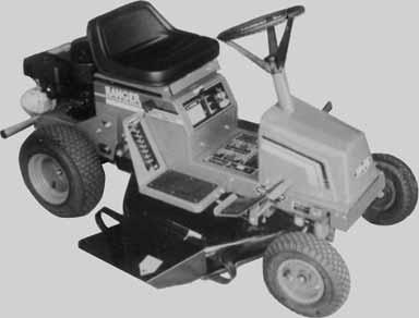

1 Owners Manual RANGER TM AUTO-DRIVE Model No TM


2 SAFETY FEATURES - Traction drive, blade drive and safety - Low centre of gravity, stable wide track interlock - Enclosed drives - Parking brake - Full footrests - Convenient - easy to operate controls AUTOMOTIVE TYPE STEERING WHEEL AUTO BELT TENSIONER ADJUSTABLE MOULDED SEAT REAR MOUNTED ENGINE GEARED STEERING LOW TONE EXHAUST MUFFLER REAR MOUNTED NUDGE BAR RUBBER SEAT BUFFERS BIG 76cm (30 ) CUT CONTOUR FOLLOWING CUTTER HEAD WARNING If fitted with accessories, including any authorised ROVER accessories such as a Grass Catcher, this mower may not comply with AS
3 SPECIFICATIONS ROVER RANGER Model No Engine Make Briggs & Stratton Engine Model No Engine Power 10.5 Hp. Fuel Capacity 2.27 Litres Oil Capacity 1.4 Litres (no filter) Spark Plug Type Champion RC12YC Spark Plug Gap 0.7 to 0.8mm Engine Oil Refer to manufacturers instructions TRANSMISSION Auto-Drive system consists of a continuous belt being driven by the engine pulley over two drive pulleys and around a return pulley. Friction plates are brought into contact with the drive pulleys to impart either forward or reverse motion to the rear drive wheels by means of a drive selector pedal on the right side of the machine. Ground speed at 3600 rpm is variable due to the Auto- Drive system depending on pressure applied to the drive selector pedal. CUTTING HEAD Max. Speed = 8.6km/hr STEERING WHEEL 325 mm Dia. Steering Wheel. 1-1/4turns lock to lock. CLUTCH/ BRAKE PEDAL Foot operated pedal. Left side of machine. PARKING BRAKE KNOB Hand operated catch. Left hand side. Used in conjunction with cluth/brake pedal. DRIVE SELECTOR Foot operated pedal located on right side of the machine. Spring loaded so as to return to neutral position. CUTTING HEIGHT Lever right hand side. 8 height of cut positions from 15mm to 65mm. CUTTER DRIVE Lever located left side of seat cowl. GENERAL Model 160 TYRES Full floating pressed steel housing with right side discharge. Width of cut 760mm (30 ). Wheel Base 1.35m Length 1.64m Track 0.63m R Width 0.80m 0.69m F Turning Circle 5.8m Height 0.95m Turning Radius 2.0m Weight 195kg Front Tyres- Rear Tyres- CONTROLS 4.1 x 6 Tube Pressure 140 Kpa maximum. (20psi) 16 x 6.5 x 8 Tubeless Pressure 96 Kpa maximum. (14psi) * Throttle control with Fast, Slow and Choke positions. * Key switch with OFF, ON and START positions. To emphasise special information the words WARNING and CAUTION are used. WARNING The safety of the user and others involved. Personal injury may result should this information be disregarded. CAUTION Follow these instructions carefully to avoid mower damage and loss of warranty. 2


4 LOOSE PARTS KIT DESCRIPTION QTY USE Steering wheel 1 On steering shaft Roll Pin 1 Secure steering wheel to shaft Stone guard assembly 1 Fitted to cutterhead Spring stone guard 1 On stone guard pivot rod E Clip 1 In groove in pivot rod Ignition keys 2 To start machine Plug spanner 1 Plug removal and fitting Pop Rivets 2 Seat safety switch SETTING UP INSTRUCTIONS Fig. 2 Fig. 4 INSTALLING STEERING WHEEL 1. Slip the steering wheel over the steering shaft and align the wheel hole with the shaft hole. 2. Insert a drift punch partially through the holes to maintain alignment and insert the roll pin in the opposite side. Fig Drive the roll pin in until flush with the outside of the wheel. INSTALLING STONE GUARD 1. Slip the spring into the stone guard pivot rod so that the short leg rests on top of the stone guard. 2. Now twist the spring as shown and feed the end of the pivot rod into the forward pivot bracket. Fig Insert the short end of the pivot rod fully into the rearward pivot bracket. 4. Release the spring. It should spring down onto the top of the cutterhead and be tensioning the stone guard down. 5. Secure by clipping the E Clip into the groove on the pivot rod. Fig. 4. Fig. 3 3


5 INSTALLING THE BATTERY 1. Remove the battery as follows (a) remove the terminal cables from the battery. (b) undo the wingnuts and remove the clamp bar. 2. The battery is not filled with Electrolyte. This should be done by adding 33% strength battery acid to each cell until the plates are covered. Electrolyte must be purchased from a local battery supply outlet. CAUTION Do not overfill battery, acid will overflow into other parts of the machine and severe corrosion and deterioration will result. 3. Leave the filler caps off and connect the battery charger to the battery terminals. Charge the battery at 4 Amps/Hour for a minimum of 6 hours. 4. After charging, check that the Electrolyte is still covering the plates, if not, add to the correct level. Install the filler caps. 5. Replace the battery and secure. 6. Install the positive (red) cable to the positive (+) terminal and the negative (black) cable to the negative (-) battery terminal. Secure for good electrical contact. BEFORE OPERATING FILL CRANK CASE WITH OIL FILL FUEL TANK Refer Safety Instructions. 1. Clean around the fuel tank cap so foreign matter cannot enter the tank when the cap is removed. 2. Using a funnel, fill the tank with unleaded petrol. Replace the cap. 3. Wipe up any petrol that may have spilled. CHECK TYRE PRESSURE Check and maintain tyre pressure at 140 KPA (20PSI) front and 96 KPA (14PSI) rear maximum. ADJUSTING THE SEAT CAUTION Use only unleaded petrol. Do not mix oil with petrol engine damage may result. Tip the seat forward, loosen the seat securing screws. Relocate the seat for operator comfort. Tighten the seat securing screws and lower the seat. Fig 5. The rider mower may be delivered without oil in the crankcase. Oil must be added before attempting to start the engine. 1. Place the machine on level surface. Ensure that the oil plug is securely tightened. Clean around the dipstick. 2. Unscrew and remove the dipstick from the oil filler tube. 3. Insert a funnel into the filler tube and slowly add oil in accordance with the engine manufacturer s direction. 4. Ensure oil level is at the full mark on the dipstick when screwed completely in. When finished, replace the dipstick and re-tighten. Fig. 5 CAUTION Avoid premature engine failure by ensuring the funnel is clean so contaminants are not introduced into the crankcase. Wipe any oil spills so it will not cause dirt to collect on the engine. 4
6 1. THROTTLE CONTROL Mounted on the control panel and connected to the engine carburettor controls. Has the symbols for Slow, Fast and Choke. Fig. 6 CONTROLS IGNITION SWITCH This switch is part of the battery ignition system and has three positions marked for Off, On and Start. The switch is key operated and automatically returns to the On position from the Start position when released. Fig BRAKE/ CLUTCH Foot operated pedal on the left side of machine. Depressing the pedal neutralises the drive belt and engages the Brake Disc. Fig. 7 Fig PARKING BRAKE Hand operated knob left hand side. Depressing the brake/clutch foot pedal enables this knob to be engaged and disengaged. Brake is locked on with knob in up position. Fig DRIVE SELECTION Foot operated right hand side. Depress with toe pressure gives forward motion, depress with heel gives reverse motion. Automatically returns to neutral position when foot is removed. Fig CUTTING HEIGHT ADJUSTER Located on right side of seat. (Fig. 7) with low cut at bottom and high cut at the top setting. Fig CUTTER DRIVE Lever located on left hand side of seat mounting box. Down position disengages blade drive and applies blade brake, up position engages blades. Fig. 7 7 Fig


7 OPERATING INSTRUCTIONS AUTO - DRIVE OPERATION Forward and reverse movement of the mower is controlled by the drive selector pedal. Ground speed of the ride-on mower is controlled by the amount of pressure on the drive selector pedal. Ensure that the mower user is familiar with this means of operation before operating the mower, particularly in tight confined areas. TO START ENGINE NOTE: The engine will not start unless the cutter drive is disengaged, and clutch/brake pedal is depressed and parking brake applied. 1. Depress clutch/brake pedal Apply the parking brake. 2. Move the drive selector to neutral. 3. Disengage the cutter drive. 4. Move the throttle lever to the choke position. 5. Turn the ignition key to the start position and release when the engine starts. 6. Move the throttle lever to about 1/4 position. TO MOW OR DRIVE 1. Depress clutch/brake pedal. 2. Disengage the parking brake. 3. Select height of cut. 4. Move throttle to about 3/4 position. 5. Engage cutter drive. 6. Select desired drive. 7. Slowly release clutch/brake pedal and move off. TO STOP ENGINE 1. Depress clutch/brake pedal. 2. Shift the drive selector to neutral. 3. Disengage the cutter drive. 4. Apply the parking brake. 5. Move throttle lever to the fast position. 6. Turn the ignition key to Off. Remove the keys. ENGAGE CLUTCHES When engaging the cutter drive lever or releasing the clutch/brake pedal, always operate slowly. Do not use a jerking motion. Moving these controls too fast could possibly overload and stall the engine. REMEMBER WARNING The parking brake should always be applied before leaving the machine. The parking brake must be released before attempting to drive. Depress the clutch/brake when starting or coming to a rest. Do not use sudden directional reversal which can cause wheel spinning. 1. Always look behind the machine before reversing. 2. Do not refuel when the engine is running or while the engine is hot. 3. Keep bystanders away Keep hands and feet clear of moving parts. 4. Keep the machine clean of grass and debris. 5. Keep all safety devices (guards and switches) in place and working. TO STOP IN AN EMERGENCY 1. Depress brake/clutch pedal and drive selector pedal together. (This disengages power from the engine and engages the disc brake.) 2. Apply park brake and lock. 3. Move throttle to fast position and switch off ignition key. 4. Dismount from the mower if it is safe to do so. WARNING To avoid loss of control always come to a complete stop before changing drive direction and slow down before turning. CAUTION A check after the first two hours of operation is recommended. Engine failure or rapid engine wear mainly results from the following causes 6. Dirt or abrasives entering the engine via the air cleaner due to (a) The air cleaner element not being serviced regularly, or (b) The air cleaner damaged or dislodged. 6
8 7. Dirt or abrasives entering the engine via the oil filler tube due to- (a) Using a funnel not cleaned of dirt or grit, or, (b) Topping up with contaminated oil stored in an unclean container. 8. Lack of oil. It is important to- (a) Check the oil level regularly (Every 5 hours of operation) (b) Maintain a full sump. Periodically check the machine and the cutting mechanism. If parts are worn or need replacing do so by using only Genuine Rover Replacement parts. Before working on the mower, disconnect the spark plug lead from the spark plug and place it where it cannot contact the spark plug. Check your Rover Ranger frequently for loose nuts, bolts, belts, etc., and keep these items correctly tightened and adjusted. AIR CLEANER Refer to engine manufacturer s manual for detailed instructions. 1. Pull up on air cleaner cover handle and rotate towards engine. 2. Remove air cleaner cover. 3. Carefully lift air cleaner cartridge and pre-cleaner from blower housing. Note: To clean pre-cleaner, wash in soapy water. Squeeze dry in a clean cloth. DO NOT OIL. 4. Tap the air cleaner on a flat surface to dislodge any loose debris. If contaminated, replace. 5. Clean the base of the air cleaner cartridge area carefully to prevent any debris from entering engine. 6. Place the air cleaner pre-cleaner and cartridge into the blower housing. The cartridge must fit securely in base. 7. Align the tabs on the cover with the slots in the blower housing and replace the cover. 8. Hook the handle and close the cover. CAUTION Petroleum solvents, such as kerosene, are not to be used to clean cartridge. They may cause deterioration of the cartridge. DO NOT OIL CARTRIDGE. DO NOT USE PRESSURIZED AIR TO CLEAN OR DRY CARTRIDGE. 7
9 OIL CHANGE Refer engine manufacturers instructions. 1. Place the machine on a level surface. Start and run the engine for a period to warm the oil. MAINTENANCE THROTTLE CONTROL Proper choke operation is dependant on the adjustment of remote controls 1. Loosen the outer cable clamp screw on engine. 2. Set the throttle control to choke position. 3. Adjust the outer cable under clamp plate so that choke is operated. 4. Tighten the clamp plate screw and check (a) Choke does not operate in fast position, (b) Stop switch operates correctly. CARBURETTOR ADJUSTMENT Fig Fit the drain tube to the drain fitting. Fig Place an oil pan under the end of drain tube. 4. Open the drain fitting about 1 turn and allow the oil to drain completely. 5. Retighten the drain fitting and refill the sump with new oil. For correct viscosity and service classification, refer to the engine manufacturers instructions. The carburettor has been factory set and should only require occasional fine tuning. Refer to Engine Manufacturer s Owner s Manual for details adjustment procedures. CAUTION Never tamper with the engine governor setting. Changing of engine governor speed will void engine warranty. SPARK PLUG The spark plug gap gradually increases during engine running and should be checked periodically and whenever the engine malfunctions. 1. Clean around the spark plug area so that dirt will not enter the engine when the spark plug is removed. 2. Disconnect the spark plug lead and remove the spark plug. 3. Check the condition of electrodes and ensure there is no damage to insulator. 4. Carefully clean the spark plug. Do not grit blast. 5. Set the gap between 0.7mm to 0.8mm. 6. Install the spark plug in the engine and tighten. COOLING SYSTEM The Ranger has an air cooled 4 stroke engine. It must be cleared frequently. Remove any build up of grass, dirt or other debris from the 1. Cylinder 2. Cylinder head cooling fins 3. Cooling air intake screen 4. Carburettor governor levers and linkages. This will ensure adequate cooling and correct engine speed. Fig. 11 LUBRICATION GENERAL Using General Purpose Grease (Every 25 hours) Grease nipples on front wheel pivots. Fig. 11 Cam plate bearing area. Fig. 26 Front Axle beam guides. Grease nipples on steering pivot blocks. Fig. 21 Steering gears. Fig. 21 Grease nipples on engagement lever pivot. Steeing pivot blocks. Fig. 23 Using Clean Engine Oil Jockey pivot arms Throttle control cable. Drive Chain. Fig. 23 Cutter drive lever pivot. Clutch/Brake pedal pivot. Fig. 15 Tie rod ball ends. Fig. 11 All connecting rod pivots points. NOTE: All ball bearings are sealed and require no maintenance. 8


 Fig. 12 This will allow front of deck to be lowered to ground. 5. Slide cutterdeck forward.")

10 MAINTENANCE CUTTING UNIT Remove spark plug lead and disengage cutter drive before working on cutter unit, to prevent accidental starting of the engine. Before using the machine always inspect cutting unit to ensure that the cutting disc, blades and blade fittings are not worn or damaged. Always check after striking a solid object. Do not operate machine when unusual vibration occurs. Replace worn or damaged blades in sets to preserve balance. Remove any build-up of grass or clogging within the cutting unit, discharge chute or stone guard. CUTTERHEAD REMOVAL Fig Disconnect push rods & brake rod. Fig Remove the tensioning spring. A loop has been provided on the spring to assist in this operation. Fig Slide cutterback towards back of machine and remove belt from around cutterdeck pulley. 4. Undo large retaining washer bolts (A) Fig. 12 This will allow front of deck to be lowered to ground. 5. Slide cutterdeck forward. This will allow the rear to be lowered to the ground and be slid from under the machine. 6. Replace in reverse order. WHEEL REMOVAL Fig. 13 Fig. 14 WARNING Always deflate tyre before moving rim nuts on front wheel only. Front 1. Chock the rear wheels and remove the front axle nut. Fig Raise the front of the machine. 3. Slide the wheel from the shaft. 4. Replace in reverse order. 5. Re-tighten the axle nut firmly. Rear 1. Chock the front wheels and raise the rear of the machine. 2. Remove the four wheel nuts. 3. Slide the wheel from the hub. Fig Refit the wheel to hub. 5. Replace the wheel nuts and tighten. BRAKE CALIPER ADJUSTMENT NOTE: To remove cutterdeck belt from machine, the belt guard has to be moved away from the drive pulley to allow the belt to be removed from the V-groove and the cutterhead lifting rod is to be disengaged from the cutterhead selection arm assembly to allow belt to be drawn out. 9 Fig Loosen locknut A Fig Adjust Bolt B till brake calliper C touches brake Disc. 3. Re-tighten locknut A. BRAKE ARM ADJUSTMENT 1. Check that brake calliper is correctly adjusted. 2. Adjust locknut E Fig. 15. Till brake arm D Pad comes into contact with disc. 3. Check operation of brake to ensure park brake can be applied, and brake operates correctly.

, two spacers and nyloc nut and remove the Fig. 19 brake plate assembly. 3.")


11 MAINTENANCE PARKING BRAKE Should always be checked for operation after clutch/brake rods have been adjusted. CUTTER DRIVE ADJUSTMENT 1. Move cutter Height Selector Lever to No. 4 Position in Rack. 2. Move cutter Drive Lever to the Engaged position. 3. Adjust Push Rods Fig. 16 to give a spring compression of 35mm. Fig. 17 Fig. 16 CUTTERHEAD BRAKE Should be regularly checked for operation. PAD REPLACEMENT (Refer figure 19) 1. Remove the R Clip (A) from the push rod clevis pin and remove the clevis pin and push rod from brake arm assembly. 2. Remove the brake plate pivot bolt (B), two spacers and nyloc nut and remove the Fig. 19 brake plate assembly. 3. Drill out the two retaining rivets which hold the Brake pad assembly to the brake plate and discard the old brake pad and backing plate. The replacement brake pads are fitted with a chemically bonded backing plate, locate this backing plate against the brake plate and retain with two 3/16 rivets. Part No: A Replace the brake plate to the cutterhead and adjust the cutterhead brake. CUTTERHEAD BRAKE ADJUSTMENT 1. With the cutterhead disengaged and in low cut position. 2. Adjust the nyloc nut on the rod as per step 6 for Cutter Drive Adjustment. 3. Adjust the tension on the spring using the lock nuts to give length of 58mm. Fig. 20 Fig. 20 Fig. 17 STEERING GEARS 4. Adjust Locknut A to give 7mm clearance to back of Swivel Block. Fig Disengage the Cutter Drive Selector Lever. 6. Adjust locknut A in Fig. 20 to give Cutter Engagement Lever a free travel of 30mm, from bottom of slot in Fig. 18 NOTE: Check to ensure lever has 30mm of free travel by working lever. Fig Fig. 21 To adjust the excessive play caused by wear in the gears. 1. Loosen the bolts securing steering shaft pivot block (A) 2. Lightly tap the pivot block towards the layshaft pivot and retighten bolts (A) 3. Check the steering gear engagement. 4. Check that there is no tight spots when turning the steering wheel from lock to lock.
12 MAINTENANCE AUTO-DRIVE The Auto-Drive friction plates and drive pulleys are factory set for travel required along a keyed shaft and this should not need adjusting. If during operation it is found that the relationship between forward and reverse has become unbalanced adjust as follow:- DRIVE SELECTOR PEDAL The pedal angle can be tilted either forward or back to suit individual requirements if necessary. 1. Loosen locknuts (A) on control rod. Fig Tilt control pedal to required angle to give maximum operator comfort. 3. Re-tighten locknuts. 1. Loosen Locknut (A) Fig Centralise engagement lever with the friction plates between the drive pulleys. 3. Re-tighten locknut (A). Fig. 22 Fig. 22 DRIVE CHAIN ADJUSTMENT Primary 1. Loosen off bolt A Fig Slide idler back till chain tightens. 3. Re-tighten bolt A and check chain for tight spots. Secondary 1. Loosen off bolt B Fig Slide sprocket back till chain tightens. 3. Re-tighten bolt B and check chain for tight spots. Fig. 24 CAUTION Do not over-tension belts or drive chains. AUTO BELT TENSIONER The continuous drive belt is kept under constant tension by the Auto-Belt tensioner. This is set up initially at the factory and should not need attention unless the drive belt has stretched past its serviceable use, indicated when the spring finger is engaged in red area on the rack assembly. TO REMOVE OLD BELT 1. Loosen the two nuts (A) securing the spring plate. Fig Remove the top bolt (B) from the spring plate while holding the spring plate and slowly release the tension on the spring and disengage the spring finger from rack assembly by pressing outwards. Fig Remove old belt from around pulleys and discard. SPRING PLATE A SPRING FINGER B Fig. 23 Fig A
 engages in the first couple of teeth on the rack assembly. Fig.")

 on the engine hold down bolts. Fig. 27 9. Loosen locknuts (B) on engine pulley guard and slide to the rear. Fig. 27 10.")
 Fig.")

13 MAINTENANCE TO FIT NEW BELT 4. Ensure that the peg on rack assembly (A) engages in the front slot of cam plate assembly. (B) Fig Fit new drive belt around pulleys. 6. Draw the spring plate back into position and secure. Check that the spring finger (C) engages in the first couple of teeth on the rack assembly. Fig. 26 STEERING RODS Should not normally require resetting. 1. Loosen the rod lock nut (A). Fig Release the fixing bolt. 3. Turn the tie rod end to adjust for length. Clockwise to shorten, anti-clockwise to lengthen. 4. Replace the fixing bolt and tighten. 5. Tighten the rod lock nut. 6. Make sure the rod is free to pivot. CUTTER HEAD TILT Fig. 26 B GREASE If the spring finger engagement in the rack assembly is not at the start of the rack assembly, proceed as follows:- 7. Release the spring plate as per step (2) 8. Loosen the four locknuts (A) on the engine hold down bolts. Fig Loosen locknuts (B) on engine pulley guard and slide to the rear. Fig Adjust nyloc nut (C) on motor adjustment plate to move the engine to the rear and repeat step (6). 11.Re-tighten engine mounting bolts and re-position belt guard with 2-3mm clearance between belt guard and engine pulley. This will not normally require resetting. 1. Loosen the U-Bracket nuts (B) Fig Adjust the nuts up or down to set tilt. 3. Model 160 (760mm cut) requires the back of the blade circle tilted 15mm above the front of the blade circle in low cut position. 4. Re-tighten all nuts. STEERING STOPS These will not normally require resetting. 1. Check if the steering segment gear rotates in both directions. 2. Loosen the locknut on the front beam and adjust the bolt till number of turns in both directions is equal. 3. Re-tighten the Locknut. HEIGHT OF CUT ADJUSTMENT To adjust the height of cut rotate the nyloc nut (A) situated under the centre of machine on the rear cutterhead support assembly. Adjust the nyloc nut to obtain low cut at front of blade circle of 15mm. Fig. 28 A Fig. 27 NOTE: After a period of time the drive belt will stretch past the limit of the auto-tensioner. The autotensioner can be reset to allow for this stretching by following the above instructions- steps (7) to (11). Re-grease the bearing area under cam plate when fitting new belt. Fig Fig. 28 SAFETY INTERLOCK SYSTEM The safety interlock system has been designed for your protection and should not be tampered with. It gives the Ranger the following characteristics.
14 MAINTENANCE The engine will not start unless the clutch/brake pedal is depressed and the cutter drive is disengaged. WARNING The engine will stop if the operator leaves the seat with the speed selector engaged and/ or the cutter drive engaged. WARNING If the interlock system fails, see an authorised Rover Service Dealer. Do not operate the mower until the fault is corrected. CAUTION The safety switch circuit may become defective if wet. Do not spray switches and connections. SAFETY SWITCH ADJUSTMENTS Clutch Brake Pedal 1. Depress the clutch brake pedal and apply the parking brake. 2. Loosen the two safety switch retaining screws and slide the safety switch towards the rear of the mower. Fig Depress the clutch brake pedal and release the parking brake allowing the clutch brake pedal to return to its normal disengaged position. 4. Slide the safety switch towards the tab on the clutch brake shaft. Position the safety switch with a clearance of 6mm between the safety switch body and the tab. 5. Tighten the two safety switch retaining screws. STORAGE: Never store the engine with fuel in tank indoors or in poor ventilated enclosures where the fuel fumes may accumulate. If the machine is to be stored over 30 days proceed as follows: 1. Remove all fuel from the carburettor and the fuel tank to prevent varnish-like gum deposits. 2. Remove the spark plug and pour 30ml of engine oil into the cylinder. Crank the engine several times to distribute the oil. Replace the spark plug. 3. Clean the engine and cooling fins, etc., and any clippings, dirt and chaff. 4. Clean the underside of the mower and cutting unit. Paint any chips or scratches. 5. Lubricate the chassis components. 6. Remove and charge the battery and store in a cool dry spot. Recharge every 30 days. 7. Store the machine in a clean dry place. REMOVAL FROM STORAGE 1. Change the oil 2. Fill the fuel tank with fuel 3. Check the spark plug 4. Check the drive belts 5. Check the drive chain 6. Lubricate the drive chain 7. Lubricate the pivot points 8. Grease the front axle spindles 9. Check the tyre pressure 10.Check safety interlock 11.Check cutting blades. 13 Fig. 29 Clutch brake safe switch Cutter Engagement Safety Switch The cutter engagement safety switch does not require any routine adjustment. It should be checked occasionally for operation, working condition and it s fasteners checked for tightness. Seat Panel Safety Switch 1. Raise the seat panel and allow it to open till it rests on the steering wheel. 2. Loosen the two safety switch retaining screws. 3. Position the safety switch to give the safety switch button 10mm of protrusion above the cowl body panel. 4. Tighten the two safety switch retaining screws.
15 WARNING Before undertaking any maintenance, cleaning or adjustments, apply the parking brake and remove the ignition key. 14
16 TROUBLE SHOOTING PROBLEM POSSIBLE CAUSES CORRECTIVE ACTION Engine loses power. 1. Oil level in crank case is low. 1. Add oil to crankcase. 2. Cooling fins and air passages 2. Remove obstruction from under engine blower housing are passages. blocked. 3. Engine load is excessive. 3. Select a lower speed to reduce load. 4. Air cleaner is dirty. 4. Clean air cleaner element. 5. Dirt or water is in fuel system. 5. Have machine serviced by Authorised Service Dealer. 6. Carburettor is adjusted incorrectly. 6. Adjust the carburettor. 7. Spark plug is pitted, fouled or 7. Install new correctly gapped defective in some other way. Spark plug. Engine over heats. 1. Cooling fins and air passages 1. Remove obstruction from under engine blower housing are cooling fins and air passages. Blocked. 2. Carburettor is adjusted incorrectly. 2. Adjust the carburettor. 3. Oil level in crankcase is low. 3. Add oil to crankcase. 4. Engine load is excessive. 4. Select a lower speed to reduce load. Mower vibrates abnormally 1. Engine mounting bolts are loose. 1. Tighten mounting bolts. 2. Loose cutter pulley, idler pulley or 2. Tighten the appropriate pulley. drive pulley. 3. Cutter assembly is unbalanced. 3. Replace broken blades in sets. 4. Cutter assembly is loose. 4. Tighten securing nut. Cutter does not rotate. 1. Cutter drive belt is worn, loose or 1. Install new cutter drive belt. broken 2. Cutter drive belt is off pulley. 2. Install cutter drive belt. Mower does not drive 1. Drive belt is worn, loose or Install new drive belt. broken 2. Drive belt is off pulley. 2. Install drive belt. 3. Unable to select forward 3. Have machine serviced by or reverse. Authorised Service Dealer. \ Engine does not start, hard 1. Fuel tank is empty. 1. Full fuel tank with petrol. to start, loses power, or fails to 2. Speed selected. 2. Select Neutral. keep running. 3. Cutter Drive is engaged. 3. Disengage Cutter Drive. 4. Spark plug is loose. 4. Tighten spark plug. 5. Spark plug lead is loose or 5. Install spark plug lead on disconnected from spark plug. spark plug. 6. Spark plug gap is incorrect. 6. Set spark gap between electrodes at 0.7mm to 0.8mm 7. Spark plug is pitted, fouled or 7. Install new correctly gapped defective in some other way. spark plug. 8. Wrong spark plug is used. 8. Install correct spark plug. 9. Electrical connections are loose. 9. Check electrical system to ensure good contact. 10. Carburettor is adjusted incorrectly. 10. Adjust the carburettor. 11. Air cleaner is dirty. 11. Clean the air cleaner element. 12. Vent hole in fuel tank is plugged. 12. Inspect and open vent. } 13. Dirt or water in fuel system 14. Dead battery. 15. Defective Electronic Ignition 13. Have machine serviced by System. Authorised Service Dealer. 16. Defective Safety Switches. Engine does not idle or idles poorly. 1. Air cleaner is dirty. 1. Clean air cleaner element. 2. Oil level in crankcase is low. 2. Add oil to crankcase. 3. Cooling fins and air passages 3. Remove obstruction from cooling under engine blower housing are fins and air passages. plugged. 4. Idle speed is too low or high. 4. Adjust the carburettor. 5. Dirt or water is in fuel system. 5. Have machine serviced by Authorised Service Dealer. 6. Vent hole in fuel tank is plugged. 6. Clean fuel tank vent. 7. Spark plug is pitted fouled or 7. Install new correctly gapped spark defective in some other way. plug. 15
17 SAFETY AND INSTRUCTION DECALS Safety and Instruction decals that are mounted on the RANGER Rear Engine Ride On Mower. Replace any that become damaged or illegible. P/N A
18 CIRCUIT DIAGRAM AND SPARES 17
19 SAFETY INSTRUCTIONS This product is manufactured to comply with Australian Safety Standards. If nongenuine replacement parts; including blades; are fitted to this product it may no longer meet that Australian Safety Standard and Rover Mowers Warranty. The fitting of non-genuine replacement parts could result in serious injury, and, or machine malfunctioning which may result in litigation against the person or persons responsible for the alterations. * Know your controls. Read the owner s manual carefully. Learn how to stop the engine quickly in an emergency. * Do not allow children or people unfamiliar with these instructions to use the mower. Do not carry passengers. * Make sure the lawn is clear of sticks, stones, bones, wire and debris. They could be thrown by the blade. * Do not mow whilst people, especially children, or pets are in the mowing area. * Never mow across the face of the slope, unless the mower is designed for this purpose. * Exercise extreme caution when on slopes. Reduce speed on slopes and in sharp turns to prevent overturning or loss of control. Do not stop or start suddenly when going uphill or downhill. * Stay Alert for holes in the terrain and other hidden hazards. Use care when pulling loads or using heavy equipment (a) use only approved drawbar hitch points (b) limit loads to those you can safely control (c) do not turn sharply (d) use care when backing up, and (e) use counterweight(s) or wheel weights when suggested in the owner s manual. * Watch out for traffic when crossing or operating the mower near roadways * Stop the blades rotating before crossing surfaces other than grass. * When using any attachments, never direct discharge of material toward bystanders nor allow anyone near the machine while it is in operation. * Before leaving the operator s position (a) disengage all clutches and secure cutting units (b) change into neutral and set the parking brake, and (c) stop the engine and remove the key. * Stop the engine and disengage drive to attachments (a) before refuelling (b) (c) (d) (e) (f) (g) before removing grass-catcher/ catchers before making height adjustment unless adjustment can be made from the operator s position before clearing blockages before checking, cleaning or working on the mower after striking a foreign object (inspect the mower for damage and make repairs before restarting and operating the equipment) and if machine starts to vibrate abnormally (check immediately) * Disengage drive to attachments when transporting or not in use. * A mower operator should be in good physical and mental health and not under the influence of any drug or alcohol which might impair vision, co-ordination or judgement. * Never mow while barefoot or wearing open sandals, or thongs. Wear long trousers and heavy shoes. * It is advisable to wear suitable eye protection when operating a mower. * Mow only in good daylight. * Before using, always visually inspect to see that blades, blade bolts and cutter assembly are not worn or damaged. Replace worn or damaged blades and bolts in sets to preserve balance. DAMAGED BLADES AND WORN BOLTS ARE MAJOR HAZARDS * Check all nuts, bolts and screws often, always be sure the mower is in safe operating condition. * Keep safety devices (guards and switches) in place and in working order. * Never use the mower unless the grass catcher, or guards provided by the manufacturer, are in position. * Ensure any spare parts used comply with the original manufacturer s recommendations and specifications. * Replace worn or faulty silencers. * Keep engine free of grass, leaves or excessive grease. These can be a fire hazard. * Refuel outdoors only. Do not smoke while fueling the engine. Never remove the cap of the fuel tank or add petrol while the engine is running or the engine is hot. Remove fuel cap slowly to relieve any tank pressure. If petrol is spilled, do not attempt to start the engine but move machine away from the area of the spill and avoid creating any source of ignition until petrol vapours have dissipated. * Check for fuel leaks while refuelling or using the mower. If a fuel leak is found, do not start or run the engine until the fuel leak is fixed and spilled fuel is wiped away. * Do not operate the engine in a confined space where exhaust fumes (carbon monoxide) can collect. * Always mount the mower on the opposite side of the discharge chute. * Start the engine carefully with the cutting means disengaged. * Do not over-speed the engine or alter governor settings. Excessive speed is dangerous and shortens mower life. * Stop the engine whenever you leave the mower, even for a moment. * Store the mower in a well-ventilated room away from naked flames such as may be found in hot water heaters. * Do not lend or sell the mower without the Owner s Manual. WARNING If fitted with accessories, including any authorised Rover accessories such as Grass Catcher, this mower may not comply with AS
20 Warranty Conditions Rover Mowers Limited warrant that this machine is free from defects in material and workmanship. This warranty is limited to making good or replacing any part which appears upon inspection by the manufacturer or his agent to be defective in material or workmanship. The engine used to power this machine is warranted by the manufacturer whose warranty statement has been included with the machine. As the warranty for the engine may differ from the warranty for the other components, you are advised to read the engine manufacturer s warranty carefully For other items this warranty shall apply for a period of 12 months from the date of purchase except for products used commercially where the warranty is limited to 90 days. This warranty does not obligate the manufacturer, his agents or dealers to bear the transport costs incurred in the repair or replacement of any defective part. This warranty excludes fair wear and tear, or any damage caused by misuse or abuse. Parts such as blades, blade bolts, v- belts and spark plugs, which can be subjected to use beyond their normal intended working capacity are also excluded. AUSTRALIA &NEW ZEALAND ONLY Online warranty registration - For your record: This warranty is void if parts other than genuine have been used or if repairs or alterations have been made without the manufacturer s written authority. The above warranty does not exclude any condition or warranty implied by the Trade Practices Act 1974 or any other relevant legislation which implies any condition which cannot be excluded. EXTENDED WARRANTY: For domestic use only, a 24 month extended warranty applies. It requires the customer to complete the 2 year warranty registration card, and forward along with a copy of the cash register receipt to Warranty, Rover Mowers Limited, Normal warranty exclusions as listed still apply. REMEMBER: PROOFOFPURCHASE IS THE RESPONSIBILITYOFTHE OWNER AND IS NECESSARY PRIOR TO WARRANTY WORK BEING UNDERTAKEN. REPAIRS MUST BE CARRIED OUT BY AN AUTHORISED ROVER DEALER /SERVICE AGENT AND GENUINE SPARE PARTS MUST BE USED OR YOUR WARRANTY WILL BE VOID. Dealer s Name:... Dealer s Address:... Dealer s Phone No:... Product Model No:... Product Serial No:... Date of Purchase:... Rover Mowers Limited reserves the right to make changes of and add improvements upon its product at any time without notice or obligation. The Company also reserves the right to discontinue manufacture of any product at its discretion at any time. ISO 9001 Lic Standards Australia A.B.N Rover Mowers Australia PO Box 1235 Eagle Farm. Qld 4009 Australia. RECYCLED PAPER This Rover Owners Manual has been printed on 100% Australian recycled paper as a sign of Rover Mowers commitment to Greening Australia and New Zealand. Rover Mowers New Zealand East Tamaki, Auckland. New Zealand. GWAIL GROUP PRINTED IN AUSTRALIA Rev. G Copyright 8/2005
Owners Manual MODEL 45 REEL MOWER MODELS & 45148
 Owners Manual MODEL 45 REEL MOWER TM MODELS 45048 & 45148 TM Rover Mowers Limited Model 45 FOREWORD Thank you for buying a Rover Mower. This manual covers the operation and maintenance of the Rover Model
PROOF OF PURCHASE IS THE RESPON-
 Owners Manual TM SAFETY INSTRUCTIONS A mower user must be in good physical condition and mental health and not under the influence of any drug or alcohol which might impair vision, co-ordination or judgement.
Owners Manual. Instructions & Original Parts Listings. Model GT04350 I.P.D Slasher
 Owners Manual Instructions & Original Parts Listings Model GT04350 I.P.D Slasher Greenfield Mowers Pty Ltd 123 Boundary Rd, Rocklea. QLD 4106 Ph: (07) 3875 9400 F: (07) 3875 9425 E: info@greenfield.com.au
M. E. Y. EQUIPMENT MOWER MANUAL
 M. E. Y. EQUIPMENT MOWER MANUAL 200 COLLIER ROAD, BAYSWATER. WESTERN AUSTRALIA 6053 TELEPHONE (08) 9370 1110, FACSIMILE (08) 9370 2566 Web Site: www.mey.com.au Email: info@mey.com.au INTRODUCTION The technical
SAFETY INSTRUCTIONS! BEFORE STARTING
 OWNER S MANUAL H660 SAFETY INSTRUCTIONS! BEFORE STARTING: Know your controls. Read the owners manuals thoroughly. Learn how to stop the engine quickly in an emergency. Inspect the area to be mown, remove
Operating and Assembly Manual
 Model 1080 Operating and Assembly Manual Midwest Equipment Manufacturing, Inc. 5225 Serum Plant Road Thorntown, IN 46071 08-02-16 SAFETY RULES Remember, any power equipment can cause injury if operated
Operating Instructions
 Please Read These Instructions Before Using Your Mower Operating Instructions for model HP470 & SP470 Lawnmowers with Briggs & Stratton engine Product Codes: 99646/BQ 97646/BQ Call our Helpline if you
44 and 52 Twin Bagger 100 Series Z Master
 Form No. 7 87 and 5 Twin Bagger 00 Series Z Master Model No. 7855 Serial No. 000000 and Up Operator s Manual English (CE) Contents Page Introduction................................ Safety.....................................
Wheel Horse. 42 Mower. for Lawn and Garden Tractors. Model No & Up. Operator s Manual
 FORM NO. 9 559 Rev A Wheel Horse 4 Mower for Lawn and Garden Tractors Model No. 78 890000 & Up Operator s Manual IMPORTANT: Read this manual carefully. It contains information about your safety and the
Model 858-RH. Operating and Assembly Manual. Palmor Products Inc Serum Plant Road Thorntown, IN 46071
 Model 5-RH Operating and Assembly Manual Palmor Products Inc. 55 Serum Plant Road Thorntown, IN 6071 3/31/015 SAFETY RULES Remember, any power equipment can cause injury if operated improperly or if the
STIGA TORNADO 51 S 51 SE PRO 51 S
 STIGA TORNADO 51 S 51 SE PRO 51 S 8211-0225-09 SVENSKA S 1 2 3 1. 2. ADD FULL FULL ADD ADD FULL 0,15 l. 3. LS 45 4. XTE 60 3x 5. LS 45 6. XTE 60 STOP I H 7. 8. 2 S SVENSKA 9. 10. 11. 12. LS 45 0,75 mm
DEUTSCHER HE660 OWNER S INSTRUCTION MANUAL AND PARTS LIST
 www.deutschermowers.com.au DEUTSCHER HE660 OWNER S INSTRUCTION MANUAL AND PARTS LIST INDEX 3-4... Assembly Instructions 5-6... Safety Instructions 7... Routine Care and Storage 7... Specifications 8-9...
Operating and Assembly Manual
 Model 470-/H/PRO/IC Operating and Assembly Manual Midwest Equipment Manufacturing, Inc. 5225 Serum Plant Road Thorntown, IN 46071 11-11-11 SAFETY RULES Remember, any power equipment can cause injury if
GROUNDSMASTER. 52 Recycler. for 120 Traction Unit. Model No & UP. Operator s Manual
 FORM NO. 8-980 Rev A GROUNDSMASTER 5 Recycler for 0 Traction Unit Model No. 077 79000 & UP Operator s Manual IMPORTANT: Read this manual carefully. It contains information about your safety and the safety
Operating Instructions
 Please Read These Instructions Before Using Your Mower Operating Instructions for SP470 ES Lawnmower with Briggs & Stratton engine Product Code: 99468/BQ Call our Helpline if you have any problems: Helpline
Table of Contents. Safety symbols... 3 Assembly 6. Operation Maintenance Troubleshooting 11. Storage. 12. Notes. 13
 Table of Contents Safety symbols... 3 Assembly 6 Operation... 8 Maintenance... 10 Troubleshooting 11 Storage. 12 Notes. 13 2 Safety Information Attention; this machine can be dangerous! All operators should
Parklander Cylinder Mower
 Parklander Cylinder Mower WARNING: To reduce the risk of injury, the user must read and understand the Operator s Manual before using this product. Save these instructions for future reference. Table of
36 Rear Discharge Mower
 FORM NO. 8 95 Rev. A Wheel Horse 6 Rear Discharge Mower for Classic Garden Tractor Model No. 7805 790000 & Up Operator s Manual IMPORTANT: Read this manual carefully. It contains information about your
Model 452-DIC/DH. Operating and Assembly Manual
 . Model 452-DIC/DH Operating and Assembly Manual Palmor Products Inc. 5225 Serum Plant Road Thorntown, IN 46071 02-14-12 SAFETY RULES Remember, any power equipment can cause injury if operated improperly
5.5KVA GENERATOR MODEL NO: PG6500DVES OPERATION & MAINTENANCE INSTRUCTIONS PART NO: LS0616
 5.5KVA GENERATOR MODEL NO: PG6500DVES PART NO: 8857810 OPERATION & MAINTENANCE INSTRUCTIONS LS0616 INTRODUCTION Thank you for purchasing this CLARKE 5.5KVA Generator. Before attempting to use this product,
3KVA DUAL VOLTAGE GENERATOR MODEL NO: PG3800DV
 3KVA DUAL VOLTAGE GENERATOR MODEL NO: PG3800DV PART NO: 8857815 OPERATION & MAINTENANCE INSTRUCTIONS LS1016 INTRODUCTION Thank you for purchasing this CLARKE 3KVA Dual Voltage Generator. Before attempting
North Dakota State University Grounds Maintenance Equipment
 North Dakota State University Grounds Maintenance Equipment I. Introduction Grounds maintenance equipment is an important part of the work activities on NDSU campus. They can make grounds maintenance jobs
ProLine. 44 Mower. for 120 Traction Unit. Model No & Up. Operator s Manual
 FORM NO. 9 ProLine Mower for 0 Traction Unit Model No. 05 99000 & Up Operator s Manual IMPORTANT: Read this manual carefully. It contains information about your safety and the safety of others. Also become
42in GT Classic Single Stage Snowthrower Conversion Kit XT Series Garden Tractor
 Form No. 9 66 in GT Classic Single Stage Snowthrower Conversion Kit XT Series Garden Tractor Part No. 06 88 Installation Instructions English (EN) This kit is for installing an existing 00 Series Classic
52 inch Twin Bagger and Finishing Kit 200 Series Z Master
 Form No. 9 68 inch Twin Bagger and Finishing Kit 00 Series Z Master Model No. 7898 Serial No. 000000 and Up Model No. 780 Operator s Manual English (EN) Contents Page Introduction................................
WHEEL HORSE LAWN TRACTOR
 FORM NO. 897 WHEEL HORSE LAWN TRACTOR FOR AND 8 MOWERS SET-UP INSTRUCTIONS Loose Parts Note: Use the chart below to verify all parts have been shipped. DESCRIPTION QTY. USE Front Wheel Shim Washer (as
Operating and Assembly Manual
 Model 455-IC/PRO/H Operating and Assembly Manual Midwest Equipment Manufacturing, Inc. 5225 Serum Plant Road Thorntown, IN 46071 03-08-12 SAFETY RULES Remember, any power equipment can cause injury if
Operating and Assembly Manual
 Model 455-IC/PRO/H Operating and Assembly Manual Palmor Products Inc. 5225 Serum Plant Road Thorntown, IN 46071 03-08-12 SAFETY RULES Remember, any power equipment can cause injury if operated improperly
48 Side Discharge Mower
 FORM NO. 9 650 Rev A Wheel Horse 8 Side Discharge Mower for Classic Garden Tractor Model No. 786 890000 & Up Operator s Manual IMPORTANT: Read this manual carefully. It contains information about your
TO THE OWNER ASSEMBLY
 TO THE OWNER This is an operational and general maintenance manual only and does not cover repair. All repair work must be performed by an authorized BOLENS DEALER or the factory warranty is void. Bolens
LAWN MOWER OWNER S MANUAL
 LAWN MOWER OWNER S MANUAL Woodies SKU: 1153279 & 1153280 CAUTION: Read and follow all Safety Rules and Instructions before operating this equipment Thank you for choosing our Gasoline Lawnmower. 1 To ensure
Wheel Horse. 48 Mower. for Lawn and Garden Tractors. Model No & Up. Operator s Manual
 FORM NO. 5 Wheel Horse 48 Mower for Lawn and Garden Tractors Model No. 786 990000 & Up Operator s Manual IMPORTANT: Read this manual carefully. It contains information about your safety and the safety
42in GT Classic Single Stage Snowthrower Conversion Kit XT Series Garden Tractor
 Form No. 5 70 in GT Classic Single Stage Snowthrower Conversion Kit XT Series Garden Tractor Part No. 06 858 Installation Instructions Original Instructions (EN) This kit is for installing an existing
Wheel Horse. 52 Mowers. Model No & Up Model No & Up. Operator s Manual
 FORM NO. 9-567 Wheel Horse 5 Mowers for Lawn & Garden Tractors Model No. 7880 890000 & Up Model No. 7885 890000 & Up Operator s Manual IMPORTANT: Read this manual carefully. It contains information about
Operating and Assembly Manual
 Model 380/385-IC/385-LH Operating and Assembly Manual Midwest Equipment Manufacturing, Inc. 5225 Serum Plant Road Thorntown, IN 46071 2-0916 SAFETY RULES Remember, any power equipment can cause injury
DFS Vac Collection System 400 Series Z Master
 Form No. 0 DFS Vac Collection System 00 Series Z Master Model No. 780 Serial No. 000000 and Up Operator s Manual Register your product at www.toro.com Original Instructions (EN/GB) Contents Page Introduction................................
LAWN MOWER OWNER S MANUAL
 LAWN MOWER OWNER S MANUAL 1.8kW Petrol Engine 123CC 420mm CUTTING WIDTH MODEL: S421-C SAFETY OPERATION ASSEMBLY MAINTENANCE WARRANTY CAUTION: Read and follow all Safety Rules and Instructions before operating
48 Side Discharge Mower
 FORM NO. 9 7GB Wheel Horse 48 Side Discharge Mower for Lawn & Garden Tractors Model No. 7868 790000 & Up Operator s Manual IMPORTANT: Read this manual carefully. It contains information about your safety
MODEL 565CKG Operating and Assembly Manual Midwest Equipment Manufacturing, Inc Serum Plant Road Thorntown, IN 46071
 MODEL 565CKG Operating and Assembly Manual Midwest Equipment Manufacturing, Inc. 5225 Serum Plant Road Thorntown, IN 46071 11-20-14 SAFETY RULES Remember, any power equipment can cause injury if operated
36 Tiller Wheel Horse Lawn and Garden Tractor Attachment
 Form No. 9 6 Rev B 6 Tiller Wheel Horse Lawn and Garden Tractor Attachment Model No. 797 890000 and Up Operator s Manual English(En) Contents Page Introduction................................ Safety.....................................
LAWNMOWER OWNER S MANUAL & Service Record Booklet HUT216
 LAWNMOWER OWNER S MANUAL & Service Record Booklet HUT216 Contents WARRANTY 2 SAFETY INSTRUCTIONS 3 COMPONENT IDENTIFICATION 5 SETUP INSTRUCTIONS 6 IMPORTANT: BEFORE YOU START THE MOWER 7 OPERATIONAL PROCEDURES
Wheel Horse. 44 Snowthrower. for 5xi Lawn and Garden Tractors. Model No & Up. Operator s Manual
 FORM NO. 8 Rev A Wheel Horse Snowthrower for 5xi Lawn and Garden Tractors Model No. 7966 890050 & Up Operator s Manual IMPORTANT: Read this manual, and your tractor manual, carefully. They contain information
Finishing Mower Estate 72
 Finishing Mower Estate 72 Owners/Operators Manual & Spare Parts List Issue Date: October 2011 1 Introduction Your FIELDMASTER Estate 72 Finishing Mower has been designed to do a range of work to your satisfaction.
PETROL LAWNMOWER OPERATING INSTRUCTIONS MODELS: LSM 4540 L M
 PETROL LAWNMOWER OPERATING INSTRUCTIONS MODELS: LSM 4540 L M-851-40 Thank you for purchasing the Lawn Star Lawnmower which is one of the finest and most advanced lawnmowers today s technology can produce.
Owners Manual. Instructions & OE Parts Listings. Model GT22875SD 25/32 Steel Deck Model GT /34 Deluxe
 Owners Manual Instructions & OE Parts Listings Model GT2270 17.5/32 Standard Model GT2290 17.5/32 Steel Deck Model GT22875 25/32 Standard Model GT22875SD 25/32 Steel Deck Model GT22895 17.5/34 Deluxe Model
135CC PETROL LAWN MOWER INSTRUCTION MANUAL DYM-1773
 135CC PETROL LAWN MOWER INSTRUCTION MANUAL DYM-1773 CONTENTS Warranty 2 Introduction 3 Environmental protection 3 Description of symbols 3 Specifications 4 Safety rules for petrol lawn mowers 4 Operation
1P88F-1 1P90F-1 1P92F-1. Owner's Manuel
 1P88F-1 1P90F-1 1P92F-1 Owner's Manuel EN 1 TABLE OF CONTENTS 1. General information... 1 2. Safety regulations... 1 3. Components and controls... 2 4. What you need to know... 3 5. Standards of use...
1200W INVERTER GENERATOR
 1200W INVERTER GENERATOR MODEL NO: IG1200 PART NO: 8877070 OPERATION & MAINTENANCE INSTRUCTIONS LS0117 INTRODUCTION Thank you for purchasing this CLARKE 1200W Inverter Generator. Before attempting to use
Safety Instructions, Installation & Operator s Manual For
 Safety Instructions, Installation & Operator s Manual For #6-3173 TWIN BAG GRASS CATCHER KIT FOR 38 YARD CRUISERS SERIES 2 MODEL YZ145382BVE IMPORTANT! THIS KIT NOT INTENDED FOR USE ON ANY SERIES OF HZ/HZS
GENERATOR MODEL NO: FG2500 OPERATION & MAINTENANCE INSTRUCTIONS PART NO: LS0114
 GENERATOR MODEL NO: FG2500 PART NO: 8857727 OPERATION & MAINTENANCE INSTRUCTIONS LS0114 INTRODUCTION Thank you for purchasing this CLARKE Generator. Before attempting to use this product, please read this
Trench Filler for Compact Utility Loaders
 Form No. 3353-608 Rev A Trench Filler for Compact Utility Loaders Model No. 22472 260000001 and Up Operator s Manual Register your product at www.toro.com Original Instructions (EN) Contents Page Introduction................................
Worldlawn Power Equipment, Inc. Industrial Park 2415 Ashland Ave. Beatrice, NE Toll Free Number:
 Operator s Manual R WYZ48/52/60CS BAGGER Worldlawn Power Equipment, Inc. Industrial Park 2415 Ashland Ave. Beatrice, NE 68310 Toll Free Number: 1-800-267-4255 OPERATOR S MANUAL This catcher manual is for
Z Master. 62 Mower. for Z Master Z 255 Traction Unit. Model No & UP. Operator s Manual
 FORM NO. 9 88 Z Master 6 Mower for Z Master Z 55 Traction Unit Model No. 7408 89000 & UP Operator s Manual IMPORTANT: Read this manual carefully. It contains information about your safety and the safety
Reproduction. Not for OPERATOR S MANUAL. Turbo Vacuum System. Model Description Turbo Vacuum Collection System (For 60 Mower Decks)
") OPERATOR S MANUAL Turbo Vacuum System Model Description 1695759 Turbo Vacuum Collection System (For 60 Mower Decks) Copyright Briggs & Stratton Power Products Group, LLC Milwaukee, WI USA. All Rights Reserved.
OPERATOR S MANUAL Turbo Vacuum System Model Description 1695759 Turbo Vacuum Collection System (For 60 Mower Decks) Copyright Briggs & Stratton Power Products Group, LLC Milwaukee, WI USA. All Rights Reserved.
Operating and Assembly Manual
 Model 462-ZIC/ZH/ZPRO Operating and Assembly Manual Midwest Equipment Manufacturing, Inc. 5225 Serum Plant Road Thorntown, IN 46071 12-14-16 SAFETY RULES Remember, any power equipment can cause injury
Operator's Manual. VC-60 & VC-60 Plus Harper Industries, Inc. 7/03 Part No
 Operator's Manual VC-60 & VC-60 Plus 2003 Harper Industries, Inc. 7/03 Part No. 970066 Thank you for purchasing a Harper/Goossen Verti-Cutter. As with all Harper/Goossen products, the Harper/Goossen Verti-Cutter
WARNING: Read these instructions before using the machine GENERATOR MODEL NO: IG3500F PART NO: OPERATION & MAINTENANCE INSTRUCTIONS
 WARNING: Read these instructions before using the machine GENERATOR MODEL NO: IG3500F PART NO: 8877100 OPERATION & MAINTENANCE INSTRUCTIONS ORIGINAL INSTRUCTIONS LS0217 INTRODUCTION Thank you for purchasing
Model 560 Model 580. Operating and Assembly Manual. Midwest Equipment Mfg Serum Plant Road Thorntown, IN 46071
 Model 560 Model 580 Operating and Assembly Manual Midwest Equipment Mfg. 5225 Serum Plant Road Thorntown, IN 46071 10/14/2018 SAFETY RULES Remember, any power equipment can cause injury if operated improperly
1100W PORTABLE GENERATOR
 1100W PORTABLE GENERATOR MODEL NO: G1200 PART NO: 8010110 OPERATION & MAINTENANCE INSTRUCTIONS LS0312 INTRODUCTION Thank you for purchasing this CLARKE 1100W Portable Generator. Before attempting to use
USER MANUAL Rotary Lawn Mower
 USER MANUAL Rotary Lawn Mower SAFETY OPERATION MAINTENANCE Your lawn mower has been engineered and manufactured to our high standard for dependability, ease of operation, and operator safety. WARNING:
Operating Instructions
 Please Read These Instructions Before Using Your Mower Operating Instructions for model HL454HP & HL454SP Lawnmowers powered by Mountfield V35 engine Product Codes: 299164643/BQ 299264643/BQ These instructions
42 Mower Wheel Horse Classic Garden Tractor Attachment
 Form No. 6 9 Mower Wheel Horse Classic Garden Tractor Attachment Model No. 78 000000 and Up Operator s Manual Domestic English (EN) Contents Page Introduction................................ Slope Chart..............................
48 Mower Wheel Horse Classic Garden Tractor Attachment
 Form No. 6 96 Rev B 8 Mower Wheel Horse Classic Garden Tractor Attachment Model No. 786 000000 and Up Operator s Manual Domestic English (EN) Contents Page Introduction.................................
KING COBRA/CALIBER GRASS COLLECTION SYSTEM PARTS & OPERATORS MANUAL
 KING COBRA/CALIBER GRASS COLLECTION SYSTEM PARTS & OPERATORS MANUAL GRASS CATCHER W/WEIGHTS: TUBE KITS: BLOWER KITS: 52 542128 52 542119 5101002 60 542129 60 542120 5101003 2 WORLDLAWN POWER EQUIPMENT
Precision Reel Mowers OPERATOR S MANUAL
 Precision Reel Mowers OPERATOR S MANUAL Models RL205 / RL207 RL255 / RL257 / RL2510 Introduction Read this information carefully to learn how to operate and maintain your product properly and to avoid
Side Discharge Chute Oil Filler & Dipstick Silencer/Exhaust
 1 SPECIFICATION Electric Start Engine - Size 6HP Engine speed 2850rpm Metal Deck Cutting width 550mm (22 ) Adjustable cutting height 7 Grass collection capacity 60L Gross weight 41Kg Fuel type Unleaded
BrentChalmers.com. Owner Operation and Maintenance Manual ROTARY MOWER MODEL WISCONSIN,U.S.A. PORT ATTACHMENT 28 INCH WASHI~GTON,
 ROTARY MOWER Owner Operation and Maintenance Manual ATTACHMENT 28 INCH MODEL 15100-01 (2) Do not allow children to operate powered equipment at any time. The average child is not capable of coping with
LC 18 LC 19 LC 19A LC 19AP
 Operator s manual LC 18 LC 19 LC 19A LC 19AP Please read the operator s manual carefully and make sure you understand the instructions before using the machine. English KEY TO SYMBOLS Key to symbols WARNING
Classic Petrol - Seite 3 Seite 1 Montag, 23. Februar :37 15 STOP
 Classic Petrol - Seite 3 Seite 1 Montag, 23. Februar 2004 3:37 15 STOP 1 2 3 4 5 6 7 8 9 10 Classic Petrol - GB Seite 2 Mittwoch, 25. Februar 2004 8:18 08 Product Specification Cylinder Mower Qualcast
Operating and Assembly Manual
 Model CV385-PRO Operating and Assembly Manual Midwest Equipment Manufacturing, Inc. 5225 Serum Plant Road Thorntown, IN 46071 2-09-16 SAFETY RULES Remember, any power equipment can cause injury if operated
Model 462 IC/H/PRO/EL. Operating and Assembly Manual Midwest Equipment Manufacturing, Inc Serum Plant Road Thorntown, IN
 Model 462 IC/H/PRO/EL Operating and Assembly Manual Midwest Equipment Manufacturing, Inc. 5225 Serum Plant Road Thorntown, IN 46071 03-08-12 SAFETY RULES Remember, any power equipment can cause injury
GENERATOR MODEL NO: FG3005 OPERATION & MAINTENANCE INSTRUCTIONS PART NO: LS0413
 GENERATOR MODEL NO: FG3005 PART NO: 8857707 OPERATION & MAINTENANCE INSTRUCTIONS LS0413 INTRODUCTION Thank you for purchasing this CLARKE Generator. Before attempting to use this product, please read this
Walker Loader Bucket OPERATOR S AND PARTS MANUAL
 Walker Loader Bucket OPERATOR S AND PARTS MANUAL Please Read and Save These Instructions For Safety, Read all Safety and Operation Instructions Prior To Operating Machine P/N 6690 TABLE OF CONTENTS Introduction
GRASS CATCHER PART S & OPERATORS MANUAL
 GRASS CATCHER PART S & OPERATORS MANUAL WORLDLAWN POWER EQUIPMENT, INC. WORLDLAWN.COM 2415 ASHLAND AVE BEATRICE, NE 68310 800-267-4255 FAX 402-223-4103 2 3 4 OPERATORS MANUAL This catcher manual is for
THE FINISHING TOUCH 42 FINISH CUT MOWER SELF PROPELLED WALK BEHIND
 Visit us at: www.swisherinc.com OWNER S MANUAL STARTING SERIAL #: L105-074001 MODEL NO. WB11542F Rev. Important! Read and follow all Safety Rules and Instructions before operating this equipment. THE FINISHING
H19/40 INSTRUCTION BOOK HERITAGE TRACTOR CODE146S F J
 H9/40 HERITAGE TRACTOR CODE46S INSTRUCTION BOOK FROM SERIAL NO:46S0000 MANUAL PART NO:4600 (REV.B.) 5 (00x) 4 (7758) 6 5 (7747) 4 (7644) (779) 4 (766) 6 5 6 (766) 6 5 7 7 (7680) 5 6 4 8 0 7 8 7 4 5 6 9
4HP PETROL LAWN MOWER
 4HP PETROL LAWN MOWER RL504 INSTRUCTION MANUAL 1 Black Cyan Magenta Yellow Code: RL504 IM Date: 070421 Edition: 13 Op: GM Contents Warranty 2 Introduction 3 Description of symbols 3 Specifications 4 Safety
ProLine. 36 Mower. for Mid-Size Traction Unit. Model No & Up. Operator s Manual
 FORM NO. 8 77 Rev A ProLine 6 Mower for Mid-Size Traction Unit Model No. 05 79000 & Up Operator s Manual IMPORTANT: Read this manual carefully. It contains information about your safety and the safety
Wheel Horse. 36 Tiller. Model No & Up. Operator s Manual
 FORM NO. 8 9 Rev. A Wheel Horse 6 Tiller for Classic Garden Tractors Model No. 7970 690000 & Up Operator s Manual IMPORTANT: Read this manual carefully. It contains information about your safety and the
GENERATOR MODEL NO: FG3000 OPERATION & MAINTENANCE INSTRUCTIONS PART NO: LS0609
 GENERATOR MODEL NO: FG3000 PART NO: 8857700 OPERATION & MAINTENANCE INSTRUCTIONS LS0609 INTRODUCTION Thank you for purchasing this CLARKE Generator. Before attempting to use this product, please read this
RLM36X40H25 ORIGINAL INSTRUCTIONS. Cordless Lawn Mower
 RLM6X40H5 ORIGINAL INSTRUCTIONS Cordless Lawn Mower Important! It is essential that you read the instructions in this manual before assembling, operating and maintaining this machine. Subject to technical
PETROL LAWN MOWER 13 9 c c 41c m
 PETROL LAWN MOWER 13 9 c c 41c m USER MANUAL For all product queries please phone NZ 0508 77 88 99 Dear Valued Customer, Thank you for purchasing this Westminster Power Tool. We are dedicated to providing
HOFFMANN POWER PRODUCTS PARTS LIST 2014
 HOFFMANN POWER PRODUCTS PARTS LIST 2014 VIBRATORY PLATE COMPACTOR ALL PARTS ARE SUBJECT TO STANDARD HOFFMANN TERMS AND CONDITIONS OF SALE 2010 Replacement parts are not manufactured, sold or warranted
Reproduction. Not for OPERATOR S MANUAL. Turbo Vacuum System ATTACHMENT. Mfg. No. Description
 ATTACHMENT OPERATOR S MANUAL Turbo Vacuum System Mfg. No. Description 1695757 Turbo Vacuum Collection System (For 54 Mower Decks) Copyright 2013 Briggs & Stratton Corporation Milwaukee, WI USA. All Rights
STIGA DINO 45 EURO TORNADO
 STIGA DINO 45 EURO TORNADO 45 8211-3389-08 SVENSKA S 1. 2. 1 2 3 4 3. 4. FULL ADD ADD FULL 5. 6. STOP G G 7. 8. EURO 2 S SVENSKA 3 2 1 3x 9. 10. 0,76 mm 0,75 mm 11. 12. 40 Nm 13. 3 SVENSKA S 4 GB ENGLISH
LAWNMASTER TWIN-DRIVE REEL MOWER
 LAWNMASTER TWIN-DRIVE REEL MOWER OWNERS MANUAL LIST OF CONTENTS CONTENTS PAGE NO: INTRODUCTION COMPLIANCE SAFETY PRECAUTIONS OPERATING THE REEL MOWER Operator Presence Control (OPC) Identification of Controls
Wheel Horse. 48 Mower. for 5xi Tractors. Model No & Up. Operator s Manual
 FORM NO. 9 Wheel Horse 48 Mower for 5xi Tractors Model No. 786 990000 & Up Operator s Manual IMPORTANT: Read this manual, and your tractor manual, carefully. They contain information about your safety
Operator and Parts Manual
 Operator and Parts Manual Collection System 966406901 CAUTION BEFORE ASSEMBLING GRASS CATCHER TO MOWER Set parking brake. Place motion control levers in NEUTRAL position. Turn ignition key OFF and remove
GRAVELY CONVERTIBLE 10 CONVERTIBLE 12 OWNERS MANUAL
 A SAFETY MESSAGE The product for which you have requested information or replacement parts is not a current product. The replacement models incorporate product designs, safety features, safety instruction
Form No Wheel Horse. 52 in. Mower 5xi Tractor Attachment. Model No and Up. Operator s Manual. Domestic English (EN)
") Form No. -50 Wheel Horse 5 in. Mower 5xi Tractor Attachment Model No. 7870 0000000 and Up Operator s Manual Domestic English (EN) Contents Page Introduction................................ Safety and Instruction
Form No. -50 Wheel Horse 5 in. Mower 5xi Tractor Attachment Model No. 7870 0000000 and Up Operator s Manual Domestic English (EN) Contents Page Introduction................................ Safety and Instruction
Precision Reel Mowers OPERATOR S MANUAL
 Precision Reel Mowers OPERATOR S MANUAL Models RL205H / RL207H RL205HC / RL207HC Evergreen Turf Equipment, LLC 1028 4 th St. SW, Bldg. A Auburn, Washington 98001 caltrimmer.com Introduction Read this information
IMPORTANT OPERATING INSTRUCTIONS DOMESTIC & COMMERCIAL LAWNMOWERS LITTLE BOB UTILITY BIG BOB UTILITY
 IMPORTANT OPERATING INSTRUCTIONS DOMESTIC & COMMERCIAL LAWNMOWERS 645 18 LITTLE BOB UTILITY 653 21 BIG BOB UTILITY ALLPOWER INDUSTRIES a limited partnership A.B.N 46 650 681 742 Unit 5 102-105 Bridge Rd,
BAD BOY GRASS BAGGING SYSTEM
 BAD BOY GRASS BAGGING SYSTEM TABLE OF CONTENTS WILL FIT ALL 2019 OUTLAW SERIES MOWERS SAFETY RULES AND INFORMATION.. 2 GENERAL OPERATION.... 3 WARRANTY INFORMATION.... 5 INSTALLATION INSTRUCTIONS.. 6 PAGE
Brushcutters. Bent Shaft Brushcutter. Straight Shaft Brushcutter BCS260 BCB260
 Brushcutters BCB260 Bent Shaft Brushcutter BCS260 Straight Shaft Brushcutter Please read this instruction manual carefully before operating your new Sanli Brushcutter. Congratulations on choosing a Sanli
Model 655-IC/PRO/H/R. Operating and Assembly Manual
 Model 655-IC/PRO/H/R Operating and Assembly Manual Midwest Equipment Manufacturing, Inc. 5225 Serum Plant Road Thorntown, IN 46071 07-02-14 SAFETY RULES Remember, any power equipment can cause injury if
Adjustments manual for: Gear Drive, ETS Gear Drive, Walk Hydro, ETS Walk Hydro, Mini Rider, Large Rider Gen 2
 For Husqvarna Parts Call 66-678-96 or 66-56-98 Adjustments manual for: Gear Drive, ETS Gear Drive, Walk Hydro, ETS Walk Hydro, Mini Rider, Large Rider Gen MANUAL NO. 5957 REV. (//) For Husqvarna Parts
DIAMONDBACK/EDGE GRASS COLLECTION SYSTEM PARTS & OPERATORS MANUAL
 DIAMONDBACK/EDGE GRASS COLLECTION SYSTEM PARTS & OPERATORS MANUAL GRASS CATCHER W/WEIGHT: TUBE KIT: BLOWER KIT: 48 5101305 632093 632078 52 5101305 542119 632074 60 632086 542120 632081 3 WORLDLAWN POWER
Water pump Owner's Manual
 Water pump Owner's Manual Safety Precautions I. General Safeguards Please read this operation manual to have a thorough understanding of the content there before use the product. Failure to do so may lead
EUROPEAN REAR ENGINE RIDING MOWER SERIES 19
 Safety Instructions & Operator s Manual for EUROPEAN REAR ENGINE RIDING MOWER SERIES 19 MODEL EM250819BE EM281019BE MODEL NUMBER EXPLANATION E M 28 10 19 B E EUROPEAN MODEL MIDDLE MARKET CUTTING WIDTH
Parts Available from
 /40 HERITAGE TRACTOR CODE44S INSTRUCTION BOOK FROM SERIAL NO:44S0000 MANUAL PART NO:4400 (REV.0.) 6 4 6 5 6 5 7 5 6 4 8 0 7 8 7 5 4 9 0 6 9 0 6 7 5 7 8 8 5 6 4 5 4 5 4 5 9 0 8 4 6 7 8 9 0 4 5 4 4 4 5 6