Electronics. Permanent Operation Microprocessor Burner Control ESA ESTRO-PO (E7014PO rev /05/2013)
|
|
|
- Monica Harrell
- 5 years ago
- Views:
Transcription


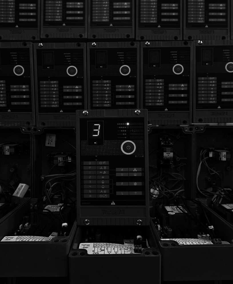
1 Electronics Permanent Operation Microprocessor Burner Control ESA ESTRO-PO (E7014PO rev /05/2013)
2 GENERAL WARNINGS: DISPOSAL: ¾ All installation, maintenance, ignition and setting must be performed by qualified staff, respecting the norms present at the time and place of the installation. ¾ To avoid damage to people and things, it is essential to observe all the points indicated in this handbook. The reported indications do not exonerate the Client/User from observing general or specific laws concerning accidents and environmental safeguarding. ¾ The operator must wear proper DPI clothing (shoes, helmets...) and respect the general safety, prevention and precaution norms. ¾ To avoid the risks of burns or high voltage electrocution, the operator must avoid all contact with the burner and its control devices during the ignition phase and while it is running at high temperatures. ¾ All ordinary and extraordinary maintenance must be performed when the system is stopped. ¾ To assure correct and safe use of the combustion plant, it is of extreme importance that the contents of this document be brought to the attention of and be meticulously observed by all personnel in charge of controlling and working the devices. ¾ The functioning of a combustion plant can be dangerous and cause injuries to persons or damage to equipment. Every burner must be provided with certified combustion safety and supervision devices. To dispose of the product, abide by the local legislations regarding it. GENERAL NOTES: ¾ In accordance to the internal policy of constant quality improvement, ESA-PYRONICS reserves the right to modify the technical characteristics of the present document at any time and without warning. ¾ It is possible to download technical sheets which have been updated to the latest revision from the website. CERTIFICATIONS: ESA ESTRO conforms to the EN298 regulation according to the KIP /01 certificate issued by notified body ESA ESTRO conforms to the European Directives: Gas Directive 2009/142/CE, Low voltage directive 2006/95/CE, Electromagnetic immunity 2004/108/CE, in conjunction with the EN298, EN230 and EN The products conform to the Russian market requirements according to the GOST and GOSGORTEKHNADZOR. ¾ The burner must be installed correctly to prevent any type of accidental/undesired heat transmission from the flame to the operator or the equipment. ¾ The performances indicated in this technical document regarding the range of products are a result of experimental tests carried out at ESA-PYRONICS. The tests have been performed using ignition systems, flame detectors and supervisors developed by ESA-PYRO- NICS. The respect of the above mentioned functioning conditions cannot be guaranteed if equipment, which is not present in the ESA-PYRONICS catalogue, is used. ASSISTANCE/CONTACTS: Headquarters: Esa S.p.A. Via Enrico Fermi Curno (BG) - Italy Tel Fax esa@esacombustion.it International Sales: Pyronics International s.a. Zoning Industriel, 4ème rue B-6040 Jumet - Belgium Tel Fax marketing@pyronics.be 2
, combustion air, and is able to detect the flame signal via ionization sensors (electrodes) or UV radiation (UV-scan),")

3 ESA ESTRO is a microprocessor operated flame control device that controls gas and oil fired burners for continuous operation. This device safely controls one or two stage burners (pilot and main), combustion air, and is able to detect the flame signal via ionization sensors (electrodes) or UV radiation (UV-scan), continuously performing a periodic check of the flame sensor. The flame control device is equipped with a serial communication which allows remote burner control. The case is robust allowing the application of the control device near the burner. APPLICATIONS ¾One or two stage burners (pilot or main), with any type of capacity, with permanent or non-permanent operation. ¾Burners with electrode, unirod and UV detection (also combined). ¾Package burners with complete ignition cycle control (blower, air regulation valve, pressure switch and air flow switch). ¾Burners with air valve control for chamber purge, burner ignition and temperature regulation (heating/cooling) via external regulator command. ¾Plants with burner control via digital signals or ECS serial communication. ¾Personalized burner control via optional configuration cards. F7014POI03 CHARACTERISTICS GENERAL: ¾Voltage supply: 115 Vac or 230 Vac % ¾Frequency supply: Hz ¾Type of supply: phase-neutral, not appropriate for phase-phase systems ¾Neutral: suitable for ground and non ground neutral systems ¾No-load absorption: 5 VA max ¾Working temperature: 0 60 C ¾Storage temperature: C ¾Protection degree:ip54 (for wiring use specific glands) ¾Mounting position: any ¾Working environment: not suitable for explosive or corrosive environments ¾Container: Thermosetting glass fiber ¾Size: mm ¾Mass: g ¾Classified according to EN298 e EN230:configurable BOOLXK F7014POI04 3
4 CHARACTERISTICS INPUTS AND OUTPUTS: ¾Voltage to the flame detection probe: max 300 Vac ¾Minimum ionization current: 2,4 µa ± 0,3 µa ¾Current limits to the probe: 1 ma ¾Flame signal display: 0 90 µa ¾Detection probe type: electrode or scanner ESA UV-2 ¾Probe line length to electrode or UV-2 detection: < 30 m ¾Insulation between the probe conductors: > 50 MΩ (cables with double insulation or double protection) ¾HV cable length from ignition transformer: maximum 2 m ¾Distance between ignition electrode and burner mass: 3 mm ± 0,5 ¾Digital input voltage: the same as the supply voltage ¾Digital input absorption: max 5mA ¾Filter for digital input: RC 100 Ω - 0,47 µf Vac ¾Output voltage: the same as the supply voltage ¾Maximum current per single output: 1,5 A (2 A for ignition transformer) ¾Total maximum current for all outputs: 3.15A per 10 second / minute ¾Output protection fuse: 3.15A rapid (*) replaceable ¾Internal relay protection fuse: 4 A not replaceable ¾Instrument protection fuse: 1 A not replaceable ¾Minimum voltage supply to maintain output (EN230): 70Vac (version 115Vac) and 140Vac (version 230Vac) ¾EXP-2, EXP-4 and EXP5 expansion card input voltage: 24 Vac/Vdc, 115 Vac, 230 Vac ¾EXP-2, EXP-4 e EXP5 expansion card input absorption: max 5mA ¾EXP-2, EXP-4 e EXP5 expansion card output voltage: the same as the supply voltage ¾EXP-2, EXP-4 e EXP5 expansion card output maximum current: 2A (not protected by internal fuse) (*) On request it is possible to implement a fast fuse 4A. PARAMETERS: ¾Purging or waiting time before ignition: ¾1st gas stage safety time*: ¾Regulation delay time or 2nd gas stage safety time*: ¾Reaction time*: ¾Shut off purging or waiting time: ¾Accepted remote unlocks: ¾Flame sensor check on permanent operation: ¾Auto shut down for test with non permanent operation: ¾Behaviour at flame loss: ¾1st gas stage burner functioning: ¾Air valve functioning: 0 99 sec or 2 20 min 1 25 sec 0 25 sec 1 20 sec 0 99 sec or 2 4 min max 5 in 15 minutes in 1 hour in 24 hours configurable configurable configurable * These parameters must be set according to the norm that is applicable at the time of installation. 4
5 DESCRIPTION ESA ESTRO is a microprocessor flame control device equipped with inputs and outputs for controlling and supervising burners with permanent functioning, fit for applications in which the burners remain running for more than 24 hours. The instrument has four different versions: ¾ESA ESTRO-A: to be used for single stage burners with air valve control. Via the configuration software it is possible to chose the air valve behaviour. DIGITAL INPUT REMOTE CONTROL FLAME SIGNAL ESA ESTRO A IGNITION TRANSFORMER GAS VALVE AIR VALVE DIGITAL OUTPUT D7014POI01 ¾ESA ESTRO-B: to be used for double stage burners: 1st stage (pilot), 2nd stage (main). Via the configuration software it is possible to choose between the interrupted or continuous 1st stage burner functioning. DIGITAL INPUT REMOTE CONTROL FLAME SIGNAL ESA ESTRO B IGNITION TRANSFORMER 1ST STAGE GAS VALVE 2ND STAGE GAS VALVE DIGITAL OUTPUT D7014POI02 ¾ESA ESTRO-C: to be used for single gas stage burners with burner running output available (volt free contact SPST) DIGITAL INPUT REMOTE CONTROL FLAME SIGNAL ESA ESTRO C IGNITION TRANSFORMER GAS VALVE BURNER ON DIGITAL OUTPUT D7014POI03 5
6 ¾ESA ESTRO-Q: to be used for single stage burners in which control is done via serial line. REMOTE CONTROL FLAME SIGNAL ESA ESTRO Q IGNITION TRANSFORMER GAS VALVE D7014POI04 The ESA ESTRO-A, B and C versions also have a digital configurable input and output, in particular the digital input is necessary in high temperature applications to activate specific functioning (see Norm EN746-2), whilst the digital output is used to check the UV-2 sensor during permanent operation. Depending on the working time and on the type of burner flame detection, it is possible to define the sensor s check method by selecting from the internal check of the ionization probe every hour, external check of the UV-2 sensor via the dimming shutter every On the front panel, ESA ESTRO has a configurable local button, a phase indication display, a bargraph flame signal indicator as well as the infrared port for the configuration of certain parameters via a hand held programmer. Via the special programming software, the instrument allows the configuration of parameters and functioning modes according to the application needs. It is possible to personalize the air valve command or the digital output, select the digital input or front button behavior or change timers of certain phases, provided that the applihour or shut down every 24 hours for non permanent operation with UV-2. All the ESA ESTRO versions are equipped with the ESA ECS serial interface that allows to completely control the burner from remote, communicating via the ECS or Modbus-RTU protocols, both implemented as standard in the instrument. Via serial communication a complete check of the burner is possible: ignition and shut down, pilot and main burner control, air valve control, information on the status and value of the flame signal. POWER SUPPLY L N SAFETY LIMITS PLC FIELDBUS ECS BUS - + POWER LINE L N ESTRO-A A 3 5 ESTRO-B B A 3 5 ESTRO-C B L N + - * V + ESTRO-Q N - T N F G * 1 GAS AIR A 1 GAS GAS 2 1 GAS 1 GAS D7014POI05 cable norm at the time of installation is respected. ESA ESTRO runs the burner ignition cycle count, storing the number of activations of the first stage gas valve and then the second stage gas valve or air valve. Via the programming software or hand held (portable) programmer you can read the numbers of the cycles performed following maintenance of the valves and reset the meters. All the ESA ESTRO versions are equipped with a replaceable protection fuse that blows in case of failures in the connected devices. Furthermore there is a non replaceable 6
7 internal relay protection fuse that blows only in case of malfunctioning of the first. ESA ESTRO is supplied in a robust case in thermoset material, predisposed for the housing of the ignition transformer and for the outputs of the various connecting cables with external users. Expansion cards that allow further control of the burner devices or specific serial communication can be applied to all the versions. The installation of the expansion cards precludes the possibility of mounting the ignition transformer inside the instrument.the available expansions are indicated below: ¾ESA EXP-2: expansion that allows to control a package type burner, able to activate the air valve or blower, check the air pressure switch status and control the air damper during the prepurge and burner ignition phases. The EXP-2 expansion card can also be used only to control the air valve (for versions that are different from ESTRO-A). THERMOSTAT AIR PRESSURE SWITCH PURGE AIR FLOW OR DAMPER OPENED IGNITION AIR FLOW OR DAMPER CLOSED ESA EXP-2 AIR VALVE OR BLOWER OPEN AIR DAMPER CLOSE AIR DAMPER REGOLATION ENABLED D7014POI06 ¾ESA EXP-3: expansion allowing to interface the flame control with the most common field bus. For detailed information refer to specific data sheet E7015. PROFIBUS-DP DEVICE-NET ETHERNET ESA EXP-3 D7014POI07 ¾ESA EXP-4: expansion having four digital inputs and four digital outputs as well as an analogical input and output, and a serial interface that allows to control the card from remote. For detailed information refer to specific data sheet E7016. DIGITAL INPUT 1 DIGITAL OUTPUT 1 DIGITAL INPUT 2 DIGITAL INPUT 3 DIGITAL INPUT 4 ANALOGIC INPUT ESA EXP-4 DIGITAL OUTPUT 2 DIGITAL OUTPUT 3 DIGITAL OUTPUT 4 ANALOGIC OUTPUT D7014POI08 ¾ESA EXP-5: expansion that has four digital inputs and four digital outputs with predefined functions. For detailed information refer to the specific data sheet E
8 DISPLAY AND LOCAL BUTTON SECTION DISPLAY ESA ESTRO displays different codes to indicate the flame control functioning and lockout statuses. Fixed symbols indicate normal operating conditions or certain non resettable faults, whilst lock or resettable fault conditions are indicated by flashing symbols. Normal operation phases DISPLAY STATUS DESCRIPTION FIXED Auto diagnosis phase in which the instrument checks the effciency of its internal components. This phase is carried out each time the device is powered or every time the burner is reignited (duration of about 2s). Waiting phase in which the instrument waits for the condition to be unlocked by the operator. It can be unlocked by the local button, remote button or by serial communication. This phase only occurs at power on when the Cycle start parameter is programmed on Stand-by. FIXED FIXED FIXED FIXED FIXED FIXED FIXED Stopping phase for adjustment requested by the thermostat. The instrument keeps the burner off and waits for the ignition command, forces the air damper to close and deactivates the other outputs. Air pressure switch waiting phase after having activated the air valve (or combustion blower), or burner stop waiting for the air pressure switch during normal operation regime. This last behaviour occurs when the Air pressure switch parameter is programmed on Waiting. Air damper opening phase waiting for the limit switch of the maximum position reached or for the minimum purge flow switch (FSL) consent, to purge with maximum air flow. This phase occurs with expansion cards when the Air flow or damper switch control parameter is programmed on Local, Remote or FSL enable purge, or if the function assigned to the digital input is FSL enable purge. Chamber purging or waiting phase before burner ignition. In applications with controlled cooling, this status indicates the phase in which only the air valve is on. During this phase flame absence is checked otherwise lockout is determined due to illegal flame. Air damper closing phase waiting for the limit switch of the minimum position reached or for the consent from the maximum ignition flow switch (FSH) consent, to carry out ignition at minimum power. This phase only occurs with expansion cards when the Air flow or damper switch control parameter is programmed on Local, Remote or FSH enable ignition, or if the function assigned to the digital input is FSH enable ignition. 1st stage burner ignition phase, lasting the same amount of time as the first safety time. The instrument activates the ignition transformer and 1st gas stage solenoid valve, then at the end, deactivates the transformer and checks the flame formation. 1st stage burner flame stability check phase: at the end of this the instrument checks the efficiency of the flame amplifier. This phase also occurs following a shut down command of the 2nd stage burner. FIXED Regime phase for ESTRO-A, ESTRO-C and ESTRO-Q versions. For ESTRO- B it is the 2nd stage burner ignition phase, lasting the same amount of time as the second safety time. The instrument activates the 2nd gas stage solenoid valve keeping the 1st gas stage on. This is a regime condition for the ESTRO- B when the 1st stage gas outlet type is programmed on Intermittent. 8
9 DISPLAY STATUS DESCRIPTION FIXED FIXED FIXED FIXED DOT FIXED DOT Regime phase for ESA ESTRO-B with only 2nd stage burner on. The instrument intercepts the 1st stage solenoid valve. This phase occurs only when the 1st stage gas outlet type parameter is programmed on Interrupted. Regime phase with air valve on. In case the Air pressure switch parameter is programmed on Lockout o Waiting" the instrument waits for the pressure switch signal before indicating this phase, whilst if Disable is programmed the transition to this phase corresponds with the activation of the air valve. This phase occurs only when the Air flow control mode parameter is programmed on Discontinue or Pulse. Detection system check phase in which the instrument verifies that the flame is extinguished in a maximum time of 20 seconds after burner shut down, otherwise there is lockout for illegal flame. Chamber purging or waiting phase following burner shut down. During this phase the instrument does not accept any command and displays the phase or lockout code that caused shut down, besides the fixed decimal point. Stop phase for regulation requested by serial communication. The instrument keeps the burner off, waits for an ignition command, forces the air shutter to close and deactivates all the other outputs. High temperature functioning on. During this operation the instrument displays the lockout or phase code, besides the flashing decimal point. If the high temperature function provides only the prepurge exclusion, this indication is present in all the phases prior to the ignition of the burner. Lockout or failure DISPLAY STATUS DESCRIPTION Manual stop generated by the operator via the local or remote button when the burner is in a normal operation phase. The instrument keeps the burner off and waits for the unlock that can be given by local button, remote button or serial communication. Lockout due to the detection of an illegal flame, during the phases before the burner ignition phase or after the shut down phase. The causes can be found in the detection system (broken probe or presence of humidity in UV-2) or in a gas leakage from the solenoid safety valve that allows the burner to remain on. Lockout due to the missing flame formation during 1st gas stage burner ignition. The causes can be found in the ignition system (no spark from the electrodes or broken transformers), in the bad flow regulation of fuel and combustion agents, or in the detection system (broken probe, interrupted cables, ground not connected). Specifically, in the first two cases the flame does not ignite, whilst in the last case the flame forms but ESA ESTRO is unable to detect it. Lockout due to the flame signal loss during normal burner operation. The causes can be found in the flow regulation of combustion air and fuel (rapid flow variations, regulation out of allowed range). Furthermore, this lockout condition is due to malfunctioning of the sensibility probe dimming shutter when permanent operation is on with UV detection, if this does not open after the hourly check. 9
10 DISPLAY STATUS DESCRIPTION FISSA Lockout due to the extended absence of serial commands by the remote supervisor, for a longer period of time than the period programmed in the Communication timeout parameter. Malfunctioning is due to the presence of the air pressure switch signal before the instrument has activated the combustion blower. The causes can be found in the incorrect wiring or in a fault in the air pressure switch. During normal operation, this indication appears for a few seconds during the air pressure signal test. Lockout due to the malfunctioning of the internal circuit related to the air pressure switch input. If after an attempt to reset, the problem reoccurs, the instrument must be sent back to the manufacturer. Lockout due to the missing air pressure switch signal during normal burner operation. The causes can be found in the combustion air flow (blocked filters, blower off) or in a pressure switch failure. Lockout due to the presence of the maximum position limit switch signal or minimum purge flow switch (FSL), before the instrument has commanded the air damper to open. Furthermore, this lockout can occur when the prepurge FSL check is on, but when the signal is received the input test result is negative. The causes can be found in the incorrect wiring or regulation of the air shutter limit or flow switch. Lockout due to the presence of the minimum position limit switch signal or maximum ignition flow switch (FSH), before the instrument has commanded the air damper to close. Furthermore, this lockout can occur when only the FSH ignition check is on, but when the signal is received the input test result is negative. The causes can be found in the incorrect wiring or regulation of the air shutter limit or flow switch. Lockout due to the failure of the air damper to close at the end of purging. The instrument waits for the minimum position limit switch signal for a maximum of 150 seconds from the closing command. The causes can be found in the incorrect wiring or regulation of the air damper limit or flow switch. Lockout due to failed power consumption by the electric devices connected to the instrument (ignition transformer or solenoid valves). The causes can be found in the breaking of one of the ignition devices, output protection fuse, in an interrupted electric connection or if the non resettable protection fuse of the internal relays is broken. In the last case the instrument must be sent to the manufacturer. Lockout due to a failure in the flame detection probe. The causes can be found in the breaking of the probe, a short circuit of the probe or in its ground connection (burner body), in the inverted connection of the ESA UV-2 sensibility probe, in the incorrect ground connection of the instrument or in the strong currents on the furnace mass (welding machines operating, etc). Lockout due to malfunctioning of the internal flame amplifier detected after ignition or during the periodic check or the flame amplifier sensor. Furthermore this lockout is due to the malfunctioning of the dimming shutter probe when the permanent operation with UV detection is running. The causes can be found in the incorrect wiring or in the functioning of the UV-2 shutter. Otherwise, if after an attempt to reset the problem reoccurs, the instrument must be sent back to the manufacturer. Lockout due to the malfunctioning of the internal circuit related to the thermostat input. If after an attempt to reset the problem reoccurs, the instrument must be sent back to the manufacturer. 10
11 DISPLAY STATUS DESCRIPTION Lockout due to an error in the internal memory reading. The failure can be temporary or final. The causes can be found in the incorrect connection to ground of the instrument or of the connected ignition devices, in the missing suppression filter in the ignition electrode connector, or else in the strong electromagnetic disturbances in the atmosphere or in the power supply. If after an attempt to reset the problem reoccurs, the instrument must be sent back to the manufacturer. Lockout due to missing communication with the optional card, if the presence of the expansion card has been configured. The causes can be found in the incorrect programming or in a card failure; in the first case check the programming, whilst in the second case if after an attempt to reset the problem reoccurs, the instrument must be sent back to the manufacturer. Lockout due to a short circuit in the internal command relay. If after an attempt to reset the problem reoccurs, the instrument must be sent back to the manufacturer. FIXED (1) FIXED (1) FIXED (1) FIXED (1) Malfunctioning due to the front button or the digital input button (if the reset/stop function from remote is on) that are blocked as if pressed during the auto diagnosis of the instrument. The causes can be found in the connection and control of the remote reset, in the possible absence of the RC filter, or front button failure. To reset the alarm, cut off the power to the instrument for a few seconds. Malfunctioning due to memory corruption or a failure in the safety system. The failure can be temporary or final. The causes can be found in the incorrect ground connection of the instrument or of the connected devices, in the missing suppression filter in the ignition electrode connector, or else in the strong electromagnetic disturbances in the atmosphere or in the power supply. To reset the alarm, cut off the power to the instrument for a few seconds. If the problem reoccurs, the instrument must be sent back to the manufacturer. Malfunctioning due to a short circuit in the internal safety relay. To reset the alarm, cut off the power to the instrument for a few seconds. If the problem reoccurs, the instrument must be sent back to the manufacturer. Malfunctioning due to a short circuit between the pins and the microprocessor. If the problem reoccurs, the instrument must be sent back to the manufacturer. FIXED (1) Malfunctioning due to a gap in the program. The causes can be found in the incorrect ground connection of the instrument or of the connected ignition devices, in the missing suppression filter in the ignition electrode connector, or else in the strong electromagnetic disturbances in the atmosphere or in the power supply. To reset the alarm, cut off the power to the instrument for a few seconds. If the problem reoccurs, the instrument must be sent back to the manufacture DISPLAY AND BARGRAPH Mlafunctioning due to excessive ambient temperature that does not allow the instrument to work. When this malfunctioning occurs the instrument continues to switch on and off displaying only the beginning of the auto diagnosis phase. (1) (1) The indication of these failures or lockout conditions starts flashing when power is supplied again, indicating that alarm reset is possible. 11
12 Configuration DISPLAY STATUS DESCRIPTION FIXED Programming phase from serial input via the special configuration software. During this phase it is not possible to carry out any other operation. FIXED Programming phase from infrared input via the special programmer. Fase di programmazione da ingresso infrarosso tramite l apposito programmatore. During this phase it is not possible to carry out any other operation. BARGRAPH ESA ESTRO has a bargraph with five leds indicating the flame value detected in a range of 0µA to 90µA. If the detection current is greater than 90µA the upper led is kept on. The flame detection signals generated by electrodes (ionization) are sensibly lower that compared with the signals generated by the UV probe, however, in both cases the stability of the indication on the bargraph is related to the stability of the signal detected by the burner flame. LOCAL BUTTON ESA ESTRO allows the configuration of the local button according to the application needs (see Configuration Parameter paragraph). The button can carry out the lock and manual stop functions as well as only lock or only manual stop or else it can be disabled with the possibility of being activated by serial communication. The button action differs depending on the function: ¾Unlock: the local button must be kept pressed for 1 to 3 seconds and when released ESA ESTRO unlocks the condition. If pressed for less or longer than specified, the command is not accepted. ¾Halt in manual stop: as soon as the local button is pressed, ESA ESTRO activates the halt. 12
13 FUNCTIONING ESA ESTRO is a configurable device for burner control that, depending on the set parameters, can assume different behaviour or determine different actions (see Configuration parameters). Below there is a description of the main functions or locks. BURNER IGNITION CYCLE The following diagram indicates an ignition cycle when the EXP-2 expansion card has been installed to control a package burner with first gas stage output interrupted. D7014POI
14 BURNER IGNITION CYCLE The following diagram indicates an ignition cycle of ESA ESTRO-B version without EXP-2 expansion card with first gas stage output interrupted. COMPLETE CYCLE D7014POI10 IGNITION BEHAVIOUR The following diagrams indicate the behaviour at instrument powering according to the Cycle start parameter if configured on Autostart or Standby. AUTOSTART D7014POI
15 STANDBY In the following diagram we have indicated the ESA ESTRO-B ignition cycle without EXP-2 expansion card. STAND-BY D7014POI12 ILLEGAL FLAME The following diagram indicates the behaviour in the presence of an illegal flame at burner ignition or shut down IN FAULT d D7014POI
16 FAILED IGNITION The following diagram indicates the behaviour in case of 1st gas stage ignition failure. IN FAULT U D FLAME SIGNAL LOSS The following diagram indicates the behaviour if the flame signal is lost with burner in regime phase and with the Behaviour at flame loss parameter configured on Lockout stop. IN FAULT F D
17 CONFIGURATION PARAMETERS The configuration defines the ESA ESTRO functioning mode, adapting it to the needs of the plant. Certain configuration parameters are defined and blocked by the factory in conformity to the related application norms. Others instead, can be altered by the user with the aid of suitable equipment. The modification of the parameters is accepted by the ESA ESTRO when it is in the manual stop condition and can be done with a portable programmer or dedicated software via a serial interface card. The portable programmer communicates via infrared interface and allows the serial communication parameters to be altered. The software installed on the pc instead, communicates via the ECS serial interface and allows all the non blocked parameters to be altered. With the aid of the software, the user can block other parameters, with the restriction that the blocks can only be removed by the manufacturer or by the person who entered them. Configuration via the ECS serial interface is allowed for one instrument at a time, and it is compulsory to disconnect the network on field and connect it directly to the ECS interface card connected to the PC. Non blocked parameters PARAMETER N NAME VALUE DESCRIPTION / Address Segment 0 9 and A Z capital letters With Address Segment the device is indentified for serial communication. The ECS protocol identifies the zone or the group to which it belongs. With Modbus-RTU protocol the address tens are defined (0 F for 0 16 tens). / Address Node 0 9 and A Z capital letters With Address Node the device is indentified for serial communication. The ECS protocol identifies the unit inside the zone or group. With Modbus-RTU protocol the address units are defined (0 9 units). 2 Cycle start 3 Prepurge time Automatic ignition Autostart Standby 0 99 sec 2 20 min When powered the instrument automatically starts the ignition cycle, at less than one block before shut down. This configuration is useful when controlling the burner through the power of the instrument. At power on the instrument does not start the ignition cycle but waits for the local or remote ignition command. This configuration is useful when controlling the the burner through serial communication to avoid simultaneous ignitions or for applications that require operator action every time. Chamber purge or waiting time before burner ignition. In applications with air shutter or flow control, the timing starts at maximum opening or with target purge flow (FSL). 5 Regulation delay time 2 safety time 0 25 sec Waiting time following the stability check phase of the 1st gas stage, after which air valve regulation is allowed (ESTRO-A and expansions). For the ESA ESTRO-B version this time corresponds to the second safety time (2nd gas stage ignition), for which the parameter is blocked and cannot be changed. Furthermore, when this time has expired, the 1st gas stage shuts down when it is interrupted. 7 Behaviour at flame failure Lockout Recycle The instrument determines shut down in burner lockout, caused by flame signal extinction for longer than the time set in the Reaction time parameter (reset is required). The instrument performs a sequence of complete ignition (including prepurge) after the flame signal has disappeared. When burner ignition has taken place correctly, at the next flame extinction, the instrument performs another ignition sequence. 17
18 PARAMETER N NAME VALUE Respark DESCRIPTION The instrument performs burner reignition (excluding prepurge) after the flame signal has disappeared. When burner ignition has taken place correctly, at the next flame extinction, the instrument performs another reignition sequence. 7 Behaviour at flame failure Only one recycle The instrument performs a sequence of complete ignition (including prepurge) after the flame signal has disappeared. When burner ignition has taken place correctly, at the next flame extinction, the instrument performs burner lockout halt (reset is required). Only one respark The instrument performs burner reignition (excluding prepurge) after the flame signal has disappeared. When burner ignition has taken place correctly, at the next flame extinction, the instrument performs burner lockout halt (reset is required). 9 Postpurge flex 10 Postpurge time Inhibited Enable 0 99 sec 2 4 min Continue The instrument begins timing of the Post purge time from burner shut down due to a shut down request or lockout. The instrument begins timing of the Post purge time from the burner ignition phase. When this configuration is present, the Postpurge time becomes the minimum time between one burner ignition and the next. Chamber purge or waiting time before another ignition after burner shut down. During the postpurge phase the instrument does not accept any other command; whilst in applications with air damper control, during this phase the damper is commanded to open. Enabling the Postpurge flex function this time becomes the minimum time between one burner ignition and the next. The instrument activates the air valve (or blower) from the ignition request and keeps it on until burner shut down due a request or lockout. This selection is necessary when the output has to be on for the entire prepurge cycle and burner operation because it controls the combustion blower or air interception valve. When this configuration is present, the Air on and Air off commands have no effect. 12 Air flow control type Discontinue delayed 0 sec Pulse The instrument activates the air valve from the ignition request until the end of the purging phase. It deactivates the valve by passing instantaneously to the ignition phase and then activates it from the end of the Regulation delay time until the burner shuts off due to a shut down request or lockout. This selection is useful in applications having an air partializing valve that must be activated for controlled prepurge or cooling.when there is this configuration, the Air on and Air off commands have effect from the end of the regulation delay time. The instrument activates the air valve from the end of the regulation delay time until the burner shuts off due to a shut down request or lockout. This selection is useful in applications having an air partializing valve but that don t need to be activated for controlled prepurge or cooling. When there is this configuration, the Air on and Air off commands have effect for air valve control purposes. Remote The instrument activates the air valve output only from the ignition phase until the end of the regulation delay time. This configuration is used when the EXP-2 expansion card is present and via the negated blower output (NC contact), to interrupt the air valve remote command allowing minimum burner ignition. Discontinue delayed 3 sec The instrument maintains the same behaviour as when Discontinue delayed 0 sec is selected, with the difference being that from the valve closing command, it waits for 3 seconds before moving onto burner ignition, giving the valve time to close. 18
19 PARAMETER N NAME VALUE DESCRIPTION 12 Air flow control type Discontinue delayed 5 sec Discontinue delayed 10 sec The instrument maintains the same behaviour as when Discontinue delayed 0 sec is selected, with the difference being that from the valve closing command, it waits for 5 seconds before moving onto burner ignition, giving the valve time to close. The instrument maintains the same behaviour as when Discontinue delayed 0 sec is selected, with the difference being that from the valve closing command, it waits for 10 seconds before moving onto burner ignition, giving the valve time to close. Inhibited The state of the digital input is not checked by the instrument. Reset / Stop The digital input has a dual function: with burner on as soon as it activated it leads to manual stop; whilst with burner in stop or lockout, if activated from 1 to 3 seconds when released, burner lockout is activated. The instrument accepts 5 reset commands from remote in 15 minutes. Only stop The digital input is checked by the instrument only with burner running: as soon as it is activated it leads to burner manual stop. Only reset The digital input is checked by the instrument only with burner in stop or lockout: if activated from 1 to 3 seconds, when released burner lockout is activated. The instrument accepts 5 reset commands from remote in 15 minutes. Thermostat The digital input works as a thermostat alternatively at the expansion input: with input on, the instrument switches the burner on, whilst when the input is not on, it determines shut down. This configuration is possible if the EXP-2 expansion card is not installed. High temperature The digital input is used to activate high temperature functioning. This selection is possible only for certain industrial applications where it is allowed according to the EN746-2 and in the High temperature function parameter, the instrument behavior is defined when this configuration is present. The digital input controls the 2nd gas stage as an alternative to the serial commands: with input on and 1st gas stage burner running, the instrument switches on the 2nd gas stage burner; whilst with input off, it determines second gas stage burner shut down. 13 Digital input function Main burner on / off Air valve on / off The digital input controls the air as an alternative to the serial commands: with input on and 1st gas stage burner running the instrument activates the air; whilst with input deactivated, it determines shut down. This function is valid only when the type of air control is discontinuous or impulsive. FSL enable purge Via the flow switch (FSL) the digital input checks the presence of the minimum air flow needed to time purging, as an alternative to the expansion input. This configuration avoids the EXP-2 expansion card as it is necessary to check just this command. The appropriately programmed digital output, will supply the phase to the flow switch. FSH enable ignition Via the flow switch (FSH) the digital input checks the correct air flow for burner ignition, as an alternative to the expansion input. This configuration avoids the EXP-2 expansion card as it is necessary to check just this command. The appropriately programmed digital output, will supply the phase to the flow switch. Air pressure switch The digital input functions as an air pressure switch as an alternative to the expansion input. This configuration avoids the EXP-2 expansion card as it is necessary to check just this command. The instrument behavior depending on the pressure status, is always defined in the Air pressure switch parameter (parameter n 27). The appropriately programmed digital output, will supply the phase to the pressure switch. 19
20 PARAMETER N NAME 14 Digital output function VALUE Stop / fault Fault Burner ON Regolation consent Command NO shutter Command NC shutter Digital input control Remote enable DESCRIPTION The digital output indicates that the instrument is in lockout status, manual stop or waiting after power on (flashing display). The output is not activated during auto diagnosis. The digital output indicates that the instrument is in lockout status. The output is not activated during auto diagnosis, in manual stop status nor waiting after power on. The digital output indicates that the burner is on. The output is activated from the end of the ignition phase and remains on for all the burner functioning phases. The digital output allows burner regulation. It activated at the end of the Regulation delay time and remains on for the time that the burner is in regime. The behavior of this output is the same as the ready output of the EXP-2 expansion. The digital output controls the NO dimming UV-2 shutter, needed for periodic check during permanent functioning. Without any command, the shutter is normally open and the digital output is activated in the test phase to command the closing, determining the dimming of the UV-2 probe. The digital output controls the NC dimming UV-2 shutter, needed for periodic check during permanent functioning. Without any command, the shutter is normally closed and the digital output is deactivated in the test phase to command the closing, determining the dimming of the UV-2 probe. In the absence of the EXP-2 expansion, the digital output controls the phase sent to the air pressure or flow switches when the digital input takes on the FSL enable purge, FSH enable ignition or Air pressure switch functions. This selection is necessary to check the efficiency of the digital input when it carries out these functions. The front button is not checked by the instrument as the burner control takes place via serial communication. If the specific status request command is sent, the instrument activates the local button action and it takes on the Reset / Stop function to allow local maintenance operations. 15 Local botton Reset / stop The front button has dual function: with burner running, as soon as it is pressed, it determines manual stop; whilst with the burner in stop or lockout, if pressed for 1-3 seconds, when released, it unlocks the burner. Only stop The front button is checked by the instrument only with burner running: as soon as it is pressed it determines burner manual stop. Only reset The front button is checked by the instrument only with burner in stop or lockout: if it is pressed for 1-3 seconds, when released it unlocks the burner. 20 Communication timeout sec Time limit for serial communication absence, that can be set in ten steps from 0 to 480 seconds, after which the instrument activates the Comtimeout alarm, determining burner stop. Set this parameter at 0 to disable the Com-timeout alarm when serial communication is not used. 21 & 22 Communication Baudrate & Communication protocol ECS ModbusRTU ModbusRTU 2 Communication speed (4800, 9600, and Bit/s) with ECS protocol. The hardware interface is ECS, and it requires a specific converter. Communication speed (4800, 9600, and Bit/s) with Modbus RTU (1 stop bit) protocol. The hardware interface is ECS, and it requires a specific converter. Communication speed (4800, 9600, and Bit/s) with Modbus RTU (2 stop bit) protocol. The hardware interface is ECS, and it requires a specific converter. 20
21 PARAMETER N NAME 25 EXP Installed VALUE Inhibited Enable Inhibited DESCRIPTION The instrument does not control the expansion cards. This configuration is needed when the expansion cards are not installed or if the EXP-3 expansion is present. The instrument activates the expansion card control. This configuration is necessary when the EXP-2, EXP-4 and EXP-5 expansion cards are installed. The air pressure switch status is not checked. The missing air pressure switch signal implies: 27 Air pressure switch Waiting During the purge phase it determines the timer reset; With continuous type air control and burner on it determines shut down and waits for the signal to return (automatic reignition). With discontinuous or impulsive type air control, with burner on, it determines the status change for air deactivation. The missing air pressure switch signal implies: Lockout During the purge phase it determines the timer reset; With continuous type air control and burner on it determines shut down in lockout for lack of air (reset is required). With discontinuous or impulsive type air control, with burner on, it determines the status change for air deactivation Thermostat input Air flow or damper switch control Inhibited Enable Inhibited Local Remote The thermostat status connected to the expansion card is not checked. The instrument waits for the thermostat signal connected to the expansion card before switching the burner on. if there is no signal the burner is shut down and waits for the signal to return. The position of the air damper via the limit switch or the air flow detected via the flow switches, is not checked for prepruge or burner ignition phases. The instrument controls the air damper to regulate the air flow for purge and ignintion. To time the purging, the damper is commanded to open and the instrument checks the consent of the maximum position limit switch or the air presence flow switch (FSL) for purging. After this, to activate burner ignition, the damper is commanded to close and the instrument checks the consent of the minimum position limit switch or the maximum flow switch (FSH) for ignition. The air damper position or the air flow is not controlled by the instrument inputs, but by a remote supervisor, which sends specifics serial commands to the instrument to time the purging or to perform burner ignition according to the shutter position or air flow. This function used in the past is not used in recent applications. Only FSL The instrument checks the maximum air damper position limit switch or air presence flow switch for purging (FSL) to time the purging. Once prepurge timing is over, the instrument moves directly onto ignition. Only FSH The instrument checks the consent of the air damper minimum position limit switch or maximum ignition flow switch (FSH) to activate burner ignition. 21
22 Locked parameters PARAMETER VALUE N NAME 4 1 safety time 1 25 sec DESCRIPTION First safety time for ignition of the first gas stage (see table of allowed times). 6 1 stage gas outlet type Intermittent Interrupted The 1st gas stage burner is kept running even after the ignition of the 2nd gas stage, until both are shut down at the same time.this configuration is valid for the single stage versions (ESTRO A2, C2 and Q2), or for the ESTRO-B version that controls a double stage burner. When ESTRO-B controls a pilot burner separately from the main burner, check the applicability of the rules based on the application. The 1st gas stage burner is switched off after the 2nd gas stage has been stabilized. Shut down takes place after the Regulation delay /2nd safety time that in this case corresponds to the 2nd safety time. This configuration is possible only for the ESTRO-B version that controls the pilot burner separately from the main burner. Not permanent (stop every 24 hours) After 24 hours of continuous operation of the burner, the instrument activates shut down to perform efficiency test of the flame detection probes and auto diagnosis. This functioning is useful for not permanent operation burners detected by UV-2. This configuration avoids installing the shutter for the UV-2 probe. 11 Burner functioning mode Permanent with detection rod Permanent with UV and shutter Every hour of continuous burner operation, the instrument checks the flame amplifier by disconnecting the flame signal from the detection electrode. This selection is allowed only with ionization flame detection via electrode. Every hour of continuous burner operation, the instrument checks the flame amplifier and the UV-2 sensibility probe, by dimming the UV radiation coming into the probe. Dimming occurs via a shutter placed between the probe and the burner. This selection is allowed only with flame UV-2 sensor flame detection. 0 The instrument never attempts reignition in lockout conditions. 1 9 generic lockout Maximum number of automatic recycle attempts (including prepurge), performed by the flame control regardless of the lockout cause. The attempts are done consecutively and only signal the lockout status to remote at the end of all the attempts. When this function is enabled, the instrument conforms only to the EN746-2 Norm. 16 Automatic ignition trial 1 5 recycle for U lockout Maximum number of automatic recycle attempts (including prepurge), performed by the flame control after failed ignition (U lockout). The attempts are done also non consecutively and only signal the lockout status to remote at the end of all the attempts. When this function is enabled, the instrument conforms only to the EN746-2 Norm. 1 5 respark for U lockout Maximum number of automatic reignition attempts (excluding prepurge), performed by the flame control after failed ignition (U lockout). The attempts are done also non consecutively and only signal the lockout status to remote at the end of all the attempts. When this function is enabled, the instrument conforms only to the EN746-2 Norm. 22
23 PARAMETER N NAME VALUE Inhibited Only flame bypass DESCRIPTION The instrument never activates the high temperature function even after the specific command from the digital input. The instrument activates the high temperature function with the sole function of flame bypass for the time in which the specific digital input command is present. With this high temperature function on, the instrument keeps the gas valves open regardless of the flame presence signal. When this function is enabled, the instrument conforms only to the EN746-2 Norm, and the command to the digital input must come from the protection system. 17 High temperature function Only prepurge exclusion The instrument activates the high temperature function with the sole function of prepurge exclusion for the time in which the specific digital input command is present. With this high temperature function on, the instrument does not carry out the prepurge phase but skips directly to burner ignition, monitoring the flame signal.when this function is enabled, the instrument conforms only to the EN746-2 Norm, and the command to the digital input must come from the protection system. Flame bypass and prepurge exclusion The instrument activates the high temperature function with prepurge exclusion and flame bypass function for the time in which the specific digital command is present. With this high temperature function command on, the instrument does not carry out the prepurge phase but skips directly to burner ignition, keeping the gas valves open regardless of the flame signal presence. When this function is enabled, the instrument conforms only to the EN746-2 Norm, and the command to the digital input must come from the protection system stage gas ignition type Fixed Variable 19 Reaction time 1 20 sec The duration of the first gas safety time for 1st gas stage ignition is fixed. The instrument checks the flame formation only at the end of the 1st safety time after having deactivated the ignition transformer.this configuration is compulsory with systems having unirod or UV2 probe type detection. The duration of the first safety time can be reduced automatically, to immediately reach the regime phase (pulse firing). The instrument continuously checks the flame formation during the ignition phase and as soon as it checks its presence, it deactivates the ignition transformer and passes onto the next phase. This configuration is possible only with systems having detection with a dedicated electrode. Maximum safety time allowed between flame signal absence and gas valve interception (see table of allowed times). If the flame signal returns before the time expires, the instrument keeps the current phase, otherwise it determines the behaviour configured in the Behaviour at flame loss parameter. For the ESA ESTRO-B version the Regulation delay time 2 safety time parameter corresponds to the second safety time, therefore the parameter is blocked and cannot be altered (see description of parameter 5). 23
Burners. Pilot Heads BTC & BTSA (E3121 rev /04/2018)
") Burners Pilot Heads BTC & BTSA (E3121 rev. 02-24/04/2018) GENERAL WARNINGS: DISPOSAL: ¾ All installation, maintenance, ignition and setting must be performed by qualified staff, respecting the norms present
Burners Pilot Heads BTC & BTSA (E3121 rev. 02-24/04/2018) GENERAL WARNINGS: DISPOSAL: ¾ All installation, maintenance, ignition and setting must be performed by qualified staff, respecting the norms present
Valves. Rapid opening and closing solenoid valves VMR (E1110 rev /11/2012)
") Valves Rapid opening and closing solenoid valves VMR (E1110 rev. 03-19/11/2012) GENERAL WARNINGS: DISPOSAL: ¾ All installation, maintenance, ignition and setting must be performed by qualified staff, respecting
Valves Rapid opening and closing solenoid valves VMR (E1110 rev. 03-19/11/2012) GENERAL WARNINGS: DISPOSAL: ¾ All installation, maintenance, ignition and setting must be performed by qualified staff, respecting
Orifice Flow Meters POP-S (E5720 rev /03/2013)
") Accessories Orifice Flow Meters POP-S (E5720 rev. 05-20/03/2013) GENERAL WARNINGS: DISPOSAL: ¾ All installation, maintenance, ignition and setting must be performed by qualified staff, respecting the norms
Accessories Orifice Flow Meters POP-S (E5720 rev. 05-20/03/2013) GENERAL WARNINGS: DISPOSAL: ¾ All installation, maintenance, ignition and setting must be performed by qualified staff, respecting the norms
Electronics. Permanent operation microprocessor burner control device ESA GENIO-S (E7021 rev /05/2015)
") Electronics Permanent operation microprocessor burner control device ESA GENIO-S (E7021 rev. 01-06/05/2015) GENERAL WARNINGS: GENERAL NOTES: ¾ All installation, maintenance, ignition and setting must be
Electronics Permanent operation microprocessor burner control device ESA GENIO-S (E7021 rev. 01-06/05/2015) GENERAL WARNINGS: GENERAL NOTES: ¾ All installation, maintenance, ignition and setting must be
Electronics. Permanent operation microprocessor burner control device ESA GENIO-PRS (E7022 rev /05/2015)
") Electronics Permanent operation microprocessor burner control device ESA GENIO-PRS (E7022 rev. 01-13/05/2015) GENERAL WARNINGS: GENERAL NOTES: ¾ All installation, maintenance, ignition and setting must
Electronics Permanent operation microprocessor burner control device ESA GENIO-PRS (E7022 rev. 01-13/05/2015) GENERAL WARNINGS: GENERAL NOTES: ¾ All installation, maintenance, ignition and setting must
Burners. Pilot Heads BTC & BTSA (E3121 rev /09/2010)
") Burners Pilot Heads BTC & BTSA (E3121 rev. 01-06/09/2010) GENERAL WARNINGS: DISPOSAL: ¾ All installation, maintenance, ignition and setting must be performed by qualified staff, respecting the norms present
Burners Pilot Heads BTC & BTSA (E3121 rev. 01-06/09/2010) GENERAL WARNINGS: DISPOSAL: ¾ All installation, maintenance, ignition and setting must be performed by qualified staff, respecting the norms present
Valves. Slow opening and rapid closing solenoid valves VM-L (E1111 rev /11/2012)
") Valves Slow opening and rapid closing solenoid valves VM-L (E1111 rev. 03-19/11/2012) GENERAL WARNINGS: DISPOSAL: ¾ All installation, maintenance, ignition and setting must be performed by qualified staff,
Valves Slow opening and rapid closing solenoid valves VM-L (E1111 rev. 03-19/11/2012) GENERAL WARNINGS: DISPOSAL: ¾ All installation, maintenance, ignition and setting must be performed by qualified staff,
Burners. Metallic free flame burners. EMB (E3004 rev /02/2010)
") Burners Metallic free flame burners EMB (E3004 rev. 06-11/02/2010) GENERAL WARNINGS: DISPOSAL: ¾ All installation, maintenance, ignition and setting must be performed by qualified staff, respecting the
Burners Metallic free flame burners EMB (E3004 rev. 06-11/02/2010) GENERAL WARNINGS: DISPOSAL: ¾ All installation, maintenance, ignition and setting must be performed by qualified staff, respecting the
E Series CE Approved Intermittent Pilot Ignition Control
 Installation Instructions Issue Date January 11, 2013 E Series CE Approved Intermittent Pilot Ignition Control Application The E Series CE Approved Intermittent Pilot Ignition Control is a safety control
Burners. Ribbon linear flame burners AB & ABM (E3010 rev /11/2017)
") Burners Ribbon linear flame burners AB & ABM (E3010 rev. 09-14/11/2017) GENERAL WARNINGS: DISPOSAL: ¾ All installation, maintenance, ignition and setting must be performed by qualified staff, respecting
Burners Ribbon linear flame burners AB & ABM (E3010 rev. 09-14/11/2017) GENERAL WARNINGS: DISPOSAL: ¾ All installation, maintenance, ignition and setting must be performed by qualified staff, respecting
Free flame burners EMB (E3004 rev /02/2015)
") Burners Free flame burners EMB (E3004 rev. 08-10/02/2015) GENERAL WARNINGS: DISPOSAL: ¾ All installation, maintenance, ignition and setting must be performed by qualified staff, respecting the norms present
Burners Free flame burners EMB (E3004 rev. 08-10/02/2015) GENERAL WARNINGS: DISPOSAL: ¾ All installation, maintenance, ignition and setting must be performed by qualified staff, respecting the norms present
OIL REGULATORS RFG SERIES FEATURES APPLICATIONS DESCRIPTION INSTALLATION. Bulletin E5301 rev03 02/04/03. Body and valve seat: Shutter seat:
 OIL REGULATORS RFG SERIES FEATURES Body and valve seat: AVP Shutter seat: C40 Valve stem: AISI303 Diaphragm: anti-petrol rubbered fabrics Max viscosity: 3 E Max operating pressure: 7 bar Max differential
Burners. High velocity LOW NOx combustion air burners EMB-SIK-NxT (E3507 rev /11/2016)
") Burners High velocity LOW NOx combustion air burners EMB-SIK-NxT (E3507 rev. 05-28/11/2016) GENERAL WARNINGS: GENERAL NOTES: ¾ All installation, maintenance, ignition and setting must be performed by qualified
Burners High velocity LOW NOx combustion air burners EMB-SIK-NxT (E3507 rev. 05-28/11/2016) GENERAL WARNINGS: GENERAL NOTES: ¾ All installation, maintenance, ignition and setting must be performed by qualified
G821L/G822L Series Integrated Function Direct Spark Ignition Controls
 Installation Sheets Manual 121 Gas Combustion Combination Controls and Systems Section G Technical Bulletin G821L/G822L Issue Date 1199 G821L/G822L Series Integrated Function Direct Spark Ignition Controls
Radiant tube burners RT (E3900 rev /01/2018)
") Burners Radiant tube burners RT (E3900 rev. 09-23/01/2018) GENERAL WARNINGS: DISPOSAL: ¾ All installation, maintenance, ignition and setting must be performed by qualified staff, respecting the norms present
Burners Radiant tube burners RT (E3900 rev. 09-23/01/2018) GENERAL WARNINGS: DISPOSAL: ¾ All installation, maintenance, ignition and setting must be performed by qualified staff, respecting the norms present
Burners. Self-recuperative burners high speed with flat flame REKO-SIK-SW (E3903 rev /06/2015)
") Burners Self-recuperative burners high speed with flat flame REKO-SIK-SW (E3903 rev. 01-08/06/2015) GENERAL WARNINGS: DISPOSAL: ¾ All installation, maintenance, ignition and setting must be performed by
Burners Self-recuperative burners high speed with flat flame REKO-SIK-SW (E3903 rev. 01-08/06/2015) GENERAL WARNINGS: DISPOSAL: ¾ All installation, maintenance, ignition and setting must be performed by
G72x Series Direct Spark Ignition Controls
 Installation Sheets Manual 121 Gas Combustion Combination Controls and Systems Section G Technical Bulletin G72x Issue Date 1299 G72x Series Direct Spark Ignition Controls Figure 1: G72x Direct Spark Ignition
G861 Series Integrated Function. Direct Spark Ignition Control
 Installation Sheets Manual 121 Gas Combustion Combination Controls and Systems Section G Technical Bulletin G861 Issue Date 0699 G861 Series Integrated Function Direct Spark Ignition Control Figure 1:
Valves. Double stage and modulant motorized butterfly valves MRBV & MRBV-CMAP (E1302 rev /04/2011)
") Valves Double stage and modulant motorized butterfly valves MRBV & MRBV-CMAP (E1302 rev. 04-07/04/2011) GENERAL WARNINGS: DISPOSAL: ¾ All installation, maintenance, ignition and setting must be performed
Valves Double stage and modulant motorized butterfly valves MRBV & MRBV-CMAP (E1302 rev. 04-07/04/2011) GENERAL WARNINGS: DISPOSAL: ¾ All installation, maintenance, ignition and setting must be performed
G76x Direct Spark Ignition Controls
 Installation Sheets Manual 121 Gas Combustion Combination Controls and Systems Section G Technical Bulletin G76x Issue Date 0400 G76x Direct Spark Ignition Controls Figure 1: G76x Direct Spark Ignition
SERIES VAC Microprocessor Based Direct Spark Ignition Control FEATURES DESCRIPTION APPLICATIONS THE TOTAL SOLUTION FOR GAS IGNITION CONTROL
 SERIES 35-72 120 VAC Microprocessor Based Direct Spark Ignition Control 35.72.03 FEATURES Two Mounting Configurations Open Board With Stand-Off's - saves space and cost Potted - protection for washdown
ECONOMISER SERIES E2T USER MANUAL
 TURBO S.R.L. Electronic Control Systems for Dust Collectors e-mail: info@turbocontrols.it web: www.turbocontrols.it TEL. ++39 (0)362 574024 FAX ++39 (0)362 574092 ECONOMISER SERIES E2T USER MANUAL 24/06/2014
G600 Series Replacement Intermittent Pilot Ignition Controls
 Installation Instructions G600 Issue Date 0601 G600 Series ment Intermittent Pilot Ignition Controls Installation IMPORTANT: These instructions are intended as a guide for qualified personnel installing
Modulating Furnace Information. Warning on Meter Setting - Read First!
 Modulating Furnace Information Pressure Transducer Pressure DC Volts 0.00" 0.25 0.20" 0.63 0.25" 0.72 0.30" 0.82 0.35" 0.91 0.40" 1.00 0.45" 1.09 0.50" 1.19 0.55" 1.28 0.60" 1.38 0.65" 1.47 0.70" 1.56
burners with or without fan. It conforms to EN C). APPROVAL EU type test approval as per EU Gas Appliance Directive.
. APPROVAL EU type test approval as per EU Gas Appliance Directive.") LAST UPDATE 29/08/12 INSTALLATION INSTRUCTIONS v. 3 UNIT SPECIFICATIONS Main Gas Valve, Pilot Gas Valve Ionisation, Ignition and Flame Monitoring with Common Electrode or Remote Sensor Integrated Cyclic
LAST UPDATE 29/08/12 INSTALLATION INSTRUCTIONS v. 3 UNIT SPECIFICATIONS Main Gas Valve, Pilot Gas Valve Ionisation, Ignition and Flame Monitoring with Common Electrode or Remote Sensor Integrated Cyclic
Burners. Self-recuperative burners high speed free flame REKO-SIK-FF (E3901FF rev /05/2009)
") Burners Self-recuperative burners high speed free flame REKO-SIK-FF (E3901FF rev. 04-06/05/2009) GENERAL WARNINGS: DISPOSAL: ¾ All installation, maintenance, ignition and setting must be performed by qualified
Burners Self-recuperative burners high speed free flame REKO-SIK-FF (E3901FF rev. 04-06/05/2009) GENERAL WARNINGS: DISPOSAL: ¾ All installation, maintenance, ignition and setting must be performed by qualified
TWO STAGE GAS BURNER GULLIVER RSD SERIES RS5D 160/ kw
 TWO STAGE GAS BURNER GULLIVER RSD SERIES 160/208 345 kw The Riello Gulliver is a new model of the series of two stage gas burners, characterized for its small dimensions in spite of its high combustion
ONE STAGE GAS BURNER GULLIVER RSF SERIES RS5F kw
 ONE STAGE GAS BURNER GULLIVER RSF SERIES 160 330 kw The Riello Gulliver, is a new model of the series of one stage gas burners, developed to respond to any request for light industrial processes like bakery
SYMBOL LEGEND DANGER WARNING NOTE THIS INDICATES DANGER TO THE LIFE AND HEALTH OF THE USER IS APPROPRIATE PRECAUTIONS ARE NOT TAKEN
 SYMBOL LEGEND DANGER THIS INDICATES DANGER TO THE LIFE AND HEALTH OF THE USER IS APPROPRIATE PRECAUTIONS ARE NOT TAKEN WARNING THIS WARNS THAT MATERIALS MAY BE DAMAGED IF APPROPRIATE PRECAUTIONS ARE NOT
Hayward error codes and troubleshooting
 http://waterheatertimer.org/intermatic-trippers-and-parts.html#pool 50 Hayward error codes and troubleshooting Section V. TROUBLESHOOTING http://www.hayward-pool.com/prd/in-ground-pool-manuals_10201_10551_14502_-1
3200NT Timer Service Manual
 Service Manual Valve Serial Number Valve Position 1-LEAd 2-LAg 3-LAg 4-LAg IMPORTANT: Fill in pertinent information on page 3 for future reference. Table of Contents Job Specifications Sheet.....................................................................
ORDERING INFORMATION SPECIFICATIONS APPLICATION
 ORDERING INFORMATION UNIVERSAL MODELS The ordering part number for the universal model is 82UNIVERSAL. The 82UNIVERSAL comes with remote flame sense active. For internal flame sense, the supplied universal
Observe all necessary safety precautions when controlling the soft starter remotely. Alert personnel that machinery may start without warning.
 Introduction OPERATING INSTRUCTIONS: MCD REMOTE OPERATOR Order Codes: 175G94 (for MCD 2) 175G361 + 175G9 (for MCD 5) 175G361 (for MCD 3) 1. Introduction 1.1. Important User Information Observe all necessary
Sheet n 1 of 20 Doc. n WDMM/02/E MOD. WDMM INSTALLATION, USE AND SERVICE MANUAL. PETROL INSTRUMENTS S.r.l APRILIA (LT) - ITALY
 - ITALY") Sheet n 1 of 20 WATER DRAW/ MASTER METER PETROL COUNTER MOD. WDMM INSTALLATION, USE AND SERVICE MANUAL PETROL INSTRUMENTS S.r.l. - 04011 APRILIA (LT) - ITALY Sheet n 2 of 20 INSTALLATION, USE AND SERVICE
Sheet n 1 of 20 WATER DRAW/ MASTER METER PETROL COUNTER MOD. WDMM INSTALLATION, USE AND SERVICE MANUAL PETROL INSTRUMENTS S.r.l. - 04011 APRILIA (LT) - ITALY Sheet n 2 of 20 INSTALLATION, USE AND SERVICE
HP21 SERVICE SUPPLEMENT UNIT INFORMATION. TSC6 Two-Speed Control
 SERVICE UNIT INFORMATION SUPPLEMENT HP21 Corp. 9426 L10 Litho U.S.A. All HP21-4 and -5 units (single and three phase) are equipped with a TSC6 two-speed control. The TSC6 (A14) two-speed control contains
Automatic concealed bollards 275 H600 and 275 H800 Control station
 Automatic concealed bollards 275 H600 and 275 H800 Control station Technical installation manual CE Declaration Warnings for the installer Bollard electrical connection Technical specifications for control
INSTRUCTION AND USE MANUAL
 CONTROL UNITS FOR ENGINE CONTROL AND PROTECTION TYPE CEP-090 INSTRUCTION AND USE MANUAL It is equipped with display to show the INSTRUMENTS: - hour-meter - fuel level indicator - tachometer - battery voltmeter
POWER SUPPLY UNIT FOR 3 KW MAGNETRON TECHNICAL NOTE
 POWER SUPPLY UNIT FOR 3 KW MAGNETRON TECHNICAL NOTE (Issue April 2004) CE Declaration of Conformity Dichiarazione di Conformità CE Manufacturer s Name: Nome del Costruttore: Manufacturer s Address: Indirizzo
Installation, Operation and Maintenance Manual. EVC Controller (from February 2007)
") Installation, Operation and Maintenance Manual (from February 2007) Publication 2698C (GB) 0207 1A 3319 8035B Donaldson reserve the right to alter design without notice. Freedom from patent restrictions
Installation, Operation and Maintenance Manual (from February 2007) Publication 2698C (GB) 0207 1A 3319 8035B Donaldson reserve the right to alter design without notice. Freedom from patent restrictions
BG1600M Intermittent Pilot Ignition Control
 Installation Instructions Issue Date March, 00 BG600M Intermittent Pilot Ignition Control Application The BG600M Intermittent Pilot Ignition Control is a safety control designed for indirect burner ignition
Compact Heat Meters. Features. -A Pulsed output. -B M-Bus output. Accessories. UK Sales Tel: International Tel:
 Compact Heat Meters Features Compact design Simple operation Pulsed output Measures heating or cooling Specification Product Codes Water Meter Temp. range 10 to 90 C Nominal pressure 16bar Installation
S4562C 1085 COMBI BOARD APPLICATION. Contents PRODUCT HANDBOOK. General
 S4562C 1085 COMBI BOARD APPLICATION PRODUCT HANDBOOK The S4562C 1085 combi board is an integration of an on/off temperature control and an electronic ignition control. The S4562C 1085 combi board is intended
GeniSys 24V. Model Advanced 24 Vdc Burner Control. Description / Applications
 PARTS & ACCESSORIES GeniSys 24V Model 7559 Advanced 24 Vdc Burner Control Description / Applications The Beckett GeniSys TM 24V Advanced Burner Control is a 24 Vdc primary safety control for oil burners
SYMBOL LEGEND DANGER WARNING NOTE THIS INDICATES DANGER TO THE LIFE AND HEALTH OF THE USER IS APPROPRIATE PRECAUTIONS ARE NOT TAKEN
 SYMBOL LEGEND DANGER THIS INDICATES DANGER TO THE LIFE AND HEALTH OF THE USER IS APPROPRIATE PRECAUTIONS ARE NOT TAKEN WARNING THIS WARNS THAT MATERIALS MAY BE DAMAGED IF APPROPRIATE PRECAUTIONS ARE NOT
USER INSTRUCTIONS FOR SLIDING DOORS
 ENGLISH USER INSTRUCTIONS FOR SLIDING DOORS SL3L LIGHT SL4A ADVANCED SL5A ADVANCED SL5H HEAVY SLTA TELESCOPIC-ADVANCED SL4E EMERGENCY SL5E EMERGENCY SL5B BIG SLTE TELESCOPIC-EMERGENCY FACE S.p.A. Viale
PROFIRE 1100i IGNITION FLAME SAFETY CONTROLLER
 PROFIRE 1100i IGNITION FLAME SAFETY CONTROLLER Cautions WARNING: EXPLOSION HAZARD- -DO NOT SERVICE UNLESS AREA IS KNOWN TO BE NON- HAZARDOUS -DO NOT OPEN WHEN ENERGIZED EXPLOSION HAZARD- -SUBSTITUTION
RS SERIES. Two Stage Progressive Gas Burners FIRING RATES
 The RS burners series covers a firing range from 44 to 2290 kw, and it has been designed for use in low or medium temperature hot water boilers, hot air or steam boilers, diathermic oil boilers. Operation
Whad 0.8, 1, 1.5 kva. Manuel d installation Installation manual. Part. LE05733AA-07/12-01 GF
 Manuel d installation Installation manual Part. LE05733AA-07/12-01 GF Index 1 Introduction 18 2 Conditions for use 19 3 Installation 20 4 Visual and acoustic warning signals 22 5 ups diagnostic software
LOW NOx TWO STAGE GAS BURNERS GULLIVER BSD SERIES BS1D 16/19 52 kw BS2D 35/40 91 kw BS3D 65/ kw BS4D 110/ kw
 LOW NOx TWO STAGE GAS BURNERS GULLIVER BSD SERIES 1/19 5 kw 35/4 91 kw 5/75 19 kw 11/14 4 kw The Riello Gulliver BSD series of two stage gas burners, is a complete range of Low NOx emission products, developed
ONE STAGE GAS BURNERS RS/1 SERIES RS 28/ kw RS 34/1 MZ kw RS 38/ kw RS 44/1 MZ kw
 ONE STAGE GAS BURNERS RS/1 SERIES RS 28/1 163 349 kw RS 34/1 MZ 7 39 kw RS 38/1 232 465 kw RS 44/1 MZ 55 kw The RS/1 series of burners covers a firing range from 7 to 55 kw, and they have been designed
RS/1 SERIES. One Stage Gas Burners RS 34/1 MZ RS 44/1 MZ kw kw GAS
 The RS/1 series of burners covers a firing range from 70 to 550 kw, and they have been designed for use in low or medium temperature hot water boilers, hot air or steam boilers, diathermic oil boilers.
RS/M SERIES. Modulating Gas Burners FIRING RATES
 The RS/M burners series covers a firing range from 45 to 2650 kw, and it has been designed for use in low or medium temperature hot water boilers, hot air or steam boilers, diathermic oil boilers. Operation
TTT802 Gearshift Controller, Part # R1N-S (Standard), -P (Paddleshift)
, -P (Paddleshift)") First, Sign and Date Bln 2009-03-9 Updated, Sign and Date Bln 200-04-29 (0) User Manual TTT802 Gearshift Controller Firmware for R--N-2- TTT802 Gearshift Controller, Part # 2-620-9-RN-S (Standard), -P
First, Sign and Date Bln 2009-03-9 Updated, Sign and Date Bln 200-04-29 (0) User Manual TTT802 Gearshift Controller Firmware for R--N-2- TTT802 Gearshift Controller, Part # 2-620-9-RN-S (Standard), -P
Te 803 Electronic Controller. Service, Operation & Technical Information Manual
 Te 803 Electronic Controller Service, Operation & Technical Information Manual WARNING! Technical descriptions and data given in this document are accurate, to the best of our knowledge, but can be subject
TECHNICAL SERVICE DEPARTMENT Technical Service Bulletin LowNOx Commercial Gas Electronic Spark Ignition Sequence
 The Universal TM gas LowNOx series water heaters contain an electronic spark ignition system. The heater is connected to a 120VAC power source required by the transformer. The transformer steps down the
Section 3 Technical Information
 Section 3 Technical Information In this Module: Engine identification Modes of operation Battery charging and heat manage operation Service and repair procedures Maintenance requirements Engine Identification
SIZING OF SOLAR GENERATOR
 MULTI ISLAND is a water pumping system with power from photovoltaic panels. It is designed for use in water wells, irrigation systems, or the power supply network is not available, or when the user wishes
AUTOMATIC STANDBY ACTIVATION. Operation Manual
 AUTOMATIC STANDBY ACTIVATION Operation Manual ATTENTION! Prior to use this unit ple carefully read the Operation Manual 1. INTRODUCTION 1.1 The present Operation Manual applies to study automatic standby
Heat Meter Integrator
 Heat Meter Integrator Features Simply operation Integral wall and DIN-rail mounting bracket Pulsed or M-Bus output options Measures heating or cooling and heat/cooling Specification Product Codes Temperature
1. INTRODUCTION SYSTEM DESCRIPTION Front Panel CONNECTION AND OPERATION TROUBLESHOOTING...8
 Contents : 1. INTRODUCTION...1 2. IMPORTANT SAFETY INSTRUCTIONS...2 3. SYSTEM DESCRIPTION...4 3.1 Front Panel...4 4. CONNECTION AND OPERATION...6 5. TROUBLESHOOTING...8 6. MAINTENANCE...9 6.1 Operation...9
User Manual Rittal PMC UPS 6kVA
 User Manual Rittal PMC UPS 6kVA Germany Rittal GmbH & Co. KG Auf dem Stützelberg D-35745 Herborn Tel.: ++49-27 72-5 05-0 Fax: ++49-27 72-5 05-23 19 Internet: www.rittal.de 26 Contents 1. Introduction...
POWER SUPPLY UNIT FOR 2 KW MAGNETRON TECHNICAL NOTE
 POWER SUPPLY UNIT FOR 2 KW MAGNETRON TECHNICAL NOTE (Issue October 2004) CE Declaration of Conformity Dichiarazione di Conformità CE Manufacturer s Name: Nome del Costruttore: Manufacturer s Address: Indirizzo
GTS 15/25/40/50/60/75/90/120A
 GTS 15/25/40/50/60/75/90/120A POWER SOLID STATE RELAYS WITH LOGIC CONTROL Vdc / Vac Main applications Plastic extrusion lines and injection presses Packing and packaging machines Polymerization and production
Installation- and maintenance instruction BENTOFLEX ST 108 PL
 Installation- and maintenance instruction BENTOFLEX ST 108 PL 1 171 625 30 03-01 178 001 13 DESCRIPTION COMPONENTS 1. Reset button 2. Control box 3. Ignition transformer 4. Ignition cables 5. Nozzle assembly
BGH2UNCNTRLHT-01 Universal Hot Surface Ignition Control
 Installation Instructions BGH Issue Date vember 9, 2017 BGH2UNCNTRLHT-01 Universal Hot Surface Ignition Control Application The BASO Gas Products BGH2UNCNTRLHT-01 Universal Series Hot Surface Ignition
ALIEM USER MANUAL R. Bocconi. REV. DATE Checked and Approved R. T.
 ALIEM USER MANUAL 2 19-04-2018 R. Bocconi REV. DATE Checked and Approved R. T. PAGE INTENTIONALLY LEFT BLANK 2 ALIEM 1000 USER'S MANUAL Version 2 dated 19-04-2018 1 INTRODUCTION ALIEM 1000 is an emergency
QUOTATION BLADE 7 LX. Product code GEAL6S2BAA
 1 of 10 Mattei rotary vane compressors are the result of 90 years of investments in research and development to improve performance and lessen the impact on the environment. Designed for industrial continuous
Installation- and maintenance instruction ST120 S75/21
 Installation- and maintenance instruction ST120 S75/21 1 171 615 30 05-01 178 058 15 DESCRIPTION Components 1. Reset button 2. Control box 3. Ignition transformer 4. Ignition cables 5. Nozzle assembly
CONTROL UNIT BIOS2. Manual for installation. Programmable Control board for wings gates.
 Programmable Control board for wings gates www.remotecontrolgates.co.uk Manual for installation Compatible from firmware version BIOS2BT02 CONTROL UNIT BIOS2 1. Introduzione The control unit BIOS2 is particularly
C3 Operating Instructions
 Version 3.1 Stand 09.2014 Robert Bosch (Australia) Pty. Ltd. 1555 Centre Road Clayton, Victoria 3168 C3 Operating Instructions For further information please contact Bosch at: Australia 1300 30 70 40 www.boschautoparts.com.au
Flight Systems. Replacement for KASSEC DESCRIPTION
 DESCRIPTION The is a universal generator controller that will start, stop, and provide engine protection for most generators. Universal replacement for both the 90353 and 90354 KASSEC Compatible with most
HGM1780. Automatic Genset Controller USER MANUAL. Smartgen Technology
 HGM1780 Automatic Genset Controller USER MANUAL Smartgen Technology Smartgen Technology Co., Ltd No. 28 Jinsuo Road Zhengzhou Henan Province P. R. China Tel: 0086-371-67988888/67981888 0086-371-67991553/67992951
EC DECLARATION OF CONFORMITY
 EC DECLARATION OF CONFORMITY Manufacturer : Address: Declares that: FAAC S.p.A. Via Benini, 1-40069 Zola Predosa BOLOGNA - ITALY 844 T control board, conforms to the essential safety requirements of the
X4 Installation and Operation Manual - POWER FLAME INCORPORATED
 7.13.2 Set the burner s combustion air inlet damper to the approximate setting as shown in this manual for the desired firing rate. Also, verify that the correct main orifice is installed in the main orifice
PF3100 TROUBLESHOOTING SOLUTIONS TO COMMON PROBLEMS. v1.1 Revised Nov 29, 2016
 PF3100 TROUBLESHOOTING SOLUTIONS TO COMMON PROBLEMS v1.1 Revised Table of Contents 1 Common Alarms and Warnings... 1 2 Common Issues... 6 2.1 Communication problems... 6 2.1.1 Controller communication
TWO STAGE LIGHT OIL BURNERS PRESS G SERIES
 TWO STAGE LIGHT OIL BURNERS PRESS G SERIES 7/178 356 kw PRESS 1G 13/19 534 kw PRESS 2G 214/356 712 kw PRESS 3G 273/534 1168 kw PRESS 4G 415/83 166 kw The PRESS G series of burners covers a firing range
Application Engineering Europe
 Date of last update: Feb-12 Ref: D7.8.4/0112-0212/E Application Engineering Europe CORESENSE DIAGNOSTICS FOR STREAM REFRIGERATION COMPRESSORS 1/17 1 Introduction CoreSense is an ingredient brand name for
GLM SERIES CONTROL Users Manual Rev:
 GLM SERIES CONTROL Users Manual Rev: 808062 Connecting Power Page 2 Motor Terminal Wiring Diagrams Page 3 Getting Started / Setup Page 4 1. Obstruction Detection Devices Page 4 2. Checking Power and Direction
AS-4000 OPERATING INSTRUCTIONS (PS-5000)
") AS-4000 OPERATING INSTRUCTIONS (PS-5000) BASIC OPERATIONS This unit is a state-of-the-art combination of a vehicle alarm and remote starter system. Start by familiarizing yourself with the alarm functions
AS-4000 OPERATING INSTRUCTIONS (PS-5000) BASIC OPERATIONS This unit is a state-of-the-art combination of a vehicle alarm and remote starter system. Start by familiarizing yourself with the alarm functions
Declaration of Conformity
 Declaration of Conformity We, Manufacturer: Spartanics Ltd. 3605 Edison Place Rolling Meadows, Illinois 60008 Phone: 847-394-5700 Fax: 847-394-0409 USA ENGLISH declare under our sole responsibility that
PME Program module for burner control LME73.000
 Presentation example PME7... Presentation example LME7... PME73.831... Program module for burner control LME73.000 User Documentation Application: - 1-stage or modulating, direct or pilot ignited forced
PME Program module for burner control LME73.000
 Presentation example PME7... Presentation example LME7... PME73.831... Program module for burner control LME73.000 User Documentation Application: 1-stage or modulating, direct or pilot ignited forced
Application Engineering
 Application Engineering February, 2009 Copeland Digital Compressor Controller Introduction The Digital Compressor Controller is the electronics interface between the Copeland Scroll Digital Compressor
TROUBLESHOOTING TP. Index
 TROUBLESHOOTING TP Index E1 POWER CUT DETECTED... 2 E2 LOCK ERROR... 3 E3 DRAINAGE FAILURE / WATER IN TUB... 6 E4 MAXIMUM WATER LEVEL REACHED... 6 E5 FAULT WATER INLET... 6 E6 HEATING FAULT... 6 E7 MAXIMUM
KeContact P20. User manual
 KeContact P20 User manual Comments to this manual In this manual you will find warnings against possible dangerous situations. The used symbols apply to the following meanings:!! WARNING! Indicates a potentially
Installation- and maintenance instruction BENTOFLEX ST120KAV
 Installation- and maintenance instruction BENTOFLEX ST120KAV 1 171 625 61 05-01 178 001 16 DESCRIPTION COMPONENTS 1. Reset button 2. Control box 3. Ignition transformer 4. Ignition cables 5. Nozzle assembly
Dycon D1532SM. EN50131/PD6662 Grade 3, 12V 2A Power Supply. Technical Description Installation and Operating Manual DYCON POWER SOLUTIONS LTD
 Dycon D1532SM EN50131/PD6662 Grade 3, 12V 2A Power Supply Technical Description Installation and Operating Manual DYCON POWER SOLUTIONS LTD Tel: +44 (0)1443 471 900 Unit A Cwm Cynon Business Park Mountain
Combined Ventilation Controller RVWS-T-224HA
 Combined Ventilation Controller RVWS-T-224HA 8-stage Control for Power/Natural Applications 2 variable speed stages, 2 curtain winch stages, 2 fixed speed ventilation stages, 1 thermo/mister cycle stage
PRESS G SERIES. Two Stage Light Oil Burners FIRING RATES
 The PRESS G series of burners covers a firing range from 107 to 1660 kw and they have been designed for use in civil installations of average dimensions, like building areas and large apartment groups
Automatic Transfer Switch FT-10 Network Control Communications Module (CCM-T) Kit
 Kit") Instruction Sheet 10-2004 Automatic Transfer Switch FT-10 Network Control Communications Module (CCM-T) Kit 541 0811 PURPOSE OF KIT A CCM-T is used to monitor and control an automatic transfer switch.
Instruction Sheet 10-2004 Automatic Transfer Switch FT-10 Network Control Communications Module (CCM-T) Kit 541 0811 PURPOSE OF KIT A CCM-T is used to monitor and control an automatic transfer switch.
DEEP SEA ELECTRONICS PLC
 COMPLEX SOLUTIONS MADE SIMPLE DEEP SEA ELECTRONICS PLC DSE704 AUTOSTART CONTROL MODULE OPERATING MANUAL 057-042 704 Operating Instructions Issue 2.1 18/06/2007 11:27:00 JR - 1 - Deep Sea Electronics Plc
Part Number: kW 800 Incoloy Element kW 800 Incoloy Element With 4kW Titanium Element kW 800 Titanium Element
 BP500 Tech Sheet Balboa Water Group Part Number: 55697-04 4kW 800 Incoloy Element 55967-03 3kW 800 Incoloy Element 55700-04 With 4kW Titanium Element 55968-03 3kW 800 Titanium Element Compatible Plumbing
c-go 24V/6A 24V/8A 24V/12A
 c-go 24V/6A 24V/8A 24V/12A Battery charger GB Instruction manual 1 Index 1. Product description... 2 2. Safety advices... 3 3. Quick start guide... 4 4. Operation... 4 5. Problem solving... 6 6. Specifications...
FT-10 Network Digital I/O Module Kits and
 Instruction Sheet 10-2004 FT-10 Network Digital I/O Module Kits 541 0771 and 541 0772 PURPOSE OF KIT The Digital I/O Module (DIM) makes provisions for a group of relay contact outputs and discrete inputs
Pulsar EXtreme 2200C / 3200C
 www.mgeups.com MGE UPS SYSTEMS Pulsar EXtreme 00C / 300C Installation and user manual P O W E R P R O V I D E R L E I B E R R U P T N T N I E U T H 3400753EN/AA - Page Introduction Thank you for selecting
RIELLO 40 GS SERIES. One Stage Gas Burners FIRING RATES. S kw S kw S kw S kw
 The Riello 40 GS series of one stage gas burners, is a complete range of products developed to respond to any request for home heating. The Riello 40 GS series is available in four different models, with
KEWTECH. KT56 digital multi function tester. Instruction manual
 KEWTECH KT56 digital multi function tester Instruction manual Contents 1 Safety Notice 1 2 Features and Principles of Measurement 3 3 Introduction 6 4 Specifications 7 5 Instrument layout 9 6 Operating
USERS MANUAL MCD REMOTE OPERATOR
 USERS MANUAL MCD REMOTE OPERATOR Order Code: 175G9004, 175G3061 Contents Contents Introduction...2 Important User Information...2 General Description...2 Symbols Used in this Manual...2 Installation...3
SERIES VAC Microprocessor Based Direct Spark Ignition Control with Combustion Blower Relay FEATURES DESCRIPTION
 SERIES 35-71 120 VAC Microprocessor Based Direct Spark Ignition Control with Combustion Blower Relay 35.71.02 FEATURES 3 Enclosure Configurations Case and Cover - dust and foreign object protection Open
HBLT-C1 Controller. Instruction Manual. For pump control of levels in industrial refrigeration systems
 Instruction Manual HBLT-C1 Controller For pump control of levels in industrial refrigeration systems Instruction manual HBLT-C1 Controller (006-UK) 1 / 14 Table of Contents Safety Instructions... 3 Introduction...