Buckling of Pump Barrel and Rod String Stability in Pumping Wells
|
|
|
- Jade Haynes
- 5 years ago
- Views:
Transcription
1 This is a revised version of manuscript PO "Stability of Pump Barrels and Rod String in Pumping Wells" (2015). This manuscript has been submitted to SPE Production & Operations. Manuscript has been subjected to the peer review process. In view of the reviewers' comments, this manuscript has been declined for publication in SPE Production & Operations. Buckling of Pump Barrel and Rod String Stability in Pumping Wells Sh.Vagapov and S.Vagapov, (Scientific and Production Enterprise Limited Liability Company Burintekh, Ufa, Republic Bashkortostan, Russian Federation) Abstract In this paper, the phenomenon of buckling of a pump barrel is explained. For the tubing and the top anchor rod pumps, both the pump barrel and the tubing string are buckled during pump upstroke. The pump barrel will buckle and much more severely in comparison with the tubing string. Possibly the buckling of the pump barrel hastens pump wear. The buckling of the barrel can accelerate wear of the top of the plunger. For the bottom anchor rod pumps, the pump barrel increases the stability in the straight position during pump upstroke. The possibility that the straightening effect can reduce friction and wear of the plunger during pump upstroke is suggested. In some instances, where the crude oil is highly viscous, both the pump barrel and the bottom rods will buckle during pump downstroke. In these cases, the tubing pumps and top anchor rod pumps have the advantage over the bottom anchor rod pumps. In the design of sucker rod pumps it must consider the stability of pump barrel. Accurate analysis of buckling is important because the buckling of the barrel generates bending stresses. The change in thickness may lead to local buckling of the barrel. In the design of sucker rod pumps the pump barrel should also be checked for local buckling. According to Newton's third law, for an upward fictitious force applied to the tubing there is a downward reaction force applied to the rod string. The reaction force exerts a straightening effect which resists rod string buckling. Introduction It is well known that the lower part of freely suspended tubing buckles in a pumping well during pump upstroke (Lubinski 1957, 1962 et al). Extensive researches on this subject have been conducted, both theoretically and experimentally (Mitchell 2008 and others). In the analyses of tubing buckling, Lubinski proposed so-called "fictitious force" as a device to permit easy calculation of the buckling effect of internal pressure. During pump upstroke the tubing will buckle as if subjected to an upward fictitious force. It is commonly considered that the fictitious force is applied to the bottom end of the tubing. Actually, the fictitious force is applied to the pump barrel, because the pump is mounted on a bottom end of the tubing. One might wonder, will the pump barrel be buckled during pump upstroke? It can be expected, that the pump barrel will buckle since the pump barrel has much lower bending stiffness than the bending stiffness of the tubing string (Tables 1 and 2). However, the published works do not take into account buckling of the pump barrels and the influence of internal pressure on pump barrel instability has not been investigated yet.
2 On the other hand, Newton's Third Law states that forces always act in pairs and always act in opposite directions. Obviously, for a fictitious force there must be a reaction force that is equal in size, but opposite direction. However, the tubing and rod strings interact with each other through the fluid column inside tubing. When consideration is given to the reaction force, the question may be asked: How does the reaction force affect the rod string stability? Is a reaction force fictitious or real? The present work investigates the buckling behavior of pump barrels and a rod string in order to give users and manufacturers another point of view in understanding the causes and remedies for the sucker rod pump and rod string failures. The investigation was based upon the following assumptions. 1. The pump barrel and plunger behave as linear elastic bodies. 2. The positive and negative forces will be considered as compressions and tensions, respectively. 3. Wellbore is assumed to be straight and vertical. 4. The tubing string is freely suspended in the well. 5. The pump barrel has the uniform bending stiffness. 6. The dynamic load may be neglected. 7. The fluid level is near the pump intake. 8. No tail pipe below the pump. Buckling Behavior of The Pump Barrels For the purpose pursued in this paper, the basic types of sucker rod pumps (API specification 11AX) were considered. The traveling barrel rod pumps and non API pumps are not considered. Tubing and Top Anchor Rod Pumps. Let us consider a tubing pump as shown diagrammatically in Fig.1. For the tubing pumps, the data and calculated moment of inertia, fictitious and critical forces (see Appendix) are summarized in Table 1. We see, that the pump barrel is an integral part of tubing string because the pump barrel is attached directly to the tubing string. During pump upstroke, the high hydrostatic pressure is applied inside the barrel above the plunger because the standing valve is open and the traveling valve is closed. For this reason, there exists a differential pressure from the barrel ID (inside diameter) to OD (outside diameter). It can be expected, that the portion of the barrel above the plunger will buckle as if subjected to an upward fictitious force. Obviously, the fictitious force must exceed some critical value in order to buckle the pump barrel (see loading scheme for the barrel, Fig.1). Consider now a top anchor rod pump as shown diagrammatically in Fig. 2. For the top anchor rod pumps, the data and calculated moment of inertia, fictitious and critical forces (see Appendix) are summarized in Table 1. The principle of operation of the top anchor rod pump is identical to that described for the tubing pump. Similarly, there exists a differential pressure from the barrel ID to OD during pump upstroke. It should be noted, that the top anchor rod pump is equipped with a centralizer which is located on the top of the barrel (see loading scheme for the barrel, Fig.2). Let us consider the data presented in Table 1 in more detail. The data shows that the fictitious force F is much greater than the critical force F crb for the barrel (the ratio can reach 1,3 6,1).This means, that the pump barrel buckles during pump upstroke. On the other hand, the fictitious force F is greater than the critical force F crt for the tubing string. Therefore, both the pump barrel and the tubing string buckles during pump upstroke.
3 However, the pump barrel has much lower bending stiffness than the bending stiffness of the tubing string. So one can conclude that the pump barrel will buckle and much more severely in comparison with the tubing string. Possibly, the buckling of the barrel hastens sucker rod pump wear. It is evident, that the pump barrel has much lower bending stiffness than the bending stiffness of the plunger. When the plunger starts its upward movement inside the bent barrel, the plunger tries to straighten up the barrel. It can be expected, that the buckling of the barrel can accelerate wear of the top of the plunger. For the tubing pump, the sucker rod string connects directly to the plunger top cage. For the rod pump, the plunger is attached directly to the valve rod. It is evident, that the sucker rod and valve rod has much lower bending stiffness than the bending stiffness of the plunger. The barrel is subjected to the bending moment M during pump upstroke due to the high hydrostatic pressure inside the barrel. Therefore, when the plunger starts its upward movement inside the bent barrel, the force R is applied to the plunger at an angle (Fig.3). The plunger has two reaction forces R a and R b equal in magnitude, oppositely directed. As a result, the forces R a and R b have a turning effect or moment M r = R a(r b) L p (1) where R a(r b) is a reaction force, L p is plunger length. During pump upstroke, the moment M r tries to overcome the resistance of the bending moment M. For a given value of the bending moment M, an increase in the length L p of the plunger causes a decrease in the magnitude of reaction force R a(r b). Consequently, the long plunger can cause significant reduction in the magnitude of friction forces. For this reason, the long plunger should be recommended in deep wells and wells with low static fluid level. Bottom Anchor Rod Pump. Consider now a bottom anchor rod pump as shown diagrammatically in Fig.4. For the bottom anchor rod pumps, the data and calculated moment of inertia, fictitious and critical forces (see Appendix) are summarized in Table 2. During pump upstroke, the high hydrostatic pressure is applied outside the barrel below the plunger because the standing valve is open and the traveling valve is closed. For this reason, there exists a differential pressure from the barrel OD to ID. Therefore, the portion of the barrel below the plunger is subjected to an excessive external pressure. It is well known that the pressure inside the pipe terminated by pistons, exerts a buckling effect in the pipe. The buckling is the same as if the pipe, instead of being subjected to internal pressure, is subjected to the compressive force (a positive fictitious force). On the contrary, an excessive external pressure (Fig.5) exerts a straightening effect which supports the pipe and resists buckling. This is the same as if the pipe, instead of being subjected to an external pressure, is subjected to the tension (a negative fictitious force) as shown in Fig.6. Consider the data presented in Table 2 in more detail. The data shows that in low working fluid level wells, the fictitious force F is greater than the critical force F crt. This means, that the tubing string buckles during pump upstroke. On the other hand, the fictitious force F is negative for the portion of the barrel below the plunger. This indicates that the pump barrel remains straight during pump upstroke. Moreover, a pump barrel tends to increase the stability in the straight position when it is subjected to an external pressures. The bigger an excessive external pressure the more stable the pump barrel. When a pump barrel is perturbed so as to initially deflect and buckle, the external pressure results in forces which act to move the pump barrel back into an equilibrium state by straightening it.
4 During pump upstroke the differential pressure from the barrel OD to ID decreases with the distance from the bottom of the plunger and becomes nil at the top of the plunger (Fig.4). Because of this, the negative fictitious force (straightening effect) decreases with the distance from the bottom of the plunger and becomes nil at the top of the plunger. This means, that the straightening effect is a maximum at the bottom of the plunger during pump upstroke. Therefore, it can be expected, that the contact force between the plunger and the barrel is reduced during pump upstroke. As result, the straightening effect can reduce friction and wear of the plunger during pump upstroke. It is interesting to note, that the buckling of the tubing is counterbalanced by the straightening effect of the pump barrel during pump upstroke. It is known, that bottom anchor rod pump has the advantage of having the hydrostatic tubing pressure applied to the outside of the barrel. The possibility of failures is low because there are not high axial loads on the pump barrel. Therefore, it is the first pump to consider in deep wells. Based upon the foregoing, one may add another argument supporting the use of bottom anchor rod pump in deep wells. Buckling of Pump Barrel During Pumping of Highly Viscous Crude. During pump downstroke, there is a high differential pressure across the plunger due to resistance to fluid flow through the traveling valve. Therefore, the portion of the pump barrel below the plunger is subjected to an excessive internal pressure. For a bottom anchor rod pump, there is no tensile force acting on the barrel. Thus, if an excessive internal pressure is large enough, the lower portion of the barrel will buckle during pump downsroke (Fig.4). The buckling is the same as if the pump barrel, instead of being subjected to an internal pressure, is subjected to a compressive force (a positive fictitious force). On the other hand, an excessive internal pressure results in a compressive force acting on the bottom of the plunger. This compressive force causes the bottom rod to buckle. Consequently, both the pump barrel and the bottom rods will buckle during pump downstroke. It is interesting to note, that the compressive force is a fictitious force for the barrel and is a real force for the bottom rods. For the tubing and the top anchor rod pumps, the barrel is subjected to a tension during pump downstroke (Figs. 1 and 2). This means that the pump barrel remains straight while the bottom rods will buckle during pump downstroke. So one can conclude, that the tubing pumps and top anchor rod pumps have the advantage in the pumping of highly viscous crude. Rod String Stability in Pumping Wells Consider a pipe with ends closed by frictionless pistons connected by an inelastic rod as shown in Fig.7d. It has been mentioned above, the pressure inside the pipe exerts a buckling effect in the pipe. The buckling is the same as if the pipe, instead of being subjected to internal pressure, were subjected to a compressive fictitious force (positive force), as shown in Fig.7b. According to Newton's third law, there must be a reaction force that is equal in size, but opposite direction. Consequently, the rod must be subjected to the reaction tensile force R (negative force) as shown in Fig.7c. One might wonder, whether this force is real or not? Imagine now, that the diameter of the pistons and the rod are the same (Fig.7a). We see, that the compressive fictitious force does not depend upon the diameter of the rod but only upon the diameter of the piston. Therefore, according to Newton's third law, the reaction force also does not depend upon the diameter of the rod. In this case (Fig.7a), the real tensile force does not exist for the rod the rod is subjected to the external
5 pressure only. The reaction force is a fictitious tensile force applied to the rod. Obviously, the rod tends to increase the stability in the straight position. Consider now the same tubing, but the diameter of the rod is much smaller than the diameter of the piston (Fig.7d). The tubing is buckled by the fictitious force, which is the same as in Fig.7b. The rod is subjected to the real tensile force R r due to pressure acting on the annular area marked AB in Fig.7d. R r = A AB P...(2) where P is the pressure differential across the plunger, A AB is the annular area of the piston. At the same time, the rod is subjected to the fictitious tensile force R f due to the external pressure only R f = A r P..... (3) where A r is the rod cross-section area. Therefore, the general reaction force R is equal to the real tensile force R r plus the fictitious tensile force R f for the rod. R = R r + R f (4) It is evident that there is a similarity between a rod string and a rod of Fig.7c. Just as the rod of Fig.7c increases the stability in the straight position, a rod string increases the stability in the straight position during pump upstroke. For the rod string, the real tensile force R r is the weight of the fluid column supported by the net plunger area. The net plunger area is equal to the cross-sectional area of the plunger minus the area of the rod string. At the same time, the rod string is subjected to the fictitious tensile force R f due to the pressure only. The fictitious tensile force R f is equal to the density of the produced fluid multiplied by the cross-sectional area of the rod string, multiplied by the height of the fluid level. Thus, the reaction force R is equal to the weight of the fluid column supported by the net plunger area plus the fictitious tensile force R f for the rod. So one can conclude, that the pressure inside the tubing exerts a straightening effect which resists rod string buckling during pump upstroke. It is worth noting that a reaction force R does not depend upon the diameter of the rod but only upon the diameter of the piston. Conclusions 1. In the design of sucker rod pumps it must consider the stability of pump barrel. Accurate analysis of buckling is important because the buckling of the barrel generates bending stresses. The change in thickness may lead to local buckling of the barrel. In the design of sucker rod pumps the pump barrel should also be checked for local buckling. 2. For the tubing and the top anchor rod pumps, both pump barrel and tubing string are buckled during pump upstroke. The pump barrel will buckle and much more severely in comparison with the tubing string. Possibly buckling of the pump barrel hastens pump wear. The long plunger can cause significant reduction in the magnitude of friction forces. For this reason, the long plunger should be recommended in deep wells and wells with low static fluid level. 3. For the bottom anchor rod pumps, the pump barrel increases the stability in the straight position during pump upstroke. Probable the straightening effect can reduce friction and wear of the plunger during pump upstroke. The straightening effect adds another argument supporting the use of bottom anchor rod pump in deep wells.
6 4. In some instances where the crude oil is highly viscous, both the bottom anchor rod pump barrel and the bottom rods will buckle during pump downstroke. In these cases, the tubing pumps and top anchor rod pumps have the advantage over the bottom anchor rod pumps. 5. According to Newton's third law, for an upward fictitious force applied to the tubing there is a downward reaction force applied to the rod string. The reaction force exerts a straightening effect which resists rod string buckling. The reaction force is equal to the real tensile force plus the fictitious tensile force. The reaction force does not depend upon the diameter of the rod but only upon the diameter of the plunger. References 1. Lubinski, A. and Blenkarn, K. A Buckling of Tubing in Pumping Wells, Its Effect and Means for Controlling It. Trans. AIME (1957) 210, 73. SPE-672-G. 2. Lubinski, A., Althouse, W.S. and Logan, J.L Helical Buckling of Tubing Sealed in Packers. J. Pet. Tech. 14 (6): SPE-178-PA. 3. Mitchell, R.F Tubing Buckling-The State of the Art. SPE Drill & Compl 23 (4): SPE PA. 4. Timoshenko, S. 1st Ed. 1930, 2nd Ed. 1940, 3rd Ed Strength of Materials, Part I, Elementary Theory and Problems, D. Van Nostrand Company. 5. Timoshenko, S. 1st Ed. 1930, 2nd Ed. 1941, 3rd Ed Strength of Materials, Part II, Advanced Theory and Problems, D. Van Nostrand Company. Appendix Let the following designations be made. A - plunger cross-section area P - pressure differential across the plunger H - pump depth (height of fluid above the pump) d b - pump bore (barrel inside diameter; plunger outside diameter) D b - barrel outside diameter d t - tubing inside diameter D t - tubing outside diameter E - modulus of elasticity I b - moment of inertia of the barrel cross-section I t - moment of inertia of the tubing cross-section L - barrel length L b - actual length of the barrel L p - plunger length k - effective length factor F - fictitious force F crb - critical force for the barrel F crt - critical force for the tubing
7 in pump design. end free, k = 2. The fictitious force is F = A P (5) The pressure differential across the plunger (fluid level is near the pump intake) is P = H g.... (6) Where g = 0.5 psi/f (the numerical example from a paper Lubinski and Blenkarn (1957). The plunger cross-section area is A = (d b ) (7) The critical force for the barrel is (Timoshenko 1955, 1956) is E I b F crb = π (8) (k L b ) 2 Where E = 30 x 10 6 psi. For tubing and sucker rod pumps, the effective length factor depends on the constructional differences Fig.1 shows a loading scheme for the tubing pump. For a column with one end built-in and the other Fig.2 shows a loading scheme for the top anchor rod pump. Fig.4 shows a loading scheme for the bottom anchor rod pump. The top and bottom anchor rod pumps are equipped with a centralizer. For a column with pinned ends, k = 1. The actual length of the barrel is L b = L L p 2 For simplicity, L is taken constant and equal 20 ft. For simplicity, L p is taken constant and equal 4 ft. The moment of inertia of the barrel is I b = π D b 4 (1 d 4 b 64 D b 4)..... (9) The moment of inertia of the tubing is I t = π D t 4 (1 d 4 t 64 D t 4)..... (10) The critical force for the tubing (Lubinski 1957, 1962 et al) is 3 2 F crt = 1,94 E I t q t (11) Where q t = 4,089 lb/ft = 0,341 lb/in, tubing size, 2 3/8, fluid specific gravity 1.154, q t = 5,545 lb/ft = 0,462 lb/in, tubing size, 2 7/8, fluid specific gravity 1.154, q t = 8,097 lb/ft = 0,675 lb/in, tubing size, 3 1/2, fluid specific gravity
8 Moment Moment Ratio Wall of Inertia of Inertia Critical Critical Thickness of a of Force For Force For Fictitious Pump Tubing of Pump Barrel a Tubing a Tubing a Barrel Force F I t Pump Bore Size a Barrel depth I b I t F crt F crb F F crb I b Designations (in) (in) (in) (ft) (in 4 ) (in 4 ) (Lb) (Lb) (Lb) Rod Pumps, Stationary Barrel, Top Anchor RHA 1 1/4 2 3/8 3/ RHA 1 1/2 2 7/8 3/ RHA 1 3/4 2 7/8 1/ RHA 2 1/4 3 1/2 1/ RWA 1 1/4 2 3/8 1/ RWA 1 1/2 2 3/8 1/ RWA 2,0 2 7/8 1/ RWA 2 1/2 3 1/2 1/ Tubing Pumps TH 1 3/4 2 3/8 1/ TH 2 1/4 2 7/8 1/ TH 2 3/4 3 1/2 1/ Table 1 The tubing and top anchor rod pumps. Moment of inertia, fictitious and critical forces data Moment Ratio Wall of Inertia Moment Critical Critical Thickness of a of Inertia of Force For Force For Fictitious Pump Tubing Of Pump Barrel a Tubing a Tubing a Barrel Force F I t Pump Bore Size a Barrel depth I b I t F crt F crb F F crb I b Designations (in) (in) (in) (ft) (in 4 ) (in 4 ) (Lb) (Lb) (Lb) Rod Pumps, Stationary Barrel, Bottom Anchor RHB 1 1/16 2 3/8 3/ RHB 1 1/4 2 3/8 1/ RHB 1 3/4 2 7/8 1/ RHB 2 1/4 3 1/2 1/ RWB 1 1/4 2 3/8 1/ RWB 1 1/2 2 3/8 1/ RWB 2,0 2 7/8 1/ RWB 2 1/2 3 1/2 1/ Table 2 The bottom anchor rod pumps. Moment of inertia and critical force data

 Fig.")

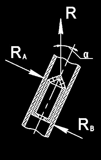
9 Fig. 1 Tubing pump. Buckling of the barrel (left) and loading scheme (right) Fig. 2 Top anchor rod pump. Buckling of the barrel (left) and loading scheme (right) Fig. 3 Distribution of forces acting on a plunger
 and loading scheme (center).")
10 Fig. 4 Bottom anchor rod pump. Straightening effect in the barrel (left) and loading scheme (center). Buckling of the barrel and rod string during pumping of highly viscous crude (right).


11 Fig. 5 Tubing with piston closed ends subject to external pressure. Fig. 6 - Straightening effect of external pressure

; straightening effect (c); diameter of the")
12 (a) (b) (c) (d) Fig. 7 Tubing with piston closed ends subject to internal pressure. Diameter of the piston ends and the rod is the same (a); buckling effect (b); straightening effect (c); diameter of the rod is smaller than diameter of the piston (d)
TUBING ANCHOR CATCHER APPLICATIONS AND OPERATION Jyothi Swaroop Samayamantula Ricky Roderick Don-Nan Pump & Supply
 TUBING ANCHOR CATCHER APPLICATIONS AND OPERATION Jyothi Swaroop Samayamantula Ricky Roderick Don-Nan Pump & Supply ABSTRACT From the selection process to installation and continued maintenance, the Tubing
Sucker Rod Pump
 Sucker Rod Pump Sucker Rod Pump Sucker Rod Pump Sucker Rod Pump 4 Sucker Rod Pump 5 Sucker Rod Pump High System Efficiency Optimization Controls Available Sucker Rod Sucker Rod Pump Assembly Tubing Anchor/
2. Write the expression for estimation of the natural frequency of free torsional vibration of a shaft. (N/D 15)
") ME 6505 DYNAMICS OF MACHINES Fifth Semester Mechanical Engineering (Regulations 2013) Unit III PART A 1. Write the mathematical expression for a free vibration system with viscous damping. (N/D 15) Viscous
ME 6505 DYNAMICS OF MACHINES Fifth Semester Mechanical Engineering (Regulations 2013) Unit III PART A 1. Write the mathematical expression for a free vibration system with viscous damping. (N/D 15) Viscous
PIPINGSOLUTIONS, INC.
 Piping Stress Analysis Where do I start? The following information will take you step-by-step through the logic of the data collection effort that should occur prior to beginning to model a piping system
Friction and Vibration Characteristics of Pneumatic Cylinder
 The 3rd International Conference on Design Engineering and Science, ICDES 214 Pilsen, Czech Republic, August 31 September 3, 214 Friction and Vibration Characteristics of Pneumatic Cylinder Yasunori WAKASAWA*
345. Fellenius, B.H., Plugging effect of opentoe pipe piles in sandy soil. Discussion. Canadian Geotechnical Journal 52(5):
:") 345. Fellenius, B.H., 215. Plugging effect of opentoe pipe piles in sandy soil. Discussion. Canadian Geotechnical Journal 52(5): 664-667.. Fellenius 215 [Canadian Geotechnical Journal 52(5) 664-667] Plugging
345. Fellenius, B.H., 215. Plugging effect of opentoe pipe piles in sandy soil. Discussion. Canadian Geotechnical Journal 52(5): 664-667.. Fellenius 215 [Canadian Geotechnical Journal 52(5) 664-667] Plugging
Analysis on natural characteristics of four-stage main transmission system in three-engine helicopter
 Article ID: 18558; Draft date: 2017-06-12 23:31 Analysis on natural characteristics of four-stage main transmission system in three-engine helicopter Yuan Chen 1, Ru-peng Zhu 2, Ye-ping Xiong 3, Guang-hu
Technical Math 2 Lab 3: Garage Door Spring 2018
 Name: Name: Name: Name: As you may have determined the problem is a broken spring (clearly shown on the left in the picture below) which needs to be replaced. I. Garage Door Basics: Common residential
A Practical Guide to Free Energy Devices
 A Practical Guide to Free Energy Devices Part PatD20: Last updated: 26th September 2006 Author: Patrick J. Kelly This patent covers a device which is claimed to have a greater output power than the input
CHAP: MACHINES Q: 1. Q: 1(Numerical) Answer Total length of crowbar =120 cm Load arm =20 cm Effort arm = =100 cm Q: 2
 Answer Total length of crowbar =120 cm Load arm =20 cm Effort arm = =100 cm Q: 2") CHAP: MACHINES Ex: 3A Q: 1 A machine is a device by which we can either overcome a large resistive force at some point by applying a small force at a convenient point and in a desired direction or by which
CHAP: MACHINES Ex: 3A Q: 1 A machine is a device by which we can either overcome a large resistive force at some point by applying a small force at a convenient point and in a desired direction or by which
Chapter 15. Inertia Forces in Reciprocating Parts
 Chapter 15 Inertia Forces in Reciprocating Parts 2 Approximate Analytical Method for Velocity & Acceleration of the Piston n = Ratio of length of ConRod to radius of crank = l/r 3 Approximate Analytical
DESIGN OF MACHINE MEMBERS - I
 R10 Set No: 1 III B.Tech. I Semester Regular and Supplementary Examinations, December - 2013 DESIGN OF MACHINE MEMBERS - I (Mechanical Engineering) Time: 3 Hours Max Marks: 75 Answer any FIVE Questions
EXAMPLES GEARS. page 1
 (EXAMPLES GEARS) EXAMPLES GEARS Example 1: Shilds p. 76 A 20 full depth spur pinion is to trans mit 1.25 kw at 850 rpm. The pinion has 18 teeth. Determine the Lewis bending stress if the module is 2 and
COMPARISON OF PRESENT-DAY LONG-STROKE SUCKER-ROD PUMPING SYSTEMS
 Műszaki Földtudományi Közlemények, 85. kötet, 1. szám (2015), pp. 191 201. COMPARISON OF PRESENT-DAY LONG-STROKE SUCKER-ROD PUMPING SYSTEMS GÁBOR TAKÁCS, PH.D. Professor, Petroleum Engineering Department
The Mechanics of Tractor Implement Performance
 The Mechanics of Tractor Implement Performance Theory and Worked Examples R.H. Macmillan CHAPTER 2 TRACTOR MECHANICS Printed from: http://www.eprints.unimelb.edu.au CONTENTS 2.1 INTRODUCTION 2.1 2.2 IDEAL
Mouse Trap Racer Scientific Investigations (Exemplar)
") Mouse Trap Racer Scientific Investigations (Exemplar) Online Resources at www.steminabox.com.au/projects This Mouse Trap Racer Classroom STEM educational kit is appropriate for Upper Primary and Secondary
Mouse Trap Racer Scientific Investigations (Exemplar) Online Resources at www.steminabox.com.au/projects This Mouse Trap Racer Classroom STEM educational kit is appropriate for Upper Primary and Secondary
Chapter 15. Inertia Forces in Reciprocating Parts
 Chapter 15 Inertia Forces in Reciprocating Parts 2 Approximate Analytical Method for Velocity and Acceleration of the Piston n = Ratio of length of ConRod to radius of crank = l/r 3 Approximate Analytical
NUMERICAL ANALYSIS OF LOAD DISTRIBUTION IN RAILWAY TRACK UNDER WHEELSET
 Journal of KONES Powertrain and Transport, Vol., No. 3 13 NUMERICAL ANALYSIS OF LOAD DISTRIBUTION IN RAILWAY TRACK UNDER WHEELSET Piotr Szurgott, Krzysztof Berny Military University of Technology Department
CLASSIFICATION OF ROLLING-ELEMENT BEARINGS
 CLASSIFICATION OF ROLLING-ELEMENT BEARINGS Ball bearings can operate at higher speed in comparison to roller bearings because they have lower friction. In particular, the balls have less viscous resistance
G.U.N.T. Gerätebau GmbH
 Equipment for Engineering Education Experiment Instructions WP950 Deformation of Straight Beams G.U.N.T. Gerätebau GmbH P.O. Box 1125 D - 22881 Barsbüttel Germany Phone+49 40 670 854-0 Fax +49 40 670 854-42
SURETRAC Construction of SURETRAC Fig. 1
 SURETRAC 1 Construction of SURETRAC SURETRAC is a new type of differential that mainly consists of two shaft hubs, two face cams, 19 cam followers, and a differential case. The shapes of the two face cams
Latest Advancements in DrillString Mechanics
 Services, Trainings, Softwares Latest Advancements in DrillString Mechanics SPE Gulf Coast Section 03/09/2016 Stephane Menand, Ph.D. stephane.menand@drillscan.com 1 DrillScan Intro Directional Drilling
HELICOPTER TAIL ROTOR ANALYSIS: EXPERIENCE IN AGUSTA WITH ADAMS
 HELICOPTER TAIL ROTOR ANALYSIS: EXPERIENCE IN AGUSTA WITH ADAMS Bianchi F., Agusta Sp.a. Via G.Agusta, 520 - Cascina Costa di Samarate,Varese - Italy - e-mail: atr@agusta.it Abstract The purpose of the
Generator Speed Control Utilizing Hydraulic Displacement Units in a Constant Pressure Grid for Mobile Electrical Systems
 Group 10 - Mobile Hydraulics Paper 10-5 199 Generator Speed Control Utilizing Hydraulic Displacement Units in a Constant Pressure Grid for Mobile Electrical Systems Thomas Dötschel, Michael Deeken, Dr.-Ing.
Prediction of Thermal Deflection at Spindle Nose-tool Holder Interface in HSM
 Prediction of Thermal Deflection at Spindle Nose-tool Holder Interface in HSM V Prabhu Raja, J Kanchana, K Ramachandra, P Radhakrishnan PSG College of Technology, Coimbatore - 641004 Abstract Loss of machining
Describe the function of a hydraulic power unit
 Chapter 7 Source of Hydraulic Power Power Units and Pumps 1 Objectives Describe the function of a hydraulic power unit and identify its primary components. Explain the purpose of a pump in a hydraulic
B.TECH III Year I Semester (R09) Regular & Supplementary Examinations November 2012 DYNAMICS OF MACHINERY
 Regular & Supplementary Examinations November 2012 DYNAMICS OF MACHINERY") 1 B.TECH III Year I Semester (R09) Regular & Supplementary Examinations November 2012 DYNAMICS OF MACHINERY (Mechanical Engineering) Time: 3 hours Max. Marks: 70 Answer any FIVE questions All questions
1 B.TECH III Year I Semester (R09) Regular & Supplementary Examinations November 2012 DYNAMICS OF MACHINERY (Mechanical Engineering) Time: 3 hours Max. Marks: 70 Answer any FIVE questions All questions
DESIGN AND ANALYSIS OF TELESCOPIC JACK
 DESIGN AND ANALYSIS OF TELESCOPIC JACK Ashish Patil 1, Sachin Wangikar 2, Sangam Patil 3, Rajashekhar M S 4 1 Assistant Professor, Mechanical Department, Shaikh College of Engineering and Technology, karnataka,
Available online at ScienceDirect. Procedia CIRP 33 (2015 )
") Available online at www.sciencedirect.com ScienceDirect Procedia CIRP 33 (2015 ) 581 586 9th CIRP Conference on Intelligent Computation in Manufacturing Engineering - CIRP ICME '14 Magnetic fluid seal
Available online at www.sciencedirect.com ScienceDirect Procedia CIRP 33 (2015 ) 581 586 9th CIRP Conference on Intelligent Computation in Manufacturing Engineering - CIRP ICME '14 Magnetic fluid seal
Dynamic Behavior Analysis of Hydraulic Power Steering Systems
 Dynamic Behavior Analysis of Hydraulic Power Steering Systems Y. TOKUMOTO * *Research & Development Center, Control Devices Development Department Research regarding dynamic modeling of hydraulic power
DHANALAKSHMI COLLEGE OF ENGINEERING
 DHANALAKSHMI COLLEGE OF ENGINEERING (Dr.VPR Nagar, Manimangalam, Tambaram) Chennai - 601 301 DEPARTMENT OF MECHANICAL ENGINEERING III YEAR MECHANICAL - VI SEMESTER ME 6601 DESIGN OF TRANSMISSION SYSTEMS
International Conference on Mechanics, Materials and Structural Engineering (ICMMSE 2016)
") International Conference on Mechanics, Materials and Structural Engineering (ICMMSE 2016) Comparison on Hysteresis Movement in Accordance with the Frictional Coefficient and Initial Angle of Clutch Diaphragm
International Conference on Mechanics, Materials and Structural Engineering (ICMMSE 2016) Comparison on Hysteresis Movement in Accordance with the Frictional Coefficient and Initial Angle of Clutch Diaphragm
A Proposed Design for a Smart Shock Absorber Using an Electro-Rheological Fluid
 A Proposed Design for a Smart Shock Absorber Using an Electro-Rheological Fluid Ahmed Nooh, Carlos Monroy, Michael Anwr Alphonse Anees and Wafik Girgis I. INTRODUCTION A. Why are shock absorbers used in
Analytical Technology for Axial Piston Pumps and Motors
 Analytical Technology for Axial Piston Pumps and Motors Technology Explanation Analytical Technology for Axial Piston Pumps and Motors SATO Naoto Abstract Axial piston pumps and motors are key products
Chapter 7: Thermal Study of Transmission Gearbox
 Chapter 7: Thermal Study of Transmission Gearbox 7.1 Introduction The main objective of this chapter is to investigate the performance of automobile transmission gearbox under the influence of load, rotational
Optimization of Scissor-jack-Damper s Parameters and Performance under the Constrain of Human Comfort
 Optimization of Scissor-jack-Damper s Parameters and Performance under the Constrain of Human Comfort *Xin ZHAO 1) and Zhuang MA 2) 1) Tongji Architectural Design(Group) Co.,Ltd.,Shanghai,China 2) Department
The University of Melbourne Engineering Mechanics
 The University of Melbourne 436-291 Engineering Mechanics Tutorial Twelve General Plane Motion, Work and Energy Part A (Introductory) 1. (Problem 6/78 from Meriam and Kraige - Dynamics) Above the earth
Development of Rattle Noise Analysis Technology for Column Type Electric Power Steering Systems
 TECHNICAL REPORT Development of Rattle Noise Analysis Technology for Column Type Electric Power Steering Systems S. NISHIMURA S. ABE The backlash adjustment mechanism for reduction gears adopted in electric
Simulating Rotary Draw Bending and Tube Hydroforming
 Abstract: Simulating Rotary Draw Bending and Tube Hydroforming Dilip K Mahanty, Narendran M. Balan Engineering Services Group, Tata Consultancy Services Tube hydroforming is currently an active area of
Reduction of Self Induced Vibration in Rotary Stirling Cycle Coolers
 Reduction of Self Induced Vibration in Rotary Stirling Cycle Coolers U. Bin-Nun FLIR Systems Inc. Boston, MA 01862 ABSTRACT Cryocooler self induced vibration is a major consideration in the design of IR
Analysis and control of vehicle steering wheel angular vibrations
 Analysis and control of vehicle steering wheel angular vibrations T. LANDREAU - V. GILLET Auto Chassis International Chassis Engineering Department Summary : The steering wheel vibration is analyzed through
Submitted by: Sr. Engineer. Sr. Product Engineer. Product Engineer. Director Power Market Sales. Approved by: Director of Engineering
 Modeling Victaulic Couplings in Piping System Stress Analysis Programs By David Hudson, BSME Gary Trinker, BSME Osama AlMasri, BSME Dan Christian, BSMC Victaulic Engineering Services Department May 2012
FRONTAL OFF SET COLLISION
 FRONTAL OFF SET COLLISION MARC1 SOLUTIONS Rudy Limpert Short Paper PCB2 2014 www.pcbrakeinc.com 1 1.0. Introduction A crash-test-on- paper is an analysis using the forward method where impact conditions
1064. Conversion and its deviation control of electric switch machine of high speed railway turnout
 164. Conversion and its deviation control of electric switch machine of high speed railway turnout Rong Chen, Ping Wang, Hao Xu 164. CONVERSION AND ITS DEVIATION CONTROL OF ELECTRIC SWITCH MACHINE OF HIGH
CONSTRUCTIVE-FUNCTIONAL ANALYSIS OF SINGLE-ROD DOUBLE-ACTING HYDRAULIC CYLINDERS
 CONTRUCTIVE-FUNCTIONAL ANALYI OF INGLE-ROD DOUBLE-ACTING HYDRAULIC CYLINDER Nicuşor Baroiu 1, Virgil Gabriel Teodor 1, Georgiana-Alexandra Costin 1 1 Dunărea de Jos University of Galaţi, Depart. of Manufacturing
210C-1 Selection materials
 7 2C- Selection materials 8 Calculation of cylinder buckling ) Be sure to calculate the cylinder buckling. 2) In the case of using a hydraulic cylinder, the stress and buckling must be considered depending
Development of Super-low Friction Torque Technology for Tapered Roller Bearing
 TECHNICAL PAPER Development of Super-low Friction Torque Technology for Tapered Roller Bearing H. MATSUYAMA H. DODORO K. OGINO H. OHSHIMA H. CHIBA K. TODA To achieve high efficiency in rear axle differentials,
Floating Oscillator based Electric Generator using Mechanical Energy Harvesting
 Floating Oscillator based Electric Generator using Mechanical Energy Harvesting V Gukan 1, T K Balasekaran 2, E ArunMozhi Devan 3, G Udhaya Kumar 4 1,2,3Student, Dept. of EEE, Valliammai Engineering College,
The CIG is designed to fit any size of API rod insert pump.
 Carbide Insert Guide (CIG) Carbide Insert Guide (CIG) The installation of the Carbide Insert Guide (CIG) will eliminate the possibility of your rod insert pump problems of broken or severely worn holdown
RHOMBUS MECHANISM WITH FLUID DAMPER
 13 th World Conference on Earthquake Engineering Vancouver, B.C., Canada August 1-6, 4 Paper No. 11 RHOMBUS MECHANISM WITH FLUID DAMPER Deh-Shiu Hsu 1, Ming-Che Hsu, and Yung-Feng Lee 3 ABSTRACT Structural
THE LONGITUDINAL VIBRATION OF COMPOSITE DRIVE SHAFT
 THE LONGITUDINAL VIBRATION OF COMPOSITE DRIVE SHAFT Tongtong Zhang, Yongsheng Li, Weibo Wang National Key Laboratory on Ship Vibration and Noise, China Ship Scientific Research Centre, Wuxi, China email:
CERTIFICATES OF COMPETENCY IN THE MERCHANT NAVY MARINE ENGINEER OFFICER
 CERTIFICATES OF COMPETENCY IN THE MERCHANT NAVY MARINE ENGINEER OFFICER EXAMINATIONS ADMINISTERED BY THE SCOTTISH QUALIFICATIONS AUTHORITY ON BEHALF OF THE MARITIME AND COASTGUARD AGENCY STCW 95 CHIEF
PIONEER RESEARCH & DEVELOPMENT GROUP
 Design and Stress Analysis of Tow Bar for Medium Sized Portable Compressors Pankaj Khannade 1, Akash Chitnis 2, Gangadhar Jagdale 3 1,2 Mechanical Department, University of Pune/ Smt. Kashibai Navale College
FEASIBILITY STYDY OF CHAIN DRIVE IN WATER HYDRAULIC ROTARY JOINT
 FEASIBILITY STYDY OF CHAIN DRIVE IN WATER HYDRAULIC ROTARY JOINT Antti MAKELA, Jouni MATTILA, Mikko SIUKO, Matti VILENIUS Institute of Hydraulics and Automation, Tampere University of Technology P.O.Box
Available online at ScienceDirect. Procedia Engineering 68 (2013 ) 70 76
 70 76") Available online at www.sciencedirect.com ScienceDirect Procedia Engineering 68 (2013 ) 70 76 Malaysian International Tribology Conference 2013 (MITC2013) The Effects of Oil Supply Pressure at Different
Available online at www.sciencedirect.com ScienceDirect Procedia Engineering 68 (2013 ) 70 76 Malaysian International Tribology Conference 2013 (MITC2013) The Effects of Oil Supply Pressure at Different
ANALYSIS OF GEAR QUALITY CRITERIA AND PERFORMANCE OF CURVED FACE WIDTH SPUR GEARS
 8 FASCICLE VIII, 8 (XIV), ISSN 11-459 Paper presented at Bucharest, Romania ANALYSIS OF GEAR QUALITY CRITERIA AND PERFORMANCE OF CURVED FACE WIDTH SPUR GEARS Laurentia ANDREI 1), Gabriel ANDREI 1) T, Douglas
Section 4 WHAT MAKES CHARGE MOVE IN A CIRCUIT?
 Section 4 WHAT MAKES CHARGE MOVE IN A CIRCUIT? INTRODUCTION Why does capacitor charging stop even though a battery is still trying to make charge move? What makes charge move during capacitor discharging
Seismic Capacity Test of Overhead Crane under Horizontal and Vertical Excitation - Element Model Test Results on Nonlinear Response Behavior-
 2th International Conference on Structural Mechanics in Reactor Technology (SMiRT 2) Espoo, Finland, August 9-14, 29 SMiRT 2-Division, Paper Seismic Capacity Test of Overhead Crane under Horizontal and
Analysis of Torsional Vibration in Elliptical Gears
 The The rd rd International Conference on on Design Engineering and Science, ICDES Pilsen, Czech Pilsen, Republic, Czech August Republic, September -, Analysis of Torsional Vibration in Elliptical Gears
This document is a preview generated by EVS
 TECHNICAL SPECIFICATION ISO/TS 13725 Second edition 2016-06-01 Hydraulic fluid power Method for evaluating the buckling load of a hydraulic cylinder Transmissions hydrauliques Méthode d évaluation du flambage
Lecture 25 HYDRAULIC CIRCUIT DESIGN AND ANALYSIS [CONTINUED]
![Lecture 25 HYDRAULIC CIRCUIT DESIGN AND ANALYSIS [CONTINUED]](/thumbs/92/110490177.jpg "Lecture 25 HYDRAULIC CIRCUIT DESIGN AND ANALYSIS [CONTINUED]") Lecture 5 HYDRAULIC CIRCUIT DESIGN AND ANALYSIS [CONTINUED] 1.1 Circuit for Fast Approach and Slow Die Closing A machine intended for high volume production has a high piston velocity. If not controlled,
Lecture 5 HYDRAULIC CIRCUIT DESIGN AND ANALYSIS [CONTINUED] 1.1 Circuit for Fast Approach and Slow Die Closing A machine intended for high volume production has a high piston velocity. If not controlled,
Heat Engines Lab 12 SAFETY
 HB 1-05-09 Heat Engines 1 Lab 12 1 i Heat Engines Lab 12 Equipment SWS, 600 ml pyrex beaker with handle for ice water, 350 ml pyrex beaker with handle for boiling water, 11x14x3 in tray, pressure sensor,
INFLUENCE OF TEMPERATURE ON THE PERFORMANCE TOOTHED BELTS BINDER MAGNETIC
 INFLUENCE OF TEMPERATURE ON THE PERFORMANCE TOOTHED BELTS BINDER MAGNETIC Merghache Sidi Mohammed, Phd Student Ghernaout Med El-Amine, Doctor in industrial automation University of Tlemcen, ETAP laboratory,
Design Evaluation of Fuel Tank & Chassis Frame for Rear Impact of Toyota Yaris
 International Research Journal of Engineering and Technology (IRJET) e-issn: 2395-0056 Volume: 03 Issue: 05 May-2016 p-issn: 2395-0072 www.irjet.net Design Evaluation of Fuel Tank & Chassis Frame for Rear
The Life of a Lifter, Part 2
 Basics Series: The Life of a Lifter, Part 2 -Greg McConiga Last time we looked at some complicated dynamics and compared flats to rollers. Now for the hands-on. 6 FEATURE This off-the-shelf hydraulic lifter
R10 Set No: 1 ''' ' '' '' '' Code No: R31033
 R10 Set No: 1 III B.Tech. I Semester Regular and Supplementary Examinations, December - 2013 DYNAMICS OF MACHINERY (Common to Mechanical Engineering and Automobile Engineering) Time: 3 Hours Max Marks:
A COMPARISON OF THE PERFORMANCE OF LINEAR ACTUATOR VERSUS WALKING BEAM PUMPING SYSTEMS Thomas Beck Ronald Peterson Unico, Inc.
 A COMPARISON OF THE PERFORMANCE OF LINEAR ACTUATOR VERSUS WALKING BEAM PUMPING SYSTEMS Thomas Beck Ronald Peterson Unico, Inc. ABSTRACT Rod pumping units have historically used a crank-driven walking beam
Bandmill Strain System Response
 Bandmill Strain System Response Bruce Lehmann, Ph.D., P.Eng, Sr. Engineer, Thin Kerf Technologies Inc. The responsiveness of the strain system of a bandmill is a critical factor for bandsaw performance
Development of analytical process to reduce side load in strut-type suspension
 Journal of Mechanical Science and Technology 24 (21) 351~356 www.springerlink.com/content/1738-494x DOI 1.7/s1226-9-113-z Development of analytical process to reduce side load in strut-type suspension
IJESRT. Scientific Journal Impact Factor: (ISRA), Impact Factor: METHODOLOGY Design Parameter [250]
![IJESRT. Scientific Journal Impact Factor: (ISRA), Impact Factor: METHODOLOGY Design Parameter [250]](/thumbs/93/112194125.jpg "IJESRT. Scientific Journal Impact Factor: (ISRA), Impact Factor: METHODOLOGY Design Parameter [250]") IJESRT INTERNATIONAL JOURNAL OF ENGINEERING SCIENCES & RESEARCH TECHNOLOGY DESIGN AND ANALYSIS OF COMPOSITE LEAF SPRING FOR LIGHT COMMERCIAL VEHICLE (TATA ACE) Miss. Gulshad Karim Pathan*, Prof. R.K.Kawade,
IJESRT INTERNATIONAL JOURNAL OF ENGINEERING SCIENCES & RESEARCH TECHNOLOGY DESIGN AND ANALYSIS OF COMPOSITE LEAF SPRING FOR LIGHT COMMERCIAL VEHICLE (TATA ACE) Miss. Gulshad Karim Pathan*, Prof. R.K.Kawade,
Engineering Analysis. Team: 5 Guys Engineering + 1 Nathan Bessette, Rahul Bhatia, Andrew Cass, Glen Stewart
 Engineering Analysis Presentation ME 4182 Team: 5 Guys Engineering + 1 Nathan Bessette, Rahul Bhatia, Andrew Cass, Zeeshan Saiyed, Glen Stewart YJ JChok Automatic Whiteboard Wiper Last Time Last Time Layout
Test Rig Design for Measurement of Shock Absorber Characteristics
 Test Rig Design for Measurement of Shock Absorber Characteristics H. R. Sapramer Dr. G. D. Acharya Mechanical Engineering Department Principal Sir Bhavsinhaji Polytechnic Institute Atmiya Institute of
High Speed Gears - New Developments
 High Speed Gears - New Developments by T. Oeeg Contents: 1. Introduction 2. Back to Back Test Bed 3. Radial Tilting Pad Bearings 3.1 Design 3.2 Test Results 3.3 Deformation Analysis 4. Axial Tilting Pad
Active magnetic inertia latch for hard disk drives
 Microsyst Technol (2011) 17:127 132 DOI 10.1007/s00542-010-1168-8 TECHNICAL PAPER Active magnetic inertia latch for hard disk drives Bu Hyun Shin Kyung-Ho Kim Seung-Yop Lee Received: 2 August 2010 / Accepted:
Static Structural and Thermal Analysis of Aluminum Alloy Piston For Design Optimization Using FEA Kashyap Vyas 1 Milan Pandya 2
 IJSRD - International Journal for Scientific Research & Development Vol. 2, Issue 03, 2014 ISSN (online): 2321-0613 Static Structural and Thermal Analysis of Aluminum Alloy Piston For Design Optimization
VEHICLE ANTI-ROLL BAR ANALYZED USING FEA TOOL ANSYS
 VEHICLE ANTI-ROLL BAR ANALYZED USING FEA TOOL ANSYS P. M. Bora 1, Dr. P. K. Sharma 2 1 M. Tech. Student,NIIST, Bhopal(India) 2 Professor & HOD,NIIST, Bhopal(India) ABSTRACT The aim of this paper is to
Newton s 2 nd Law Activity
 Newton s 2 nd Law Activity Purpose Students will begin exploring the reason the tension of a string connecting a hanging mass to an object will be different depending on whether the object is stationary
Chapter 2 Analysis on Lock Problem in Frontal Collision for Mini Vehicle
 Chapter 2 Analysis on Lock Problem in Frontal Collision for Mini Vehicle Ce Song, Hong Zang and Jingru Bao Abstract To study the lock problem in the frontal collision test on a kind of mini vehicle s sliding
Test rig for rod seals contact pressure measurement
 Tribology and Design 107 Test rig for rod seals contact pressure measurement G. Belforte 1, M. Conte 2, L. Mazza 1, T. Raparelli 1 & C. Visconte 1 1 Department of Mechanics, Politecnico di Torino, Italy
Finite Element Analysis of Clutch Piston Seal
 Finite Element Analysis of Clutch Piston Seal T. OYA * F. KASAHARA * *Research & Development Center Tribology Research Department Three-dimensional finite element analysis was used to simulate deformation
The Effect of Friction between a Cylindrical Guide and Magnetic Tape on Lateral Tape Motion
 The Effect of Friction between a Cylindrical Guide and Magnetic Tape on Lateral Tape Motion B. and F. E. Talke Center for Magnetic Recording Research University of California, San Diego 95 Gilman Drive
Dynamic characteristics of railway concrete sleepers using impact excitation techniques and model analysis
 Dynamic characteristics of railway concrete sleepers using impact excitation techniques and model analysis Akira Aikawa *, Fumihiro Urakawa *, Kazuhisa Abe **, Akira Namura * * Railway Technical Research
MIKLOS Cristina Carmen, MIKLOS Imre Zsolt UNIVERSITY POLITEHNICA TIMISOARA FACULTY OF ENGINEERING HUNEDOARA ABSTRACT:
 1 2 THEORETICAL ASPECTS ABOUT THE ACTUAL RESEARCH CONCERNING THE PHYSICAL AND MATHEMATICAL MODELING CATENARY SUSPENSION AND PANTOGRAPH IN ELECTRIC RAILWAY TRACTION MIKLOS Cristina Carmen, MIKLOS Imre Zsolt
BLAST CAPACITY ASSESSMENT AND TESTING A-60 OFFSHORE FIRE DOOR
 BLAST CAPACITY ASSESSMENT AND TESTING Final Report December 11, 2008 A-60 OFFSHORE FIRE DOOR Prepared for: JRJ Alum Fab, Inc. Prepared by: Travis J. Holland Michael J. Lowak John R. Montoya BakerRisk Project
White paper: Originally published in ISA InTech Magazine Page 1
 Page 1 Improving Differential Pressure Diaphragm Seal System Performance and Installed Cost Tuned-Systems ; Deliver the Best Practice Diaphragm Seal Installation To Compensate Errors Caused by Temperature
Technical Report Con Rod Length, Stroke, Piston Pin Offset, Piston Motion and Dwell in the Lotus-Ford Twin Cam Engine. T. L. Duell.
 Technical Report - 1 Con Rod Length, Stroke, Piston Pin Offset, Piston Motion and Dwell in the Lotus-Ford Twin Cam Engine by T. L. Duell May 24 Terry Duell consulting 19 Rylandes Drive, Gladstone Park
Optimization Design of the Structure of the Manual Swing-out Luggage Compartment Door of Passenger Cars
 Research Journal of Applied Sciences, Engineering and Technology 6(7): 1267-1271, 2013 ISSN: 2040-7459; e-issn: 2040-7467 Maxwell Scientific Organization, 2013 Submitted: November 08, 2012 Accepted: January
ANALYSIS OF REVERSE FLOW IN LOW-RISE INVERTED U-TUBE STEAM GENERATOR OF PWR PACTEL FACILITY
 ANALYSIS OF REVERSE FLOW IN LOW-RISE INVERTED U-TUBE STEAM GENERATOR OF PWR PACTEL FACILITY Kauppinen, O-P., Riikonen, V., Kouhia, V., Hyvärinen, J. LUT School of Energy Systems / Nuclear Engineering Lappeenranta
APPLICATION OF A NEW TYPE OF AERODYNAMIC TILTING PAD JOURNAL BEARING IN POWER GYROSCOPE
 Colloquium DYNAMICS OF MACHINES 2012 Prague, February 7 8, 2011 CzechNC APPLICATION OF A NEW TYPE OF AERODYNAMIC TILTING PAD JOURNAL BEARING IN POWER GYROSCOPE Jiří Šimek Abstract: New type of aerodynamic
(12) Patent Application Publication (10) Pub. No.: US 2007/ A1
 Patent Application Publication (10) Pub. No.: US 2007/ A1") (19) United States US 2007.0099.746A1 (12) Patent Application Publication (10) Pub. No.: US 2007/0099746A1 Hahlbeck (43) Pub. Date: MaV 3, 2007 9 (54) SELF ALIGNING GEAR SET Publication Classification
(19) United States US 2007.0099.746A1 (12) Patent Application Publication (10) Pub. No.: US 2007/0099746A1 Hahlbeck (43) Pub. Date: MaV 3, 2007 9 (54) SELF ALIGNING GEAR SET Publication Classification
Benefits of the Gas Bailer
 The GAS BAILER VALVE Prevent GAS LOCK & Reduce Gas Interference in SUCKER ROD PUMPS Increase Production & Extend Pump Life Threads onto bottom of Traveling Valve Benefits of the Gas Bailer Increase pump
RENTAL TOOL SERVICES. Megaton Impact Tools
 Megaton Impact Tools Upper Connector Megaton Impact Tools optimize your drilling operations. Drive Mandrel Female Spline Bearing Female Spline New-Generation Drilling Tools Megaton Drilling Jar Frees the
PREDICTION OF PISTON SLAP OF IC ENGINE USING FEA BY VARYING GAS PRESSURE
 PREDICTION OF PISTON SLAP OF IC ENGINE USING FEA BY VARYING GAS PRESSURE V. S. Konnur Department of Mechanical Engineering, BLDEA s Engineering College, Bijapur, Karnataka, (India) ABSTRACT The automotive
Design And Analysis Of Two Wheeler Front Wheel Under Critical Load Conditions
 Design And Analysis Of Two Wheeler Front Wheel Under Critical Load Conditions Tejas Mulay 1, Harish Sonawane 1, Prof. P. Baskar 2 1 M. Tech. (Automotive Engineering) students, SMBS, VIT University, Vellore,
AGN 076 Alternator Bearings
 Application Guidance Notes: Technical Information from Cummins Generator Technologies AGN 076 Alternator Bearings BEARING TYPES In the design of STAMFORD and AvK alternators, the expected types of rotor
AXLE HOUSING AND UNITIZE BEARING PACK SET MODAL CHARACTERISATION
 F2004F461 AXLE HOUSING AND UNITIZE BEARING PACK SET MODAL CHARACTERISATION 1 Badiola, Virginia*, 2 Pintor, Jesús María, 3 Gainza, Gorka 1 Dana Equipamientos S.A., España, 2 Universidad Pública de Navarra,
LEAD SCREWS 101 A BASIC GUIDE TO IMPLEMENTING A LEAD SCREW ASSEMBLY FOR ANY DESIGN
 LEAD SCREWS 101 A BASIC GUIDE TO IMPLEMENTING A LEAD SCREW ASSEMBLY FOR ANY DESIGN Released by: Keith Knight Kerk Products Division Haydon Kerk Motion Solutions Lead Screws 101: A Basic Guide to Implementing
Counterbalance Transportation System
 Counterbalance Transportation System Introduction The idea of our robot came from a Sample Return Rover 1 that was created by NASA. The Rough terrain mobility of a mobile robot could easily be increased
Influence of Internal Combustion Engine Parameters on Gas Leakage through the Piston Rings Area
 Modern Mechanical Engineering, 2017, 7, 27-33 http://www.scirp.org/journal/mme ISSN Online: 2164-0181 ISSN Print: 2164-0165 Influence of Internal Combustion Engine Parameters on Gas Leakage through the
Application of ABAQUS to Analyzing Shrink Fitting Process of Semi Built-up Type Marine Engine Crankshaft
 Application of ABAQUS to Analyzing Shrink Fitting Process of Semi Built-up Type Marine Engine Crankshaft Jae-Cheol Kim, Dong-Kwon Kim, Young-Duk Kim, and Dong-Young Kim System Technology Research Team,