The X, Y, and Z of Circuit Breaker Control
|
|
|
- Patience Haynes
- 5 years ago
- Views:
Transcription

1 The X, Y, and Z of Circuit Breaker Control BRENT L. CARPER, P.E. Principal Engineer Presented at the 35th Annual Hands-On Relay School March 12-16, 2018
2 Agenda Importance of Breaker Control The IEEE C37.11 Standard Breaker control circuit 12 step program for breaker closing Trip coil monitoring Seal-in Anti-pump Demonstrations
 Electrical forces Magnetic forces from fault currents (e.g. 40,000 Amps)")
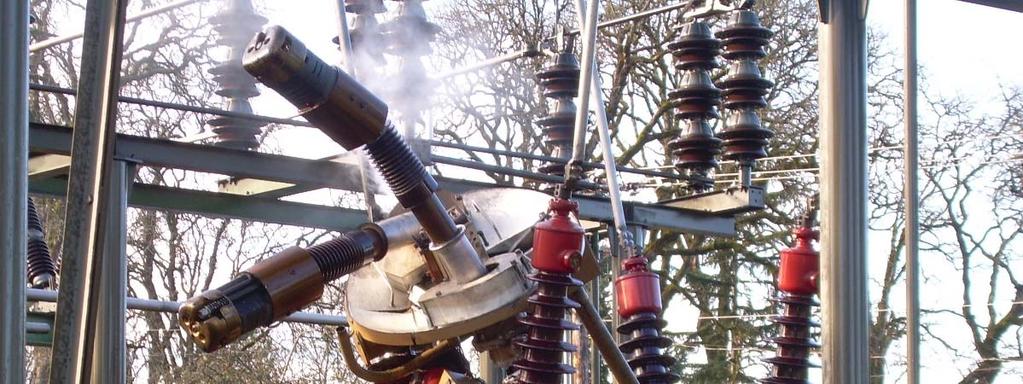
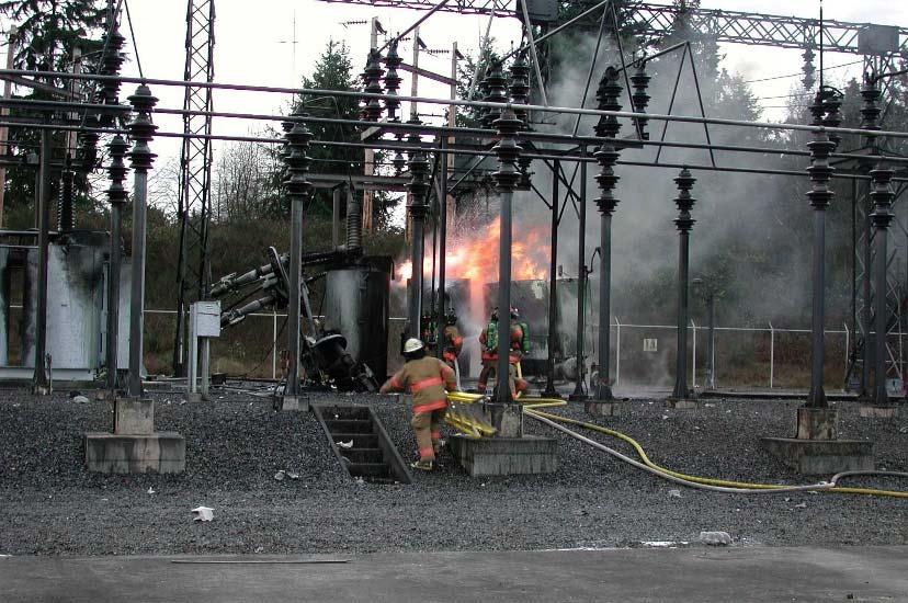
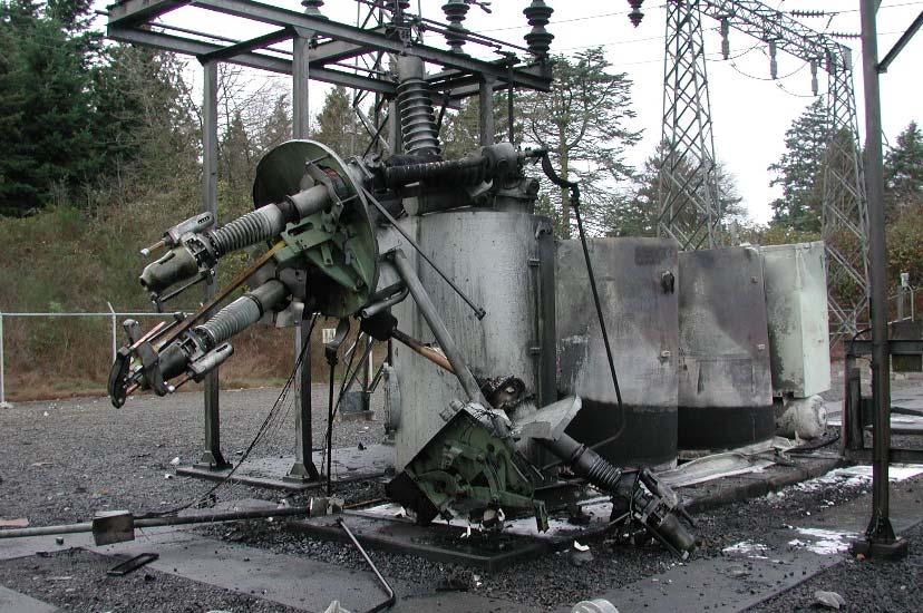
3 The importance of breaker control Mechanical forces Acceleration-Travel-Deceleration Very fast from one closed to open, or open to closed (e.g. 3 cycles = seconds) Electrical forces Magnetic forces from fault currents (e.g. 40,000 Amps)

4 The importance of breaker control

5 The importance of breaker control
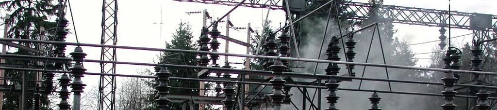
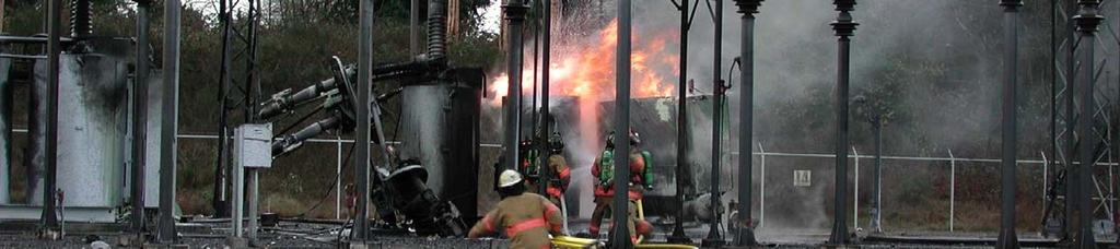

6 The importance of breaker control

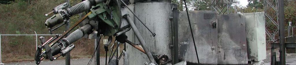
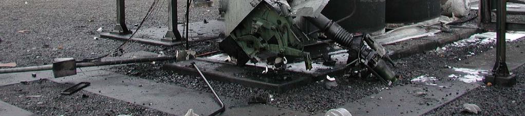
7 The importance of breaker control
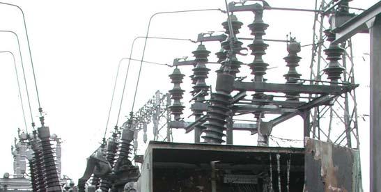
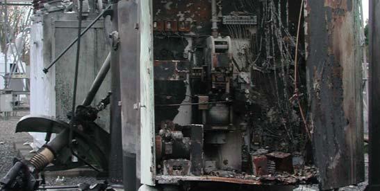
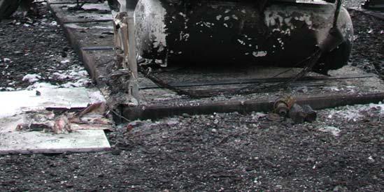
8 The importance of breaker control
9 IEEE C37.11
10 IEEE C37.11 IEEE Standard Requirements for Electrical Control for AC High-Voltage Circuit Breakers Rated on a Symmetrical Current Basis Contains 5 Sections 1. Overview 2. References 3. Functional Requirements 4. Devices and Auxiliaries 5. Wiring Requirements
11 IEEE C37.11 Section 5: Wiring Requirements
12 C37.11 Part 5: Wiring Requirements
13 Section 5: Wiring Requirements
14 Section 5: Wiring Requirements

15 Section 5: Wiring Requirements
16 Section 5: Wiring Requirements
17 Circuit Breaker Controls
18 The 12 Step Program for Successful Breaker Closing
19 1. Normal state Breaker is open Mechanism is not charged Control power is not applied
20 2. Apply Closing Power Motor (88) runs to charge mechanism
21 3. Mechanism charged All 63 contacts change state Motor stops running
22 4. Apply Control Power Breaker is still open Green light is on
23 5. Close Command Energizes 52X relay
24 6. 52X Relay Operates All 52X contacts change state Energizes 52CC breaker closing coil 52CC releases energy to close the breaker
25 7. Breaker Closing Breaker begins to close All 52b contacts open
26 8. Breaker Closed All 52a contacts close Energizes 52Y relay Red light is on (trip coil monitoring)
27 Sidebar: Trip Coil Monitoring Q: Why does this circuit not trip the breaker? It is a complete circuit. A: Circuit is a voltage divider (two impedances in series), and the Red Light is a much larger impedance than the Trip Coil. Example: 48 Vdc control circuit Red Lamp = 1200 ohms; Trip Coil = 3 ohms Voltage across the Red Light = 48 x 1200 / (1200+3) = V Voltage across the Trip Coil = 48 x 3 / (1200+3) = 0.12 V Power absorbed by the Red Light = / 1200 = 1.9 Watts Power absorbed by the Trip Coil = / 3 = Watts Current in the circuit = 48 / (1200+3) = A Current through the trip coil during a trip = 48 / 3 = 16 A
28 Sidebar: Trip Coil and 52a Contact Q: Why does the trip coil always have a 52a contact in series with it? A: 3 Reasons: 1. Block energizing the coil when the breaker is already open. 2. Trip coil passes a lot of current (e.g. 16 Amps in the previous example; often more). 52a is a heavy-duty contact that is rated to interrupt that current so that the tripping devices (relays) do not have to. 3. Trip coil is not rated for continuous current. It needs to be de-energized as soon as possible after it has done its job to trip the breaker. Q: Why use a coil that isn t rated for continuous use? A: Speed. And... Because we are intentionally over-dutying the trip coil, trip coil monitoring is critically important.
29 9. 52Y Relay Operates All 52Y contacts change state 52X relay drops out
30 10. 52X Relay Resets All 52X contacts change state back to normal 52CC drops out
31 11. Close Command is Released 52Y relay drops out
32 12. 52Y Relay Resets All 52Y contacts change state back to normal Closing cycle complete
33 Breaker Tripping
34 Breaker Trip
35 Breaker Trip Trip command
36 Breaker Trip Trip command Energizes 52TC breaker trip coil Breaker begins to open
37 Breaker Trip Trip command Energizes 52TC breaker trip coil Breaker begins to open 52a contacts open
38 Breaker Trip Trip command Energizes 52TC breaker trip coil Breaker begins to open 52a contacts open Breaker fully open 52b contacts close
39 Breaker Trip Trip command Energizes 52TC breaker trip coil Breaker begins to open 52a contacts open Breaker fully open 52b contacts close Trip command is released
40 IEEE C37.11 Section 3: Functional Requirements
41 C37.11 Part 3: Functional Requirements 3a) Seal-in for close 3b) Anti-pump 3c) Reset after an incomplete close 3d) No close operation if already closed 3e) Block close for low stored energy 3f) Low gas block trip and close 3g) Low gas alarm 3h) Block close if tripped free 3i) Pressure nuisance alarms 3j) Pole disagreement tripping
42 IEEE C37.11 Section 3e
43 3e) Block close for low stored energy Breaker is open
44 3e) Block close for low stored energy Breaker is open Low stored energy 63 contact in the close control circuit accomplishes the 3e) requirements
45 IEEE C37.11 Section 3d
46 3d) No close if already closed Breaker is closed 52b contact in the close control circuit accomplishes the 3d) requirements Just like the 52a prevents reenergizing the trip coil if the breaker is already open Demonstration
47 IEEE C37.11 Section 3a
48 3a) Seal-in for close Breaker is open Step 5. 52X relay is energized Step 6. 52X relay operates What happens if the close command drops out before the breaker completes its close cycle? Doesn t matter. 52X is sealed-in. Demonstration
49 IEEE C37.11 Section 3c
50 3c) Reset after an incomplete close 52X seal-in lasts forever Must fully reset if control power is cycled
51 3c) Reset after an incomplete close 52X seal-in lasts forever Must fully reset if control power is cycled 52X drops out and contacts return to normal
52 3c) Reset after an incomplete close 52X seal-in lasts forever Must fully reset if control power is cycled 52X drops out and contacts return to normal Restoring control power does not cause 52X to pick up and does not result in the breaker closing; all devices remain reset Demonstration
53 IEEE C37.11 Section 3b
54 3b) Anti-pumping Breaker is open Step 7. Closing coil operates
55 3b) Anti-pumping 52b contact opens Breaker closes 52a contact closes
56 3b) Anti-pumping 52b contact opens Breaker closes 52a contact closes 52Y relay energizes 52Y contacts change state
57 3b) Anti-pumping 52b contact opens Breaker closes 52a contact closes 52Y relay energizes 52Y contacts change state 52X relay drops out 52CC drops out But what if closing in to a fault?
58 3b) Anti-pumping Breaker closes... Into a fault!
59 3b) Anti-pumping Breaker closes... Into a fault! Same 52Y energize, 52X drop out, 52CC drop out
60 3b) Anti-pumping Breaker closes... Into a fault! Same 52Y energize, 52X drop out, 52CC drop out Relay trip to the breaker
61 3b) Anti-pumping Breaker closes... Into a fault! Same 52Y energize, 52X drop out, 52CC drop out Relay trip to the breaker Breaker opens Even though there is still a close command, the breaker will not close. Demonstration

62 3b) Anti-pumping

63 3b) Anti-pumping
64 Summary
65 Summary Breaker terminal block numbers Specified in IEEE C37.11 Can vary depending on type of breaker and AC/DC Trip Coil Monitoring (TCM) Required in the standard for most breaker types Good practice for other devices as well (86 lockout relays), especially when the coil is not rated for continuous duty IEEE C37.11 Primarily applies to circuit breaker manufacturers But... it is important for engineers and techs and wiremen to understand X/Y schemes Maintenance, testing, and troubleshooting operations
66 Summary X/Y Schemes Protect the breaker and are required by IEEE C37.11 Schematics can be confusing; work through one action/reaction one step at a time. If you can sequence an X/Y scheme, you can do any schematic! 52X relay provides Seal-In for closing Remember this if troubleshooting a stuck breaker Not all breaker types need a 52X relay 52Y relay provides Anti-Pump protection The breaker s 52Y relay can be fooled by chattering closing relays (25, 27/59, 79) or worn contacts on closing devices (relays, 01, SCADA)
67 BRENT L. CARPER, P.E. Principal Engineer office: cell: AC-Eng.com
Circuit breaker interlocking and operation requirements SIEMENS
 Circuit breaker interlocking and operation requirements SIEMENS When manufacturers and specifiers discuss circuit breaker operational and interlocking requirements, several terms are used repeatedly. Despite
BREAKER FAILURE PROTECTION
 29 th Annual HANDS-ON RELAY SCHOOL March 12-16, 2012 BREAKER FAILURE PROTECTION Brent Carper, PE Protection & Integration Engineer brent.c@relayapplication.com OUTLINE Protection System Failures and Breaker
1. Take the cover off the relay, taking care to not shake or jar the relay or other relays around it.
 RC SCOPE This test procedure covers the testing and maintenance of Westinghouse RC relays. The Westinghouse Protective Relay Division was purchased by ABB, and new relays carry the ABB label. Refer to
Beware of Ghost Voltage
 Beware of Ghost Voltage This article serves two purposes. First, it is an article for technicians who have heard of the dreaded ghost voltage but never understood why it happens. Second, for my own apprentices
Specification Guide. for RMVAC. Direct Replacement. AC Medium Voltage. Circuit Breakers
 Specification Guide for RMVAC Direct Replacement AC Medium Voltage Circuit Breakers Table of Contents 1.0 General Work Scope... 3 2.0 Standards... 3 3.0 Supplier Qualifications... 4 4.0 Circuit Breaker
Medium Voltage Standby non-paralleling Control GUIDE FORM SPECIFICATION
 Medium Voltage Standby non-paralleling Control 1. GENERAL GUIDE FORM SPECIFICATION A. The requirements of the contract, Division 1, and part 16 apply to work in this section. 1.01 SECTIONS INCLUDE A. Medium
COLDWATER LAKE FACILITIES DUPLEX PUMP STATION
 COLDWATER LAKE FACILITIES DUPLEX PUMP STATION TROUBLESHOOTING GUIDE REFERENCE: Operation Instructions Ladder Schematic Diagrams SCOPE The following troubleshooting guide has been specifically prepared
Flotection: Building Main Shutoff System
 Flotection: Building Main Shutoff System Overview of System Retail stores have a requirement for night time monitoring of the Domestic Water Supply. When flow is detected, during the hours the store is
Using new Magnetically Actuated Vacuum Interrupter technology for safe and reliable medium voltage circuit breaker switching in mines
 Using new Magnetically Actuated Vacuum Interrupter technology for safe and reliable medium voltage circuit breaker switching in mines Abstract: The development of the magnetically actuated vacuum interrupter
Close-Open (Short-Circuit) Time Results Interpretation
 Time Results Interpretation") Application Note Close-Open (Short-Circuit) Time Results Interpretation Close-Open (C-O, trip-free) cycles simulate closing on a short circuit. In the actual event, the breaker closes first, then the protection
Application Note Close-Open (Short-Circuit) Time Results Interpretation Close-Open (C-O, trip-free) cycles simulate closing on a short circuit. In the actual event, the breaker closes first, then the protection
Horizontal Circuit Switchers
 > Transformer Protection > CIRCUIT SWITCHERS C A T A L O G B U L L E T I N General Application Southern States Types CSH and CSH-B Horizontal Circuit Switchers provide an economical, versatile, space saving
ABB Automation, Inc. Substation Automation & Protection Division Coral Springs, FL Allentown, PA
 ABB Automation, Inc. Substation Automation & Protection Division Coral Springs, FL Allentown, PA Instruction Leaflet I.L. 41-661.1B Effective: June 1997 Supersedes I.L. 41-661.1A, Dated February 1994 Type
ELECTRIC SCHEMATICS LS1 LS2. "1532ES / 1932ES" Service & Parts Manual - ANSI Specifications March 2008 Page 5-9 ART_2236 ART_2243
 ELECTRIC SCHEMATICS NOTES: (Unless otherwise specified). Switch S BASE/PLATFORM makes contact from the CENTER to the LEFT position when placed in BASE.. Switch S UP/DOWN makes contact from the CENTER to
MOLDED CASE CIRCUIT BREAKER BASICS. David Castor, P.E.
 MOLDED CASE CIRCUIT BREAKER BASICS David Castor, P.E. History of MCCBs 1904 - Cutter Manufacturing Co., Philadelphia, produces circuit breakers. They called it the Inverse Time Element breaker, or I-T-E
Horizontal Circuit Switchers
 > Transformer Protection > CIRCUIT SWITCHERS C A T A L O G B U L L E T I N General Application Southern States Types CSH and CSH-B Horizontal Circuit Switchers provide an economical, versatile, space saving
J1 Plug Pin Identification
 D5 D D D D5 D ART_ J D D0 R R R R TB 0 D D D D D D J Plug Pin Identification PIN # WIRE # SIGNAL FUNCTION 0 INPUT Drive Reverse INPUT Drive Forward OUTPUT Brake, Decel Valve signal INPUT Steer Left 5 OUTPUT
J1 Plug Pin Identification
 D5 D8 D7 D4 D5 D ART_8 J 4 8 D D0 7 R R R R4 TB 80 D D D D4 D D J Plug Pin Identification PIN # WIRE # SIGNAL FUNCTION 0 INPUT Drive Reverse INPUT Drive Forward OUTPUT Brake, Decel Valve signal 4 8 INPUT
Tattletale Annunciators and Magnetic Switches
 Tattletale Annunciators and Magnetic Switches Tattletale annunciators and magnetic switches are the nerve centers that translate Swichgage contact operations into decisions and operate the alarm or shutdown
Module 2 CONTROL SYSTEM COMPONENTS. Lecture - 4 RELAYS
 1 Module 2 CONTROL SYSTEM COMPONENTS Lecture - 4 RELAYS Shameer A Koya Introduction Relays are generally used to accept information from some form of sensing device and convert it into proper power level,
2000 Cooper Bussmann, Inc. Page 1 of 9 10/04/00
 DO YOU KNOW THE FACTS ABOUT SINGLE-POLE INTERRUPTING RATINGS? YOU MAY BE IN TROUBLE! Typical plant electrical systems use three-phase distribution schemes. As an industry practice, short-circuit calculations
Trip Circuit and Trip coil supervision Relay
 PROTECTION Trip Circuit and Trip coil supervision Relay Type VAX Customer Benefits: Trip circuit and trip coil supervision relay Choice of pre closing and post-closing supervision Simple and robust construction
University of Houston Master Construction Specifications Insert Project Name SECTION ELECTRONIC VARIABLE SPEED DRIVES PART 1 - GENERAL
 SECTION 23 04 10 ELECTRONIC VARIABLE SPEED DRIVES PART 1 - GENERAL 1.1 RELATED DOCUMENTS: A. The Conditions of the Contract and applicable requirements of Division 1, "General Requirements", and Section
1333 (SERIES B & C) TROUBLESHOOTING GUIDE
 TROUBLESHOOTING GUIDE") 1333 (SERIES B & C) TROUBLESHOOTING GUIDE Preventive Maintenance: Problems with Your Drive? Bulletin 1333 is convection or fan cooled by air flowing through the heat sink slots. The slots must never be
1333 (SERIES B & C) TROUBLESHOOTING GUIDE Preventive Maintenance: Problems with Your Drive? Bulletin 1333 is convection or fan cooled by air flowing through the heat sink slots. The slots must never be
Installation and Maintenance Instructions. World Leader in Modular Torque Limiters. PTM-4 Load Monitor
 World Leader in Modular Torque Limiters Installation and Maintenance Instructions PTM-4 Load Monitor 1304 Twin Oaks Street Wichita Falls, Texas 76302 (940) 723-7800 Fax: (940) 723-7888 E-mail: sales@brunelcorp.com
2015 EDITION SUBMERSIBLE MOTORS AIM MANUAL. APPLICATION INSTALLATION MAINTENANCE 60 Hz, Single-Phase and Three-Phase Motors. franklinwater.
 0 EDITION AIM MANUAL SUBMERSIBLE MORS APPLICATION INSTALLATION 60 Hz, Single-Phase and Three-Phase Motors franklinwater.com All Motors System Troubleshooting Motor Does Not Start A. No power or incorrect
Transformer Protection
 Transformer Protection Course No: E01-006 Credit: 1 PDH Andre LeBleu, P.E. Continuing Education and Development, Inc. 9 Greyridge Farm Court Stony Point, NY 10980 P: (877) 322-5800 F: (877) 322-4774 info@cedengineering.com
J1 Plug Pin Identification
 D D8 D D D D ART_8 J 8 D D0 R R R R TB 80 D D D D D D J Plug Pin Identification PIN # WIRE # SIGNAL FUNCTION 0 INPUT Drive Reverse INPUT Drive Forward OUTPUT Brake, Decel Valve signal 8 INPUT Steer Left
SECTION MOTOR CONTROL
 SECTION 26 24 19 MOTOR CONTROL PART 1 - GENERAL 1.1 SECTION INCLUDES A. Manual motor starters B. Magnetic motor starters C. Combination magnetic motor starters D. Solid-state reduced voltage motor starters
Foreword
 Foreword Content 1. Summary 2. Safety instruction Safety Symbol Indication Attention Static discharge sensitive Electric shock Dangerous Indicate risk of serious injury or death or seriously damage the
 8803214-8803999 DIODE BOARD The diode board is located inside the lower control box. D15 D8 D7 D14 D5 D13 ART_2181 J1 14 8 D9 D10 7 1 R2 R1 R3 R4 TB1 8601 D11 D3 D12 D4 D1 D2 J1 Plug Pin Identification
 DIODE BOARD The diode board is located inside the lower control box. D15 D8 D7 D14 D5 D13 ART_2181 J1 14 8 D9 D10 7 1 R2 R1 R3 R4 TB1 8601 D11 D3 D12 D4 D1 D2 J1 Plug Pin Identification PIN # WIRE # SIGNAL
Application Note. Common Bussing AC Drives. For 650 and 690+ series drives APP-AC-03
 Application Common Bussing AC Drives APP-AC-03 For 650 and 690+ series drives APP-AC-03 2004 SSD Drives inc. 9225 Forsyth Park Drive, Charlotte, NC 28273 Page of 5 Introduction On occasion, one or more
Motor Protection Fundamentals. Motor Protection - Agenda
 Motor Protection Fundamentals IEEE SF Power and Energy Society May 29, 2015 Ali Kazemi, PE Regional Technical Manager Schweitzer Engineering Laboratories Irvine, CA Copyright SEL 2015 Motor Protection
Why is the Breaker Tripping?
 Why is the Breaker Tripping? Breakers are designed to trip anytime the circuit draws a current above the rating for a period of time. The time the breaker takes to trip is a function of how high the circuit
Type SOQ Negative Sequence Time Overcurrent Relay
 ABB Power T&D Company Inc. Power Automation & Protection Division Coral Springs, FL Allentown, PA April 1998 Supersedes DB dated August 1991 Mailed to: E,D, C/41-100B For Protection of Rotating Machinery
16kA Solid Dielectric, Triple Option Reclosers Catalog VLT12
 16kA Solid Dielectric, Triple Option Reclosers Providing electronic overcurrent protection for single or three phase operation on systems rated through 27kV, 630A continuous current, 16kA symmetrical interrupting
Dual Power. Protection. Protection
 54 Fault Clearing Systems by Damien Tholomier., AREVA T&D Automation, Canada Dual Power Single Battery What if it? Short circuits and other abnormal power system conditions are very rear, but may result
Phone: Fax: Web: -
 Timer - Delay-on-Make The TAC1 Series was designed to delay the operation of a compressor relay. It eliminates the possibility of relay chatter due to half-wave failure of the output. It connects in series
MANUAL ELECTRIC FIRE PUMP CONTROLLERS METRON SERIES M450
 MANUAL ELECTRIC FIRE PUMP CONTROLLERS METRON SERIES M450 TABLE OF CONTENTS PART I GENERAL DESCRIPTION... PAGE 2 PART II FUNCTIONS... PAGE 2 PART III INSTALLATION... PAGE 3 PART IV INITIAL INSTALLATION
5 Series - Mechanical Latch 2PDT - 4PST, 30 Amps
 5 Series - Mechanical Latch 2PDT - 4PST, 30 Amps The 5 series is a 2 coil mechanical latch electrical reset power relay. It is panel mounted with screw terminals, and has 600 volt spacing. The 5 series
Pump Installation and Service Manual HRS Hydromatic Retractable System
 Pump Installation and Service Manual HRS Hydromatic Retractable System NOTE! To the installer: Please make sure you provide this manual to the owner of the pumping equipment or to the responsible party
Vacuum Circuit Breaker Type VAD-3
 Instruction Bulletin Bulletin 6055-11 Vacuum Circuit Breaker Type VAD-3 4.76 kv, 29 ka (250 MVA) 4.76 kv, 41 ka (350 MVA) 8.25 kv, 33 ka (500 MVA) 15.0 kv, 18 ka (500 MVA) 15.0 kv, 28 ka (750 MVA) 15,0
Grounding Of Standby & Emergency Power Systems
 July / August 2007 ELECTRICAL LINE 53 Grounding Of Standby & Emergency Power Systems By Andrew Cochran Power continuity is essential in many industrial and commercial installations where a trip out due
Solid Dielectric, Triple Option Reclosers Catalog O-vlt14
 Solid Dielectric, Triple Option Reclosers Providing electronic overcurrent protection for single or three phase operation on systems rated through 27kV, 630A or 800A continuous current, 12.5 or 16kA symmetrical
Electric Motor Controls BOMA Pre-Quiz
 Electric Motor Controls BOMA Pre-Quiz Name: 1. How does a U.P.S. (uninterruptable power supply) work? A. AC rectified to DC batteries then inverted to AC B. Batteries generate DC power C. Generator, batteries,
Chapter Assessment Use with Chapter 22.
 Date Period 22 Use with Chapter 22. Current Electricity Understanding Concepts Part A Use each of the following terms once to complete the statements below. ampere electric current potential difference
Application Note RESIDUAL BUS MAIN-TIE-MAIN AUTOMATIC TRANSFER SCHEME USING THREE GE 850 RELAYS
 Application Note GET-8558 RESIDUAL BUS MAIN-TIE-MAIN AUTOMATIC TRANSFER SCHEME USING THREE GE 850 RELAYS REVISION 01 March 17 th, 2016 1 INDEX 1. INTRODUCTION 4 2. RELAY ORDER CODE 5 3. RELAY IO CONNECTIONS
2.0 CONSTRUCTION AND OPERATION 3.0 CHARACTERISTICS K. CO (HI-LO) Overcurrent Relay
 Overcurrent Relay") 41-100K 2.0 CONSTRUCTION AND OPERATION The type CO relays consist of an overcurrent unit (CO), either an Indicating Switch (ICS) or an ac Auxiliary Switch (ACS) and an Indicating Instantaneous Trip unit
41-100K 2.0 CONSTRUCTION AND OPERATION The type CO relays consist of an overcurrent unit (CO), either an Indicating Switch (ICS) or an ac Auxiliary Switch (ACS) and an Indicating Instantaneous Trip unit
Transmission ITP. Monitoring of BES Equipment. PJM State & Member Training Dept. PJM /10/2018
 Transmission ITP Monitoring of BES Equipment PJM State & Member Training Dept. PJM 2018 Objectives By the end of this presentation, the student will be able to: Describe the impacts of extended weather
Solid Dielectric, Triple Option Reclosers Catalog O-vlt14
 Solid Dielectric, Triple Option Reclosers Providing electronic overcurrent protection for single or three phase operation on systems rated through 27kV, 630A or 800A continuous current, 12.5 or 16kA symmetrical
Exercise 4-1. Friction Brakes EXERCISE OBJECTIVE DISCUSSION. Understand the construction and operation of friction brakes.
 Exercise 4-1 Friction Brakes EXERCISE OBJECTIVE Understand the construction and operation of friction brakes. DISCUSSION Friction brakes, or magnetic brakes, are used to secure (hold) the position of a
DER Commissioning Guidelines Community Scale PV Generation Interconnected Using Xcel Energy s Minnesota Section 10 Tariff Version 1.
 Community Scale PV Generation Interconnected Using Xcel Energy s Minnesota Section 10 Tariff Version 1.3, 5/16/18 1.0 Scope This document is currently limited in scope to inverter interfaced PV installations
MOTOR TERMINAL CONNECTIONS
 MOTOR TERMINAL CONNECTIONS Motor Classification Most of the industrial machines in use today are driven by electric motors Motors are classified according to the type of power used (AC or DC) and the motors
Reversing Hand Throttle and Horn Relay Board RBT / HRB
 Instruction Manual Reversing Hand Throttle and Horn Relay Board RBT / HRB Contents Section Page Section Page 1. Introduction... 2 2. Do's and Don ts... 2 3. Horn Relay Board... 3 3.1 HRB Versions... 3
Quick Start Guide TS 910 & TS 920
 Quick Start Guide TS 910 & TS 920 DANGER HAZARD OF ELECTRICAL SHOCK, EXPLOSION, OR ARC FLASH Read and understand this quick start guide before installing and operating the transfer switch The installer
Source-Side Fuse/Load-Side Recloser Coordination
 How to Coordinate ransformer Primary-Side Fuses with Feeder Reclosers Using Coordinaide M he S&C Protection and Coordination Assistant Part I: Conservative Method his is the first in a series of articles
Figure 1. Type CWP-1 Ground Relay (Front View) Figure 2. Type CWP-1 Ground Relay (Rear View) E
 Figure 2. Type CWP-1 Ground Relay (Rear View) E") Figure 1. Type CWP-1 Ground Relay (Front View) Figure 2. Type CWP-1 Ground Relay (Rear View) 41-242.5E 2 Typical 60 Hertz time product curves for the type CWP-1 relay are shown in Figure 4 with 100 volts
Figure 1. Type CWP-1 Ground Relay (Front View) Figure 2. Type CWP-1 Ground Relay (Rear View) 41-242.5E 2 Typical 60 Hertz time product curves for the type CWP-1 relay are shown in Figure 4 with 100 volts
1.0 Features and Description
 1.0 Features and Description The is an intelligent actuator designed for precise control of quarter turn valves and dampers. Using stepper motor technology, the SmartStep proportionally positions valves
BILL OF MATERIAL 2 C EA SP CURRENT TRANSDUCER BI-DIRECTIONAL, MV INPUT, MA OUTPUT, 125VDC POWER SUPPLY SMC
 BILL OF MATERIAL WORK ORDER NUMBER : G6025-01 PURCHASER : TRACTION POWER SYSTEMS PO# : NTP USER : WMATA LOCATION : WASHINGTON, DC PAINT CODE: 061-T/061-T/B/S EQUIPMENT ID : FARRAGUT NORTH SUBSTATION-A02
(Example) In case of DC24 to 48V, it is operating time for DC24V.
 In case of DC24 to 48V, it is operating time for DC24V.") 7 9 8 Closing coil (CC) The closing coil is a device to close the breaker by remote control. An interlock to prevent pumping is provided electrically. CC circuit diagram Rated voltage (Applicable voltage
7 9 8 Closing coil (CC) The closing coil is a device to close the breaker by remote control. An interlock to prevent pumping is provided electrically. CC circuit diagram Rated voltage (Applicable voltage
CHAPTER 4 PROTECTION REQUIREMENTS
 CHAPTER 4 PROTECTION REQUIREMENTS CHAPTER 4 PROTECTION REQUIREMENTS 4.1 General Means of protection for automatic disconnection against phase and earth faults shall be provided on the customer main switch.
ECET 211 Electric Machines & Controls Lecture 6 Contactors and Motor Starters. Lecture 6 Contactors and Motor Starters
 ECET 211 Electric Machines & Controls Lecture 6 Contactors and Motor Starters Text Book: Chapter 6, Electric Motors and Control Systems, by Frank D. Petruzella, published by McGraw Hill, 2015. Paul I-Hai
Pretest Module 29 High Voltage Unit 1
 Pretest Module 29 High Voltage Unit 1 1. Is a person qualified to work on high-voltage installations when this module is completed? 2. What is the code definition of high-voltage? 3. What is the IEEE definition
SPC-PANEL Simplex, Single Phase Pump Control Panel
 Pump Installation and Service Manual SPC-PANEL Simplex, Single Phase Pump Control Panel Pump Controls for 2 HP Grinder Pumps NOTE! To the installer: Please make sure you provide this manual to the owner
Service and Parts Manual. NO LONGER IN PRODUCTION Some service parts may not be available for this product. Otolaryngology Chair.
 thru 391-001 -002 Otolaryngology Chair Serial Number Prefixes: EN, PD & V Service and Parts Manual NO LONGER IN PRODUCTION Some service parts may not be available for this product. 391-001 thru -002 NOTE:
OpenEVSE. Testing Basic and Advanced
 OpenEVSE Testing Basic and Advanced This guide provides both basic testing to ensure you OpenEVSE Charging Station is working correctly and an Advanced guide for Hardware and Software Developers to valicate
Section SWITCHBOARDS. Introduction. Part 1 - General. Related Work
 Section 16435 - SWITCHBOARDS Introduction Part 1 - General Related Work Section 16070 Seismic Anchorage and Restraint Section 16075 Electrical Identification Section 16080 Power Distribution Acceptance
Extracting Valuable Information from HV Circuit Breaker Testing. Charles Sweetser - OMICRON MIPSYCON 2014
 Extracting Valuable Information from HV Circuit Breaker Testing Charles Sweetser - OMICRON MIPSYCON 2014 5 November 2014 FINEPOINT 2 Agenda Topics SF6 and Oil Breaker Types (Info) Timing and Travel Power
Document Requirements for Engineering Review- PV Systems v1.1 12/6/2018
 Document Requirements for Engineering Review- PV Systems v1.1 12/6/2018 Outlined below are the engineering documents and their associated minimum detail requirements for a Distributed Energy Resource (DER)
ISO Rules Part 500 Facilities Division 502 Technical Requirements Section Interconnected Electric System Protection Requirements
 Applicability 1 Section 502.3 applies to: the legal owner of a generating unit directly connected to the transmission system with a maximum authorized real power rating greater than 18 MW; the legal owner
GET GROUNDED. Renewable Energy System Grounding Basics
 GET GROUNDED Renewable Energy System ing Basics by Christopher Freitas ASK TEN RENEWABLE ENERGY INSTALLERS ABOUT SYSTEM GROUNDING and you ll likely get ten different opinions as to what the National Electrical
Solid Dielectric, Three Phase Reclosers CATALOG VS11
 Solid Dielectric, Three Phase Reclosers Providing electronic, three phase overcurrent protection for systems rated through 38kV, 800A continuous current, 12.5kA symmetrical interrupting Reliable performance
Summary of General Technical Requirements for the Interconnection of Distributed Generation (DG) to PG&E s Distribution System
 to PG&E s Distribution System") Summary of General Technical Requirements for the Interconnection of Distributed Generation (DG) to PG&E s Distribution System This document is intended to be a general overview of PG&E s current technical
Summary of General Technical Requirements for the Interconnection of Distributed Generation (DG) to PG&E s Distribution System This document is intended to be a general overview of PG&E s current technical
1-3 MANUAL STARTERS EXERCISE OBJECTIVE. Examine and describe the operation of manual motor starters. DISCUSSION
 1-3 MANUAL STARTERS EXERCISE OBJECTIVE Examine and describe the operation of manual motor starters. DISCUSSION Motor starters are made out of power switches and overload protection devices. They can be
HGA. Hinged Armature Auxiliary. Hinged armature auxiliary relay to perform auxiliary functions in AC and DC circuits.
 HA Hinged Armature Auxiliary Hinged armature auxiliary relay to perform auxiliary functions in and circuits. eatures and Benefits Molded case with 4 mounting options Drawout case available Applications
INSTALLATION, OPERATION & MAINTENANCE SERIES ABC11B-120-XX BATTERY CHARGERS
 MANUAL NUMBER: 64073 REV: 2 DATE: October 3, 2006 INSTALLATION, OPERATION & MAINTENANCE SERIES ABC11B-120-XX BATTERY CHARGERS AMERICAN BATTERY CHARGING, INC. P.O. BOX 17040 28 MAPLE AVENUE SMITHFIELD,
Optimizing Emergency Power Systems for Health Care Applications
 2018 Annual Conference Optimizing Emergency Power Systems for Health Care Applications aka: Using the latest code changes to improve system reliability and maybe even save some $$$... Overview Michigan
TMC 91H is now TMC 60 C Series
 TMC 91H is now TMC 60 C Series The new Thermal Magnetic Circuit Breaker is once again available and better than ever! The new version is not only UL recognized with the same electrical performance as the
MODEL 520 REMOTE START ENGINE MANAGEMENT SYSTEM
 MODEL 520 REMOTE START ENGINE MANAGEMENT SYSTEM DSE 520 ISSUE 4 4/4/02 MR 1 TABLE OF CONTENTS Section Page INTRODUCTION... 4 CLARIFICATION OF NOTATION USED WITHIN THIS PUBLICATION.... 4 1. OPERATION...
Quick Start Guide TS 910
 Quick Start Guide TS 910 DANGER HAZARD OF ELECTRICAL SHOCK, EXPLOSION, OR ARC FLASH Read and understand this quick start guide before installing and operating the transfer switch The installer is responsible
Solid Dielectric, Independent Pole Operated Reclosers Catalog O-vst16
 Solid Dielectric, Independent Pole Operated Reclosers Providing electronic overcurrent protection for single or three phase operation on systems rated through 38kV, 800A continuous current, 12.5kA symmetrical
SUBSTATION EQUIPMENT - Page 1 of 8
 BATTERY BANKS 1. GENERAL: JEA utilizes a 125 volt DC system for the control and operation of its transmission and distribution substations. JEA has standardized on lead acid type battery banks to supply
Application Engineering
 Application Engineering March 2011 Copeland Digital Compressor Controller Introduction The Digital Compressor Controller is the electronics interface between the Copeland Scroll Digital compressor or the
ABB ! CAUTION. Type KRV Directional Overcurrent Relay E 1.0 APPLICATION 2.0 CONSTRUCTION AND OPERATION. Instruction Leaflet
 ABB Instruction Leaflet 41-137.2E Effective: February 1994 Supersedes I.L. 41-137.2D, Dated February 1973 ( )Denotes Change Since Previous Issue. Type KRV Directional Before putting relays into service,
2.0 CONSTRUCTION 3.0 OPERATION. SA-1 Generator Differential Relay - Class 1E 2.5 TRIP CIRCUIT
 41-348.11C SA-1 Generator Differential Relay - Class 1E 2.0 CONSTRUCTION The type SA-1 relay consists of: Restraint Circuit Sensing Circuit Trip Circuit Surge Protection Circuit Operating Circuit Amplifier
Components for EEx e Panels
 Circuit Interrupters / Motor Switches 8006/3 8543/1 8543/2 8548/2 40 A 63 A 80 A 1 160 A 500 V 660 V 500 V 01766E00 No. of poles 12 poles Isolator features Switching capacity 400 V, AC3 11 kw 22 kw 37
Model ESV Uninterruptible Power System 1.5 KVA/KW KVA/KW Single Phase
 Model ESV Uninterruptible Power System 1.5 KVA/KW - 14.0 KVA/KW Single Phase 1.0 General General Specification This specification describes the features and design of an on-line, dual conversion, uninterruptible
UBC Technical Guidelines Section Edition Commissioning of Electrical Systems Page 1 of 5
 Page 1 of 5 1.0 GENERAL 1.1 Coordination Requirements.1 UBC Building Operations Electrical Technical Support.2 UBC Energy & Water Services 2.0 REQUIREMENTS FOR COMMISSIONING AND TESTING 2.1 Testing.1 Unit
Linear Actuator Swing Gate Operator Installation Manual Model # LA405-24
 Linear Actuator Swing Gate Operator Installation Manual Model # LA405-24 2 Contents Contents Product Information and Specs. 3 Mechanical 3 Electrical, Line Connections 3 Electrical, Control Connections
LEVEL 1/2 CAMBRIDGE NATIONAL AWARD/CERTIFICATE IN PRINCIPLES IN ENGINEERING AND ENGINEERING BUSINESS. Candidate Surname
 SPECIMEN LEVEL 1/2 CAMBRIDGE NATIONAL AWARD/CERTIFICATE IN PRINCIPLES IN ENGINEERING AND ENGINEERING BUSINESS R101: Engineering Principles Candidates answer on the Question Paper OCR Supplied Materials:
Solid Dielectric, Three Phase Reclosers Catalog O-vs18
 Solid Dielectric, Three Phase Reclosers Providing electronic three phase overcurrent protection for systems rated through 38kV, 800A continuous current, 12.5kA symmetrical interrupting Reliable performance
Installation Sheet January, 2016 Supersedes February, 2013
 s Installation Sheet January, 016 Supersedes February, 013 E87010-A0104-T003-A6-CLM0 Lighting and Heating Contactor 30 Amp, 3, 4, 5 Pole Magnetically Latched Description Magnetically latched CLM lighting
Single Pole Circuit Protectors 55. Multi-Pole Circuit Protectors 56. Configurations 58. Operating Characteristics 59.
 Single Pole Circuit Protectors 55 Multi-Pole Circuit Protectors 56 Configurations 58 Operating Characteristics 59 Delay Curves 60 Specifications 61 Decision Tables 62 SINGLE POLE CIRCUIT PROTECTORS The
Designed for ease of integration with automation systems
 BAS, 200 ~ 600V, 1/2-30HP BUILDING AUTOMATION STARTER SMARTER AND MORE VERSATILE THAN EVER Smartstart Equipped with advanced I/O including Fireman s Override and damper control, the BAS was designed from
P144F REQUESTED INFORMATION P144F EGR COOLER BYPASS STATUS LINE CIRCUIT HIGH RAM Pickup 6.7L Eng /12/2014 Printer Friendly View
 P144F 2012 RAM Pickup 6.7L Eng 2500 REQUESTED INFORMATION P144F EGR COOLER BYPASS STATUS LINE CIRCUIT HIGH http://www1.prodemand.com/print/index?content=tabs&module=true&tab=true&terms=true&ymms=false&classname=
SECTION MOTOR CONTROLLERS
 PART 1 - GENERAL 1.1 DESCRIPTION SECTION 26 29 11 SPEC WRITER NOTE: Use this section only for NCA projects. Delete between // ---- // if not applicable to project. Also, delete any other item or paragraph
PRODUCT / TEST MANUAL 2L9K2 BATTERY EARTH FAULT RELAY
 Sheet 1 of 5 Order Number Serial Number PRODUCT / TEST MANUAL 2L9K2 BATTERY EARTH FAULT RELAY Issue Date Level B 27/05/1999 Initial issue. Summary of changes Due to RMS continuous product improvement policy
 Page 1 of 29 Section 04-05: Suspension, Computer Controlled 1997 Town Car Workshop Manual DIAGNOSIS AND TESTING Procedure revision date: 05/16/2000 Suspension, Computer Controlled Inspection and Verification
IAE-101: Electrical Fundamentals for Non-Electrical Personnel
 IAE-101: Electrical Fundamentals for Non-Electrical Personnel Abstract Today s world of rapidly evolving technology poses a wealth of challenges just to remain competitive in the marketplace. Everyone
HS Refrigeration Screw Compressor Troubleshooting Guidelines. SG March 2014
 HS Refrigeration Screw Compressor Troubleshooting Guidelines SG-0003-01 March 2014 Refrigeration Screw Compressor Troubleshooting Guidelines SG-0003-01 March 2014 BITZER Screw Compressors CS High Temp