10/20/ Ford E 250 Engine Mechanical > Engine, 4.6L and 5.4L > IN VEHICLE REPAIR > Intake Manifold 5.4L
|
|
|
- Brendan Robbins
- 5 years ago
- Views:
Transcription

1 2005 Ford E 250 : Engine Mechanical > Engine, 4.6L and 5.4L > IN VEHICLE REPAIR > Intake Manifold 5.4L Intake Manifold 5.4L Listen SECTION A: Engine 4.6L and 5.4L 2005 E Series Workshop Manual IN VEHICLE REPAIR Procedure revision date: 11/20/2008 INTAKE MANIFOLD 5.4L Removal 1. Remove the engine cover. For additional information, refer to Interior Trim and Ornamentation. 2. Disconnect the fuel hose spring lock couplings. For additional information, refer to Fuel System General Information Gasoline and Diesel. 3. Disconnect the battery ground cable. For additional information, refer to Battery, Mounting and Cables. 4. Drain the cooling system. For additional information, refer to Engine Cooling. 5. Position the engine air cleaner (ACL). Remove the four bolts. Loosen the clamp. Position the ACL to gain access to the mass airflow (MAF) sensor electrical connector. 6. Disconnect the MAF sensor electrical connector and remove the ACL Rjnq5XZM5czck2 1/22
2 7. Disconnect the engine vent tube. Loosen the clamp and remove the air cleaner outlet pipe. 8. NOTE: The red clip must be pulled out before disconnecting the electrical connector. Disconnect the electronic throttle body (TB) electrical connector. 9. Disconnect the throttle position (TP) sensor electrical connector Rjnq5XZM5czck2 2/22
3 10. Compress and slide the hose clamp and disconnect the upper radiator hose. 11. Disconnect the coolant hose. 12. If equipped, disconnect the coolant hoses from the TB Rjnq5XZM5czck2 3/22
4 13. Disconnect the differential pressure feedback exhaust gas recirculation (EGR) system. Disconnect the electrical connector. Disconnect the two hoses. 14. Remove the differential pressure feedback EGR system bracket. 15. Remove the bolts and the generator upper support bracket. 16. Remove the retaining bolt for the transmission fluid indicator and tube Rjnq5XZM5czck2 4/22


5 17. Remove the nut for the transmission fluid indicator and tube. Position the transmission fluid indicator and tube aside. 18. Disconnect the evaporative emissions hose. 19. If equipped, disconnect the auxiliary heater hoses and position aside. For additional information, refer to Climate Control System General Information and Diagnostics Rjnq5XZM5czck2 5/22
6 20. Disconnect the EGR vacuum regulator solenoid connections. 21. NOTE: Valve shown disconnected for clarity. Press the tab, remove and position aside the evaporative emission canister purge valve. 22. Disconnect the EGR valve vacuum hose Rjnq5XZM5czck2 6/22
7 23. Disconnect the brake booster and main engine vacuum harness and position aside. 24. Remove the exhaust manifold to EGR valve tube. Disconnect the upper fitting. Disconnect the lower fitting and remove the tube. 25. Remove the four bolts, and the throttle body and adapter as an assembly. Discard the throttle body adapter gasket Rjnq5XZM5czck2 7/22

8 26. Disconnect and remove the positive crankcase ventilation (PCV) hose. 27. Disconnect the fuel pressure sensor vacuum hose and the electrical connector. 28. NOTE: LH shown; RH similar. Disconnect the eight ignition coil electrical connectors Rjnq5XZM5czck2 8/22

9 29. NOTE: LH shown; RH similar. Disconnect the eight fuel injector electrical connectors. 30. Remove the eight bolts and the eight ignition coils. 31. Remove the bolts, the thermostat housing and the thermostat. Disconnect the O ring seal Rjnq5XZM5czck2 9/22
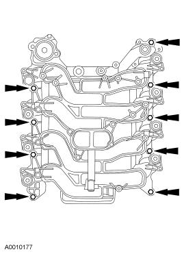
10 32. Remove the nine bolts retaining the intake manifold. 33. Remove the intake manifold. Discard the intake manifold gaskets Rjnq5XZM5czck 10/22
11 34. NOTICE: If the engine is repaired or replaced because of upper engine failure, typically including valve or piston damage, check the intake manifold for metal debris. If metal debris is found, install a new intake manifold. Failure to follow these instructions can result in engine damage. Installation Inspect the throttle body, the intake manifold and their sealing surfaces for damage. 1. NOTICE: Do not use metal scrapers, wire brushes, power abrasive discs or any other abrasive means to clean the sealing surfaces. These tools cause scratches and gouges which can cause leak paths. Use a plastic scraping tool to clean sealing surfaces. Clean and inspect all sealing surfaces. 2. Position the intake manifold gaskets and the intake manifold Rjnq5XZM5czck 11/22

12 3. Loosely install the nine bolts. 4. Install the thermostat. Install the thermostat. Install a new O ring seal Rjnq5XZM5czck 12/22

. http://content.chiltonsonline.")
13 5. NOTE: The thermostat housing bolts are tightened in sequence with the intake manifold bolts. Loosely install the thermostat housing and bolts. 6. Tighten the bolts in two stages, in the sequence shown. Stage 1: Tighten to 2 Nm (18 lb in). Stage 2: Tighten to 25 Nm (18 lb ft) Rjnq5XZM5czck 13/22
14 7. Install the eight ignition coils and bolts. 8. NOTE: LH shown; RH similar. Connect the eight fuel injector electrical connectors. 9. NOTE: LH shown; RH similar. Connect the eight ignition coil electrical connectors. 10. Connect the fuel pressure sensor vacuum hose and electrical connector Rjnq5XZM5czck 14/22


15 11. Install the PCV hose and valve. 12. Install the new throttle body adapter gasket. 13. Install the throttle body and adapter assembly. Install the four bolts Rjnq5XZM5czck 15/22

16 14. Install the exhaust manifold to EGR valve tube and tighten the fitting in two stages. Stage 1: Hand tighten the fittings. Stage 2: Tighten to 50 Nm (37 lb ft). 15. Connect the brake booster and the main engine vacuum harnesses. 16. Connect the EGR vacuum hose Rjnq5XZM5czck 16/22
17 17. Install the evaporative emission canister purge valve. 18. Connect the EGR vacuum regulator solenoid connections. 19. If equipped, connect the auxiliary heater hoses. For additional information, refer to Climate Control System General Information and Diagnostics Rjnq5XZM5czck 17/22

18 20. Connect the evaporative emissions hose on the intake manifold. 21. Position back the transmission fluid indicator and tube. Install the retaining nut. 22. Install the transmission fluid filler tube bracket and bolt. 23. Install the generator upper support bracket Rjnq5XZM5czck 18/22


19 24. Install the differential pressure feedback EGR system bracket. 25. Connect the differential pressure feedback EGR sensor. Connect the electrical connector. Connect the two hoses. 26. If equipped, connect the coolant hoses to the TB Rjnq5XZM5czck 19/22

20 27. Connect the coolant hose. 28. Connect the upper radiator hose. 29. Connect the TP sensor electrical connector. Push back the red clip Rjnq5XZM5czck 20/22

21 30. Connect the electronic TB electrical connector. Push back the red clip. 31. Install the air cleaner outlet pipe and tighten the clamp. Connect the engine vent tube. 32. Connect the MAF sensor and position the ACL. 33. Install the ACL. Install the four bolts. Tighten the clamp Rjnq5XZM5czck 21/22

22 34. Connect the fuel hose spring lock couplings. For additional information, refer to Fuel System General Information Gasoline and Diesel. 35. Install the engine cover. For additional information, refer to Interior Trim and Ornamentation. 36. Connect the battery ground cable. For additional information, refer to Battery, Mounting and Cables. 37. Fill and bleed the engine cooling system. For additional information, refer to Engine Cooling Rjnq5XZM5czck 22/22
2001 Lincoln LS Workshop Manual
 Page 1 of 10 SECTION 303-01B: Engine 3.9L 2001 Lincoln LS Workshop Manual IN-VEHICLE REPAIR Procedure revision date: 05/16/2000 Intake Manifold Removal 1. Disconnect the battery ground cable. For additional
1999 F-150/250 Workshop Manual
 Page 1 of 8 SECTION 303-01B: Engine 4.6L and 5.4L IN-VEHICLE REPAIR Procedure revision date: 02/03/1999 Intake Manifold Lightning Removal WARNING: Do not smoke or carry lighted tobacco or open flame of
1998 F-150/250 Workshop Manual
 Page 1 of 13 SECTION 303-01B: Engine 4.6L and 5.4L 1998 F-150/250 Workshop Manual IN-VEHICLE REPAIR Procedure revision date: 03/07/2000 Intake Manifold Removal WARNING: Do not smoke or carry lighted tobacco
Zoom and Print Options
 Vehicle» Engine, Cooling and Exhaust» Engine» Cylinder Head Assembly» Valve Cover» Service and Repair» Procedures» LH Valve Cover LH Removal 1. Disconnect the battery ground cable. 2. Remove the air cleaner
2000 Econoline Workshop Manual. 3. Install the upper intake manifold. 2. NOTE: Tighten the bolts in two stages.
 2. NOTE: Tighten the bolts in two stages. Tighten the bolts in the sequence shown. Stage 1: Tighten to 2 Nm (18 lb-in). Stage 2: Tighten to 10 Nm (89 lb-in). 3. Install the upper intake manifold. Position
 Page 1 of 14 Oil Pan Removal & Installation 4.2L Engine 4WD Vehicles To Remove: 1. Before servicing the vehicle refer to the precautions at the beginning of this section. 2. Raise and support the vehicle.
1999 E-Series Workshop Manual
 http://www.fordservicecontent.com/pubs/content/~wsxm/~mus~len/21/sxm31c16.h... Page 1 of 3 SECTION 303-01C: Engine 6.8L 1999 E-Series Workshop Manual IN-VEHICLE REPAIR Procedure revision date: 06/30/1998
IN-VEHICLE SERVICING > VALVE COVER - RH
 Page 1 of 20 Service Manual: ENGINE - 5.4L (3V)- F-150 & MARK LT IN-VEHICLE SERVICING > VALVE COVER - RH 2008 Ford Pickup 5.4L Eng F150 Material Item Specification Motorcraft Metal Surface Prep ZC-31 PAG
2011 Mercury Grand Marquis LS
 Fig. 6: Locating Intake Manifold Crash Bracket With Tie Strap 24. Remove the intake manifold crash bracket bolt. 25. Disconnect the fuel rail pressure and temperature sensor vacuum and electrical connectors.
Intake Components 1117
 Item Part Number Description 1 W705654 Bolt 2 N807309 Bolt (2 req'd) 3 9F460 Bracket 4 N807071 Bolt (5 req'd) 5 9A448 Intake manifold (upper) 6 9E498 Vacuum harness 7 9F792 Fuel injection supply manifold
SECTION A: Engine 4.0L SOHC 2007 Explorer/Mountaineer/Explorer Sport Trac Workshop M. IN-VEHICLE REPAIR Procedure revision date: 11/20
 2007 Explorer Sport Trac Applies to: 4.0L SOHC Report a problem wit SECTION 303-01A: Engine 4.0L SOHC 2007 Explorer/Mountaineer/Explorer Sport Trac Workshop M IN-VEHICLE REPAIR Procedure revision date:
Zoom and Print Options
 Vehicle» Engine, Cooling and Exhaust» Engine» Cylinder Head Assembly» Valve Cover» Service and Repair» Procedures» RH Valve Cover RH Removal 1. Disconnect the battery ground cable. 2. Remove the air cleaner
2002 Mustang Workshop Manual
 Page 1 of 13 SECTION 303-01B: Engine 4.6L (2V) 2002 Mustang Workshop Manual REMOVAL Procedure revision date: 01/02/2003 Cylinder Heads Special Tool(s) Remover, Crankshaft Vibration Damper 303-009 (T58P-6316-D)
DISASSEMBLY. Engine. CAUTION: Remove the cylinder heads before removing the crankshaft. Failure to do so can result in engine damage.
 303-01A-1 DISASSEMBLY Engine Special Tool(s) Remover, Crankshaft Vibration Damper 303-101 (T74P-3616-A) Special Tool(s) Crankshaft Socket 303-674 303-01A-1 Remover, Crankshaft Vibration Damper 303-773
2002 Explorer Sport/Sport Trac Workshop Manual
 Page 1 of 17 SECTION 303-01: Engine 4.0L Single Overhead Camshaft (SOHC) IN-VEHICLE REPAIR Procedure revision date: 07/13/2005 Cylinder Head Special Tool(s) Spark Plug Wire Remover 303-106 (T74P-6666-A)
IN-VEHICLE REPAIR. Upper Intake Manifold
 303-01-1 Engine 3.9L and 4.2L 303-01-1 IN-VEHICLE REPAIR Upper Intake Manifold Special Tool(s) Remover, Spark Plug Wire 303-106 (T74P-6666-A) Material Item Silicone Brake Caliper Grease and Dielectric
M-9424-M50B 2012 Boss 302 Intake Manifold INSTALLATION INSTRUCTIONS
 !!! PLEASE READ ALL OF THE FOLLOWING INSTRUCTIONS CAREFULLY PRIOR TO INSTALLATION. WARNING: CUSTOM CALIBRATION REQUIRED! CALIBRATION NOT INCLUDED! KIT CONTENTS: 1) Intake Manifold Assembly 2) Assembly
2006 Expedition/Navigator Workshop Manual
 7. Remove the RH variable camshaft timing (VCT) oil control solenoid. For additional information, refer to Section 303-14. 8. Remove the RH ignition coils. For additional information, refer to Section
Cylinder Head. Special Tool(s) Compressor, Valve Spring (T93P-6565-AR) Heavy Duty Floor Crane or equivalent
 Compressor, Valve Spring (T93P-6565-AR) Heavy Duty Floor Crane or equivalent") SECTION 303-01C: Engine 5.4L (4V) 2009 Mustang Workshop Manual INSTALLATION Procedure revision date: 04/03/2009 Cylinder Head Special Tool(s) Compressor, Valve Spring 303-452 (T93P-6565-AR) Heavy Duty
SECTION 303-01C: Engine 5.4L (4V) 2009 Mustang Workshop Manual INSTALLATION Procedure revision date: 04/03/2009 Cylinder Head Special Tool(s) Compressor, Valve Spring 303-452 (T93P-6565-AR) Heavy Duty
Disconnect the breather tube from the air cleaner outlet duct.
 Disconnect the breather tube from the air cleaner outlet duct. Disconnect the IAT sensor harness connector. Remove the air cleaner outlet duct retaining wingnut. Separate the air cleaner outlet duct from
Engine. Special Tool(s) Compressor, Piston Ring 303-D032 (D81L-6002-C) or equivalent. Compressor, Valve Spring (T93P-6565-AR)
 Compressor, Piston Ring 303-D032 (D81L-6002-C) or equivalent. Compressor, Valve Spring (T93P-6565-AR)") SECTION 303-01C: Engine 5.4L (4V) 2009 Mustang Workshop Manual ASSEMBLY Procedure revision date: 12/12/2008 Engine Special Tool(s) Compressor, Piston Ring 303-D032 (D81L-6002-C) or equivalent Compressor,
SECTION 303-01C: Engine 5.4L (4V) 2009 Mustang Workshop Manual ASSEMBLY Procedure revision date: 12/12/2008 Engine Special Tool(s) Compressor, Piston Ring 303-D032 (D81L-6002-C) or equivalent Compressor,
DESCRIPTION AND OPERATION
 303-01B-10 Engine 3.0L 303-01B-10 DESCRIPTION AND OPERATION Upper Engine Components G72932 en 303-01B-11 Engine 3.0L 303-01B-11 DESCRIPTION AND OPERATION (Continued) Item Part Number Description 1 9H589
Lower Intake Manifold Replacement
 Lower Intake Manifold Replacement Removal Procedure 1. Turn OFF all the lamps and the accessories. 2. Ensure the ignition switch is in the OFF position. 3. Disconnect the negative battery cable from the
10/30/2018 Intake Manifold Replacement (RPOs LY2/LY6) 2007 GMC Truck Yukon Denali MotoLogic
 2007 GMC Truck Yukon Denali MotoLogic") 2007 Yukon Denali Applies to: 4.8L, 5.3L, 6.0L and 6.2L Report a problem with this article Removal Procedure 1. Remove the air cleaner outlet duct. Refer to Air Cleaner Resonator Outlet Duct Replacement.
2007 Yukon Denali Applies to: 4.8L, 5.3L, 6.0L and 6.2L Report a problem with this article Removal Procedure 1. Remove the air cleaner outlet duct. Refer to Air Cleaner Resonator Outlet Duct Replacement.
Intake Manifold Replacement
 Page 1 of 14 2004 Chevrolet TrailBlazer - 4WD Bravada, Envoy, Rainier, TrailBlazer (VIN S/T) Service Manual Engine Engine Mechanical - 4.8L, 5.3L, and 6.0L Repair Instructions - On Vehicle Document ID:
2/18/2017 Cylinder Head Assembly Service and Repair, Removal and Replacement: Cylinder Head
 Cylinder Head http://repair.alldata.com/alldata/article/display.action?componentid=65&itypeid=401&nonstandardid=2762152&vehicleid=47645&miles=&printfriendl 1/17 RH Splash Shield Accessory Drive Belt, Thermostat
Intake Manifold Removal
 PLEASE READ ALL OF THE FOLLOWING INSTRUCTIONS CAREFULLY PRIOR TO INSTALLATION. AT ANY TIME YOU DO NOT UNDERSTAND THE INSTRUCTIONS Parts included: -GT350 Intake manifold M-944-M5 -GT350 Air bucket w/filter.
Intake Manifold Replacement
 Document ID# 738735 2002 Chevrolet Chevy Suburban - 4WD Print Intake Manifold Replacement Removal Procedure Important: The intake manifold, throttle body, fuel rail, and injectors may
 Page 1 of 6 Section 03-01C: Engine 3.4L SHO 1999 Taurus/Sable Workshop Manual IN-VEHICLE SERVICE Procedure revision date: 06/25/1998 Intake Manifold Upper Removal 1. Disconnect battery ground cable (14301).
 Page 1 of 8 SECTION 303-01A: Engine 2.3L 2002 Ranger Workshop Manual IN-VEHICLE REPAIR Procedure revision date: 10/20/2004 Intake Manifold Removal 1. Remove the accelerator control snow shield. 2. Remove
Engine Front Cover. Special Tool(s) Lifting Bracket, Engine (2 required) 303-D087 (D93P-6001-A1) or equivalent. Support Bar, Engine 303-F070
 Lifting Bracket, Engine (2 required) 303-D087 (D93P-6001-A1) or equivalent. Support Bar, Engine 303-F070") SECTION 303-01C: Engine 5.4L (4V) 2009 Mustang Workshop Manual IN-VEHICLE REPAIR Procedure revision date: 07/25/2008 Engine Front Cover Special Tool(s) Lifting Bracket, Engine (2 required) 303-D087 (D93P-6001-A1)
SECTION 303-01C: Engine 5.4L (4V) 2009 Mustang Workshop Manual IN-VEHICLE REPAIR Procedure revision date: 07/25/2008 Engine Front Cover Special Tool(s) Lifting Bracket, Engine (2 required) 303-D087 (D93P-6001-A1)
Zoom and Print Options
 Vehicle» Engine, Cooling and Exhaust» Engine» Service and Repair» Removal and Replacement» Engine Replacement Engine Replacement ^ Tools Required - J 38185 Hose Clamp Pliers Removal Procedure 1. Remove
 Page 1 of 5 303-01B Engine 3.0L (4V) 2004 Escape IN-VEHICLE REPAIR Procedure revision date: 05/26/2005 Engine Front Cover Material Removal Item Motocraft Metal Surface Cleaner ZC-21 Silicone Gasket and
1 of 12 10/5/2015 8:11 AM
 1 of 12 10/5/2015 8:11 AM REMOVAL 1. Perform the fuel pressure release procedure See: Fuel Pressure Release > Procedures > Fuel System Pressure Release Procedure. 2. Recover the refrigerant from the refrigerant
ASSEMBLY/INSTALLATION INSTRUCTIONS
 ASSEMBLY/INSTALLATION INSTRUCTIONS AURORA 3000 & 4000 SCORPION TURBO SYSTEM NOTICE: The engine oil must be changed any time the turbocharger is removed from the engine. The passages in the block underneath
INTAKE MANIFOLD INSPECTION/REPLACEMENT
 ATTACHMENT III Owner Notification Program 99M01 INTAKE MANIFOLD INSPECTION/REPLACEMENT AFFECTED VEHICLES: 1997 AND 1998 CROWN VICTORIA POLICE INTERCEPTOR VEHICLES WITH 4.6L SOHC ENGINES BUILT AT THE ST.
IN-VEHICLE REPAIR. Cylinder Head. Special Tool(s) Timing Tool, Crankshaft TDC (T97T-6303-A) or. Special Tool(s) equivalent
 Timing Tool, Crankshaft TDC (T97T-6303-A) or. Special Tool(s) equivalent") 303-01A-1 IN-VEHICLE REPAIR Cylinder Head Special Tool(s) Torque Wrench Extension 303-575 (T97T-6256-F) or equivalent Special Tool(s) 303-01A-1 Timing Tool, Crankshaft TDC 303-573 (T97T-6303-A) or equivalent
303-01A-1 IN-VEHICLE REPAIR Cylinder Head Special Tool(s) Torque Wrench Extension 303-575 (T97T-6256-F) or equivalent Special Tool(s) 303-01A-1 Timing Tool, Crankshaft TDC 303-573 (T97T-6303-A) or equivalent
STARTER COMPONENTS FOR REMOVAL AND INSTALLATION
 Removal STARTER COMPONENTS FOR REMOVAL AND INSTALLATION Starter Components For Removal And Installation REMOVAL OF STARTER 1. DISCONNECT CABLE FROM NEGATIVE TERMINAL OF BATTERY CAUTION: Work must be started
 Page 1 of 6 Section 03-01C: Engine, 7.5L MFI 1996 Bronco/F-Series Workshop Manual IN-VEHICLE SERVICE Procedure revision date: 06/19/2000 Cylinder Heads Removal SPECIAL SERVICE TOOL(S) REQUIRED Description
 Page 1 of 8 303-01A Engine 2.3L 2007 Escape/Mariner/Escape Hybrid/Mariner Hybrid IN-VEHICLE REPAIR Procedure revision date: 10/05/2008 Cylinder Head Special Tool(s) Alignment Plate, Camshaft 303-465 (T94P-6256-CH)
1. With the vehicle in NEUTRAL, position it on a hoist. For additional information, refer to Section
 SECTION 303-01C: Engine 5.4L (4V) 2009 Mustang Workshop Manual REMOVAL Procedure revision date: 07/25/2008 Engine Special Tool(s) Heavy Duty Floor Crane 014-00071 or equivalent Lifting Bracket, Engine
2011 Transit Connect Workshop Manual
 SECTION 303-12: Intake Air Distribution and Filtering REMOVAL AND INSTALLATION Procedure revision date: 09/23/2010 Intake Air System Components - Exploded View Item Part Number 1 9F991 Throttle Body (TB)
2002 Crown Victoria/Grand Marquis Workshop Manual
 Page 1 of 24 SECTION 303-01: Engine 2002 Crown Victoria/Grand Marquis Workshop Manual INSTALLATION Procedure revision date: 01/02/2003 Cylinder Heads Special Tool(s) Installer, Crankshaft Vibration Damper
2002 Crown Victoria/Grand Marquis Workshop Manual
 Page 1 of 9 SECTION 303-04: Fuel Charging and Controls 2002 Crown Victoria/Grand Marquis Workshop Manual REMOVAL AND INSTALLATION Procedure revision date: 06/13/2001 Fuel Injection Supply Manifold Material
Cylinder Head Replacement
 CYLINDER HEAD REPLACEMENT (EN... CYLINDER HEAD REPLACEMENT (ENGINE MECHANICAL - 1.6L) Document ID# 1430093 Cylinder Head Replacement Tools Required J 45059 Angle Meter KM-470-B Angular Torque Gauge J 42492-A
 Page 1 of 9 SECTION 303-01B: Engine 2.0L SPI 2002 Focus Workshop Manual ASSEMBLY Procedure revision date: 12/14/2000 Engine Special Tool(s) Crankshaft Rear Seal Pilot 303-329 (T88P-6701-B2) Crankshaft
FREE $15 Gift Card for every $100 spent on Ship To Home orders. Find Out How
 1 of 29 10/12/2011 5:05 PM FREE $15 Gift Card for every $100 spent on Ship To Home orders. Find Out How Ford Ranger/Explorer/Mountaineer 1991-1999 Intake Manifold REMOVAL & INSTALLATION Print The engines
Exhaust Gas Recirculation Valve, Replace J S file://c:\program Files\cosids\DATA\TMP\ rtf.html. Remove
 1 Page 1 of 20 Exhaust Gas Recirculation Valve, Replace J982500 Remove 1. Disconnect battery negative lead 2. Disconnect hose (1) from oil filler on air cleaner assembly, then move to one side Release
Engine Front Cover. Special Tool(s) 3-Jaw Puller 303-D121 or equivalent. Installer, Front Cover Oil Seal (T88T-6701-A)
 3-Jaw Puller 303-D121 or equivalent. Installer, Front Cover Oil Seal (T88T-6701-A)") SECTION 303-01B: Engine 4.6L (3V) 2009 Mustang Workshop Manual IN-VEHICLE REPAIR Procedure revision date: 05/23/2008 Engine Front Cover Special Tool(s) 3-Jaw Puller 303-D121 or equivalent Installer, Front
SECTION 303-01B: Engine 4.6L (3V) 2009 Mustang Workshop Manual IN-VEHICLE REPAIR Procedure revision date: 05/23/2008 Engine Front Cover Special Tool(s) 3-Jaw Puller 303-D121 or equivalent Installer, Front
IN-VEHICLE SERVICE. Engine Components
 file://c:\tso\tsocache\vdtom_5368\svk~us~en~file=svk31a14.htm~gen~ref.htm Page 1 of 10 Section 03-01A: Engine, 2.3L I-4 IN-VEHICLE SERVICE 1997 Ranger Workshop Manual Engine Components The views shown
 Page 1 of 6 Section 303-01A: Basic Engine 4.2L REMOVAL 1997 F-150/250 Workshop Manual Engine Special Service Tool(s) Engine Lifting Bracket or equivalent 014-00730 Removal 1. Remove the hood. 2. On A/C
COMPONENT LOCATOR > DISASSEMBLED VIEWS
 Page 1 of 45 2006 Pontiac Grand Prix 3.8L Eng Base Service Manual: ENGINE MECHANICAL - 3.8L COMPONENT LOCATOR > DISASSEMBLED VIEWS Fig 1: Engine Block Component Views Callout Component Name 100 Engine
2007 Escape/Mariner/Escape Hybrid/Mariner Hybrid Workshop Manual
 SECTION 303-08A: Engine Emission 2007 Escape/Mariner/Escape Hybrid/Mariner Hybrid Control 2.3L Positive Crankcase Ventilation (PCV) System Components Exploded View View (157 KB) Printable Item Part Number
IN-VEHICLE REPAIR. Engine Front Cover
 303-01B-1 IN-VEHICLE REPAIR Engine Front Cover Material Item Specification 303-01B-1 Special Tool(s) Motorcraft SAE 5W-20 WSS-M2C930-A Premium Synthetic Blend 3-Jaw Puller Motor Oil 303-D121 XO-5W20-QSP
Cylinder Block Cradle
 SECTION 303-01A: Engine 4.0L SOHC 2009 Mustang Workshop Manual IN-VEHICLE REPAIR Procedure revision date: 01/27/2010 Cylinder Block Cradle Special Tool(s) Lifting Bracket, Engine 303-050 (T70P-6000) Support
2003 Nissan-Datsun Truck Frontier 4WD V6-3.3L (VG33E)
") 1 of 15 8/7/2016 2:34 PM 2003 Nissan-Datsun Truck Frontier 4WD V6-3.3L (VG33E) Vehicle» Engine, Cooling and Exhaust» Engine» Cylinder Head Assembly» Service and Repair» Removal and Installation 2 of 15
1 of 15 8/7/2016 2:34 PM 2003 Nissan-Datsun Truck Frontier 4WD V6-3.3L (VG33E) Vehicle» Engine, Cooling and Exhaust» Engine» Cylinder Head Assembly» Service and Repair» Removal and Installation 2 of 15
2001 Ranger Workshop Manual. 1. Drain the cooling system. For additional information, refer to Section
 Exhaust Gas Recirculation (EGR) Valve 2.3L 1. Drain the cooling system. For additional information, refer to Section 303-03. 2. Disconnect the battery ground cable. For additional information, refer to
1501 Industrial Way N., Toms River, NJ Fax: PACKING LIST
 1/6/04 1501 Industrial Way N., Toms River, NJ 08755 732-349-2109 Fax:732-244-0867 MODERATE - Installation requires metric tools and possibly cutting and drilling. The ability to closely follow instructions
 Page 1 of 21 303-01C Engine 5.4L (3V) 2009 F-150 REMOVAL Procedure revision date: 03/26/2009 Cylinder Head Special Tool(s) 3 Jaw Puller 303-D121 or equivalent Compressor, Valve Spring 303-1039 Holding
Cylinder Head. Special Tool(s) 3-Jaw Puller 303-D121 or equivalent. Compressor, Valve Spring
 3-Jaw Puller 303-D121 or equivalent. Compressor, Valve Spring") SECTION 303-01B: Engine 4.6L (3V) 2009 Mustang Workshop Manual REMOVAL Procedure revision date: 03/15/2009 Cylinder Head Special Tool(s) 3-Jaw Puller 303-D121 or equivalent Compressor, Valve Spring 303-1039
SECTION 303-01B: Engine 4.6L (3V) 2009 Mustang Workshop Manual REMOVAL Procedure revision date: 03/15/2009 Cylinder Head Special Tool(s) 3-Jaw Puller 303-D121 or equivalent Compressor, Valve Spring 303-1039
DISASSEMBLY Procedure revision date: 11/22/2001
 Page 1 of 31 Evan Groenke From: Daniel Lelovic [dlelovic@rogers.com] Sent: May 8, 2005 12:06 PM To: 'Evan Groenke' Subject: 2.5 L Engine Disassembly SECTION 303-01B: Engine 2.5L 2000 Contour/Mystique Workshop
1988 Ford F-350 PICKUP
 1988 Ford F-350 PICKUP Submodel: Engine Type: V8 Liters: 7.5 Fuel Delivery: FI Fuel: GAS 1987 93 4.9L Engine The intake and exhaust manifolds on these engines are known as combination manifolds and are
REMOVAL. Cylinder Head. All cylinder heads. 1. Remove the engine. For additional information, refer to Engine in this section.
 303-01B-1 303-01B-1 REMOVAL Cylinder Head Material Item Specification Special Tool(s) Motorcraft Metal Surface Prep Modular Engine Lift Bracket ZC-31 303-F047 (014-00073) or equivalent Silicone Gasket
9/20/2017 Automatic Transaxle/Transmission External Controls - Selector Lever Cable - Removal and Installation 2008 Ford Edge MotoLogic
 2008 Edge SECTION 307-05: Automatic Transaxle/Transmission External Controls REMOVAL AND INSTALLATION 2008 Edge/MKX Workshop Manual Procedure revision date: 06/17/2009 Report a problem with this article
REMOVAL. Fig Sized for Print
 ALLDATA Online - 2000 Dodge Truck Grand Caravan FWD V6-3.3L VIN R - Intake M... Page 1 of 10 REMOVAL 1. Remove windshield wiper module. 2. Perform fuel system pressure release procedure (before attempting
Crankshaft Rear Seal with Retainer Plate
 SECTION 303-01C: Engine 5.4L (4V) 2009 Mustang Workshop Manual IN-VEHICLE REPAIR Procedure revision date: 07/25/2008 Crankshaft Rear Seal with Retainer Plate Special Tool(s) Installer, Crankshaft Rear
 ALLDATA Online - 1997 Ford Truck F 150 2WD Pickup V8-5.4L SOHC VIN L - Servi... Page 1 of 22 Home Account Contact ALLDATA Log Out Help BILL SEIDLES MITSUBISHI Select Vehicle New TSBs Technician's Reference
SECTION C Engine 5.4L (3V)
") 303-01C-i Engine 5.4L (3V) 303-01C-i SECTION 303-01C Engine 5.4L (3V) CONTENTS PAGE IN-VEHICLE REPAIR Engine Front Cover... 303-01C-2 303-01C-2 Engine 5.4L (3V) 303-01C-2 IN-VEHICLE REPAIR Engine Front
303-01C-i Engine 5.4L (3V) 303-01C-i SECTION 303-01C Engine 5.4L (3V) CONTENTS PAGE IN-VEHICLE REPAIR Engine Front Cover... 303-01C-2 303-01C-2 Engine 5.4L (3V) 303-01C-2 IN-VEHICLE REPAIR Engine Front
2001 Ford Windstar ENGINES 3.8L V6 - VIN 4 - Windstar
 COWL TOP VENT PANEL 1. Remove windshield wiper pivot arms. Remove cowl top vent panel retaining screws. Release cowl top vent panel retaining clips. Remove windshield wiper fluid hose. Remove cowl top
M-9424-M50CJ INTAKE MANIFOLD INSTALLATION INSTRUCTIONS
 Please visit www.fordracingparts.com for the most current instruction information!!! PLEASE READ ALL OF THE FOLLOWING INSTRUCTIONS CAREFULLY PRIOR TO INSTALLATION. AT ANY TIME YOU DO NOT UNDERSTAND THE
Ford Racing Laser Etched Valve Covers (05-10 GT, GT500)
") Applicable Part Numbers: M-6582-FR3VBL (Blue) M-6582-FR3VBLK (Black) M-6582-C543V (Chrome) List of Tools: 1/4 ratchet 3/8 ratchet 8mm socket 10mm socket 7mm socket 1/4 & 3/8 extensions Plastic gasket scraper
Applicable Part Numbers: M-6582-FR3VBL (Blue) M-6582-FR3VBLK (Black) M-6582-C543V (Chrome) List of Tools: 1/4 ratchet 3/8 ratchet 8mm socket 10mm socket 7mm socket 1/4 & 3/8 extensions Plastic gasket scraper
1997 Volvo 850 GLT. Fig. 2: Removing Drive Shaft, Engine Mount Bolt & Torque Arm (5-Cylinder) Courtesy of VOLVO CARS OF NORTH AMERICA.
 Courtesy of VOLVO CARS OF NORTH AMERICA.") Fig. 2: Removing Drive Shaft, Engine Mount Bolt & Torque Arm (5-Cylinder) 4. Remove front exhaust pipe nuts and springs. Remove front exhaust pipe bolts. Disconnect speedometer. Remove engine mounting
Fig. 2: Removing Drive Shaft, Engine Mount Bolt & Torque Arm (5-Cylinder) 4. Remove front exhaust pipe nuts and springs. Remove front exhaust pipe bolts. Disconnect speedometer. Remove engine mounting
ENGINE AND EMISSION CONTROL
 17-1 ENGINE AND EMISSION CONTROL CONTENTS ENGINE CONTROL SYSTEM........ 3 SERVICE SPECIFICATION............... 3 ON-VEHICLE SERVICE.................. 3 Accelerator Cable Check and Adjustment... 3 ACCELERATOR
Disconnect the APP sensor harness connector. See Fig. 4. Remove the accelerator pedal mounting nuts. Remove the APP assembly.
 ENGINE CONTROLS - REMOVAL, OVERHAUL & INSTALLATION - 6.6L DIESEL... Page 1 of 41 FUEL SYSTEMS ACCELERATOR PEDAL POSITION SENSOR Removal & Installation Disconnect the APP sensor harness connector. See Fig.
DISASSEMBLY. Engine. Special Tool(s) Locking Tool, Camshaft Phaser Sprocket Special Tool(s)
 Locking Tool, Camshaft Phaser Sprocket Special Tool(s)") 303-01B-1 DISASSEMBLY Engine Special Tool(s) Remover, Crankshaft Rear Slinger 303-514 (T95P-6701-AH) Special Tool(s) 303-01B-1 Locking Tool, Camshaft Phaser Sprocket 303-1046 Remover, Crankshaft Rear Seal
303-01B-1 DISASSEMBLY Engine Special Tool(s) Remover, Crankshaft Rear Slinger 303-514 (T95P-6701-AH) Special Tool(s) 303-01B-1 Locking Tool, Camshaft Phaser Sprocket 303-1046 Remover, Crankshaft Rear Seal
1991 Volkswagen Vanagon Syncro
 corner of radiator. See Fig. 1. Fig. 1: Bleeding Cooling System 2. Open bleeder valve in engine compartment (turn counterclockwise). See Fig. 1. Fill expansion tank until full. Start and run engine at
FULL BORE PERFORMANCE EXHAUST MANIFOLDS F-150 ECOBOOST 3.5L
 2018-01-15 FORD F150 ECOBOOST 3.5L FULL BORE PERFORMANCE MANIFOLD SET (PART #500101X) 1 FULL BORE PERFORMANCE EXHAUST MANIFOLDS F-150 ECOBOOST 3.5L INSTALLATION INSTRUCTIONS 2011-2012 FORD F150 3.5L ECOBOOST
ALLDATA Online Chevy Truck S10/T10 Blazer 2WD V6-4.3L VIN W - Intake... Intake Manifold Replacement (Upper)
") ALLDATA Online - 2001 Chevy Truck S10/T10 Blazer 2WD V6-4.3L VIN W - Intake... Page 1 of 21 Home Account Contact ALLDATA Log Out Help PAUL REDEHOFT Select Vehicle New TSBs Technician's Reference Component
ALLDATA Online - 2001 Chevy Truck S10/T10 Blazer 2WD V6-4.3L VIN W - Intake... Page 1 of 21 Home Account Contact ALLDATA Log Out Help PAUL REDEHOFT Select Vehicle New TSBs Technician's Reference Component
Ford Racing Performance Improvement Intake Manifold (96-04 GT) Time Necessary: Approximately 4 hours
 Time Necessary: Approximately 4 hours") Ford Racing Performance Improvement Intake Manifold (96-04 GT) Time Necessary: Approximately 4 hours Tools Required: Ratchet and socket set Torque wrench Large adjustable wrench Needle nose pliers A dozen
Ford Racing Performance Improvement Intake Manifold (96-04 GT) Time Necessary: Approximately 4 hours Tools Required: Ratchet and socket set Torque wrench Large adjustable wrench Needle nose pliers A dozen
 Page 1 of 8 Section 03-01: Engine, 4.6L IN-VEHICLE SERVICE 1994 Town Car/Crown Victoria/Grand Marquis Workshop Manual Oil Pan and Oil Pump Screen Cover and Tube Town Car Removal 1. Disconnect battery ground
ENGINE AND EMISSION CONTROL
 17-1 ENGINE AND EMISSION CONTROL CONTENTS EMISSION CONTROL SYSTEM... 2 GENERAL... 2 Outline of Changes... 2 GENERAL INFORMATION... 2 SERVICE SPECIFICATION... 2 VACUUM HOSE... 3 Vacuum Hose Piping Diagram...
Ford 6.0L. Part #: Part #: BD GASKET PART# will be needed for this installation.
 1 BD EGR COOLER 2003-2007 Ford 6.0L Part #: 1090201 Part #: 1090202 PLEASE READ ALL INSTRUCTIONS BEFORE INSTALLATION BD GASKET PART# 1090002 will be needed for this installation. 2 K I T C O N T E N T
2003 Taurus/Sable Workshop Manual
 Page 1 of 24 SECTION 303-01A: Engine 3.0L (2V) ASSEMBLY 2003 Taurus/Sable Workshop Manual Engine Special Tool(s) Piston Ring Compressor 303- D032 (D81L-6002-C) Camshaft Bearing Set 303-017 (T65L-6250-A)
Audi > B4 > Liter V6 2V Engine Mechanical, Engine Code(s): AAH, AFC 10 Engine Assembly
: AAH, AFC 10 Engine Assembly") Audi > B4 > 1993 1995 2.8 Liter V6 2V Engine Mechanical, Engine Code(s): AAH, AFC 10 Engine Assembly Removing The engine is removed from above, after being separated from the transmission. Note: All tie
Audi > B4 > 1993 1995 2.8 Liter V6 2V Engine Mechanical, Engine Code(s): AAH, AFC 10 Engine Assembly Removing The engine is removed from above, after being separated from the transmission. Note: All tie
FUEL PRESSURE REGULATOR
 EG2214 3VZE ENGINE FUEL PRESSURE REGULATOR ONVEHICLE INSPECTION CHECK FUEL PRESSURE (See step 2 on page EG2206) COMPONENTS FOR REMOVAL AND INSTALLATION FUEL PRESSURE REGULATOR REMOVAL 1. DISCONNECT NEGATIVE
2007 Ford Freestyle SEL
 Fig. 279: Exploded View Of Engine Heads, Intake & Exhaust Components Item Part Number Description 1 9D475 Exhaust gas recirculation (EGR) system module 2 9D477 EGR module tube 3 9F485 RH exhaust manifold
Cylinder head, removing and
 Page 1 of 35 15-2 Cylinder head, removing and installing Note: Replace cylinder head bolts. Always replace self-locking nuts, bolts as well as gaskets and O-rings. After installing a replacement cylinder
2010 Transit Connect Workshop Manual. 31. Remove the 3 bolts, thermostat housing and thermostat.
 31. Remove the 3 bolts, thermostat housing and thermostat. 32. Remove the 2 bolts, stud bolt and the A/C compressor. 33. Remove the bolt and the KS. 34. Remove the 8 bolts and the crankcase vent oil separator.
LSX Intake Manifold. #54001 LSX (78mm Throttle Body) #54003 LSX (90mm Throttle Body)
 #54003 LSX (90mm Throttle Body)") LSX Intake Manifold #54001 LSX (78mm Throttle Body) #54003 LSX (90mm Throttle Body) Thank you for your purchase of the most innovative and powerful Gen III (LS1 and LS6) manifold ever developed. We are
LSX Intake Manifold #54001 LSX (78mm Throttle Body) #54003 LSX (90mm Throttle Body) Thank you for your purchase of the most innovative and powerful Gen III (LS1 and LS6) manifold ever developed. We are
1 of 14 11/19/ :45 AM
 1 of 14 11/19/2016 11:45 AM 6F35 Digital Transmission Range (TR) Sensor Removal All vehicles 1. With the vehicle in NEUTRAL, position it on a hoist. 3.0L engine 2. Remove the Air Cleaner (ACL) outlet pipe.
REMOVAL AND INSTALLATION
 303-08-1 Engine Emission Control 303-08-1 REMOVAL AND INSTALLATION Exhaust Gas Recirculation (EGR) Cooler 6.4L Diesel, Vertical Cooler Item Part Number Description 1 Fuel cooler tube 2 W701317 Power steering
2009 PCED Gasoline Engines SECTION 1: Description and Operation. Intake Air System
 2009 PCED Gasoline Engines SECTION 1: Description and Operation Procedure revision date: 05/27/2010 Overview Intake Air Systems The intake air system provides clean air to the engine, optimizes air flow,
1 of 12 11/20/2016 9:32 PM
 1 of 12 11/20/2016 9:32 PM Caution: After removing timing chain, do not turn crankshaft and camshaft separately, or valves will strike piston heads. Apply new engine oil to the sliding surfaces when Installing
2014+ Ram 3.0 EcoDiesel EGR Delete
 2014+ Ram 3.0 EcoDiesel EGR Delete Installation Guide WARNING: This product is for competition use only in a sanctioned racing event. NOT FOR USE ON VEHICLES USED OR REGISTERED FOR USE ON A PUBLIC ROAD
EMISSION CONTROL (AUX. EMISSION CONTROL DEVICES) H4SO
 H4SO") EMISSION CONTROL (AUX. EMISSION CONTROL DEVICES) H4SO SYSTEM OVERVIEW 1. System Overview There are three emission control systems, which are as follows: Crankcase emission control system Exhaust emission
EMISSION CONTROL (AUX. EMISSION CONTROL DEVICES) H4SO SYSTEM OVERVIEW 1. System Overview There are three emission control systems, which are as follows: Crankcase emission control system Exhaust emission
2002 Escape Workshop Manual
 SECTION 303-01A: Engine 2.0L Zetec 2002 Escape Workshop Manual IN-VEHICLE REPAIR Procedure revision date: 10/25/2004 Timing Belt Special Tool(s) Crankshaft TDC Timing Peg 303-574 (T97P-6000-A) Camshaft
2010 Explorer, Mountaineer, Explorer Sport Trac Workshop Manual. IN-VEHICLE REPAIR Procedure revision date: 06/11/2009
 SECTION 303-01B: Engine - 4.6L 2010 Explorer, Mountaineer, Explorer Sport Trac Workshop (3V) Manual IN-VEHICLE REPAIR Procedure revision date: 06/11/2009 Engine Lubrication Components - Exploded View Brackets,
Vehicle Level Engine, Cooling and Exhaust Engine Intake Manifold Service and Repair. Service and Repair
 Page 1 of 11 Home Account Contact ALLDATA Log Out Help BILL SEIDLES MITSUBISHI Select Vehicle New TSBs Technician's Reference Component Search: OK 2005 Suzuki Verona L6-2.5L Conversion Calculator Vehicle
Zoom and Print Options
 Vehicle» Engine, Cooling and Exhaust» Engine» Cylinder Head Assembly» Service and Repair» Procedures» Removal Cylinder Heads http://repair.alldata.com/alldata/article/display.action?componentid=65&itypeid=376&nonstandardid=682956&vehicleid=45317&windowname=maina
Section 7.3 Water Manifold has been updated.
 NUMBER: 08 DD15-11 S.M. REF.: 7.3 ENGINE: DD15 DATE: September 2008 SUBJECT: WATER MANIFOLD PUBLICATION: DDC-SVC-MAN-0002 Section 7.3 Water Manifold has been updated. 7.3 WATER MANIFOLD Coolant flows from