Project Report EMF DETECTOR
|
|
|
- Darrell Knight
- 5 years ago
- Views:
Transcription
 Yashwanth")
 Indian Institute of")
1 Project Report EMF DETECTOR Adarsh Kumar ( ) Yashwanth Sandupatla ( ) Vishesh Arya ( ) Indian Institute of Technology Bombay 1
2 Abstract Deflection instruments like voltmeters and ammeters, such as moving coil, the magnetic vane, electrodynamometer, hot wire and electrostatic instruments cannot be read with a high accuracy due to some disturbing influences. One such example is stray EMF in the vicinity of our experimental setup. We ve made an EMF detector which can detect stray EMF and we can choose suitable location for our experiment accordingly. 2
3 Acknowledgement The efforts we ve made in this project would not have been possible without the kind support and help of many individuals. We would like to extend our sincere thanks to all of them. We are highly indebted to Mr. Nitin Pawar and Prof. Pradeep Sarin for their guidance and constant supervision as well as for providing necessary information regarding the project and also for their support in completing the project. We would like to express our gratitude towards our parents and friends for their kind co-operation, encouragement and giving us such attention and time which helped us in completion of this project. 3
4 Contents 1. Introduction and operation Page 5 2. Algorithm Page 6 3. Arduino Code Page Circuit Diagram Page Snapshots EMF Detector Page Problems Faced Page Scope Page 19 4
5 INTRODUCTION Our purpose is to build an EMF detector which can detect stray EMF in our vicinity so that we can apply that knowledge to carefully choose the environment for experimental setups concerned with accuracy of deflection instruments. We ve used LEDs/7-segment LED display, resistors, solid core wire (antennae) and Arduino. Operation of the detector: Changes in electric fields induce a potential in the antenna wire, which is then read by the Arduino. A code is written which makes LEDs glow whenever Arduino gets any reading of stray EMF in the vicinity. The function the 3.3 megohm resistor is changing the sensitivity of the device. In our charge detector, the antenna picks up a charge from a nearby object and the 3.3 meg-ohm resistor controls how quickly the charge will dissipate to ground, and therefore how sensitive the circuit is to external E-fields. 5
6 ALGORITHM Important Variables: Steps: 1. Sense limit - Variable to control Sensitivity 2. NUMREADINGS - Variable to increase data smoothing 3. val - stores the analog input 4. readings[numreadings] - Array to store readings for smoothing 1. First all the elements are initialized to 0 in the readings array. 2. Then analog input from probe pin 5 is is stored in val. 3. val is the constrained within the sense limit and then mapped to All the readings in the loop till the 15th loop is stored in the variable Total using the readings array.after the 15th loop the Total variable is cleared of the previous readings. 5. The value Total is averaged over the 15 loops and stored in the variable average. 6. The higher the average more number of LED s will glow. 6
7 ARDUINO CODE //EMF Detector //Project by //Vishesh Arya //Yashwanth Sandupatla //Adarsh Kumar #define NUMREADINGS 15 // Variable to increase data smoothing int senselimit = 15; int probepin = 5; // analog 5 int val = 0; // Variable to decrease sensitivity (up to 1023 max) // reading from probepin int LED1 = 2; int LED2 = 3; int LED3 = 4; int LED4 = 5; int LED5 = 6; int LED6 = 7; int LED7 = 8; int LED8 = 9; int LED9 = 10; int LED10 = 11; // connections // to the 10 LEDs // variables for smoothing 7
8 int readings[numreadings]; int index = 0; int total = 0; int average = 0; // the readings from the analog input // the index of the current reading // the running total // final average of the probe reading //Variable to affect the speed of the updates for numbers. Lower the number the faster it updates. int updatetime = 40; void setup() { pinmode(2, OUTPUT); pinmode(3, OUTPUT); pinmode(4, OUTPUT); pinmode(5, OUTPUT); pinmode(6, OUTPUT); pinmode(7, OUTPUT); pinmode(8, OUTPUT); pinmode(9, OUTPUT); pinmode(10, OUTPUT); pinmode(11, OUTPUT); // specify Display outputs Serial.begin(9600); // initiate serial connection for debugging/etc for (int i = 0; i < NUMREADINGS; i++) readings[i] = 0; // initialize all the readings to 0 intro(); //Runs the intro void loop() { 8
9 LEDlow(); val = analogread(probepin); // take a reading from the probe if(val >= 1){ val = constrain(val, 1, senselimit); // if the reading isn't zero, proceed // turn any reading higher than the senselimit value into the senselimit value val = map(val, 1, senselimit, 1, 1023); // remap the constrained value within a 1 to 1023 range total -= readings[index]; readings[index] = val; total += readings[index]; index = index + 1; // subtract the last reading // read from the sensor // add the reading to the total // advance to the next index if (index >= NUMREADINGS) index = 0; // if we're at the end of the array... //...wrap around to the beginning average = total / NUMREADINGS; // calculate the average if (average > 50){ // if the average is over 50 showled0(); // Show a 0 if (average > 150){ // and so on... showled1(); // Show a 1 if (average > 250){ showled2(); // Show a 2 9
10 if (average > 350){ showled3(); // Show a 3 if (average > 450){ showled4(); // Show a 4 if (average > 550){ showled5(); // Show a 5 if (average > 650){ showled6(); // Show a 6 if (average > 750){ showled7(); // Show a 7 if (average > 850){ showled8(); // Show a 8 if (average > 950){ showled9(); // Show a 9 Serial.println(average); // use output to aid in calibrating 10
11 delay(updatetime); //Show the number 0 void showled0(){ LEDlow(); //Show the number 1 void showled1(){ LEDlow(); digitalwrite(led2, HIGH); //Show the number 2 void showled2(){ LEDlow(); digitalwrite(led2, HIGH); digitalwrite(led3, HIGH); //Show the number 3 void showled3(){ LEDlow(); digitalwrite(led2, HIGH); digitalwrite(led3, HIGH); digitalwrite(led4, HIGH); //Show the number 4 void showled4(){ 11
12 LEDlow(); digitalwrite(led2, HIGH); digitalwrite(led3, HIGH); digitalwrite(led4, HIGH); digitalwrite(led5, HIGH); //Show the number 5 void showled5(){ LEDlow(); digitalwrite(led2, HIGH); digitalwrite(led3, HIGH); digitalwrite(led4, HIGH); digitalwrite(led5, HIGH); digitalwrite(led6, HIGH); //Show the number 6 void showled6(){ LEDlow(); digitalwrite(led2, HIGH); digitalwrite(led3, HIGH); digitalwrite(led4, HIGH); digitalwrite(led5, HIGH); digitalwrite(led6, HIGH); digitalwrite(led7, HIGH); //Show the number 7 void showled7(){ 12
13 LEDlow(); digitalwrite(led2, HIGH); digitalwrite(led3, HIGH); digitalwrite(led4, HIGH); digitalwrite(led5, HIGH); digitalwrite(led6, HIGH); digitalwrite(led7, HIGH); digitalwrite(led8, HIGH); //Show the number 8 void showled8(){ LEDlow(); digitalwrite(led2, HIGH); digitalwrite(led3, HIGH); digitalwrite(led4, HIGH); digitalwrite(led5, HIGH); digitalwrite(led6, HIGH); digitalwrite(led7, HIGH); digitalwrite(led8, HIGH); digitalwrite(led9, HIGH); //Show the number 9 void showled9(){ LEDlow(); digitalwrite(led2, HIGH); digitalwrite(led3, HIGH); digitalwrite(led4, HIGH); 13
14 digitalwrite(led5, HIGH); digitalwrite(led6, HIGH); digitalwrite(led7, HIGH); digitalwrite(led8, HIGH); digitalwrite(led9, HIGH); digitalwrite(led10, HIGH); //Resets the display void LEDlow(){ digitalwrite(led1, LOW); digitalwrite(led2, LOW); digitalwrite(led3, LOW); digitalwrite(led4, LOW); digitalwrite(led5, LOW); digitalwrite(led6, LOW); digitalwrite(led7, LOW); void intro(){ showled0(); delay(300); showled1(); delay(300); showled2(); delay(300); showled3(); delay(300); showled4(); delay(300); showled5(); delay(300); showled6(); 14
15 delay(300); showled7(); delay(300); showled8(); delay(300); showled9(); delay(300); LEDlow(); 15
16 CIRCUIT DIAGRAM 16
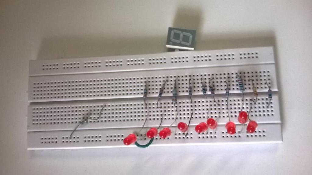
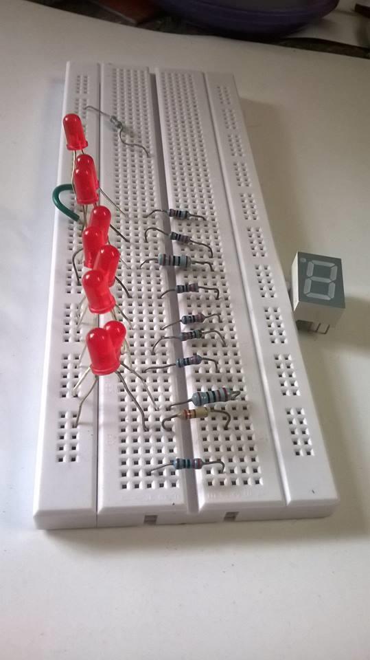
17 EMF DETECTOR-FINALLY!!!! 17
18 PROBLEMS FACED One of the major problems, we faced while making this detector was what should we use as our antennae. Another problem was, stray EMF keeps fluctuating rapidly and is very difficult to observe its nature (i.e high or low). So, to tackle this problem, we used a variable (average) to average some finite number (here 15) of EMF readings in a loop. 18
19 SCOPE In the future, we ll learn how to improve our antennae using a tuning circuit to detect the presence of stray EMF within a broader range. 19
Temperature Sensor. Positive + (to 5 volts.) Ground. To A0 To GND Signal. To 5v
 Ground. To A0 To GND Signal. To 5v") Temperature Sensor This system measures the change in temperature and converts it to a colorful thermometer using LEDs. The first time you run the sketch, you will use the serial monitor to find the lowest
Temperature Sensor This system measures the change in temperature and converts it to a colorful thermometer using LEDs. The first time you run the sketch, you will use the serial monitor to find the lowest
INDUCTANCE FM CHAPTER 6
 CHAPTER 6 INDUCTANCE INTRODUCTION The study of inductance is a very challenging but rewarding segment of electricity. It is challenging because at first it seems that new concepts are being introduced.
HL: Mutual Induction. Mutual / Self-Induction Learning Outcomes. Mutual / Self-Induction Learning Outcomes
 1 Mutual / Self-Induction Learning Outcomes HL: Define and discuss mutual induction for two adjacent coils. HL: Demonstrate mutual induction. HL: Define and describe self-induction. HL: Demonstrate self-induction.
Goals. Introduction (4.1) R = V I
 R = V I") Lab 4. Ohm s Law Goals To understand Ohm s law, used to describe behavior of electrical conduction in many materials and circuits. To calculate electrical power dissipated as heat. To understand and use
Lab 4. Ohm s Law Goals To understand Ohm s law, used to describe behavior of electrical conduction in many materials and circuits. To calculate electrical power dissipated as heat. To understand and use
SECTION 2 SAFETY, TOOLS AND EQUIPMENT, SHOP PRACTICES UNIT 11 CALIBRATING INSTRUMENTS
 SECTION 2 SAFETY, TOOLS AND EQUIPMENT, SHOP PRACTICES UNIT 11 CALIBRATING INSTRUMENTS UNIT OBJECTIVES After studying this unit, the reader should be able to describe instruments used in heating, air conditioning,
3/12/2012 UNIT OBJECTIVES THE NEED FOR CALIBRATION SECTION 2 SAFETY, TOOLS AND EQUIPMENT, SHOP PRACTICES UNIT 11 CALIBRATING INSTRUMENTS
 SECTION 2 SAFETY, TOOLS AND EQUIPMENT, SHOP PRACTICES UNIT 11 CALIBRATING UNIT OBJECTIVES After studying this unit, the reader should be able to describe instruments used in heating, air conditioning,
Chapter 31. Faraday s Law
 Chapter 31 Faraday s Law Michael Faraday 1791 1867 British physicist and chemist Great experimental scientist Contributions to early electricity include: Invention of motor, generator, and transformer
Experimental Question 1: Levitation of Conductors in an Oscillating Magnetic Field
 Experimental Question 1: Levitation of Conductors in an Oscillating Magnetic Field In an oscillating magnetic field of sufficient strength, levitation of a metal conductor becomes possible. The levitation
ELECTRICITY: INDUCTORS QUESTIONS
 ELECTRICITY: INDUCTORS QUESTIONS No Brain Too Small PHYSICS QUESTION TWO (2017;2) In a car engine, an induction coil is used to produce a very high voltage spark. An induction coil acts in a similar way
BASIC ELECTRICAL MEASUREMENTS By David Navone
 BASIC ELECTRICAL MEASUREMENTS By David Navone Just about every component designed to operate in an automobile was designed to run on a nominal 12 volts. When this voltage, V, is applied across a resistance,
(for example A0) on the Arduino you can expect to read a value of 0 (0V) when in its upright position and 1023 (5V) when it is tilted.
 on the Arduino you can expect to read a value of 0 (0V) when in its upright position and 1023 (5V) when it is tilted.") Tilt Sensor Module Tilt sensors are essential components in security alarm systems today. Standalone tilt sensors sense tilt angle or movement. Tilt sensors can be implemented using mercury and roller
Tilt Sensor Module Tilt sensors are essential components in security alarm systems today. Standalone tilt sensors sense tilt angle or movement. Tilt sensors can be implemented using mercury and roller
Electrostatic Induction and the Faraday Ice Pail
 Electrostatic Induction and the Faraday Ice Pail Adapted from 8.02T Fall 2001 writeup by Peter Fisher and Jason Cahoon February 13, 2004 1 Introduction When a positively charged object like a glass rod
MS.RAJA ELGADFY/ELECTROMAGENETIC PAPER3
 MSRAJA ELGADFY/ELECTROMAGENETIC PAPER3 1- In Fig 91, A and B are two conductors on insulating stands Both A and B were initially uncharged X Y A B Fig 91 (a) Conductor A is given the positive charge shown
EGT-100 Operations and Installation Manual
 Page 1 of 11 All specification subject to change 2002-2005 EGT-100 Operations and Installation Manual This manual is certified for use with instrument serial number ASL000000 Use of this manual with any
Electromagnetic Induction
 Electromagnetic Induction Question Paper Level ubject Exam oard Unit Topic ooklet O Level Physics ambridge International Examinations Electricity and Magnetism Electromagnetic Induction Question Paper
The Physics of the Automotive Ignition System
 I. Introduction This laboratory exercise explores the physics of automotive ignition systems used on vehicles for about half a century until the 1980 s, and introduces more modern transistorized systems.
Electrical Measuring Instruments
 UNIT 12 Electrical Measuring Instruments Learning Objectives After studying this unit, the student will be able Understand different measuring instruments used in electricity Understand the working of
Instrumental technique presentation
 Instrumental technique presentation ammeter Manju 28.10.2017 An ammeter is a measuring instrument used to measure the electric current in a circuit. History I A The relation between electric current, magnetic
INDUCED ELECTROMOTIVE FORCE (1)
") INDUCED ELECTROMOTIVE FORCE (1) Michael Faraday showed in the 19 th Century that a magnetic field can produce an electric field To show this, two circuits are involved, the first of which is called the
INDUCED ELECTROMOTIVE FORCE (1) Michael Faraday showed in the 19 th Century that a magnetic field can produce an electric field To show this, two circuits are involved, the first of which is called the
Please Handle Carefully!
 ELEC 3004/7312: Digital Linear Systems: Signals & Control! Prac/Lab 3 LeviLab: Part I: System Modelling May 11, 2015 (by C. Reiger & S. Singh) Pre-Lab This laboratory considers system modelling and control
OTHER ELECTRICAL MEASURING DEVICES
 Other measuring devices are used to aid operators in determining the electric plant conditions at a facility, such as the ampere-hour meter, power factor meter, ground detector, and synchroscope. EO 1.2
Principles and types of analog and digital ammeters and voltmeters
 Principles and types of analog and digital ammeters and voltmeters Electrical voltage and current are two important quantities in an electrical network. The voltage is the effort variable without which
Direct-Current Circuits
 Chapter 26 Direct-Current Circuits PowerPoint Lectures for University Physics, 14th Edition Hugh D. Young and Roger A. Freedman Lectures by Jason Harlow Learning Goals for Chapter 26 Looking forward at
Full Sweep Minor Gauge Wiring:
 Full Sweep Minor Gauge Wiring: Notes on Senders: Temp Hi match/vdo 150C: Normally used in Oil temp, 140 280F. Temp Low match/vdo120c: Normally used in water temp, 100 240F. To test the gauges work (oil,
Bill of Materials: Car Battery/charging system diagnostics PART NO
 Car Battery/charging system diagnostics PART NO. 2192106 You can hook up the kit's test leads directly to the car battery (with engine off) and see whether battery voltage is ok (green LED on) or low (yellow
APPARATUS AND MATERIAL REQUIRED Resistor, ammeter, (0-1.5A) voltmeter (0-5V ), battery, one way key, rheostat, sand paper, connecting wires.
 voltmeter (0-5V ), battery, one way key, rheostat, sand paper, connecting wires.") ACTIVITIES ACTIVITY 1 AIM To assemble the components of a given electrical circuit. APPARATUS AND MATERIAL REQUIRED Resistor, ammeter, (0-1.5A) voltmeter (0-5V ), battery, one way key, rheostat, sand paper,
ACTIVITIES ACTIVITY 1 AIM To assemble the components of a given electrical circuit. APPARATUS AND MATERIAL REQUIRED Resistor, ammeter, (0-1.5A) voltmeter (0-5V ), battery, one way key, rheostat, sand paper,
Update. This week A. B. Kaye, Ph.D. Associate Professor of Physics. Michael Faraday
 10/26/17 Update Last week Completed Sources of Magnetic Fields (Chapter 30) This week A. B. Kaye, Ph.D. Associate Professor of Physics (Chapter 31) Next week 30 October 3 November 2017 Chapter 32 Induction
FP-100 Fuel Pressure and Ammeter Indicator Page 1 of 16. All specification subject to change Aerospace Logic Inc.
 Page 1 of 16 All specification subject to change 2002-2003 FP-100 Operations and Installation Manual This manual is certified for use with instrument serial number ASL000000 Use of this manual with any
Ch 4 Motor Control Devices
 Ch 4 Motor Control Devices Part 1 Manually Operated Switches 1. List three examples of primary motor control devices. (P 66) Answer: Motor contactor, starter, and controller or anything that control the
Installation and Maintenance Instructions. World Leader in Modular Torque Limiters. PTM-4 Load Monitor
 World Leader in Modular Torque Limiters Installation and Maintenance Instructions PTM-4 Load Monitor 1304 Twin Oaks Street Wichita Falls, Texas 76302 (940) 723-7800 Fax: (940) 723-7888 E-mail: sales@brunelcorp.com
Chapter 9 Basic meters
 Chapter 9 Basic meters Core Competency Units UEENEEE003B Solve problems in extra-low voltage single path circuits UEENEEE004B Solve problems in multiple path DC Circuits Essential Knowledge and Associated
Instruction manual. Smart Thermal Mass Flow Meter. TYPE : 3000S Series. ientek Co., Ltd.
 Instruction manual Smart Thermal Mass Flow Meter TYPE : 3000S Series ientek Co., Ltd. Factor 2 (P)153-803 Daeryung Technotown 5th #407 493, Gasan-dong Gumcheon-Gu, Seoul, Korea TEL : +82-2-2107-7999 FAX
FVC2100/2200 TEK-AIR TECHNICAL PRODUCT DATA SHEET FUME HOOD FACE VELOCITY MONITOR AND CONTROLLER. Application. General Description
 TEK-AIR TECHNICAL PRODUCT DATA SHEET FVC2100/2200 FUME HOOD FACE VELOCITY MONITOR AND CONTROLLER MODEL 2100: Constant face velocity, variable volume MODEL 2200: Constant face velocity, variable volume
2. Analog measurement of Electrical Quantities
 2.1. Classification of Analog Instruments Definition and concept of Measurement The analog instruments can be classified on the basis of various parameters. Analog Instruments On the basis of measuring
EXPERIMENT 11: FARADAY S LAW OF INDUCTION
 LAB SECTION: NAME: EXPERIMENT 11: FARADAY S LAW OF INDUCTION Introduction: In this lab, you will use solenoids and magnets to investigate the qualitative properties of electromagnetic inductive effects
Electromagnetic Induction, Faraday s Experiment
 Electromagnetic Induction, Faraday s Experiment A current can be produced by a changing magnetic field. First shown in an experiment by Michael Faraday A primary coil is connected to a battery. A secondary
1. Which device creates a current based on the principle of electromagnetic induction?
 Assignment 2 Electromagnetism Name: 1. Which device creates a current based on the principle of electromagnetic induction? A) galvanometer B) generator C) motor D) solenoid 2. The bar magnet below enters
Overview of operation modes
 Overview of operation modes There are three main operation modes available. Any of the modes can be selected at any time. The three main modes are: manual, automatic and mappable modes 1 to 4. The MapDCCD
M Series 010.D Data Sheet. Analog Meters with Moving-Coil Movement, 90 Dial PSQ 48 PQ 72 RS PQ 96 RS PQ 144 RS
 Data Sheet M Series 010.D.101.11 Analog Meters with Moving-Coil Movement, 90 Dial PSQ 48 PQ 72 RS PQ 96 RS PQ 144 RS Application The moving - coil panel meters PSQ 48 in a housing of moulded thermoplastic
Informational Distribution List:
 Technical Bulletin 2017 Southern Technologies Corporation (STC). All rights reserved. Bulletin Number: TB-2017198-BW01 Date Published: 07/17/2017 Summary: Instructions for mounting, aligning and setting
Tilt Sensor. Created by lady ada. Last updated on :04:38 PM UTC
 Tilt Sensor Created by lady ada Last updated on 2017-12-26 10:04:38 PM UTC Guide Contents Guide Contents Overview Basic Stats Testing a Tilt Sensor Connecting to a Tilt Sensor Using a Tilt Sensor Simple
Physics12 Unit 8/9 Electromagnetism
 Name: Physics12 Unit 8/9 Electromagnetism 1. An electron, travelling with a constant velocity, enters a region of uniform magnetic field. Which of the following is not a possible pathway? 2. A bar magnet
The Norwood Science Center. Energy Grade 4
 The Norwood Science Center Energy Grade 4 Background Information: Whenever an electric current goes through a wire, a magnetic field is created around the wire. Electricity and magnetism are related; an
DIRECT TORQUE CONTROL OF A THREE PHASE INDUCTION MOTOR USING HYBRID CONTROLLER. RAJESHWARI JADI (Reg.No: M070105EE)
") DIRECT TORQUE CONTROL OF A THREE PHASE INDUCTION MOTOR USING HYBRID CONTROLLER A THESIS Submitted by RAJESHWARI JADI (Reg.No: M070105EE) In partial fulfillment for the award of the Degree of MASTER OF
DIRECT TORQUE CONTROL OF A THREE PHASE INDUCTION MOTOR USING HYBRID CONTROLLER A THESIS Submitted by RAJESHWARI JADI (Reg.No: M070105EE) In partial fulfillment for the award of the Degree of MASTER OF
S-SERIES DISPLACEMENT TRANSDUCERS
 user manual S-SERIES DISPLACEMENT TRANSDUCERS Index Section Title Page 1.0 Introduction.................. 3 2.0 Installation................... 4 2.1 Mounting the Transducer........ 4 2.2 Cores.......................
Chapter 28. Direct Current Circuits
 Chapter 28 Direct Current Circuits Direct Current When the current in a circuit has a constant magnitude and direction, the current is called direct current Because the potential difference between the
Chapter 26 DC Circuits. Copyright 2009 Pearson Education, Inc.
 Chapter 26 DC Circuits 26-1 EMF and Terminal Voltage Electric circuit needs battery or generator to produce current these are called sources of emf. Battery is a nearly constant voltage source, but does
Chapter 26 DC Circuits
 Chapter 26 DC Circuits Electric circuit needs battery or generator to produce current these are called sources of emf. Battery is a nearly constant voltage source, but does have a small internal resistance,
Setup for using our speedometer with GPS sensor
 Setup for using our speedometer with GPS sensor Wiring: Speedometer red (1) power +12V Speedometer black (5) - ground Speedometer green (4) LED illumination (can be 12V) Speedometer blue (7) signal input,
Automated Seat Belt Switch Defect Detector
 pp. 10-16 Krishi Sanskriti Publications http://www.krishisanskriti.org/publication.html Automated Seat Belt Switch Defect Detector Department of Electrical and Computer Engineering, Sri Lanka Institute
Real-time Bus Tracking using CrowdSourcing
 Real-time Bus Tracking using CrowdSourcing R & D Project Report Submitted in partial fulfillment of the requirements for the degree of Master of Technology by Deepali Mittal 153050016 under the guidance
Vehicle Anti-Theft Hand Brake System Using Finger- Print Scanner
 Vehicle Anti-Theft Hand Brake System Using Finger- Print Scanner Dipender Gahlaut 1, Manish Kumar 2 1,2 Student, Dronacharya College of Engineering, Gurgaon, Haryana (NCR), India Abstract- Vehicle theft
Utilization of Electric Power Laboratory 3 rd Year G2: Testing & Characteristic of MCCB Used in Commercial and Industrial Applications
 G2: Testing & Characteristic of MCCB Used in Commercial and Industrial Applications Contents 1. Laboratory Objective... 4 2. MECHANICAL OPERATION TESTS... 4 2.1 Purpose... 4 2.2 Procedure... 4 2.3 Results...
A Practical Guide to Free Energy Devices
 A Practical Guide to Free Energy Devices Part PatD11: Last updated: 3rd February 2006 Author: Patrick J. Kelly Electrical power is frequently generated by spinning the shaft of a generator which has some
1 A strong electromagnet is used to attract pins. core. current. coil. pins. What happens when the current in the coil is halved?
 1 strong electromagnet is used to attract pins. current core pins coil What happens when the current in the coil is halved? No pins are attracted. Some pins are attracted, but not as many. The same number
MEASURING INSTRUMENTS. Basic Electrical Engineering (REE-101) 1
 1") MEASURING INSTRUMENTS Basic Electrical Engineering (REE-101) 1 MEASURING INSTRUMENTS The device used for comparing the unknown quantity with the unit of measurement or standard quantity is called a Measuring
MEASURING INSTRUMENTS Basic Electrical Engineering (REE-101) 1 MEASURING INSTRUMENTS The device used for comparing the unknown quantity with the unit of measurement or standard quantity is called a Measuring
PHYS 1444 Section 004. Lecture #19. DC Generator Transformer. Generalized Faraday s Law Mutual Inductance Self Inductance. Wednesday, Apr.
 PHYS 1444 Section 004 DC Generator Transformer Lecture #19 Wednesday, April 11, 2012 Dr. Generalized Faraday s Law Mutual Inductance Self Inductance 1 Announcements Term exam #2 Non-comprehensive Date
ELECTRICAL. CDTA Technical Training Center
 ELECTRICAL ATOMIC STRUCTURE Protons positive charge Electron negative charge Neutron - neutral Electricity is the movement of electrons from atom to atom ELECTRON FLOW CONDUCTOR - Materials which have
ELIMINATION OF WATER INGRESS FAILURE ON SEALED VERSION GEAR REDUCTION STARTERS
 ELIMINATION OF WATER INGRESS FAILURE ON SEALED VERSION GEAR REDUCTION STARTERS R. Dharani Kumar 1, R. Kesavan 2 1*2* (Department of Production Engineering Madras Institute of Technology, Chennai, India)
Experiment 6: Induction
 Experiment 6: Induction Part 1. Faraday s Law. You will send a current which changes at a known rate through a solenoid. From this and the solenoid s dimensions you can determine the rate the flux through
CLASSIFIED 5 MAGNETISM ELECTROMAGNETIC INDUCTION GENERATOR MOTOR - TRANSFORMER. Mr. Hussam Samir
 CLASSIFIED 5 MAGNETISM ELECTROMAGNETIC INDUCTION GENERATOR MOTOR - TRANSFORMER Mr. Hussam Samir EXAMINATION QUESTIONS (5) 1. A wire perpendicular to the page carries an electric current in a direction
Current Electricity. GRADE 10 PHYSICAL SCIENCE Robyn Basson CAPS
 Current Electricity GRADE 10 PHYSICAL SCIENCE Robyn Basson CAPS What is current electricity? The flow of moving charge, usually carried by moving electrons in a wire. Circuits A path in which charges continually
Electromagnetic Induction (approx. 1.5 h) (11/9/15)
 (11/9/15)") (approx. 1.5 h) (11/9/15) Introduction In 1819, during a lecture demonstration, the Danish scientist Hans Christian Oersted noticed that the needle of a compass was deflected when placed near a current-carrying
(approx. 1.5 h) (11/9/15) Introduction In 1819, during a lecture demonstration, the Danish scientist Hans Christian Oersted noticed that the needle of a compass was deflected when placed near a current-carrying
Unit 10 Measuring Instruments
 Objectives: Unit 10 Discuss the operation of a d Arsonval meter movement. Connect a voltmeter to a circuit. Read an analog multimeter. Connect an ammeter. Measure resistance using an ohmmeter. Analog meters
AVM Series. Voice Coil Actuators
 AVM Series Voice Coil Actuators Direct drive, zero cogging, zero backlash voice coil motors Low coil mass with very fast response and bandwidth No contact between coil and core movement (no wear and tear)
Stratomaster Smart Single
 Stratomaster Smart Single Universal Engine RPM and Rotor RPM display The unit is a 2.25 instrument providing a universal rev that can be adapted to a variety of roles. Typical uses are engine RPM displays
Sold & Serviced By: ELECTROMATE. Toll Free Phone (877) SERVO98 Toll Free Fax (877) SERV099
 SERVO98 Toll Free Fax (877) SERV099") AVM Specifications Model Units AVM 12-6.4 AVM 19-5 AVM 20-10 AVM24-5 AVM24-10 Stroke mm 6.4 5 10 5 10 Force sensitivity (at mid stroke) N/A 0.57 1.75 2.00 3.00 3.90 Back EMF constant V/m/s 0.57 1.75 2.00
AVM Specifications Model Units AVM 12-6.4 AVM 19-5 AVM 20-10 AVM24-5 AVM24-10 Stroke mm 6.4 5 10 5 10 Force sensitivity (at mid stroke) N/A 0.57 1.75 2.00 3.00 3.90 Back EMF constant V/m/s 0.57 1.75 2.00
TRAC-3 TENSION READOUT AND CONTROL
 Magnetic Power Systems, Inc. 1626 Manufacturers Drive. Fenton, MO 63026 Tel: 636.343.5550 Fax: 636.326.0608 magpowr@magpowr.com INSTRUCTION MANUAL TRAC-3 READOUT AND CONTROL For Control of Magnetic Particle
MX431 Generator Automatic Voltage Regulator Operation Manual
 Generator Automatic Voltage Regulator Operation Manual Self Excited Automatic Voltage Regulator 1 1. SPECIFICATION Sensing Input Voltage Frequency 190 ~ 264 VAC Max, 1 phase, 2 wire 50 / 60 Hz, selectable
Autonomous Tyre Pressure Maintenance System
 Autonomous Tyre Pressure Maintenance System Paul Manuel # 1,Nandalal P # 2,P.S.Amal #3 # B-Tech Students,Mechanical Engineering Department Of St Joseph s College Of Engineering And Technology, Palai, India
Voltmeter and Ammeter Design
 EEE3406 Instrumentation & easurements LABOATOY Experiment 2 Name Class Date Class No. arks Voltmeter and Ammeter Design Objectives: After completing this lab, you will be able to measure the full-scale
Pressure and presence sensors in textile
 Pressure and presence sensors in textile Eindhoven University of Technology Industrial Design Wearable Senses Admar Schoonen 2017-10-06 1 Contents Part I: Hard/soft connections Temporary connections Through
ABB uses an OPAL-RT real time simulator to validate controls of medium voltage power converters
 ABB uses an OPAL-RT real time simulator to validate controls of medium voltage power converters ABB is a leader in power and automation technologies that enable utility and industry customers to improve
Application Engineering
 Application Engineering February, 2009 Copeland Digital Compressor Controller Introduction The Digital Compressor Controller is the electronics interface between the Copeland Scroll Digital Compressor
Product Information Page
 PROGRAMMING GC31 PRESSURE TRANSMITTER TO MONITOR AND CONTROL A HYDRAULIC PRESS PIP #: TR-PI-104 The GC31 differential pressure transmitter is compact, flexible and supports numerous pressure applications
Stratomaster Maxi Single
 Stratomaster Maxi Single RV-3 Universal Engine RPM and Rotor RPM display The RV-3 unit is a 3.5 instrument providing a universal rev counter that can be adapted to a variety of roles. Typical uses are
If the magnetic field is created by an electromagnet, what happens if we keep it stationary but vary its strength by changing the current through it?
 If a moving electron in a magnetic field experiences a force pushing on it at right angles to its motion, what happens when we take a copper wire (with lots of easily dislodged electrons in it) and move
ELECTROMAGNETIC INDUCTION. FARADAY'S LAW
 1. Aim. Physics Department Electricity and Magnetism Laboratory. ELECTROMAGNETIC INDUCTION. FARADAY'S LAW Observe the effect of introducing a permanent magnet into a coil. Study what happens when you introduce
2 UG Students
 ISSN:2348-2079 Volume-6 Issue-1 International Journal of Intellectual Advancements and Research in Engineering Computations Design and Analysis of Bearing assembly in Knuckle steering using sensor S.Eswaran
Gas Sensor. While looking at different types of sensors, I came across a company called
 Arroyo 1 Jorge Arroyo 4/30/09 EE 290 Dr. Kachroo Gas Sensor While looking at different types of sensors, I came across a company called Figaro USA. They sell a variety of gas sensors which detect different
TYPE KF UNDER-FREQUENCY RELAY A. Figure 1: Type KF Relay for 60 Hertz without Case. (Front & Rear View.) Front View Rear View
 Front View Rear View") 41-503.21A TYPE KF Front View Rear View Figure 1: Type KF Relay for 60 Hertz without Case. (Front & Rear View.) 2 TYPE KF 41-503.21A lower pin bearing, which is mounted on the frame, with respect to the
41-503.21A TYPE KF Front View Rear View Figure 1: Type KF Relay for 60 Hertz without Case. (Front & Rear View.) 2 TYPE KF 41-503.21A lower pin bearing, which is mounted on the frame, with respect to the
EXPERIMENT 4 OHM S LAW, RESISTORS IN SERIES AND PARALLEL
 220 4- I. THEOY EXPEIMENT 4 OHM S LAW, ESISTOS IN SEIES AND PAALLEL The purposes of this experiment are to test Ohm's Law, to study resistors in series and parallel, and to learn the correct use of ammeters
Commander IS0128 ISO128E ECR# /04. Tachometer/ Engine Hourmeter
 Commander Tachometer/ Engine Hourmeter Analog Tachometer Digitally displays Hours Engine Has Been Run Fuel Level Other Features if Available: Fuel anagement Fuel Flow in GPH or LPH Total or Trip Fuel Used
UNIVERSAL CALIBRATOR M
 INTRODUCTION UNIVERSAL CALIBRATOR - 3001M Before going through the instruction manual for actual use of the instrument go through the specifications and take note of the following points carefully 1. No
INSTRUMENT PANEL AND GAUGES INSTRUMENT PANEL AND GAUGES XJ
 J INSTRUMENT PANEL AND GAUGES 8E - 1 INSTRUMENT PANEL AND GAUGES GROUP INDEX INSTRUMENT PANEL AND GAUGES XJ... 1 INSTRUMENT PANEL AND GAUGES YJ... 24 INSTRUMENT PANEL AND GAUGES XJ CONTENTS page DIAGNOSIS...
Master of Engineering
 STUDIES OF FAULT CURRENT LIMITERS FOR POWER SYSTEMS PROTECTION A Project Report Submitted in partial fulfilment of the requirements for the Degree of Master of Engineering In INFORMATION AND TELECOMMUNICATION
Exp1 Hysteresis Magnetometer
 Exp1 Hysteresis Magnetometer Object To understand magnetization and ferromagnetic hysteresis loop. Introduction The apparatus is designed for the examination of specimens in the form of a rod. The length
Exercise 5-1. Primary Resistor Starters EXERCISE OBJECTIVE DISCUSSION. Understand how primary resistor starters operate.
 Exercise 5-1 Primary Resistor Starters EXERCISE OBJECTIVE Understand how primary resistor starters operate. DISCUSSION High starting torque can result in sudden acceleration and damage to the driven machinery.
RB-See-218. Seeedstudio Solar Charger Shield for Arduino V2. Introduction
 RB-See-218 Seeedstudio Solar Charger Shield for Arduino V2 Introduction The solar charger is a stackable shield to Arduino compatible platforms, enables adaptive battery power and act as energy harvester
Modal analysis of Truck Chassis Frame IJSER
 Modal analysis of Truck Chassis Frame 158 Shubham Bhise 1, Vaibhav Dabhade 1, Sujit Pagi 1, Apurvi Veldandi 1. 1 B.E. Student, Dept. of Automobile Engineering, Saraswati College of Engineering, Navi Mumbai,
Magnetism from Electricity
 2 What You Will Learn Identify the relationship between an electric current and a magnetic field. Compare solenoids and electromagnets. Describe how electromagnetism is involved in the operation of doorbells,
DISSECTIBLE TRANSFORMER - large
 DESCRIPTION: DISSECTIBLE TRANSFORMER - large Cat: EM1660-001 220/240V.AC. 50/60Hz. The IEC Dissectible Transformer is a very useful instrument for the teaching of transformer theory and many other AC phenomena.
MECHATRONICS LAB MANUAL
 MECHATRONICS LAB MANUAL T.E.(Mechanical) Sem-VI Department of Mechanical Engineering SIESGST, Nerul, Navi Mumbai LIST OF EXPERIMENTS Expt. No. Title Page No. 1. Study of basic principles of sensing and
IJSRD - International Journal for Scientific Research & Development Vol. 4, Issue 04, 2016 ISSN (online):
:") IJSRD - International Journal for Scientific Research & Development Vol. 4, Issue 04, 2016 ISSN (online): 2321-0613 Implementation of Smart Billing System Using Ir Sensor and Xbee Transceiver T. S. Abirami
IJSRD - International Journal for Scientific Research & Development Vol. 4, Issue 04, 2016 ISSN (online): 2321-0613 Implementation of Smart Billing System Using Ir Sensor and Xbee Transceiver T. S. Abirami
3.0 CHARACTERISTICS E Type CO-4 Step-Time Overcurrent Relay
 41-106E Type CO-4 Step-Time Overcurrent Relay A core screw accessible from the top of the switch provides the adjustable pickup range. The IIT contacts are connected in the trip circuit to trip instantaneously.
Displacement Sensor. Model 8739, 8740, 8741
 w Technical Product Information Displacement Sensor 1. Introduction... 2 2. Preparations for use... 2 2.1 Unpacking... 2 2.2 Grounding and potential connection... 2 2.3 Storage... 2 3. Principle of operation...
Ch 20 Inductance and Faraday s Law 1, 3, 4, 5, 7, 9, 10, 11, 17, 21, 25, 30, 31, 39, 41, 49
 Ch 20 Inductance and Faraday s Law 1, 3, 4, 5, 7, 9, 10, 11, 17, 21, 25, 30, 31, 39, 41, 49 The coil with the switch is connected to a battery. (Primary coil) When current goes through a coil, it produces
Application. Tek-Air Systems, Inc. 41 Eagle Road Danbury, CT (203) FAX: (203) SALES FAX: (203)
 FAX: (203) SALES FAX: (203)") TEK-AIR TECHNICAL PRODUCT DATA SHEET FVC2600 SASH SENSING VAV FUME HOOD SYSTEM MODEL 2600: Variable volume control based on sash position utilizes microprocessor based electronics and linear air control
TEK-AIR TECHNICAL PRODUCT DATA SHEET FVC2600 SASH SENSING VAV FUME HOOD SYSTEM MODEL 2600: Variable volume control based on sash position utilizes microprocessor based electronics and linear air control
Blancett Flow Meters A Division of Racine Federated Inc. 100 East Felix Street South, Suite 190 Fort Worth, Texas FAX:
 Active Sensor Installation and Operation Manual - Preliminary Frequency-to-Current/ Frequency-to-Voltage Converter For use with Blancett Model 1100 Series Turbine Flow Meters Introduction The Active Sensor
Electronic Dynamo Regulator INSTRUCTION MANUAL. COPYRIGHT 2014 CLOVER SYSTEMS All Rights Reserved
 DRM TM DRM-HP TM Electronic Dynamo Regulator INSTRUCTION MANUAL COPYRIGHT 2014 CLOVER SYSTEMS All Rights Reserved INTRODUCTION The Clover Systems DRM is a state-of-the art all-electronic voltage and current