Item Description Qty. C Mounting Bracket Support 1 D* ECU Mount 1
|
|
|
- Jane Parsons
- 5 years ago
- Views:
Transcription


1 2753 Michigan Road Madison, Indiana INSTALLATION INSTRUCTIONS Power Steering Kit: for Can-Am ATV s Item Description Qty A Motor Mount 1 B Mounting Bracket Side Support 1 Item Description Qty C Mounting Bracket Support 1 D* ECU Mount 1 A B *D (MAX models only) C D (Kit contents continue on following pages) For reference, photographing of removal process is highly recommended due to amount of components being removed from machine. Need help with your installation? sales@superatv.com :00am - 9:00pm EST M-Th 8:00am - 7:00pm EST Friday 9:00am - 2:00pm EST Saturday Read instructions and view illustrations before beginning. Thank You For Choosing 2014 SuperATV.com. All Rights Reserved. Rev 9/18/2014


2 (Kit contents continued) F E Item Description Qty E Lower Steering Shaft 1 F Upper Steering Shaft 1 G Motor 1 H ECU 1 J Wire Harness 1 K Heat Shield 1 K G* H* J* *Connections - Before installing, ensure that all Gaskets in electrical connections are properly seated. - If Gaskets are not seated use a Flathead Screwdriver to seat. 2
3 (Kit contents continued) Qty (3) M10 x 25mm Lg. FHCS Qty (8) M8 Nylock Nut Qty (4) M8 x 60mm Lg. FHCS Qty (4) M8 x 25mm Lg. FHCS Cotter Pin Qty (8) M8 x 20mm Lg. FHCS (extra hardware may be present after installation; discard) Power Steering will provide multiple improvements to your machine. After installation, it is highly recommend to take time and learn your machines new handling characteristics and feel. Key Recommendations: 1. Power Steering Benefits will be noticed as soon as machine is moving. 2. Handlebar will have more noticeable deflection while at rest. As a result of speed sensitive operation, this is normal. 3. Check steering sensitivity at multiple speeds to best understand new handling characteristics and feel. 4. Without Throttle input, turning Handlebar back and forth unnecessarily is not recommended. This action is very hard on remaining stock steering components, Tie Rod Ends, and Power Steering unit. Like all SuperATV products, Power Steering kits were designed with riders in mind. Liability Statement SuperATV s products are designed to best fit user s ATV/UTV under stock conditions. Adding, modifying, or fabricating any factory or aftermarket parts will void any warranty provided by SuperATV and is not recommended. SuperATV s products could interfere with other aftermarket accessories. If user has aftermarket products on machine, contact SuperATV to verify that they will work together. Although SuperATV has thousands of satisfied customers, user should be aware that installing lift kits, long travel, or suspension kits, tires, etc. will change the ride of machine and may increase maintenance and part wear. Operating any off-road machine while, or after, consuming alcohol and/or drugs increases risk of bodily harm or death. No warranty or representation is made as to this product s ability to protect user from severe injury or death. SuperATV urges operators and occupants to wear a helmet and appropriate riding gear at all times. By purchasing and installing SuperATV products, user agrees that should damages occur, SuperATV will not be held responsible for loss of time, use, labor fees, replacement parts, or freight charges. SuperATV, nor any 3rd party, will not be held responsible for any direct, indirect, incidental, special, or consequential damages that result from any product purchased from SuperATV. The total liability of seller to user for all damages, losses, and causes of action, if any, shall not exceed the total purchase price paid for the product that gave rise to the claim. SuperATV will warranty only parts provided by SuperATV. Any damage or problems with OEM housings, bearings, seals, or other manufacturers products will not be covered by SuperATV. SuperATV parts and products are not warrantied if item was not installed properly, misused, or modified. Installing, adding, modifying, or fabricating any factory or aftermarket product to your ATV/UTV may violate certain local, state, and federal laws. Be advised that laws vary depending on town, city, county, state, etc. Use of certain products on public streets, roads, or highways may be in violation law. The Buyer is solely and exclusively legally and personally responsible for any violation of the law by the installation or use of the product. You must abide by all local, state, and federal laws, including but not limited to vehicle safety, traffic laws, and ordinances. It is your responsibility to know the laws and how they apply to you. The Buyer is responsible to fully understand the capability and limitations of his/her vehicle according to manufacturer specifications, warnings and instructions and agrees to hold SuperATV harmless from any damage resulting from failure to adhere to such specifications, warnings and/ or instructions. The Buyer is also responsible to obey all applicable federal, state, and local laws and ordinances when operating his/her vehicle while using this product, and the Buyer agrees to hold SuperATV harmless from any violation thereof. 3


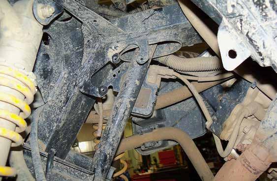
 Bolts securing Module Support also secure Steering Stem to Frame. See Fig. 7. 8.")
4 Removal: Keep all components removed from machine. 1. Raise front of machine, secure with jack stands, and remove Wheels. 2. Remove Inner Fenders and Intake. See Figs. 1-1a. 3. Remove Tie Rods from Steering Stem. See Fig Remove Castle Nut and Cotter Pin from Steering Stem. See Fig Remove hardware from Steering Stem as shown in Fig If necessary, unplug wiring harness and move wiring aside as shown in Fig. 5. Remove Control Module. See Fig. 5a. 7. Remove Module Support. See Fig (2) Bolts securing Module Support also secure Steering Stem to Frame. See Fig From top of ATV, remove Steering Stem. Discard stock O-Rings. See Figs. 8-8a. Fig. 1 Remove Tie Rods Remove Inner Fenders Fig. 2 Fig. 1a Remove hardware Remove Intake Loosen Clamp Remove Castle Nut and Pin from Steering Stem Fig. 3 (removal illustrations continue on following pages) 4


5 Fig. 4 Remove From Steering Stem Remove Module Support Remove Bolts Steering Stem Fig. 6 Steering Stem Fig. 7 Fig. 5 Steering Stem Pull out Fig. 8 Remove Control Module Fig. 5a Fig. 8a 5
 and Mounting Bracket Support (C) around Frame and secure with M8 x 60mm Lg.")
 to Lower Steering Shaft (E) with provided hardware. See Figs. 5-5a. - Secure Motor Mount (A) to Mounting Bracket Support (C) with M8 x 25mm Lg. FHCS and M8 Nylock Nuts. See Figs. 5-5a. - Reconnect Tie Rods to Lower Steering Shaft (E) with stock hardware.")
6 Installation: Do not tighten hardware completely unless noted. 1. Install Motor Mount (A) to Motor (G) with M10 x 25mm Lg. FHCS. See Motor Shafts Detail and Fig Install Lower Steering Shaft (E) to machine. Secure with stock Castle Nut and Cotter Pin. See Figs. 2-2a. 3. Install Mounting Bracket Side Support (B) and Mounting Bracket Support (C) around Frame and secure with M8 x 60mm Lg. FHCS and M8 Nylock Nuts. See Figs. 3-3a. Note: Radiator Hose will go under Mounting Brackets. 4. Install stock Upper Column Attachments to Upper Steering Shaft (F). See Figs. 4-4a. 5. Install Motor (G) to Lower Steering Shaft (E) with provided hardware. See Figs. 5-5a. - Secure Motor Mount (A) to Mounting Bracket Support (C) with M8 x 25mm Lg. FHCS and M8 Nylock Nuts. See Figs. 5-5a. - Reconnect Tie Rods to Lower Steering Shaft (E) with stock hardware. See Fig. 5a. 6. From top of machine insert Upper Shaft (F) and secure to Motor (G) with provided hardware. See Fig. 5a. - Secure Module Support, Column Attachment, and Upper Steering Shaft (F) to Frame with stock hardware. See Figs. 6-6a. 7. Remove Nuts from Exhaust Flange, install Heat Shield (K), and replace Nuts. See Fig Go to Page 12 for ECU Mounting on MAX models only - 8. Assemble ECU (H) to ECU Mount (D) with M8 x 20mm Lg. FHCS. See Fig. 8a. 9. On Right Side, near where Gear Selector connects to Engine, remove hardware securing Fuel Tank and Protector to Frame. See Figs. 8-8a. 10. Install ECU Mount (D) and secure with stock hardware removed in Step 9. See Fig. 8a. 11. Plug in Wiring Harness (J) and make connections. See Wiring Details, pages Tighten all hardware completely and reverse applicable steps taken during Removal. Handlebar and Tie Rods to be inline before tightening hardware. Remove Upper Shaft (E) from Motor (G) and realign if necessary. Motor Shafts Detail To Upper Shaft To Lower Shaft 6
 G M10 x 25mm")


7 Fig. 1 Qty. (3) G M10 x 25mm Lg. FHCS A E Fig. 2 Fig. 2a E stock Castle Nut (installation illustrations continue on following pages) Cotter Pin 7


 F O-Rings F Fig.")
8 B Fig. 3 C M8 x 60mm Lg. FHCS Fig. 3a C M8 Nylock Nut Frame B Radiator Hose will go under Mounting Brackets (B)(C) Upper Column Attatchment (Stock) Apply grease Upper Column Attatchment (Stock) F O-Rings F Fig. 4 Fig. 4a 8
 G A Qty. (4) C M8 Nut Fig.")

9 Fig. 5 M8 x 25mm Lg. FHCS Qty. (4) G A Qty. (4) C M8 Nut Fig. 5a F provided hardware E Install Tie Rods with stock hardware 9


, Fig.")

10 Fig. 6 Module Support Fig. 6a Column Attachment F F Stock Heat Shield (K), Fig. 7 Exhaust Flange K Stock Nuts Remove Nuts 10

 J Gear Selector D H Stock")
11 Fig. 8 Gear Selector Fuel Tank and Protector Fig. 8a M8 x 20mm Lg. FHCS Qty. (2) J Gear Selector D H Stock hardware Protector Frame 11

 and make connections. See Wiring Details, pages 13-14. J D H M8 x 20mm Lg.")
12 MAX Models ECU Mounting 1. Assemble ECU (H) to ECU Mount (D) with M8 x 25mm Lg. FHCS. 2. On Right Side, near where Gear Selector connects to Engine, remove Transmission Bolt. See below. 3. Install ECU Mount (D) and secure with stock hardware removed in Step Plug in Wiring Harness (J) and make connections. See Wiring Details, pages J D H M8 x 20mm Lg. FHCS Qty. (2) Stock Transmisson Bolt 12


 connects to Ground Lug.")
13 A ECU Functions Wiring Details Plug Function A B C D Motor Main Power and Ground Non-Contact Torque Sensor Key-On Power, Speed Sensor Wire, and LED When activated, LED Diagnostic Light will flash once for about 1 second before turning off indicating proper function. Should different patterns occur, contact SuperATV. B LED Diagnostic Light C D J Remove Voltage Regulator Cover Power Connections Secure in a visible location 1. Remove Voltage Regulator Cover. 2. Locate Starter Relay and Ground Lug. 3. Red Wire (positive) connects to Starter Relay post and Black Wire (ground) connects to Ground Lug. Rear Voltage Regulator Starter Relay Ground Lug Black Wire from Wire Harness (J) Battery Starter Relay Red Wire from Wire Harness (J) 13
 Red w/black Stripe Wire")

14 12V Source Connection (Left) (Right) Red w/black Stripe Wire (Left) (Right) Stock White Wire, Switched 12V Source from Wire Harness (J) 14

 from Wire Harness (L) to White Wire. See Figs.")

 connection. 15")
15 Speed Sensor Connection Soldering connection is recommended however, installer may use other forms of connecting. 1. Remove Panels shown in Fig. A and locate stock harness containing Red, Black, and White Wires. See Fig. B. 2. Solder, or use Scotch Lock, Blue Wire (Speed Sensor) from Wire Harness (L) to White Wire. See Figs. C - D. Remove Panels Fig. A Fig. B Right Side Soldering connection is recommended however, installer may use other forms of connecting. 1. Remove Panels shown in Fig. A and locate stock harness containing Red, Black, and White Wires. See Fig. B. 2. Solder, or use Scotch Lock, Blue Wire (Speed Sensor) from Wire Harness (L) to White Wire. See Figs. C - D. White Wire Fig. C J Blue Wire, Speed Sensor from Wire Harness (J) Fig. D Scotch Lock, or solder, White Wire to Blue Wire from Wire Harness (J) connection. 15
Thank You For Choosing. INSTALLATION INSTRUCTIONS Power Steering Kit: for Suzuki KingQuad. (kit contents continue on following page)
") 2753 Michigan Road Madison, Indiana 47250 855-743-3427 INSTALLATION INSTRUCTIONS Power Steering Kit: for Suzuki KingQuad Item F G H M Description ECU racket Lower Shaft Upper Shaft Mounting racket Wiring
2753 Michigan Road Madison, Indiana 47250 855-743-3427 INSTALLATION INSTRUCTIONS Power Steering Kit: for Suzuki KingQuad Item F G H M Description ECU racket Lower Shaft Upper Shaft Mounting racket Wiring
Thank You For Choosing. INSTALLATION INSTRUCTIONS Power Steering Kit for Polaris Ranger 570 B C. Need help with your installation?
 2753 Michigan Road Madison, Indiana 47250 855-743-3427 INSTALLATION INSTRUCTIONS Power Steering Kit for Polaris Ranger 570 Item A B C D E F G Description Motor Mount Upper Shaft Lower Shaft ECU Mount Connectors
Thank You For Choosing. INSTALLATION INSTRUCTIONS 3-5 Adjustable Lift Kit: for Polaris RZR XP (Passenger) (Driver)
 (Driver)") 2753 Michigan Road Madison, Indiana 47250 855-743-3427 INSTALLATION INSTRUCTIONS 3-5 Adjustable Lift Kit: for Polaris RZR XP 1000 Item Description Qty A Front Bracket 1 B Rear Bracket, Passenger 1 C Rear
2753 Michigan Road Madison, Indiana 47250 855-743-3427 INSTALLATION INSTRUCTIONS 3-5 Adjustable Lift Kit: for Polaris RZR XP 1000 Item Description Qty A Front Bracket 1 B Rear Bracket, Passenger 1 C Rear
See following page if provided Toggle Switch is being installed.
 2753 Michigan Road Madison, Indiana 47250 855-743-3427 INSTALLATION INSTRUCTIONS LED Wiring (LB3) Wire Harness To LED: Connect to plug on light. To Battery, Positive (+) Power: To Battery, Negative (-)
Verify, and adjust if necessary, centering of Rack and Pinion before installing.
 Verify, and adjust if necessary, centering of Rack and Pinion before installing. 1. Measure distance from inside of Rack and Pinion to face of Tie Rod End. 2. Measure distance from face of Tie Rod End
3 Lift Kit: for Polaris General
 INSTALLATION INSTRUCTIONS 2753 Michigan Road Madison, Indiana 47250 855-743-3427 3 Lift Kit: for Polaris General Item Description Qty A Rear Shock Bracket Brace 1 B Front Shock Bracket 1 C Rear Shock Bracket
Power Steering Kit: for Arctic Cat Wildcat Trail
 2753 Michigan Road Madison, Indiana 47250 855-743-3427 INSTLLTION INSTRUCTIONS Power Steering Kit: for rctic Cat Wildcat Trail Item B C D R S Description Motor Mount Stiffener Support Plate Upper Shaft
8:00am - 9:00pm EST M-Th 8:00am - 7:00pm EST Friday 9:00am - 2:00pm EST Saturday
 740 lifty rive Madison, Indiana 47250 812-574-7777 INSTALLATION INSTRUTIONS Power Steering Kit for Polaris Sportsman XP 850 3x M10 x 25mm Lg. FHS 6x M8 Nylock Nut Item A E escription EU Mount Motor Mount
Thank You For Choosing. INSTALLATION INSTRUCTIONS Power Steering Kit for Honda Pioneer 500. Need help with your installation?
 740B Clifty Drive Madison, Indiana 47250 812-574-7777 INSTALLATION INSTRUCTIONS Power Steering Kit for onda Pioneer 500 Item Description A Motor Mount B Support Plate C ECU Mount Item Description D Upper
Honda Pioneer Power Steering
 INSTALLATION INSTRUCTIONS 740B Clifty Drive Madison, Indiana 47250 812-574-7777 Honda Pioneer Power Steering Item Description Qty A Motor Mount 1 B Support Plate 1 C ECU Plate 1 Item Description Qty D
Honda Pioneer Lift Kit
 740B Clifty Drive Madison, Indiana 47250 812-574-7777 INSTALLATION INSTRUCTIONS Honda Pioneer Lift Kit Item Description Qty A Bracket 1 B Right Bracket 1 C Left Bracket 1 D Top Plates 2 E Radiator Reserve
Verify, and adjust if necessary, centering of Rack and Pinion before installing.
 Verify, and adjust if necessary, centering of before installing. measurement 1: face of Tie Rod End inside of 1. Measure distance from inside of Rack and Pinion to face of Tie Rod End. 2. Measure distance
6 Lift Kit - Kawasaki Teryx4
 2753 Michigan Road Madison, Indiana 47250 855-743-3427 INSTALLATION INSTRUCTIONS 6 Lift Kit - Kawasaki Teryx4 1 Spacers are required if running stock Wheels Driver C A D B Passenger Item Description A
Full Doors: for Honda Pioneer 1000 (2016+)
") INSTALLATION INSTRUCTIONS 2753 Michigan Road Madison, Indiana 47250 855-743-3427 Full Doors: for Honda Pioneer 1000 (2016+) A B Item A B Description Left Door Right Door Cleaning: - Do not use window cleaning
INSTALLATION INSTRUCTIONS 2753 Michigan Road Madison, Indiana 47250 855-743-3427 Full Doors: for Honda Pioneer 1000 (2016+) A B Item A B Description Left Door Right Door Cleaning: - Do not use window cleaning
Thank You For Choosing. INSTALLATION INSTRUCTIONS Power Steering Kit: for Bennche Bighorn 500/700. Need help with your installation?
 2753 Michigan Road Madison, Indiana 47250 855-743-3427 INSTLLTION INSTRUTIONS Power Steering Kit: for ennche ighorn 500/700 Item M S T escription Mounting racket Steering Shaft U-Joint Motor Mount Lockout
Nerf Bars: for Kawasaki Mule PRO-FXT
 INSTLLTION INSTRUTIONS 2753 Michigan Road Madison, Indiana 47250 855-743-3427 Item escription Front x 2 Right Rear Left Rear lamp x 2 E ap x 2 Nerf ars: for Kawasaki Mule PRO-FXT E 2x M12-1.75 x 30mm Lg.
Gen 2 Portal Gear Hubs for Polaris Ranger Crew 570/900
 2753 Michigan Road Madison, Indiana 47250 855-743-3427 INSTALLATION INSTRUCTIONS Gen 2 Portal Gear Hubs for Polaris Ranger Crew 570/900 A Item Description Qty A Rotor 4 B Gear Box, L 2 C Gear Box, R 2
Carrier Bearing. Thank You For Choosing INSTALLATION INSTRUCTIONS. (installation performed on Polaris RZR XP Turbo) Need help with your installation?
 Need help with your installation?") 2753 Michigan Road Madison, Indiana 47250 812-574-7777 INSTALLATION INSTRUCTIONS Carrier Bearing (installation performed on Polaris RZR XP Turbo) Read instructions and view illustrations before beginning.
2753 Michigan Road Madison, Indiana 47250 812-574-7777 INSTALLATION INSTRUCTIONS Carrier Bearing (installation performed on Polaris RZR XP Turbo) Read instructions and view illustrations before beginning.
3 Lift Kit: for Polaris General
 INSTALLATION INSTRUTIONS 740B lifty Drive Madison, Indiana 47250 812-574-7777 3 Lift Kit: for Polaris General Item Description Qty A Rear Shock Bracket Brace 1 B Shock Bracket 1 Rear Shock Bracket 2 D
Roof: for Honda Pioneer 1000
 2753 Michigan Road Madison, Indiana 47250 855-743-3427 INSTLLTION INSTRUTIONS Roof: for Honda Pioneer 1000 Remove Roof when trailering or secure with tie down straps. Item Description Front Rear enter
Yamaha Viking Lift Kit
 INSTLLTION INSTRUCTIONS 740 Clifty Drive Madison, Indiana 47250 812-574-7777 Yamaha Viking Lift Kit Item Description Qty Front racket Fore 1 Front racket ft 1 C Rear rackets 2 D Relocator racket 1 D C
Polaris RZR Power Steering
 740B Clifty rive Madison, Indiana 47250 812-574-7777 INSTLLTION INSTRUCTIONS Polaris RZR Power Steering Item escription Qty Motor Mount 1 B ECU Mount 1 C Support Bracket 1 Lower Shaft 1 E Upper Shaft 1
Flip Windshield: for Polaris Ranger 900
 INSTALLATION INSTRUCTIONS 2753 Michigan Road Madison, Indiana 47250 812-574-7777 Flip Windshield: for Polaris Ranger 900 Item A Description Windshield A Bulb Seal Read instructions and view illustrations
Thank You For Choosing. INSTALLATION INSTRUCTIONS Flip Windshield for Polaris General. Seal. Need help with your installation?
 2753 Michigan Road Madison, Indiana 47250 812-574-7777 INSTALLATION INSTRUCTIONS Flip Windshield for Polaris General A Item Description Qty A Windshield 1 Seal (kit contents continue on following pages)
Polaris RangerXP Power Steering
 740 lifty rive Madison, Indiana 47250 812-574-7777 INSTLLTION INSTRUTIONS Polaris RangerXP Power Steering Item N escription Mounting racket Lower Shaft Steering Shaft U racket 3x M8 x 20mm Lg. FHS 2x M6
Thank You For Choosing. INSTALLATION INSTRUCTIONS High Clearance Front A-Arms for Honda Pioneer 1000
 740 Clifty Drive Madison, Indiana 47250 812-574-7777 INSTLLTION INSTRUCTIONS High Clearance Front -rms for Honda Pioneer 1000 Item C D Description Upper -rm, Passenger Lower -rm, Passenger Upper -rm, Driver
Thank You For Choosing. INSTALLATION INSTRUCTIONS Snow Plow Mount for John Deere Gator C E G. Need help with your installation?
 740B Clifty Drive Madison, Indiana 47250 812-574-7777 INSTLLTION INSTRUCTIONS Snow Plow Mount for John Deere Gator Item Description Qty Mount Plate 1 B Front Bar 1 C Roller Bracket, L 1 Item Description
Thank You For Choosing. INSTALLATION INSTRUCTIONS Deluxe Plug and Play Turn Signal Kit Polaris General. Need help with your installation?
 2753 Michigan Road Madison, Indiana 47250 855-743-3427 INSTALLATION INSTRUCTIONS Deluxe Plug and Play Turn Signal Kit Polaris General Flasher Wiring Harness Horn Hose Clamp 1x Indicator Light 6x 10x Wire
Thank You For Choosing. INSTALLATION INSTRUCTIONS Flip Windshield for Kawasaki Mule FXT. Gasket. Hood Seal. Need help with your installation?
 740 Clifty Drive Madison, Indiana 47250 812-574-7777 INSTLLTION INSTRUCTIONS lip Windshield for Kawasaki Mule XT Item Description Upper Windshield Lower Windshield Gasket Hood Seal - When assembling, do
Max Clearance Honda Front Lower Arched Control Arm Kit
 780 Professional Drive N. Shreveport, LA 71105 Phone (318)-524-2270 Fax (318)-524-2297 Max Clearance Honda Front Lower Arched Control Arm Kit Read before Installation This product is designed for use on
780 Professional Drive N. Shreveport, LA Phone (318) Fax (318) Lift Kit Installation Instructions
 Fax (318) Lift Kit Installation Instructions") 780 Professional Drive N. Shreveport, LA 71105 Phone (318)-524-2270 Fax (318)-524-2297 www.highlifter.com Polaris Mid-Size 570 RANGER Models Lift Kit Installation Instructions Read before Installation
780 Professional Drive N. Shreveport, LA 71105 Phone (318)-524-2270 Fax (318)-524-2297 www.highlifter.com Polaris Mid-Size 570 RANGER Models Lift Kit Installation Instructions Read before Installation
Max Clearance Polaris RZR 900 S 60 Rear Lower Arched Control Arm Kit
 780 Professional Drive N. Shreveport, LA 71105 Phone (318)-524-2270 Fax (318)-524-2297 Max Clearance Polaris RZR 900 S 60 Rear Lower Arched Control Arm Kit Read before Installation This product is designed
4. Remove the cotter pin that secures the castle nut to the axle. Once you have done this remove the castle nut and pull off the hub/rotor assembly.
 780 Professional Drive N. Shreveport, LA 71105 Phone (318)-524-2270 Fax (318)-524-2297 Max Clearance Honda Pioneer 1000 Front Forward Arched Control Arm Kit Read before Installation This product is designed
2. Remove front wheels.
 1 PARTS DIAGRAM 2 Installation Instructions: (PASSENGER SIDE) 1. Place jack under center of RUV front end and lift until front wheels clear the ground. Be careful to support the RUV properly so that it
Max Clearance Polaris Sportsman Arched A-arm Kit
 780 Professional Drive N. Shreveport, LA 71105 Phone (318)-524-2270 Fax (318)-524-2297 Max Clearance Polaris Sportsman Arched A-arm Kit Read before Installation This product is designed for use on ATVs
FRONT LIFT INSTALLATION *When referring to left and right positions during the installation process, it is from the seated position*
 1 Parts Diagram 2 FRONT LIFT INSTALLATION *When referring to left and right positions during the installation process, it is from the seated position* 1. Place UTV transmission in park. Place jack under
780 Professional Drive N. Shreveport, LA Phone (318) Fax (318) Lift Kit Installation Instructions
 Fax (318) Lift Kit Installation Instructions") 780 Professional Drive N. Shreveport, LA 71105 Phone (318)-524-2270 Fax (318)-524-2297 Yamaha Grizzly 700 Lift Kit Lift Kit Installation Instructions Read before Installation This product is designed for
780 Professional Drive N. Shreveport, LA 71105 Phone (318)-524-2270 Fax (318)-524-2297 Yamaha Grizzly 700 Lift Kit Lift Kit Installation Instructions Read before Installation This product is designed for
780 Professional Drive N. Shreveport, LA Phone (318) Fax (318) Polaris RZR TURBO XP
 Fax (318) Polaris RZR TURBO XP") 780 Professional Drive N. Shreveport, LA 71105 Phone (318)-524-2270 Fax (318)-524-2297 www.highlifter.com Polaris RZR TURBO XP Read before Installation This product is designed for use on ATVs and/or RUVs
780 Professional Drive N. Shreveport, LA 71105 Phone (318)-524-2270 Fax (318)-524-2297 www.highlifter.com Polaris RZR TURBO XP Read before Installation This product is designed for use on ATVs and/or RUVs
780 Professional Dr. North, Shreveport, LA Polaris Ranger Lift Kit Installation Instructions CLKCMX3-02
 780 Professional Dr. North, Shreveport, LA. 318-524-2270 Polaris Ranger Lift Kit Installation Instructions CLKCMX3-02 Read before Installation This product is designed for use on ATVs and/or RUVs to increase
780 Professional Drive N. Shreveport, LA Phone (318) Fax (318)
 Fax (318)") 780 Professional Drive N. Shreveport, LA 71105 Phone (318)-524-2270 Fax (318)-524-2297 Yamaha YXZ 1000 Lift Kit Installation Instructions Read before Installation This product is designed for use on ATVs
780 Professional Drive N. Shreveport, LA 71105 Phone (318)-524-2270 Fax (318)-524-2297 Yamaha YXZ 1000 Lift Kit Installation Instructions Read before Installation This product is designed for use on ATVs
780 Professional Drive N. Shreveport, LA Phone (318) Fax (318) Honda 420 Installation Instructions
 Fax (318) Honda 420 Installation Instructions") 780 Professional Drive N. Shreveport, LA 71105 Phone (318)-524-2270 Fax (318)-524-2297 www.highlifter.com Honda 420 Installation Instructions Read before Installation This product is designed for use on
780 Professional Drive N. Shreveport, LA 71105 Phone (318)-524-2270 Fax (318)-524-2297 www.highlifter.com Honda 420 Installation Instructions Read before Installation This product is designed for use on
NOTE: IF RUNNING FACTORY RANGER 900 ALUMINUM WHEELS OR AFTERMARKET ALUMINUM WHEELS THEN SPACERS ARE NOT REQUIRED.
 780 Professional Dr. North, Shreveport, LA. 318-524-2270 Polaris 900 XP Ranger Lift Kit Installation Instructions Read before Installation This product is designed for use on ATVs and/or RUVs to increase
780 Professional Drive N Shreveport, LA Phone (318) Polaris Ranger RZR 1000 XP Upper Radius Bars
 Polaris Ranger RZR 1000 XP Upper Radius Bars") 780 Professional Drive N Shreveport, LA 71105 Phone (318)524-2270 Polaris Ranger RZR 1000 XP Upper Radius Bars Read before Installation This product is designed for use on ATVs and/or RUVs to increase
780 Professional Drive N Shreveport, LA 71105 Phone (318)524-2270 Polaris Ranger RZR 1000 XP Upper Radius Bars Read before Installation This product is designed for use on ATVs and/or RUVs to increase
780 Professional Drive N. Shreveport, LA Phone (318) Fax (318) KLKM
 Fax (318) KLKM") 780 Professional Drive N. Shreveport, LA 71105 Phone (318)-524-2270 Fax (318)-524-2297 www.highlifter.com KLKM3000-00 Read before Installation This product is designed for use on ATVs and/or RUVs to increase
780 Professional Drive N. Shreveport, LA 71105 Phone (318)-524-2270 Fax (318)-524-2297 www.highlifter.com KLKM3000-00 Read before Installation This product is designed for use on ATVs and/or RUVs to increase
780 Professional Drive N. Shreveport, LA Phone (318) Fax (318) Suzuki King Quad 750/500Lift Kit Installation Instructions
 Fax (318) Suzuki King Quad 750/500Lift Kit Installation Instructions") 780 Professional Drive N. Shreveport, LA 71105 Phone (318)-524-2270 Fax (318)-524-2297 Suzuki King Quad 750/500Lift Kit Installation Instructions Read before Installation This product is designed for use
780 Professional Drive N. Shreveport, LA 71105 Phone (318)-524-2270 Fax (318)-524-2297 Suzuki King Quad 750/500Lift Kit Installation Instructions Read before Installation This product is designed for use
Polaris Ranger RZR 1000 XP Radius Bars PSRA-RZR1
 780 Professional Drive N Shreveport, LA 71105 Phone (318)524-2270 Polaris Ranger RZR 1000 XP Radius Bars PSRA-RZR1 Read before Installation This product is designed for use on ATVs and/or RUVs to increase
780 Professional Drive N. Shreveport, LA Phone (318) Fax (318) Kawasaki Mule Pro FXT
 Fax (318) Kawasaki Mule Pro FXT") 780 Professional Drive N. Shreveport, LA 71105 Phone (318)-524-2270 Fax (318)-524-2297 www.highlifter.com Kawasaki Mule Pro FXT Read before Installation This product is designed for use on ATVs and/or
780 Professional Drive N. Shreveport, LA 71105 Phone (318)-524-2270 Fax (318)-524-2297 www.highlifter.com Kawasaki Mule Pro FXT Read before Installation This product is designed for use on ATVs and/or
780 Professional Drive N. Shreveport, LA Phone (318) Fax (318)
 Fax (318)") 780 Professional Drive N. Shreveport, LA 71105 Phone (318)-524-2270 Fax (318)-524-2297 www.highlifter.com Polaris RZR 570 Lift Kit Installation Instructions Read before Installation This product is designed
780 Professional Drive N. Shreveport, LA 71105 Phone (318)-524-2270 Fax (318)-524-2297 www.highlifter.com Polaris RZR 570 Lift Kit Installation Instructions Read before Installation This product is designed
780 Professional Drive N. Shreveport, LA Phone (318) Fax (318) Honda Lift Kit Installation Instructions
 Fax (318) Honda Lift Kit Installation Instructions") 780 Professional Drive N. Shreveport, LA 71105 Phone (318)-524-2270 Fax (318)-524-2297 www.highlifter.com Honda Lift Kit Installation Instructions Read before Installation This product is designed for
780 Professional Drive N. Shreveport, LA 71105 Phone (318)-524-2270 Fax (318)-524-2297 www.highlifter.com Honda Lift Kit Installation Instructions Read before Installation This product is designed for
Honda 700 Pioneer Lift Kit
 780 Professional Drive N. Shreveport, LA 71105 Phone (318)-524-2270 Fax (318)-524-2297 www.highlifter.com Honda 700 Pioneer Lift Kit Read before Installation This product is designed for use on ATVs and/or
780 Professional Drive N. Shreveport, LA Phone (318) Fax (318)
 Fax (318)") 780 Professional Drive N. Shreveport, LA 71105 Phone (318)-524-2270 Fax (318)-524-2297 www.highlifter.com KLKM610-00 Read before Installation This product is designed for use on ATVs and/or RUVs to increase
780 Professional Drive N. Shreveport, LA 71105 Phone (318)-524-2270 Fax (318)-524-2297 www.highlifter.com KLKM610-00 Read before Installation This product is designed for use on ATVs and/or RUVs to increase
NOTE: IF RUNNING FACTORY RANGER ALUMINUM WHEELS OR AFTERMARKET ALUMINUM WHEELS THEN SPACERS ARE NOT REQUIRED.
 780 Professional Dr. North, Shreveport, LA. 318-524-2270 Polaris Ranger Lift Kit Installation Instructions PLK1000R-51 Read before Installation This product is designed for use on ATVs and/or RUVs to increase
SPORTSMAN 800/500 INSTALLATION NOTES FOR 2011 MODELS:
 780 Professional Drive N Shreveport, LA 71105 Phone: 318-524-2270 Polaris Sportsman Lift Kit Read before Installation This product is designed for use on ATVs and/or RUVs to increase ground clearance and
(318) (318) & 800 RANGER IRS
 (318) & 800 RANGER IRS") 780 Professional Drive N. Shreveport, LA 71105 Phone (318)-524-2270 Fax (318)-524-2297 Polaris 700 & 800 RANGER IRS Models Lift Kit Installation Instructions Read before Installation This product is designed
780 Professional Drive N. Shreveport, LA 71105 Phone (318)-524-2270 Fax (318)-524-2297 Polaris 700 & 800 RANGER IRS Models Lift Kit Installation Instructions Read before Installation This product is designed
Suzuki 500 (98+) Lift Kit Installation Instructions
 Lift Kit Installation Instructions") 780 Professional Drive N. Shreveport, LA 71105 Phone (318)-524-2270 Fax (318)-524-2297 www.highlifter.com Suzuki 500 (98+) Lift Kit Installation Instructions Read before Installation This product is designed
780 Professional Drive N. Shreveport, LA 71105 Phone (318)-524-2270 Fax (318)-524-2297 www.highlifter.com Suzuki 500 (98+) Lift Kit Installation Instructions Read before Installation This product is designed
780 Professional Drive N. Shreveport, LA Phone (318) Fax (318) Kawasaki Teryx 4-Seater
 Fax (318) Kawasaki Teryx 4-Seater") 780 Professional Drive N. Shreveport, LA 71105 Phone (318)-524-2270 Fax (318)-524-2297 Kawasaki Teryx 4-Seater Read before Installation This product is designed for use on ATVs and/or RUVs to increase
780 Professional Drive N. Shreveport, LA 71105 Phone (318)-524-2270 Fax (318)-524-2297 Kawasaki Teryx 4-Seater Read before Installation This product is designed for use on ATVs and/or RUVs to increase
It is your responsibility to always inform other operators and passengers of this vehicle and about the added risks.
 780 Professional Drive N. Shreveport, LA 71105 Phone (318)-524-2270 Fax (318)-524-2297 www.highlifter.com Read before Installation This product is designed for use on RUVs for extreme mud riding conditions.
INSTALLATION INSTRUCTIONS *When referring to left and right positions during the installation process, it is from the seated position*
 1 PARTS DIAGRAMS 2 3 4 INSTALLATION INSTRUCTIONS *When referring to left and right positions during the installation process, it is from the seated position* FRONT LIFT INSTALLATION 1. Place a jack under
This lift allows you to convert from lifted to unlifted positions!
 780 Professional Drive N. Shreveport, LA 71105 Phone (318)-524-2270 Fax (318)-524-2297 Polaris Ranger RZR 900 XP This lift allows you to convert from lifted to unlifted positions! Read Before Installation
Arctic Cat Wild Cat Upper Radius Bars
 780 Professional Drive N Shreveport, LA 71105 Phone (318)524-2270 Arctic Cat Wild Cat Upper Radius Bars Read Before Installation This product is designed for use on ATVs and/or RUVs to increase ground
INSTALL GUIDE Dodge/RAM 5.7L HEMI
 INSTALL GUIDE 2009-2017 Dodge/RAM 5.7L HEMI TABLE OF CONTENTS 3 GETTING STARTED 3 PARTS LIST 4 INSTALLATION INSTRUCTIONS 4 REMOVING THE STOCK INTAKE ASSEMBLY 6 INSTALLING THE AIR FILTER 7 INSTALLING THE
It is your responsibility to always inform other operators and passengers of this vehicle and about the added risks.
 780 Professional Drive N. Shreveport, LA 71105 Phone (318)-524-2270 Fax (318)-524-2297 www.highlifter.com Read before Installation This product is designed for use on ATVs and/or RUVs for extreme mud riding
Polaris RZR 900 XP Arched Trailing Arms PSATA-RZR9
 780 Professional Drive N Shreveport, LA 71105 Phone (318)524-2270 Polaris RZR 900 XP Arched Trailing Arms PSATA-RZR9 Read Before Installation This product is designed for use on ATVs and/or RUVs to increase
780 Professional Drive N. Shreveport, LA Phone (318) Fax (318)
 Fax (318)") 780 Professional Drive N. Shreveport, LA 71105 Phone (318)-524-2270 Fax (318)-524-2297 Read before Installation This product is designed for use on ATVs and/or RUVs for extreme mud riding conditions. Purchasers
780 Professional Drive N. Shreveport, LA 71105 Phone (318)-524-2270 Fax (318)-524-2297 Read before Installation This product is designed for use on ATVs and/or RUVs for extreme mud riding conditions. Purchasers
BEFORE YOU BEGIN LIST OF COMPONENTS. Isopropyl SWITCH SCOTCH-BRITE PAD ALCOHOL PREP PAD SWITCH HARNESS REVOLVER PCM COVER STICKER
 User Manual TABLE OF CONTENTS BEFORE YOU BEGIN...3 LIST OF COMPONENTS... 3 REVOLVER INSTALLATION 95-97 Trucks...4 REVOLVER INSTALLATION 98-03 Trucks...7 SWITCH INSTALLATION...12 SAFETY WARNING & CAUTION...14
Dfuser T/C Lock-Un Lock
 Dfuser T/C Lock-Un Lock Performance Diesel and more! For more information visit our website at: http://www.dfuser.com Page 1 of 6 User Guide This harness overrides and monitors Torque Converter (T/C) lockup
Forbidden Diesel Performance Ford 6.7L Powerstroke EGR Delete Instructions 6.7L EGR DELETE BY FORBIDDEN DIESEL PERFORMANCE. Page 1
 6.7L EGR DELETE BY FORBIDDEN DIESEL PERFORMANCE Page 1 WARNING REGARDING EMISSIONS LAWS Not legal for sale or use on pollution-controlled motor vehicles anywhere in the United States. Legal ONLY for off-road
It is your responsibility to always inform other operators and passengers of this vehicle and about the added risks.
 780 Professional Drive N. Shreveport, LA 71105 Phone (318)-524-2270 Fax (318)-524-2297 www.highlifter.com Read before Installation This product is designed for use on RUVs for extreme mud riding conditions.
Ford 7.3L SuperDuty Cold Air Intake
 999.5-2003 Ford 7.3L SuperDuty Cold Air Intake ! DISCLAIMER ) By installing this product onto your vehicle, you assume all risk and liability associated with its use. 2) It is your responsibility to make
Installation Manual. Upper Control Arms W/Uniball joint Toyota Tacoma 4wd & 2wd PreRunner. Part # Part # 50930
 Installation Manual Upper Control Arms W/Uniball joint 2005-2016 Toyota Tacoma 4wd & 2wd PreRunner Part # 50930 SS08182014 Part # 50930 Upper Control Arms W/Uniball joint 2005-2016 Toyota Tacoma 4wd &
2 Strut Spacer / Preload Lift. Ford Ranger 4wd Part#:
 Part#: 013203 2 Strut Spacer / Preload Lift Ford Ranger 4wd 2019 Rev. 022119 491 W. Garfield Ave., Coldwater, MI 49036. Phone: 517-279-2135 Web: www.bds-suspension.com. E-mail: tech-bds@ridefox.com Read
INSTALLATION INSTRUCTIONS PART NUMBER:
 Equipped with AEM Dryflow Filter No Oil Required! INSTALLATION INSTRUCTIONS PART NUMBER: 41-1406 2006-2013 LEXUS IS250 V6-2.5L LEGAL IN CALIFORNIA ONLY FOR RACING VEHICLES WHICH MAY NEVER BE USED, REGISTERED
SPECIAL TOOLS REQUIRED:
 INSTALLATION INSTRUCTIONS FOR 2010-15 TOYOTA 4RUNNER WITH XREAS SUSPENSION 3 SUSPENSION LIFT KIT PART NUMBER 432X WARNING!!! READ AND UNDERSTAND ALL INSTRUCTIONS BEFORE PROCEEDING. MAKE SURE THAT YOU HAVE
Installation Manual Ram x4 4 Lift w/upper control arms. Part # Part # 34105
 Installation Manual 2009 2018 Ram 1500 4x4 4 Lift w/upper control arms Part # 34105 ss09172014 Part # 34105 2009-2018 Ram 1500 4x4 4 suspension system w/upper control arms Part # Description Qty. 34105-01
INSTALLATION INSTRUCTIONS
 INSTALLATION INSTRUCTIONS ROCKSTAR SOFTAIL MINIMUM REQUIRED TOOLS: FLAT HEAD SCREWDRIVER 1/2, 9/16, 14mm, 7/8 or 22mm WRENCHES 5/16, 1/2, 9/16 SOCKETS AND RATCHET SNAP RING PILERS 3/16, 1/4, 5/16 ALLEN
Suzuki 700 Lift Kit Lift Kit Installation Instructions
 High Lifter Products, Inc. 318-524-2270 780 N Professional Drive 318-524-2297 Shreveport, LA 71105 Suzuki 700 Lift Kit Lift Kit Installation Instructions Read Before Installation This product is designed
COLD AIR INTAKE SYSTEM, CIVIC Si,
 COLD AIR INTAKE SYSTEM, CIVIC Si, 2012+ 343-05-0200 PLEASE READ CAREFULLY BEFORE PROCEEDING WITH INSTALL Parts list (Please verify all parts are included in the kit before proceeding with installation)
INSTALL GUIDE Silverado/Sierra L/6.2L
 INSTALL GUIDE 2014-2017 Silverado/Sierra 1500 5.3L/6.2L TABLE OF CONTENTS 3 GETTING STARTED 3 PARTS LIST 4 INSTALLATION INSTRUCTIONS 4 REMOVING THE STOCK INTAKE ASSEMBLY 7 INSTALLING THE AIR FILTER 8 INSTALLING
Installation manual 3 suspension system Toyota Tacoma 4 x 4 & PreRunner Part # sj rev.03
 Part #: 52904 1995-2004 Toyota Tacoma 4 x 4 & PreRunner 3 suspension system Parts list: Part # Description Qty. 52904-01 Rear brake proportioning valve bracket 1 52907-02 Front pre load spacer 2 52904-03
INSTALLATION INSTRUCTIONS
 MINIMUM REQUIRED TOOLS: INSTALLATION INSTRUCTIONS ROCKSTAR TOURING FLAT HEAD SCREWDRIVER 1/2, 9/16, 14mm, 7/8 or 22mm WRENCHES 5/16, 1/2, 9/16 SOCKETS AND RATCHET SNAP RING PILERS 3/16, 1/4, 5/16 ALLEN
Installation manual 2 Leveling kit GM x 4. Part # Part # Important customer information: GM x 4
 Installation manual 2 Leveling kit 2007-2008 GM 1500 4 x 4 Part # 12000 sj121007rev.02 Part # 12000 2007-2008 GM 1500 4 x 4 2 leveling system Parts list: Part # Description Qty. 12000-01 Front leveling
Installation Manual. Uniball Upper Control Arm Kit Toyota Tacoma 4x Toyota 4Runner 4x Toyota Tundra 4x4 Part # 50965
 Part # 50965 Uniball upper control arm kit Part # Description Qty. 50965-01 Driver side upper control arm 1 50965-02 Passenger side upper control arm 1 50965-03 Driver side knuckle support bracket 1 50965-04
INSTALLATION MANUAL TOYOTA TUNDRA 5 SUSPENSION SYSTEM PART # 55905
 PART NUMBER : 55905 1999 2003 TOYOTA TUNDRA 5 SUSPENSION SYSTEM PARTS LIST: Part # Description Qty. 55900-01 Driver Side Spindle 1 55900-02 Passenger Side Spindle 1 55905-03 Rear brake proportioning valve
Dfuser T/C Lock Override with LED
 Dfuser T/C Lock Override with LED the bug that has no cure For more information visit our website at: http://www.dfuser.com Page 1 of 7 User Guide This harness overrides and monitors Torque Converter (T/C)
FRONT DRIVELINE MODIFICATION MAY BE NECESSARY!!!!
 INSTALLATION INSTRUCTIONS FOR 2009 DODGE 2500/3500 4WD & 1500 Mega Cab 6 SUSPENSION SYSTEM PART NUMBER 7206 Requires the following parts (sold separately) for a complete installation: Front Coil Spring
Harley Davidson FL Touring Current Xtreme
 ITEMS SUPPLIED Description Part # Qty Front Header (Chr/Blk) 100-0119/100-0123 1 Rear Header (Chr/Blk) 100-0120/100-0124 1 Front Heat Shield (Chr/Blk) 100-0121/100-0125 1 Rear Heat Shield (Chr/Blk) 100-0122/100-0126
Installation manual 3 front / 2 rear suspension system FJ / Runner Part # sj110607rev.03
 Part #: 52000 2007-2014 Toyota FJ / 2003-2009 4Runner 3 front / 2 rear suspension system Parts list: Part # Description Qty. 52907-01 Pre load spacer 2 52907-02 Strut spacer 2 MO3531BK-01 Rear coil spring
Tacoma Front Suspension Install Instructions
 1995-04 Tacoma Front Suspension Install Instructions Important notices: These instructions are intended only as a general guide for installing All-Pro products. For some items, specialized mechanical skills,
INSTALLATION INSTRUCTIONS
 Equipped with AEM Dryflow Filter No Oil Required! INSTALLATION INSTRUCTIONS PART NUMBER: 22-474 2007 SUBARU Impreza WRX STi H4-2.5L SEE * NOTE 2004-2006 SUBARU Impreza WRX STi H4-2.5L C.A.R.B. E.O. # D-670
INSTALLATION INSTRUCTIONS FOR FORD 4WD SUPER DUTY 2-1/2 SUSPENSION SYSTEM
 INSTALLATION INSTRUCTIONS FOR 1999-2004 FORD 4WD SUPER DUTY 2-1/2 SUSPENSION SYSTEM Requires the following parts for a complete installation: Front Leaf Springs P/N 60SD25 Vehicle specific Box Kit depending
KIT # MC-2992, MC-2993 INDIAN SCOUT SERIES W/ ABS 2014-PRESENT
 Congratulations on your purchase of an Arnott Motorcycle Air Suspension system. This system provides you with the ability to maintain your bike at a constant level regardless of load, resulting in enhanced
Dfuser Eighteen-K Plus Power Module the bug that has no cure
 Dfuser Eighteen-K Plus Power Module the bug that has no cure Copyright 2004, 2005, 2006 dfuser.com, LLC. All rights reserved. Page 1 of 6 User Guide What Known as the 18K module, this device is designed
INSTALL GUIDE Ford F L
 INSTALL GUIDE 2011-2014 Ford F-150 5.0L TABLE OF CONTENTS 3 GETTING STARTED 3 PARTS LIST 4 INSTALLATION INSTRUCTIONS 4 REMOVING THE STOCK INTAKE ASSEMBLY 5 INSTALLING THE AIR FILTER 6 INSTALLING THE HOUSING
Installation manual. 4 suspension system Chevy or GMC WD. Part # Part # Important customer information:
 Installation manual 4 suspension system 2014-2018 Chevy or GMC 1500 4WD Part # 14059 sj09052013rev.01 Part # 14059 2014-2018 Chevy or GMC 1500 4WD 4 suspension system Part # Description Qty. 14056-01 Upper
INSTALLATION INSTRUCTIONS PART NUMBER:
 Equipped with AEM Dryflow Filter No Oil Required! INSTALLATION INSTRUCTIONS PART NUMBER: 22-474 2006-2007 SUBARU Impreza WRX H4-2.5L C.A.R.B. E.O. # D-670-6 2004-2007 SUBARU Impreza WRX STi H4-2.5L C.A.R.B.
Installation manual. Toyota Tundra 4WD & 2WD. 2.5 Suspension kit. Part # Part # Important customer information:
 Installation manual 2007-2016 Toyota Tundra 4WD & 2WD 2.5 Suspension kit Part # 53070 sj11082011rev.03 Part # 53070 2007-2016 Toyota Tundra 4WD & 2WD 2.5 Suspension kit Part # Description Qty. 53070-01
INSTALLATION INSTRUCTIONS
 INSTALLATION INSTRUCTIONS RIOT DYNA MINIMUM REQUIRED TOOLS: FLAT HEAD SCREWDRIVER 1/2, 9/16, 14mm, 7/8 or 22mm WRENCHES 5/16, 1/2, 9/16 SOCKETS AND RATCHET SNAP RING PILERS 3/16, 1/4, 5/16 ALLEN WRENCH
S&S. Installation Instructions for S&S VFI Knock Sensor Kit for 2001-'07 Delphi Style VFI Module (with USB) Instruction
 Instruction") Instruction 106-1544 9-28-07 Copyright 2007 by S&S Cycle, Inc. All rights reserved. Printed in the U.S.A. S&S Cycle, Inc. 235 Causeway Blvd. La Crosse, Wisconsin 54603 Phone: 608-627-1497 Fax: 608-627-1488
Instruction 106-1544 9-28-07 Copyright 2007 by S&S Cycle, Inc. All rights reserved. Printed in the U.S.A. S&S Cycle, Inc. 235 Causeway Blvd. La Crosse, Wisconsin 54603 Phone: 608-627-1497 Fax: 608-627-1488
INSTALLATION INSTRUCTIONS
 MINIMUM REQUIRED TOOLS: INSTALLATION INSTRUCTIONS BANDIT SPORTSTER FLAT HEAD SCREWDRIVER 1/2, 9/16, 14mm, 7/8 or 22mm WRENCHES 5/16, 1/2, 9/16 SOCKETS AND RATCHET SNAP RING PILERS 3/16, 1/4, 5/16 ALLEN
*1272BAG8* 1272BAG CHEVY/GM & 6 NTD DROP LIFT KIT A
 921272200A 99-06 CHEVY/GM 1500 4 & 6 NTD DROP LIFT KIT Thank you for choosing Rough Country for all of your suspension needs. Rough Country recommends a certified technician installs this system. In addition