Service Manual. Fuller Heavy Duty Transmissions TRSM0250 October 2007
|
|
|
- Douglas Fletcher
- 5 years ago
- Views:
Transcription
1 Service Manual Fuller Heavy Duty Transmissions TRSM0250 October 2007
2
3 TABLE OF CONTENTS FOREWORD MODEL DESIGNATIONS AND SPECIFICATIONS LUBRICATION OPERATION POWER FLOW TIMING TORQUE RECOMMENDATIONS TOOL REFERENCE PREVENTIVE MAINTENANCE PRECAUTIONS DISASSEMBLY INSPECTION REASSEMBLY CHANGING INPUT SHAFT DISASSEMBLY AND REASSEMBLY - SHIFTING CONTROLS GEAR SHIFT LEVER HOUSING ASSEMBLY. SHIFT BAR HOUSING ASSEMBLY REMOVAL - COMPANION FLANGE AND CLUTCH REMOVAL - REAR HOUSING DISASSEMBLY - REAR HOUSING DISASSEMBLY - FRONT SECTION REASSEMBLY - FRONT SECTION REASSEMBLY & INSTALLATION REAR HOUSING INSTALLATION - COMPANION FLANGE AND CLUTCH HOUSING INSTALLATION - SHIFTING CONTROLS SHIFT BAR HOUSING ASSEMBLY GEAR SHIFT LEVER HOUSING ASSEMBLY
4 FOREWORD This manual is designed to provide detailed information necessary to service and repair the Fuller Transmissions listed on the cover. As outlined in the Table of Contents, the manual is divided into 3 main sections: a. Technical information and reference b. Removal, disassembly, reassembly and installation c. Options The format of the manual is designed to be followed in its entirety if complete disassembly and reassembly of the transmission is necessary. But if only one component of the transmission needs to be repaired, refer to the Table of Contents for the page numbers showing that component. For example, if you need to work on the Shift Bar Housing, you will find instructions for removal, disassembly and reassembly on page 21. Instructions for installation are on page 76. Service Manuals, Illustrated Parts Lists, Drivers Instructions, Driver Training Programs and other forms of product service information for these and other Fuller Transmissions are available upon request. A Technical Literature Order Form may be found in the back of this manual*. You may also obtain Service Bulletins, detailing information on product improvements, repair procedures and other service-related subjects by writing to the following address: EATON CORPORATION TRANSMISSION DIVISION Technical Service Department P.O. Box 4013 Kalamazoo, Michigan (61 6) Every effort has been made to ensure the accuracy of all information in this brochure. However, Eaton Transmission Division makes no expressed or implied warranty or representation based on the enclosed information. Any errors or omissions may be reported to Marketing Communications, Eaton Transmission Division, P.O. Box 4013, Kalamazoo, Ml
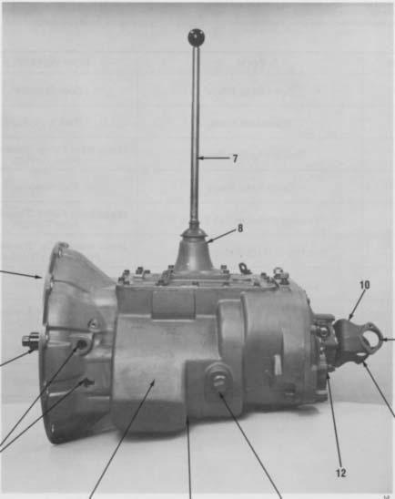
5 MODEL DESIGNATIONS AND SPECIFICATIONS Nomenclature: IMPORTANT: All Fuller Transmissions are identified by model and serial number. This information is stamped on the transmission identification tag and affixed to the case. DO NOT REMOVE OR DESTROY THE TRANS- MISSION IDENTIFICATION TAG. 7 Speed Series Transmissions See Chart Notes. CHART NOTES: 1 Lengths measured from face of clutch housing to front bottoming surface of companion flange or yoke. 2 Weights include SAE No. 1 cast iron clutch housing and standard controls (gear shift lever and housing assembly), less clutch release parts. For information on available clutch housings, refer to Publication FUL Clutch Housing Chart. All weights are approximate. 3 Oil Capacities are approximate, depending on inclination of engine and transmission. Always fill transmission with proper grade and type of lubricant to level of filler opening. See LUBRICATION.
6 LUBRICATION Proper Lubrication... the Key to long transmission life Proper lubrication procedures are the key to a good all-around maintenance program. If the oil is not doing its job, or if the oil level is ignored, all the maintenance procedures in the world are not going to keep the transmission running or assure long transmission life. Eaton Fuller Transmissions are designed so that the internal parts operate in a bath of oil circulated by the motion of gears and shafts. Thus, ail parts will be amply lubricated if these procedures are closely followed: 1. Maintain oil level. Inspect regularly. 2. Change oil regularly. 3. Use the correct grade and type of oil. 4. Buy from a reputable dealer. I I I I I I I I Lubrication Change and Inspection Eaton Roadranger CD50 Transmission Fluid HIGHWAY USE Heavy Duty and Mid-Range First 3,000 to 5,000 miles Factory fill (4827 to 8045 Km) Inltlal drain Every 10,000 miles Check fluid level (16090 Km) Check for leaks Heavy Duty Highway Change Interval Every 250,000 miles Change transmission ( Km) fluid, Mid-Range Highway Change Interval Every 100,000 miles (160,000 Km) Change transmission or every 3 years whichever occurs first fluid. First 30 hours Every 40 hours Every 500 hours Every 1,000 hours OFF-HIGHWAY USE Factory fill Initial drain, Inspect fluid level Check for leaks Change transmission fluid where severe dirt conditions exist. Change transmission fluid (Normal off-highway use), Heavy Duty Engine Lubricant or Mineral Gear Lubricant HIGHWAY USE First 3,000 to 5,000 miles Factory fill (4827 to 8045 Km) Initial drain. Every 10,000 miles Inspect Iubricant level, (16090 Km) Check for leaks, Every 50,000 miles Change transmission (80450 Km) lubricant, OFF-HIGHWAY USE First 30 hours Change transmission lubricant on new units Every 40 hours Inspect Iubricant level Check for leaks Every 500 hours Change transmission Iubricant where severe dirt conditions exist. Every 1,000 hours Change transmission Iubricant (Normal off-highway use), Change the oil filter when fluid or lubricant is changed. Type Recommended Grade (SAE) Lubricants Fahrenheit (Celsius) Ambient Temperature Eaton Roadranger CD50 Transmission Fluid 50 All Heavy Duty Engine 011 MI L-L-2104B C or D or 50 Above 10 o F(-12 o C.) API-SF or API-CD 40 Above 10 o F(-12 o C.) (Previous API designations 30 Below 10 o F(-12 o C.) acceptable) Mineral Gear 011 with rust 90 Above 10 o F(-12 o C.) and oxidation Inhibitor 80W Below 10 o F(-12 o C.) API-GL-1 The use of mild EP gear oil or multi-purpose gear oil is not recommended, but if these gear oils are used, be sure to adhere to the following limitations: Do not use mild EP gear oil or multi-purpose gear oil when operating temperatures are above 230 F (110 o C). Many of these gear oils, particularly 85W140, break down above 230 F and coat seals, bearings and gears with deposits that may cause premature failures. If these deposits are observed (especially a coating on seal areas causing oil leakage), change to Eaton Roadranger CD50 transmission fluid, heavy duty engine oil or mineral gear oil to assure maximum component life and to maintain your warranty with Eaton. (Also see Operating Temperatures.) Additives and friction modifiers are not recommended for use in Eaton Fuller transmissions. Proper Oil Level Make sure oil is level with filler opening. Because you can reach oil with your finger does not mean oil is at proper level. One inch of oil level is about one gallon of oil. Draining Oil Drain transmission while oil is warm. To drain oil remove the drain plug at bottom of case. Clean the drain plug before re-installing. Refilling Clean case around filler plug and remove plug from side of case. Fill transmission to the level of the filler opening. If transmission has two filler openings, fill to level of both openings. The exact amount of oil will depend on the transmission inclination and model. Do not over fill this will cause oil to be forced out of the transmission. When adding oil, types and brands of oil should not be mixed because of possible in- 4 compatibility.,....
7 LUBRICATION Operating Temperatures With Eaton Roadranger CD50 Transmission Fluid Heavy Duty Engine Oil and Mineral Oil The transmission should not be operated consistently at temperatures above 250 o F (120 o C). However, intermittent operating temperatures to 300 o F (149 o C) will not harm the transmission. Operating temperatures above 250 o F increase the lubricant s rate of oxidation and shorten its effective life. When the average operating temperature is above 250 o F, the transmission may require more frequent oil changes or external cooling. The following conditions in any combination can cause operating temperatures of over 250 o F: (1) operating consistently at slow speeds, (2) high ambient temperatures, (3) restricted air flow around transmission, (4) exhaust system too close to transmission, (5) high horsepower, overdrive operation. External oil coolers are available to reduce operating temperatures when the above conditions are encountered. Proper Lubrication Levels as Related to Transmission Installation Angles If the transmission operating angle is more than 12 degrees, improper lubrication can occur. The operating angle is the transmission mounting angle in the chassis plus the percent of upgrade (expressed in degrees). The chart below illustrates the safe percent of upgrade on which the transmission can be used with various chassis mounting angles. For example: if you have a 4 degree transmission mounting angle, then 8 degrees (or 14 percent of grade) is equal to the limit of 12 degrees. If you have a O degree mounting angle, the transmission can be operated on a 12 degree (21 percent) grade. Anytime the transmission operating angle of 12 degrees is exceeded for an extended period of time the transmission should be equipped with an oil pump or cooler kit to insure proper lubrication. Note on the chart the effect low oil levels can have on safe operating angles. Allowing the oil level to fall 1/2 below the filler plug hole reduces the degree of grade by approximately 3 degrees (5.5 percent). Proper Lubrication Levels are Essential! Transmission Oil Coolers are: Recommended With engines of 350 H.P. and above with overdrive transmissions Required With engines 399 H.P. and above with overdrive transmissions and GCW S over 90,000 lbs. With engines 399 H.P. and above and 1400 Lbs.-Ft. or greater torque With engines 450 H.P. and above With EP or Multipurpose Gear Oil Mild EP gear oil and multipurpose gear oil are not recommended when lubricant operating temperatures are above 230 F (110). In addition, transmission oil coolers are not recommended with these gear oils since the oil cooler materials may be attacked by these gear oils. The lower temperature limit and oil cooler restriction with these gear oils generally limit their success to milder applications. Transmission Mounting Angle Dotted line showing 2 Quarts Low is for reference only. Not recommended.
8 OPERATION Shift Lever Patterns The T transmissions have seven forward speeds and one reverse. All models are shifted as you would shift any non-synchronized manual transmission, following the simple 7-speed shift pattern. Always double-clutch when making lever shifts. The longer lever throw in 6th and 7th gear positions provide greater clutching tooth contact.

9 POWER FLOW The transmission must transfer the engine's power in terms of torque to the vehicle's rear wheels. Knowledge of what takes place in the transmission during torque transfer is essential when trouble-shooting and making repairs become necessary Torque from the engine is transferred to the transmission's input shaft. Splines of input shaft engage internal splines in hub of main drive gear. Torque is split between the two countershaft drive gears. Torque is delivered along both countershaft to countershaft gears of "engaged" mainshaft gear. The cross section view illustrates 1st speed gear engagement. Internal clutching teeth in hub of engaged mainshaft gear transfers torque to mainshaft through sliding clutch. Mainshaft transfers torque directly to output shaft st SPEED POWER FLOW
10 TIMING All Fuller Twin countershaft transmissions are timed at assembly. It is important that proper timing procedures are followed when reassembling the transmission. Timing assures that the countershaft gears will contact the mating mainshaft gears at exactly the same time, allowing mainshaft gears to center on the mainshaft and equally divide the load. Timing is a simple procedure of making the appropriate teeth of a gear set prior to installation and placing them in proper mesh while in the transmission. C. Meshing Marked Countershaft Drive Gear Teeth with Marked Main Drive Gear Teeth. 1. When installing the bearings on left countershaft, mesh the marked tooth of countershaft drive gear with either set or two marked teeth on the main drive gear. 2. Repeat the procedure when installing the bearings on right countershaft (after installing mainshaft assembly), using the remaining set of two marked teeth on the main drive gear to time assembly. A. Marking Countershaft Drive Gear Teeth 1. Prior to placing each countershaft assembly into case, mark the tooth located directly over the keyway of drive gear as shown. This tooth is stamped with an O to aid identification. A. TOOTH MARKED ON EACH COUNTERSHAFT DRIVE GEAR FOR TIMING PURPOSES C. DRIVE GEAR SET PROPERLY B. Marking Main Drive Gear Teeth. 1. Mark any two adjacent teeth on the main drive gear. 2. Mark the two adjacent teeth located directly opposite the first set marked on the main drive gear. As shown below, there should be an equal number of unmarked gear teeth on each side between the marked sets. B. TEETH MARKED ON MAIN DRIVE GEAR FOR TIMING PURPOSES
11 TORQUE RECOMMENDATIONS Correct torque application is extremely important to assure long transmission life and dependable performance. Over-tightening or under-tightening can result in a loose installation and, in many instances, eventually cause damage to transmission gears, shafts, and/or bearings. Use a torque wrench whenever possible to attain recommended lbs./ft. ratings. Do not torque capscrews dry.
12 TORQUE RECOMMENDATIONS
13 TOOL REFERENCE Some repair procedures pictured in this manual show The specialized tools listed below can be obtained the use of specialized tools. Their actual use is rec- from a tool supplier or made from dimensions as retransmission repair easier, ommended as they make quired by the individual user. Detailed Fuller Transmis- faster, and prevent costly damage to critical parts. sion Tool Prints are availabe upon request by writing. But for the most part, ordinary mechanic s tools Eaton Corporation such as socket wrenches, screwdrivers, etc., and Transmission Division other standard shop items such as a press, mauls and Technical Service Dept. soft bars are all that is needed to successfully disas- P.O. Box 4013 semble and reassemble any Fuller Transmission. Kalamazoo, Michigan PAGE TOOL HOW OBTAINED 2 5 Snap Ring Pliers Tool Supplier 3 9 Mainshaft Hook Tool Supplier 2 0 Tension Spring Driver Made from Fuller Transmission Print T Snap Ring Pliers Tool Supplier 38 Bearing Puller w/set Screw 50 Bearing Drivers (Flanged-End) Made from Fuller Transmission Print T Made from Fuller Transmission Print Series T-10842* 50 Countershaft Support Tool Tool Supplier 52 Input Shaft Nut Installer Made from Fuller Transmission Print T A 74 Torque Wrench, 1000 Lbs./Ft. Capacity Tool Supplier 5 1 Input Shaft Bearing Driver Tool Supplier *Dimensions necessary to determine specific tool number required.
14 PREVENTIVE MAINTENANCE
15 PREVENTIVE MAINTENANCE PREVENTIVE MAINTENANCE CHECK CHART CHECKS WITHOUT PARTIAL DISASSEMBLY OF CHASSIS OR CAB Clutch Housing Mounting a. Check all capscrews in bolt circle of clutch housing for looseness. Clutch Release Bearing (Not Shown) a. Remove hand hole cover and check radial and axial clearance in release bearing. b. Check relative position of thrust surface of release bearing with thrust sleeve on pushtype clutches. Clutch Pedal Shaft and Bores a. Pry upward on shafts to check wear. b. If excessive movement is found, remove clutch release mechanism and check bushings in bores and wear on shafts. Lubricant a. Change at specified service intervals. b. Use only the types and grades as recommended. See LUBRICATION. Filler and Drain Plugs a. Remove filler plugs and check level of lubricant at specified intervals. Tighten filler and drain plugs securely. Capscrews and Gaskets a. Check all capscrews, especially those on PTO covers and rear bearing covers for looseness which would cause oil leakage. See TORQUE RECOMMENDATIONS. b. Check PTO opening and rear bearing covers for oil leakage due to faulty gasket. Gear Shift Lever a. Check for looseness and free play in housing. If lever is loose in housing, proceed with Check No Gear Shift Lever Housing Assembly a. Remove the gear shift lever housing assembly from transmission. b. Check tension spring and washer for set and wear. c. Check the gear shift lever spade pin and spade in slot for wear. d. Check bottom end of gear shift lever for wear and check slot of yokes and blocks in shift bar housing for wear at contact points with shift lever. CHECKS WITH DRIVE LINE DROPPED 9. Universal Joint Companion Flange or Yoke Nut a. Check for tightness. Tighten to recommended torque. 10. Output Shaft (Not Shown) a. Pry upward against output shaft to check radial clearance in mainshaft rear bearing. CHECKS WITH UNIVERSAL JOINT COMPANION FLANGE OR YOKE REMOVED NOTE: If necessary, use solvent and shop rag to clean sealing surface of companion flange or yoke. DO NOT USE CROCUS CLOTH, EMERY PAPER OR OTHER ABRASIVE MATERIALS THAT WILL MAR SURFACE FINISH Splines on Output Shaft (Not Shown) a. Check for wear from movement and chucking action of the universal joint companion flange or yoke. Mainshaft Rear Bearing Cover a. Check oil seal for wear.
16 PRECAUTIONS Disassembly It is assumed in the detailed disassembly instructions that the lubricant has been drained from transmission, the necessary linkage and air lines disconnected and the transmission has been removed from vehicle chassis. Removal of the gear shift lever housing assembly (or remote control assembly) is included in the detailed instructions (Disassembly and Reassembly Shifting Controls); however, this assembly MUST be detached from shift bar housing before transmission can be removed. FOLLOW CLOSELY EACH PROCEDURE IN THE DETAILED INSTRUCTIONS. MAKING USE OF THE TEXT. ILLUS- TRATIONS AND PHOTOGRAPHS PROVIDED. 1 BEARINGS Carefully wash and relubricate all reusable bearings as removed and protectively wrap until ready for use. Remove bearings planned to be reused with pullers designed for this purpose. 2. ASSEMBLIES When disassembling the various assemblies, such as the mainshaft, countershaft, and shift bar housing, lay all parts on a clean bench in the same sequence as removed. This procedure will simplify reassembly and reduce the possibility of losing parts. 3. SNAP RINGS Remove snap rings with Pliers designed for this purpose. Snap rings removed in this manner can be reused, if they are not sprung or loose. 4 INPUT SHAFT The input shaft can be removed from transmission without removing the coun- tershafts, mainshaft, or main drive gear. Special procedures are required and provided in this manual. 5. CLEANLINESS Provide a clean place to work. It is important that no dirt or foreign material enters the unit during repairs, Dirt is an abrasive and can damage bearings. It is always good practice to clean the outside of the unit before starting the planned disassembly. 6. WHEN USING TOOLS TO MOVE PARTS Always apply force to shafts, housings, etc, with restraint. Movement of some parts is restricted. Never apply force to the part being driven after it stops solidly. The use of soft hammers, bars and mauls for all disassembly work is recommended. Inspection Before reassembling the transmission, check each part carefully for abnormal or excessive wear and damage to determine reuse or replacement. When replacement is necessary, use only genuine Fuller Transmission parts to assure continued performance and extended life from your unit. Since the cost of a new part is generally a small fraction of the total cost of downtime and labor, avoid reusing a questionable part which could lead to additional repairs and expense soon after initial reassembly. To aid in determining the reuse or replacement of any transmission part, consideration should also be given to the unit s history, mileage, application, etc. Recommended inspection procedures are provided in the following checklist. A. BEARINGS B. GEARS Wash all bearings in clean solvent. Check balls, rollers and raceways for pitting, discoloration, and spalled areas. Replace bearings that are pitted, discolored, or spalled. Lubricate bearings that are not pitted, discolored, or spalled and check for axial and radial clearances. Replace bearings with excessive clearances. Check bearing fits. Bearing inner races should be tight to shaft; outer races slightly tight to slightly loose in case bore. If bearing spins freely in bore, however, case should be replaced. 1. Check gear teeth for frosting and pitting. Frosting of gear tooth faces present no threat of transmission failure. Often in continued operation of the unit, frosted gears will heal and not progress to the pitting stage. And in most cases, gears with light to moderate pitted teeth have considerable gear life remaining and can be reused. But gears with advanced stage pitting should be replaced. 2. Check for gears with clutching teeth abnormally worn, tapered, or reduced in length from clashing in shifting. Replace gears found in any of these conditions.
17 PRECAUTIONS Inspection (cont d.) 3. Check axial clearance of gears. Where excessive clearance is found, check gear snap ring, washer, spacer, and gear hub for excessive wear. Maintain.005 to.012 axial clearance between mainshaft gears. C. SPLINES 1. Check splines on all shafts for abnormal wear. If sliding clutch gears, companion flange, or clutch hub have worn into the sides of the splines, replace the specific shaft affected. D. TOLERANCE/LIMIT WASHERS 1. Check surfaces of all limit washers. Washers scored or reduced in thickness should be replaced. E. REVERSE IDLER GEAR ASSEMBLIES 1. Check for excessive wear from action of roller bearings. F. GRAY IRON PARTS 1. Check all gray iron parts for cracks and breaks. Replace or repair parts found to be damaged. Heavy castings may be welded or brazed provided the cracks do not extend into bearing bores or bolting surfaces. When welding, however, never place the ground so as to allow current to pass through the transmission. G. CLUTCH RELEASE PARTS 1. Check clutch release parts. Replace yokes worn at cam surfaces and bearing carrier worn at contact pads. 2. Check pedal shafts. Replace those worn at bearing surfaces. H. SHIFT BAR HOUSING ASSEMBLY 1. Check for wear on shift yokes and blocks at pads and lever slot. Replace excessively worn parts. 2. Check yokes for correct alignment. Replace sprung yokes. 3. Check Iockscrews in yokes and blocks. Tighten and rewire those found loose. 4. If housing has been disassembled, check neutral notches of shift bars for wear from interlock balls. I. J. K. L. GEAR SHIFT LEVER HOUSING ASSEMBLY 1. Check spring tension on shift lever. Replace tension spring and washer if lever moves too freely. 2. If housing is disassembled, check spade pin and corresponding slot in lever for wear. Replace both parts if excessively worn. BEARING COVERS 1. Check covers for wear from thrust of adjacent bearing. Replace covers damaged from thrust of bearing outer race. 2. Check bores of covers for wear. Replace those worn oversize. OIL RETURN THREADS AND SEALS 1. Check oil return threads in front bearing cover. If sealing action of threads has been destroyed by contact with input shaft, replace bearing cover. 2. Check oil seal in mainshaft rear bearing cover. If sealing action of lip has been destroyed, replace seal. SLIDING CLUTCHES 1. Check all shift yokes and yoke slots in sliding clutches for extreme wear or discoloration from heat. 2. Check engaging teeth of sliding clutches for partial engagement pattern.
18 PRECAUTIONS Reassembly Make sure that interiors of case and housings are clean. It is important that dirt and other foreign materials be kept out of the transmission during reassembly. Dirt is an abrasive and can damage polished surfaces of bearings and washers. Use certain precautions, as listed below, during reassembly, GASKETS - Use new gaskets throughout the transmission as it is being rebuilt. Make sure all gaskets are installed. An omission of any gasket can result in oil leakage or misalignment of bearing covers. CAPSCREWS - To prevent oil leakage, use Loctite 242 thread sealant on all capscrews. For torque ratings, see TORQUE RECOMMENDATIONS. O-RINGS - Lubricate all O-rings with silicon lubricant. ASSEMBLY - Refer to the illustrations provided in the detailed disassembly instructions as a guide to reassembly. INITIAL LUBRICATION - Coat all limit washers and splines of shafts with Lubriplate during reassembly to prevent scoring and galling of such parts AXIAL CLEARANCES - Maintain original axial clearances of.005 to.012 for mainshaft gears. BEARINGS - Use of flanged-end bearing drivers is recommended for the installation of bearings. These special drivers apply equal force to both bearing races, preventing damage to balls/rollers and races while maintaining correct bearing alignment with bore and shaft. Avoid using a tubular or sleeve-type driver, whenever possible, as force is applied to only one of the bearing races. See TOOL REFERENCE. UNIVERSAL JOINT COMPANION FLANGE OR YOKE - Pull the companion flange or yoke tightly into place with the output shaft nut, using foot-pounds of torque. Make sure the speedometer drive gear or a replacement spacer of the same width has been installed. Failure to pull the companion flange or yoke tightly into place will permit the output shaft to move axially with resultant damage to the rear bearing. IMPORTANT: REFER TO THE APPROPRIATE ILLUSTRATED PARTS LIST (SPECI- FIED BY MODEL SERIES) TO ENSURE THAT PROPER PARTS ARE USED DURING REASSEMBLY OF THE TRANSMISSION.
19 CHANGING INPUT SHAFT Special Procedure In some cases, it may become necessary to remove only the input shaft due to clutch wear on the splines. In these cases the input shaft can be removed without disassembling the transmission other than removing the shift bar housing. Removal of the clutch housing is optional. Disassembly Reassembly 1. Remove the gear shift lever housing and shift bar housing Remove the front bearing cover capscrews Engage two of the mainshaft sliding clutches so that the mainshaft is locked up. Use paint to mark one tooth on each side of the drive gear where it meshes with the countershaft gears. Mark the countershaft tooth on each side of the marked drive gear tooth. It is advisable to use 2. different colored paint on each countershaft to avoid the possibility of re-installing the drive gear incorrectly. Drive against the back face of the drive gear to move the assembly forward and from the case bore. CAUTION: DO NOT allow the mainshaft gearing to turn while the drive gear is removed. 6. Proceed with normal disassembly of the drive gear assembly. Insert the reassembled drive gear assembly into the case bore, returning the marked tooth on each side of the drive gear to its original position between the two marked teeth on each countershaft. It may be necessary to lift the front of the mainshaft slightly so that the mainshaft pilot enters the pocket in the input shaft. Drive against the front of the input shaft to fully seat the bearing in the case bore. Re-install the front bearing cover, shift bar housing and gear shift lever housing.


20 DISASSEMBLY AND REASSEMBLY SHIFTING CONTROLS GEAR SHIFT LEVER HOUSING ASSEMBLY A. Removal and Disassembly 1. Turn out retaining capscrews, jar lightly to break gasket seal and remove gear shift lever housing and gasket from shift bar housing. NOTE: Remote control housings are removed from shift bar housing in the same manner. For disassembly and reassembly of LRC Assemblies, see Illustrated Parts List No. P-541. For disassembly and reassembly of SRC Assemblies, see Illustrated Parts List No. P Remove boot from gear shift lever and secure assembly in vise with bottom of housing up. Use a large screwdriver to twist between the spring and housing, forcing spring from under lugs in housing. Do one coil at a time.


21 DISASSEMBLY AND REASSEMBLY SHIFTING CONTROLS B. Reassembly of Gear Shift Lever 3. Remove tension spring, washer and gear shift lever from housing. 1. With gear shift lever housing secured in vise as during disassembly, install spade pin in bore of housing tower. If previously removed, install O- ring in tower groove. 4. Remove spade pin from bore in housing tower. If necessary, remove the O-ring from groove inside tower. 2. Position the gear shift lever in housing with spade pin in lever ball slot and install the tension spring washer over ball, dished-side up.


22 DISASSEMBLY AND REASSEMBLY SHIFTING CONTROLS 3. Install tension spring under lugs in housing, seating one coil at a time. Use of a spring driving tool is recommended. 4. Remove assembly from vise and install rubber boot over gear shift lever and against housing.
23 DISASSEMBLY AND REASSEMBLY SHIFTING CONTROLS SHIFT BAR HOUSING ASSEMBLY


24 DISASSEMBLY AND REASSEMBLY SHIFTING CONTROLS A. Removal and Disassembly 1. Turn out the retaining capscrews. 3. Remove four tension springs. 2. Turn out two capscrews and remove tension spring cover. 4. Jar housing lightly to break gasket seal and lift housing from transmission. Tip housing over to remove four balls in tension spring bores (inset).

. 6.")


25 DISASSEMBLY AND REASSEMBLY SHIFTING CONTROLS 5. Cut lockwire and remove machined capscrew from 1st and reverse shift block. 7. Cut lockwire, turn out Iockscrew and remove the 4-5th speed yoke, bar, and spacer. As the bar is pulled out of housing, remove interlock pin from the bar (inset). 6. Mount housing in a vise as indicated using caution to avoid marring machined surface. Cut lockwire, turn out Iockscrews and remove direct yoke, bar, and block from housing. NOTE: When removing bars, remaining bars must be kept in neutral position or interlock parts will prevent removal. 8. Cut Iockwires, turn out Iockscrews and remove 2nd & 3rd speed yoke and block. Remove interlock pin from bar as it clears housing boss (inset).


26 DISASSEMBLY AND REASSEMBLY SHIFTING CONTROLS 9. Cut lockwires, turn out lockscrews and remove the 1st-reverse finger, bar, and block from housing. 11. If necessary, remove snap ring, retainer, spring, and plunger from 1st and reverse block (inset). Use caution as the plug is spring loaded. 10. Remove three interlock balls from housing. 12. If necessary, turn out plug from 6th & 7th block (inset). Remove spring and plunger.


27 DISASSEMBLY AND REASSEMBLY SHIFTING CONTROLS B. Reassembly of Shift Bar Housing Assembly NOTE: When installing Iockscrews, make sure that the end of the Iockscrew seats in the bore in the bar. Torque Iockscrews to lbs/ft. Excessive torque can result in distortion of the bars. Use lockwire on all Iockscrews. 3. Secure housing in vise as shown. Install 1st-reverse finger, bar, and block. 1. If previously removed, install plunger and spring in block (insert), and secure with plug. Apply pressure against plug to compress spring fully. Tighten plug and then back off 1/4-1/2 turns. Stake the threads in hole on side of block. 4. Install capscrews and wire securely. NOTE: make sure the short capscrew is used in 1st-reverse finger. 2. If previously removed, install plunger, springs, retainer (inset), and snap ring, in direct block making sure snap ring is seated in groove in block.


. 8.")
28 DISASSEMBLY AND REASSEMBLY SHIFTING CONTROLS 5. Install an interlock ball in housing bore against the bar. 7. Install an interlock ball in housing Ñ bore against the bar. 6. Install 2nd & 3rd speed block, and yoke on bar. install interlock pin in bar as it enters housing (inset). 8. Install 4th & 5th speed yoke, spacer, and bar. Install interlock pin in bar as it enters the housing (inset).


.")

29 DISASSEMBLY AND REASSEMBLY SHIFTING CONTROLS 9. Install the remaining interlock ball in the housing bore against the bar. 11. Install four balls in tension spring bores and install four tension springs (inset). 10. Install direct yoke, block and bar in housing. Torque capscrews and wire securely. 12. Install gasket and tension spring cover.

. Use a large braker bar to turn the nut from output shaft. 2.")
30 REMOVAL - COMPANION FLANGE AND CLUTCH HOUSING COMPANION FLANGE AND CLUTCH HOUSING A. Removal of Companion Flange or Yoke 1. Lock the transmission by engaging two mainshaft gears with sliding clutches (inset). Use a large braker bar to turn the nut from output shaft. 2. Pull yoke and speedo gear or spacer from output shaft.
31 REMOVAL - COMPANION FLANGE AND CLUTCH HOUSING B. Removal of Clutch Housing 1. For models so equipped, remove clutch release mechanism and/or clutch brake assembly. See OPTIONS. 2. Remove four capscrews and six nuts from studs (left). Jar clutch housing with a rubber mallet to break gasket seal and pull from transmission case (right).


32 REMOVAL AND DISASSEMBLY OF REAR HOUSING A. Removal of Rear Housing 1. Turn out capscrews and remove both countershaft rear bearing covers. 2. Turn out capscrews and remove output shaft rear bearing cover. If necessary, remove the oil seal from cover (inset).


33 REMOVAL AND DISASSEMBLY OF REAR HOUSING 3. Remove spacer from output shaft. 5. Install three 4-inch capscrews in the three tapped holes in rear plate and tighten evenly to move plate to the rear. Remove capscrews. 4. Turn out rear plate retaining capscrews.


34 REMOVAL AND DISASSEMBLY OF REAR HOUSING B. Disassembly of Rear Housing 1. Position rear plate in vise as shown. 2. Use a soft bar to drive output shaft bearing from bore.


35 REMOVAL AND DISASSEMBLY OF REAR HOUSING 3. Remove snap rings from rear countershafts. 5. Block the countershaft bearings and press them from shaft, remove inner snap ring (inset) if so equipped. 4. Remove rear countershaft and bearings from rear plate by driving shafts to the rear. 6. Remove capscrews and retainer plates from idler shafts.

")
36 REMOVAL AND DISASSEMBLY OF REAR HOUSING 7. Remove idler shafts and reverse idler gears from rear housing. 8. If necessary, remove O-rings from idler shafts (left) and two sets of roller bearings from idler gears (right).

. 3.")


37 DISASSEMBLY - FRONT SECTION Ñ A. Mainshaft Removal 1. Remove spacer (left) and reverse gear from mainshaft (right). 3. Cut lockwire, remove capscrew and 1st/reverse block. 4. Remove rear mainshaft key. 2. Remove washer from hub of reverse gear and snap ring from reverse gear if necessary (inset).


38 DISASSEMBLY - FRONT SECTION 5. Turn tolerance washer to align splines and remove from mainshaft. 7. Rotate tolerance washer inside 1st speed gear (inset), remove gear, washer, and spacer. 6. Remove shift fork, clutch, and shift bar. Cut lockwire and remove capscrew and shift fork if necessary (inset). 8. Remove 1st & 2nd gear spacer from mainshaft.


. 12.")

39 DISASSEMBLY - FRONT SECTION 9. Using a small screwdriver, remove snap ring from inside 2nd speed gear. 11. Cut lockwire, remove bearing retainer capscrews and retainers from rear of countershaft. 10. Move 2nd speed gear forward engaging it into its clutch and against 3rd speed gear. Remove external splined spacer (inset). 12. From inside case, use a long punch and maul to drive right countershaft rear bearing to the rear and from case bore. Use caution to avoid marring case bore. NOTE: Remove procedures will damage bearing. Removal should not be attempted unless replacement of bearing is planned.


.")

40 DISASSEMBLY - FRONT SECTION 13. Remove snap rings from the front of both countershaft. 15. Drive against rear of right countershaft to move it as far forward as possible. This will expose front bearing snap ring (inset). 14. With soft bar and maul drive right countershaft to rear until front of countershaft is even with front of bearing. 16. Use a bearing puller to remove front countershaft bearing.


41 DISASSEMBLY - FRONT SECTION 17. Turn out retaining capscrews, jar to break gasket seal and remove front bearing cover. 19. Block right countershaft against the wall of the case (inset). Hold 2nd speed gear against 3rd speed gear, using a mainshaft hook on front of shaft. Tilt assembly up and lift it from case. Use caution as 2nd speed gear is free to fall off main shaft. 18. From inside case, tap lightly against back face of drive gear until input shaft assembly can be pulled by hand from case (inset).


42 DISASSEMBLY - FRONT SECTION B. Mainshaft Disassembly 1. Remove 2nd speed gear from rear of mainshaft and place mainshaft assembly in vise, pilot end up. Use brass jaws or wood blocks in vise to protect mainshaft. 2. Remove 6th and 7th speed clutch from mainshaft.

.")


43 DISASSEMBLY - FRONT SECTION 3. Remove short key and rotate tolerance washer with screwdriver to align splines with those of mainshaft (inset). 5. Remove 5th speed gear and spacer from mainshaft. 4. Remove 6th speed gear, tolerance washer, and spacer from mainshaft. 6. Remove 4th and 5th speed clutch from mainshaft.


44 DISASSEMBLY - FRONT SECTION 7. Remove mainshaft assembly from vise. Reinstall mainshaft in vise with pilot of mainshaft facing down. 9. Remove 2nd and 3rd speed clutch from rear of mainshaft. 8. Remove key from rear of mainshaft, rotate tolerance washer and remove washer. 10. Rotate 3rd speed gear tolerance washer with small screwdriver (inset) and remove gear, spacer, and tolerance washer.


45 DISASSEMBLY - FRONT SECTION 11. Remove 4th speed gear and spacer from mainshaft. 12. Rotate tolerance washer and remove from mainshaft.


46 DISASSEMBLY - FRONT SECTION C. Drive Gear Assembly-Disassembly 1. Mount assembly in a vise, pilot-end up, and recure on drive gear O.D. Vise used should be equipped with brass jaws or wood blocks to prevent damage to the gear teeth. 2. Use a punch and maul to relieve drive gear bearing nut from input shaft. For models equipped with a snap ring to retain bearing, re- move snap ring from groove of input shaft. NOTE: A wear sleeve is pressed on input shaft of models equipped with an oil seal in drive gear bearing cover. DO NOT DAMAGE OR ATTEMPT TO REMOVE WEAR SLEEVE FROM INPUT SHAFT.
.")


47 DISASSEMBLY - FRONT SECTION 5. If necessary, remove snap ring from drive gear (inset). Check bushing in pocket of input shaft and replace if worn or damaged. 3. Use a drive gear bearing nut remover to turn nut from shaft, left-hand threads. 4. Remove assembly from vise. Using rear face of drive gear as a base, press input shaft through the bearing, spacer, and gear.

48 DISASSEMBLY - FRONT SECTION D. Countershaft Removal and Disassembly NOTE: If not previously done, remove front and rear bearings from lower countershaft using same procedure as was used for upper countershaft bearing removal. 2. Remove snap ring from front of countershaft. 1. Move upper countershaft to rear, move front of shaft to center of case and remove through top of case. Repeat same procedure to remove lower countershaft assembly. NOTE: Left and right countershaft assemblies are identical. Disassembly if each is performed in the same manner.


49 DISASSEMBLY - FRONT SECTION 3. Press drive gear, 6th speed gear and 5th speed gear from countershaft. 5. If necessary, remove key from countershaft. 4. Press 4th speed gear from countershaft.


50 REASSEMBLY - FRONT SECTION A. Countershaft Reassembly NOTE: Since left and right countershaft assemblies are identical, reassembly of each is performed in the same manner. 3. Press the 5th speed gear on countershaft against 4th speed gear. 1. If previously removed, install key in keyway of 4. Press the 6th speed gear on countershaft, long hub of gear toward front of countershaft. 2. Align keyway of gear with key in countershaft and press the 4th speed gear into position on shaft, long hub of gear toward the front of countershaft.


51 REASSEMBLY - FRONT SECTION 5. Press drive gear on countershaft, long hub of gear toward 6th speed gear. 7. Mark countershaft drive gear for timing. On the drive gear of each countershaft assembly, mark 6. Install snap ring in groove nearest drive gear.


. 4.")
.")
52 REASSEMBLY - FRONT SECTION B. Countershaft Installation 1. Install both countershaft assemblies back into maincase. NOTE: Both assemblies are identical. 3. Install rear countershaft capscrews and retainers and wire securely. 2. Use a centering tool in front bearing bore and install lower rear countershaft bearing with a flanged bearing driver (inset). 4. Remove centering tool and install front countershaft bearing with a flanged bearing driver. Install retaining snap ring (inset). NOTE: Do not install upper countershaft bearings at this time.

.")


53 REASSEMBLY - FRONT SECTION C. Reassembly, Installation, and Timing of Main Drive Gear Assembly 1. If previously removed, install snap ring in I.D. of main drive gear and bushing in pocket of input shaft (inset). 3. Install drive gear spacer on input shaft and against gear. 2. Install drive gear on input shaft, engaging internal splines of gear with teeth on shaft, snap ring of gear to front of shaft. 4. Press drive gear bearing on input shaft, bearing shield to front of shaft, or use a flanged bearing driver (inset).


54 REASSEMBLY - FRONT SECTION 5. Apply Loctite grade 277 sealant to cleaned threads of new drive gear bearing nut. DO NOT REUSE OLD NUT. NOTE: Models otherwise equipped with a snap ring to retain bearing, install snap ring in groove of input shaft and proceed to No Use a punch and maul to peen nut into the two milled slots of input shaft. 6. Mount assembly in a vise, pilot-end up, and secure on drive gear O.D. Vise used should be equipped with brass jaws or wood blocks to prevent damage to gear teeth. Clean threads of input shaft and install drive gear bearing nut on shaft (left). Using a drive gear bearing nut installer, tighten nut on input shaft, lefthand threads, with lbs./ft. of torque (right). 8. IMPORTANT: Remove assembly from vise to mark main drive gear for timing purposes. Mark any two adjacent teeth on drive gear and repeat procedure for the two adjacent teeth directly opposite first set marked. A highly visible color of toolmakers' dye is recommended for making timing marks.

55 REASSEMBLY - FRONT SECTION 9. Install main drive gear assembly approximately1/2 inch into maincase aligning either two marked timing teeth of drive gear with marked tooth of left countershaft (inset).
56 REASSEMBLY FRONT SECTION SETTING CORRECT AXIAL CLEARANCES FOR MAINSHAFT GEARS Axial Clearance (End-Play) Limits Are:.005 -,012 for all mainshaft gears Washers are used to obtain the correct limits; six thicknesses are available as follows: LIMITS (INCH) * COLOR CODE WHITE GREEN ORANGE PURPLE YELLOW BLACK PLUS RED *NOTE: New style limit washers come in a full range of tolerances as corresponding colors listed above plus red. (Example: Orange plus red limit washer has an inch limit thickness of ) Refer to Illustrated Parts Lists for washer part numbers. Always use the low limit washer ( White or white plus red ) in the 4th and 2nd speed gear positions as shown at right.


57 REASSEMBLY - FRONT SECTION D. Mainshaft Reassembly and Installation 1. Install mainshaft in vise, front of shaft down. Use brass jaws or wood blocks in vise to protect mainshaft. Make sure that roll pin is in place. If previously removed, install snap rings in hubs of mainshaft gears. 3. Install spacer, with shoulder of spacer facing up, against tolerance washer. 4. Install 4th speed gear on spacer with clutching teeth facing down. 2. Install white color coded tolerance washer on mainshaft in 4th speed position, flat side of washer facing up. Rotate washer to align splines and install key to lock washer in position. NOTE: Key must be installed in keyway with roll pin. Roll pin acts as forward slot) for key..


58 REASSEMBLY - FRONT SECTION 5. install 3rd speed gear on 4th speed gear with clutching teeth facing up. 7. Remove, key. Install tolerance washer with flat side against spacer. 6. Install spacer, shoulder facing down, into 3rd speed gear. 8. Rotate tolerance washer 1/2 spline and reinstall key (inset).


59 REASSEMBLY-FRONT SECTION 9. Insert two large screwdrivers between 3rd and 4th speed gears. Apply slight downward pressure on screwdriver handles to spread gears evenly. Making certain gear hubs are parallel, insert feeler gage between gear hubs. Correct axial clearance is.005" to.012". If clearance is less than the minimum.005" tolerance, the tolerance washer in 3rd speed gear should be replaced by a thinner washer. If clearance checked is larger than the maximum.012" tolerance, a thicker tolerance washer should be installed in 3rd speed gear. 11. Remove key and install white color coded tolerance washer in 2nd speed position with flat side of washer facing up. Rotate washer 1/2 spline and reinstali key. 12. Install spacer with shoulder side up, against tolerante washer. 10. Install 2nd and 3rd speed sliding clutch, aligning missing internal spline of sliding clutch with key (inset).


60 REASSEMBLY-FRONT SECTION 13. Temporarily install snap ring in 2nd speed of gear (inset). Install gear, clutching teeth facing down. Engage clutching teeth of gear with external splines of spacer. 15. Install 1st speed gear with clutching teeth facing 14. Install spacer against back of 2nd speed gear. 16. Install spacer, shoulder side facing down into 1st speed gear.


61 REASSEMBLY-FRONT SECTION 17. Install tolerance washer with flat side toward spacer. 19. Using two wood blocks and two large screwdrivers to evenly spread 1st and 2nd speed gear check clearance with feeler gage between spacer and 1st speed gear. Correct clearance is.005" to.012". If it is necessary to adjust clearance, change tolerance washer in 1st gear. 18. Rotate washer 1/2 spline, and reinstall key (inset). 20. Remove key and install white color coded tolerance washer, flat side facing up, in reverse speed position. Reinstall key.


62 REASSEMBLY - FRONT SECTION 21. Install spacer, shoulder side facing up, against tolerance washer. 23. Install washer, with tapered side facing up, against reverse gear. 22. Install reverse gear, clutching teeth facing down. Engage clutching teeth of gear with external splines of spacer. 24. Apply downward pressure against spacer and check clearance between spacer and reverse gear with feeler gage. Correct clearance is.005" to.012". If it is necessary to adjust clearance, change tolerance washer in reverse gear.


63 REASSEMBLY - FRONT SECTION 25. Remove spacer, reverse gear externally splined spacer, key, tolerance washer, 1st speed gear tolerance washer, 1st speed gear spacer, 1st speed gear, 1st and 2nd gear spacer, 2nd speed gear and its externally splined spacer from mainshaft. Keep related spacers and tolerance washers with gears. Do not mix these parts after you have set axial clearance between the gears. 27. Install 5th gear spacer, flat side facing up. 28. Install 5th speed gear with clutching teeth facing down. Engage clutching teeth of gear with external splines of spacer. 26. Remove mainshaft assembly from vise. Reinstall in vise with front of mainshaft facing up. Install 4th- 5th speed sliding clutch, aligning missing internal spline of sliding clutch with key in mainshaft.


64 REASSEMBLY-FRONT SECTION 29. Install 6th speed gear with clutching teeth facing up, against 5th speed gear. 31. Install tolerance washer with flat side facing down, against spacer. Rotate washer to align square notch in washer with keyway in mainshaft and install short key (inset). 30. Install spacer in 6th speed gear. 32. Check clearance and make adjustments if necessary, between 5th and 6th speed gears. (In the same manner as performed in step #9).


65 REASSEMBLY - FRONT SECTION 33. Install 6th and 7th speed sliding clutch, aligning missing internal spline of clutch with key in mainshaft. 23. Install washer, with tapered side facing up, against reverse gear. 34. Place mainshaft assembly on bench. Remove snap ring from rear of 2nd speed gear. Install 2nd speed gear on rear of mainshaft engaging 2nd and 3rd speed clutch. 36. Lower mainshaft assembly into position with 2nd gear next to 3rd gear. Use a mainshaft hook if available to ease assembly.


66 REASSEMBLY - FRONT SECTION 37. Lower pilot end of mainshaft into position with pocket bushing of input shaft. 39. Move 2nd speed gear to the rear. NOTE: Pick up on mainshaft to aid in centering 2nd gear. 38. Drive input shaft assembly into case. Install a gasket, bearing cover, capscrews, making sure oil return holes are aligned (inset). 40. Install spacer into 2nd speed gear, step to the rear.


67 REASSEMBLY - FRONT SECTION 41. Using a small screwdriver, install snap ring into 2nd speed gear. 43. NOTE: To center rear of mainshaft, place the two rear countershaft bearing retainer tabs between bore in case wall and 1st-2nd gear spacer. 42. Install large spacer on mainshaft and against rear of 2nd speed gear. 44. Temporarily install rear countershaft into maincase countershaft to aid in centering maincase countershaft in bearing bore.


68 REASSEMBLY - FRONT SECTION 45. Check to make sure that the timing tooth on left countershaft drive gear remained in mesh with marked timing teeth of main drive gear. 47. Mesh the marked tooth of right countershaft drive gear with remaining set of two marked teeth on main drive gear. 46. Remove blocking from front of right countershaft assembly and place it parallel to mainshaft assembly. 48. Install countershaft support tool in front bearing bore.


69 REASSEMBLY - FRONT SECTION Remove rear countershaft. 51. Remove retainer tabls from under 1st and 2nd gear 50. Install rear and front countershaft bearings with flanged bearing driver. 52. Install 1st gear on mainshaft, clutching teeth of gear to the rear.


. 54. Install tolerance washer, flat side towards spacer.")
70 REASSEMBLY-FRONT SECTION 53. Pick up on 1st gear and install spacer, step towards front of the transmission. NOTE: Make sure you install all mainshaft spacers and washers in same position that was used previously in setting mainshaft tolerances. 55. Install mainshaft key in keyway of mainshaft marked with "O" (inset). 54. Install tolerance washer, flat side towards spacer. Rotate washer to align splines with screwdriver (inset). 56. Install 1st/reverse clutch, shift fork, and rail. NOTE: Missing tooth in clutch must be aligned with key.


71 REASSEMBLY - FRONT SECTION 57. Install 1st reverse shift blosk and capscrew, lock wire securely. NOTE: Machined surface of shift block should be installed towards mainshaft. 59. Install spacer, stepped side to the rear of transmission. 58. Remove mainshaft key and install reverse gear tolerance washer, flat side to rear of transmission. Reinstall key (inset). 60. Install reverse gear, clutching teeth toward the clutch.

72 REASSEMBLY - FRONT SECTION 61. Install chamfer spacer, flat side toward reverse gear.


73 REASSEMBLY AND INSTALLATION - REAR HOUSING A. Reassembly - Rear Housing 1. Install bearings into reverse idler gears. 3. Position reverse idler gears in rear housing and install reverse idler shafts aligning slot in shafts with retainer capscrew holes. 2. If previously removed, install O-ring on reverse idler shafts. 4. Place reverse idler retainers in slot of idler shafts and install capscrews.

. 3. Install rear countershaft.")
. 2.")

74 REASSEMBLY AND INSTALLATION - REAR HOUSING B. Installation - Rear Housing 1. Position rear housing on dowel pins and install capscrews (inset). 3. Install rear countershaft. NOTE: When installing upper countershaft, pick up on first speed gear. This will aid in aligning the shaft (inset). 2. Using a flanged driver, install output shaft bearing. NOTE: Pick up on output shaft to help start rear bearing into bore. 4. In models so equipped, install snap rings in groove of rear countershaft.


75 REASSEMBLY AND INSTALLATION - REAR HOUSING 5. Using a flanged driver, install rear countershaft bearings and retaining snap rings (inset). 7. If previously removed, instll the oil seal in rear bearing cover. Seal should be installed so the spring is to the front of the cover. 6. Install output shaft spacer. 8. Align rear bearing cover oil return hole with the hole in rear housing. Install rear cover capscrews (inset).

76 REASSEMBLY AND INSTALLATION - REAR HOUSING 9. Install countershaft rear bearing covers. 74

.")

77 INSTALLATION - COMPANION FLANGE AND CLUTCH HOUSING A. Installation - Companion Flange B. Installation - Clutch Housing 1. Install the speedometer drive gear or spacer and yoke. 1. Position housing on the six studs and drive gear bearing cover (right). Install six nuts and lockwashers and four capscrews to recommended torque. 2. Lock the transmission by engaging two mainshaft gears with sliding clutches (inset). Install output shaft stop nut and torque to lbs./ ft.


, install shift")
78 INSTALLATION - SHIFTING CONTROLS A. Installation - Shaft Bar Housing 1. Place mainshaft sliding clutches in neutral. 3. Install retaining capscrews to recommended torque. Use the two longer capscrews at lifting eye locations. 2. With shift bars in neutral position (inset), install shift bar housing on case, fitting shift yokes into slots of sliding clutches. 29.1

.")
79 INSTALLATION - SHIFTING CONTROLS B. Installation - Gear Shift Lever Housing 2. Install retaining capscrews in housing flange. 1. Check the shift bar housing assembly to make sure shift block notches are in the neutral position (inset). Install gear shift lever housing on shift bar housing fitting the lever tip into shift block notches.
Service Manual. Fuller Mechanical Transmissions TRSM0992 October 2007
 Service Manual Fuller Mechanical Transmissions TRSM0992 October 2007 Introduction Warnings and Precautions Before starting a vehicle always be seated in the driver s seat, place the transmission in neutral,
Fuller Mid-Range Transmissions TRSM0160 October 2007
 Service Manual Fuller Mid-Range Transmissions TRSM0160 October 2007 FS-5106A FS-6206A Before starting a vehicle always be seated in the drivers seat, place the transmission in neutral, set the parking
Service Manual. Fuller Medium Heavy Transmissions TRSM0201 October 2007
 Service Manual Fuller Medium Heavy Transmissions TRSM0201 October 2007 Model Designations...2 Description...3 Specifications...4 Lubrication...5 Conversion to Overdrive...6 Clutch Shaft Replacement...6
Fuller Mid-Range Transmissions TRDR0100
 Driver Instructions Video Instruction Available Instructional videos are available for download at no charge at roadranger.com Videos are also available for purchase. To order, call 1-888-386-4636. Ask
Service Manual. Fuller Heavy Duty Transmissions. Fuller Heavy Duty Transmissions. October 2007 TRSM0300. More time on the road
 Fuller Heavy Duty Transmissions More time on the road Service Manual Fuller Heavy Duty Transmissions TRSM0300 October 2007 RTO-11607L RTO-11607L RTO-11607LL RTO-11607LL RTOF-11607L RTOF-11607LL TABLE
Service Manual. Fuller Heavy Duty Transmissions TRSM0880 October 2007
 Service Manual Fuller Heavy Duty Transmissions TRSM0880 October 2007 For parts or service call us Pro Gear & Transmission, Inc. 1 (877) 776-4600 (407) 872-1901 parts@eprogear.com 906 W. Gore St. Orlando,
Service Manual. Fuller Heavy Duty Transmissions TRSM0515 October 2007
 Service Manual Fuller Heavy Duty Transmissions TRSM0515 October 2007 TABLE OF CONTENTS Timing Description Operations Lubrication Preventive Maintenance Torque Recommendations Air System Precautions Disassembly
Transmission Overhaul Procedures-Bench Service
 How to Install the Auxiliary Countershaft Assembly Special Instructions To make auxiliary section assembly easier, you can make an auxiliary section fixture out of a 2" x 12" piece of wood. 3' 1' 3" 4.56"
Fuller Heavy Duty Transmissions TRSM0660 October 2007
 Service Manual Fuller Heavy Duty Transmissions TRSM0660 October 2007 RTLO-14613B RTLOF-14613B TABLE OF CONTENTS FOREWORD............. MODEL DESIGNATIONS AND LUBRICATION............ OPERATION.............
For the most current information, visit the Roadranger web site at
 Eaton Fuller Heavy Duty Transmissions 8 - Speed Direct Drivers Instructions TRDR-0310 March 2004 For the most current information, visit the Roadranger web site at www.roadranger.com Warnings Warnings
Transmission Overhaul Procedures-Bench Service
 How to Assemble the Lower Reverse Idler Gear Assembly Special Instructions In 1996 Eaton changed the reverse idler system design. In the nut design, the reverse idler bearing was lubricated through a hole
Service Manual. Fuller Heavy Duty Transmissions
 Fuller Heavy Duty Transmissions More time on the road Service Manual Fuller Heavy Duty Transmissions TRSM0430 July 2010 RT-8608L RTF-8608L RTO-11608LL RTO-14608LL RTOF-11608LL RTOF-14608LL RTX-11608LL
Eaton Fuller Heavy Duty Transmissions
 Eaton Fuller Heavy Duty Transmissions 13 Speed Models Driver Instructions TRDR-0630 May 2004 For the most current information, visit the Roadranger web site at www.roadranger.com General Information Warnings
Fuller Heavy Duty Transmissions TRSM0503 October 2007
 Service Manual Fuller Heavy Duty Transmissions TRSM0503 October 2007 RTX-12510 RTX-12515 RTXF-12510 RTXF-12515 Table of Contents Model Designations..............................3 Description....................................4
Fuller Automated Transmissions TRSM0020 October 2007
 Service Manual Fuller Automated Transmissions TRSM000 October 007 RT-09A-AT RT-09A-ATR RT-09A-ATS RT-09A-AT RT-409A-ATS RTO-09A-AT RTO-09A-ATS RTO-09B-AT RTO-09B-ATE RTO-09B-ATR RTO-09B-ATS RTO-09A-AT
Eaton Fuller Advantage Heavy-Duty Manual Transmissions TRSM0970 EN-US
 Service Manual Eaton Fuller Advantage Heavy-Duty Manual Transmissions TRSM0970 EN-US January 2016 FA(F)-9810B FA(F)-11810B FA(F)-12810B FA(F)-13810B FA(F)-14810B FA(F)-15810B FAO(F)-11810C FAO(F)-12810C
Fuller Heavy-Duty Transmissions TRSM1500 EN-US May 2017
 Service Manual Fuller Heavy-Duty Transmissions TRSM1500 EN-US May 2017 RT-8908LL RTO-11707LL RTO-11708LL RTOF-11707LL RTOF-11708LL RTOF-14708LL RTX-11708LL RTX-14708LL RTXF-11708LL RTXF-14708LL RTO-11707DLL
Eaton 9-Speed Synchronized Transmissions Single H Shift Control Configuration TRDR0072
 Driver Instructions Eaton 9-Speed Synchronized Transmissions Single H Shift Control Configuration TRDR0072 February 2008 FS(O) 6109 FS(O) 6209 FS(O) 6309 FS(O) 8209 FS(O) 8309 FS(O) 10209 FS(O) 10309 Warnings
Maintenance Instructions
 General Note These instructions contain information common to more than one model of Bevel Gear Drive. To simplify reading, similar models have been grouped as follows: GROUP 1 Models 11, 0, 1,, (illustrated),,
UltraShift PLUS Automated Transmissions TRSM0940 EN-US
 Service Manual UltraShift PLUS Automated Transmissions TRSM0940 EN-US April 2016 UltraShift PLUS Linehaul Active Shifting (LAS) UltraShift PLUS Vocational Active Shifting (VAS) UltraShift PLUS Multipurpose
MANUAL TRANS OVERHAUL - BORG-WARNER - T56 6-SPEED MANUAL TRANSMISSIONS Borg-Warner T56 (MM6) 6-Speed
 6-Speed") IDENTIFICATION MANUAL TRANS OVERHAUL - BORG-WARNER - T56 6-SPEED 1998 MANUAL TRANSMISSIONS Borg-Warner T56 (MM6) 6-Speed Transmission has 2 identification labels, located on lower left side of case. One
IDENTIFICATION MANUAL TRANS OVERHAUL - BORG-WARNER - T56 6-SPEED 1998 MANUAL TRANSMISSIONS Borg-Warner T56 (MM6) 6-Speed Transmission has 2 identification labels, located on lower left side of case. One
Service Manual. Fuller Medium Heavy Transmissions TRSM0226 October 2007
 Service Manual Fuller Medium Heavy Transmissions TRSM0226 October 2007 RT-906 SERIES Twin Countershaft ROADRANGER Transmissions 6 forward speeds - 2 reverse speeds Six forward speeds are obtained with
SUZUKI SQ 416/420/625 M.Y TRANSMISSION SERVICE MANUAL - MANUAL - AUTOMATIC - TRANSFER - DIFFERENTIALS
 SUZUKI SQ 416/420/625 M.Y 1998-2005 TRANSMISSION SERVICE MANUAL - MANUAL - AUTOMATIC - TRANSFER - DIFFERENTIALS WARNING/CAUTION/NOTE IMPORTANT Please read this manual and follow its instructions carefully.
TRANSMISSION 6.7 GENERAL HOME. See Figure The transmission is a five-speed constantmesh type housed in an extension of the crankcase.
 TRANSMISSION 6.7 GENERAL See Figure 6-45. The transmission is a five-speed constantmesh type housed in an extension of the crankcase. Mainshaft Neutral Mainshaft st Gear b06x6x Countershaft 4 Out 5 Countershaft
Eaton Fuller Advantage Heavy-Duty Manual Transmissions TRDR0970 EN-US
 Driver Instructions Video Instruction Available Instructional videos are available for download at no charge at Roadranger.com Videos are also available for purchase. To order, call 1-888-386-4636. Ask
Telephone (925) Fax (925) Lawrence Drive,Livermore, California
 Fax (925) Lawrence Drive,Livermore, California") Telephone (925) 454-9500 Fax (925) 454-9501 151 Lawrence Drive,Livermore, California 94551 www.fabcoautomotive.com Fabco Automotive Corporation Transfer Case Service Manual Model TC-33 625 320 Copyright
Telephone (925) 454-9500 Fax (925) 454-9501 151 Lawrence Drive,Livermore, California 94551 www.fabcoautomotive.com Fabco Automotive Corporation Transfer Case Service Manual Model TC-33 625 320 Copyright
2001 Dodge RAM 3500 PICKUP
 1 of 76 9/14/2012 7:02 PM 2001 Dodge RAM 3500 PICKUP Submodel: Engine Type: L6 Liters: 5.9 Fuel Delivery: FI Fuel: DIESEL Subarticles MANUAL- NV3500 - DISASSEMBLY MANUAL- NV3500 - DISASSEMBLY MANUAL -
MANUAL TRANSAXLE Return to Main Table of Contents
 MANUAL TRANSAXLE Return to Main Table of Contents GENERAL... 2 MANUAL TRANSAXLE CONTROL... 12 SHIFT LEVER ASSEMBLY... 14 MANUAL TRANSAXLE... 15 MANUAL TRANSAXLE ASSEMBLY... 17 FIFTH SPEED SYNCHRONIZER
TRANSMISSION AND TRANSFER CASE
 DR TRANSMISSION AND TRANSFER CASE 21-1 TRANSMISSION AND TRANSFER CASE TABLE OF CONTENTS page MANUAL TRANSMISSION- G56- SERVICE INFORMATION...1 MANUAL TRANSMISSION- GETRAG 238- SERVICEINFORMATION...69 MANUAL
SECTION 5B MANUAL TRANSMISSION TABLE OF CONTENTS
 SECTION 5B MANUAL TRANSMISSION TABLE OF CONTENTS General Description and Operation... 5B-2 Shift Lever... 5B-2 Transmission Assembly... 5B-2 Specifications... 5B-3 Diagnostic Information and Procedures...
TRANSMISSION AND TRANSFER CASE
 TJ TRANSMISSION AND TRANSFER CASE 21-1 TRANSMISSION AND TRANSFER CASE TABLE OF CONTENTS page MANUAL TRANSMISSION - NSG370...1 AUTOMATIC TRANSMISSION - 42RLE...37 page TRANSFER CASE - NV231...165 TRANSFER
MANUAL TRANSMISSION SECTION MT CONTENTS TRANSMISSION/TRANSAXLE MT-1 SERVICE INFORMATION POSITION SWITCH...13 Checking...13
 TRANSMISSION/TRANSAXLE SECTION MT A B MANUAL TRANSMISSION MT D CONTENTS E SERVICE INFORMATION... 2 PRECAUTIONS... 2 Service Notice or Precaution...2 PREPARATION... 3 Special Service Tool...3 Commercial
TRANSMISSION 6.7 GENERAL HOME. See Figure The transmission is a five-speed constantmesh type housed in an extension of the crankcase.
 TRANSMISSION 6.7 GENERAL See Figure 6-46. The transmission is a five-speed constantmesh type housed in an extension of the crankcase. b06x6x Neutral st Gear Mainshaft Mainshaft 4 5 4 5 Countershaft Out
SPECIAL TOOLS Dodge Pickup 5.9L Eng R3500. Fig 1: Identifying Remover C-3985-B (Special Tool) 9/6/13 Printer Friendly View
 9/6/13 Printer Friendly View") Procedures 2003 Dodge Pickup 5.9L Eng R3500 manual transmission SPECIAL TOOLS Fig 1: Identifying Remover C-3985-B (Special Tool) www2.prodemand.com/print/index?content=tabs&module=true&tab=true&terms=true&ymms=false&classname=
Procedures 2003 Dodge Pickup 5.9L Eng R3500 manual transmission SPECIAL TOOLS Fig 1: Identifying Remover C-3985-B (Special Tool) www2.prodemand.com/print/index?content=tabs&module=true&tab=true&terms=true&ymms=false&classname=
Service Manual. Fuller Mid Range Transmissions TRSM0195 October 2007
 Service Manual Fuller Mid Range Transmissions TRSM0195 October 2007 Caution - Before towing the vehicle, be sure to lift the rear wheels off the ground or disconnect the driveline to avoid damage to the
DRIVE AXLE Nissan 240SX DESCRIPTION & OPERATION AXLE RATIO & IDENTIFICATION AXLE SHAFT & BEARING R & I DRIVE SHAFT R & I
 DRIVE AXLE 1990 Nissan 240SX 1990 DRIVE AXLES Rear Axle - R200 240SX, 300ZX DESCRIPTION & OPERATION The axle assembly is a hypoid type gear with integral carrier housing. The pinion bearing preload adjustment
Fuller Heavy Duty Transmissions. Video Instruction Available. Fuller Heavy Duty Transmissions TRDR3349 September 2007
 Fuller Heavy Duty Transmissions More time on the road Video Instruction Available Instructional videos are available for download at no charge at roadranger.com Videos are also available in DVD format
TC20 Chain Driven Power Take-Off Overhaul Instructions
 TC20 Chain Driven Power Take-Off Overhaul Instructions Table of Contents Section Page Introduction 4 Ordering Repair Parts 4 General Information 5 Special Tools 6 Disassembly See Page 2 Reassembly See
Eaton Fuller HD FR/FRO Transmissions TRSM2400 June 2011
 Service Manual Eaton Fuller HD FR/FRO Transmissions TRSM2400 June 2011 FR-11210B FR-12210B FR-13210B FR-14210B FR-15210B FR-9210B FRF-11210B FRF-12210B FRF-13210B FRF-14210B FRF-15210B FRF-9210B FRO-11210B
Installation Instructions
 Preparing your vehicle to install your brake system upgrade 1. Rack the vehicle. 2. If you don t have a rack, then you must take extra safety precautions. 3. Choose a firmly packed and level ground to
Telephone (925) Fax (925) Lawrence Drive, Livermore, CA
 Fax (925) Lawrence Drive, Livermore, CA") Telephone (925) 454-9500 Fax (925) 454-9501 151 Lawrence Drive, Livermore, CA 94551 www.fabcoautomotive.com SERVICE MANUAL TC-140 TRANSFER CASE TWO SPEED, TC-141 SINGLE SPEED Table of Contents I. TC-140
Telephone (925) 454-9500 Fax (925) 454-9501 151 Lawrence Drive, Livermore, CA 94551 www.fabcoautomotive.com SERVICE MANUAL TC-140 TRANSFER CASE TWO SPEED, TC-141 SINGLE SPEED Table of Contents I. TC-140
DISASSEMBLY. Transmission. 2. Remove the 4 clutch housing bolts. Separate the clutch housing from the transmission.
 308-03A-1 DISASSEMBLY Transmission 308-03A-1 Special Tool(s) Puller, Bearing 205-D064 (D84L-1123-A) or equivalent Remover/Installer, Front Wheel Hub 204-069 (T81P-1104-C) 2. Remove the 4 clutch housing
TSM54/52 MANUAL TRANSMISSION
 3B-1 SECTION 00 3B TSM54/52 MANUAL TRANSMISSION Table of Contents GENERAL INFORMATION... 3B-3 Overview... 3B-3 Specifications... 3B-4 System components... 3B-5 Shifting mechanism... 3B-17 Diagnostic information
 Page 1 of 15 Transmission, Model S5-42 ZF Model S5-42 ZF Disassembly NOTE: For 4x4 and F-Super Duty vehicles, skip to Step 5. 1. Attach the transmission to the Bench Mounted Holding Fixture T57L-500-B
2001 F-650/750 Workshop Manual
 26. Pack the reverse idler gear bearings with lubricant. Use Moly number 2 lubricant or equivalent. 27. Install the following: 1. Assemble the reverse idler gear and bearings onto the idler shaft. 2. Position
MANUAL TRANSMISSION MUA 5C (4X2, 4X4) AND TREMEC T5R(4X2)
 AND TREMEC T5R(4X2)") MANUAL TRANSMISSION 7B 1 RODEO TRANSMISSION MANUAL TRANSMISSION MUA 5C (4X2, 4X4) AND TREMEC T5R(4X2) CONTENTS Service Precaution...................... 7B 2 General Description..................... 7B
MANUAL TRANSMISSION 7B 1 RODEO TRANSMISSION MANUAL TRANSMISSION MUA 5C (4X2, 4X4) AND TREMEC T5R(4X2) CONTENTS Service Precaution...................... 7B 2 General Description..................... 7B
Eaton Fuller Heavy-Duty Transmissions TRDR0670 EN-US
 Driver Instructions Video Instruction Available Instructional videos are available for download at no charge at roadranger.com Videos are also available for purchase. To order, call 1-888-386-4636. Ask
Service Manual. Fuller Mid Range Transmissions TRSM0197 October 2007
 Service Manual Fuller Mid Range Transmissions TRSM0197 October 2007 Caution - Before towing the vehicle, be sure to lift the rear wheels off the ground or disconnect the driveline to avoid damage to the
TRANSMISSION AND TRANSFER CASE
 XJ TRANSMISSION AND TRANSFER CASE 21-1 TRANSMISSION AND TRANSFER CASE TABLE OF CONTENTS page AX5 MANUAL TRANSMISSION... 1 NV3550 MANUAL TRANSMISSION... 42 AUTOMATIC TRANSMISSION 30RH... 88 page AW 4 AUTOMATIC
1989 Jeep Cherokee. STEERING COLUMN' '1989 STEERING Jeep Steering Columns STEERING COLUMN STEERING Jeep Steering Columns
 STEERING COLUMN 1989 STEERING Jeep Steering Columns DESCRIPTION All models use collapsible steering columns. All columns have integral ignition switch and locking device. Optional tilt wheel is available
Service Manual. Fuller Mid Range Transmissions TRSM0194 October 2007
 Service Manual Fuller Mid Range Transmissions TRSM0194 October 2007 Caution - Before towing the vehicle, be sure to lift the rear wheels off the ground or disconnect the driveline to avoid damage to the
MANUAL TRANSMISSION SECTION MT CONTENTS C TRANSMISSION/TRANSAXLE MT-1
 MANUAL TRANSMISSION C TRANSMISSION/TRANSAXLE SECTION MT A B MANUAL TRANSMISSION MT D CONTENTS E PRECAUTIONS... 2 Caution... 2 Precautions for Battery Service... 2 PREPARATION... 3 Special Service Tools...
DRIVE AXLE - INTEGRAL HOUSING
 DRIVE AXLE - INTEGRAL HOUSING 1993 Toyota Celica 1993 DRIVE AXLES Toyota Differentials & Axle Shafts - Integral Housing Toyota; Celica All-Trac DESCRIPTION Drive axle assembly is a hypoid type with integral
4.2 WATER PUMP (GEAR CASE MOUNTED AND LATER) (GCM)
 (GCM)") SERIES 60 SERVICE MANUAL 4.2 WATER PUMP (GEAR CASE MOUNTED - 1991 AND LATER) (GCM) The centrifugal-type water pump circulates the engine coolant through the cooling system. The pump is mounted on the rear
SERIES 60 SERVICE MANUAL 4.2 WATER PUMP (GEAR CASE MOUNTED - 1991 AND LATER) (GCM) The centrifugal-type water pump circulates the engine coolant through the cooling system. The pump is mounted on the rear
Maintenance Information
 80234313 Edition 1 June 2006 Air Grinder, Die Grinder, Sander and Belt Sander Series G1 (Angle) Maintenance Information Save These Instructions WARNING Always wear eye protection when operating or performing
Fuller Heavy Duty Transmissions. More time on the road. Service Manual. Fuller Heavy Duty Transmissions TRSM0917
 Fuller Heavy Duty Transmissions More time on the road Service Manual Fuller Heavy Duty Transmissions TRSM0917 October 2007 Table of Contents Applications Why Oil Cooling...................... 1 Why Operating
CHAPTER 7 TRANSMISSION (MFO6S)
") 1 page INDEX1 Model SG1J (MF06S) TRANSMISSION 7-1 7-142E-07 CHAPTER 7 TRANSMISSION (MFO6S) Model SG1J 1 Models FE, FF and SG2J 1 Model FD 7 TROUBLESHOOTING...7-2 SPECIAL TOOLS...7-5 REMOVAL...7-7 GEAR
1 page INDEX1 Model SG1J (MF06S) TRANSMISSION 7-1 7-142E-07 CHAPTER 7 TRANSMISSION (MFO6S) Model SG1J 1 Models FE, FF and SG2J 1 Model FD 7 TROUBLESHOOTING...7-2 SPECIAL TOOLS...7-5 REMOVAL...7-7 GEAR
1988 Chevrolet Pickup V SUSPENSION - FRONT (4WD)' 'Front Suspension - "V" Series 1988 SUSPENSION - FRONT (4WD) Front Suspension - "V" Series
' 'Front Suspension - V Series 1988 SUSPENSION - FRONT (4WD) Front Suspension - V Series") 1988 SUSPENSION - FRONT (4WD) Front Suspension - "V" Series DESCRIPTION NOTE: Vehicle serial numbers used in this article has been abbreviated for common reference to Chevrolet and GMC models. Chevrolet
1988 SUSPENSION - FRONT (4WD) Front Suspension - "V" Series DESCRIPTION NOTE: Vehicle serial numbers used in this article has been abbreviated for common reference to Chevrolet and GMC models. Chevrolet
3.2 DRIVE TORQUE HUB. Roll, Leak and Brake Testing SECTION 3 - CHASSIS & TURNTABLE. 3-2 JLG Lift
 3.2 DRIVE TORQUE HUB Roll, Leak and Brake Testing 10 LUG PATTERN Torque-Hub units should always be roll and leak tested before disassembly and after assembly to make sure that the unit's gears, bearings
1994 Mitsubishi Eclipse GS
 APPLICATIONS CHRYSLER MOTORS MANUAL TRANS OVERHAUL - MITSUBISHI W5M & W6M SERIES MANUAL TRANSMISSIONS Mitsubishi W5M31, TRANSMISSION APPLICATIONS (CHRYSLER MOTORS) Vehicle Application Transmission Model
2005 Toyota RAV AUTOMATIC TRANSMISSIONS U240E & U241E Overhaul
 2001-05 AUTOMATIC TRANSMISSIONS U240E & U241E Overhaul APPLICATION CAUTION: Flush oil cooler and oil cooler lines prior to transaxle installation. Oil cooling system contamination may cause premature transaxle
Telephone (925) Fax (925) Lawrence Drive, Livermore, CA
 Fax (925) Lawrence Drive, Livermore, CA") Telephone (925) 454-9500 Fax (925) 454-9501 151 Lawrence Drive, Livermore, CA 94551 www.fabcoautomotive.com Fabco Automotive Corp. TC-35 TRANSFER CASE Service Manual TABLE OF CONTENTS Title Page with Index
Telephone (925) 454-9500 Fax (925) 454-9501 151 Lawrence Drive, Livermore, CA 94551 www.fabcoautomotive.com Fabco Automotive Corp. TC-35 TRANSFER CASE Service Manual TABLE OF CONTENTS Title Page with Index
Valtek Auxiliary Handwheels and Limit Stops
 Valtek Auxiliary s and Limit Stops Table of Contents Page 1 General information 2 Installation 2 Side-mounted handwheels, size 25 and 50 (linear actuators) 3 Side-mounted handwheels, size 100 and 200 (linear
PROPELLER SHAFT & DIFFERENTIAL CARRIER SECTIONPD CONTENTS
 PROPELLER SHAFT & DIFFERENTIAL CARRIER SECTIONPD CONTENTS PREPARATION...2 PROPELLER SHAFT...5 On-Vehicle Service...6 Removal and Installation...7 Inspection...7 Disassembly...7 Assembly...8 ON-VEHICLE
Maintenance Information
 80234313 Edition 2 May 2014 Air Grinder, Die Grinder, Sander and Belt Sander Series G1 (Angle) Maintenance Information Save These Instructions Product Safety Information WARNING Failure to observe the
Maintenance Information
 45528270 Edition 1 June 2007 Barring Motor T480 Series Maintenance Information Save These Instructions WARNING Always wear eye protection when operating or performing maintenance on this Barring Motor.
REMOVAL & INSTALLATION
 REMOVAL & INSTALLATION AXLE SHAFTS & BEARINGS Removal CAUTION: Failure to turn off air suspension power before raising vehicle may result in unexpected inflation or deflation of air springs. DO NOT reconnect
Reverse Idler Gear Shaft
 «1993 Thunderbird/Cougar Table of Contents» «Group 07: TRANSMISSION» «Section 07-03: Transmission, Manual--M5R2» «DISASSEMBLY AND ASSEMBLY» Reverse Idler Gear Shaft Disassembly Remove the following parts
MANUAL TRANSMISSION SECTIONMT CONTENTS IDX FS5W71C. ASSEMBLY...24 Gear Components...24
 MANUAL TRANSMISSION SECTIONMT GI MA EM LC EC CONTENTS FE FS5W71C PREPARATION...3 Special Service Tools...3 Commercial Service Tools...5 NOISE, VIBRATION AND HARSHNESS (NVH) TROUBLESHOOTING...6 NVH Troubleshooting
70001 and Clutch Rebuild Instructions
 70001 and 70010 Clutch Rebuild Instructions Brinn, Incorporated 1615 Tech Drive Bay City, MI 48706 Telephone 989.686.8920 Fax 989.686.6520 www.brinninc.com Notice Use these instructions if you only want
SECTION TF CONTENTS TRANSFER IDX
 TRANSFER SECTION TF GI MA EM LC PREPARATION...2 Special Service Tools...2 Commercial Service Tools...3 NOISE, VIBRATION AND HARSHNESS (NVH) TROUBLESHOOTING...4 NVH Troubleshooting Chart...4 Transfer...4
Maintenance Information
 04581245 Edition 2 May 2014 Air Grinder, Die Grinder and Sander Series G2 (Angle) Maintenance Information Save These Instructions Product Safety Information WARNING Failure to observe the following warnings,
MANUAL TRANSMISSIONS Mitsubishi F4M20, F5M20, F5M30 & KM200 Series TRANSMISSION APPLICATION
 Article Text ARTICLE BEGINNING MANUAL TRANSMISSIONS Mitsubishi F4M20, F5M20, F5M30 & KM200 Series APPLICATION TRANSMISSION APPLICATION Vehicle Application Transmission Model Chrysler Motors (2WD) 4-Speed
Service Manual. #19 Gearmatic Winch
 Allis Chalmers Service Manual #19 Gearmatic Winch Service Manual THIS IS A MANUAL PRODUCED BY JENSALES INC. WITHOUT THE AUTHORIZATION OF ALLIS CHALMERS OR IT S SUCCESSORS. ALLIS CHALMERS AND IT S SUCCESSORS
DRIVE AXLE Volvo 960 DESCRIPTION & OPERATION AXLE IDENTIFICATION DRIVE AXLES Volvo Differentials & Axle Shafts
 DRIVE AXLE 1994 Volvo 960 1994 DRIVE AXLES Volvo Differentials & Axle Shafts 960 DESCRIPTION & OPERATION All 960 station wagon models use type 1041 rear axle assembly. All 960 4-door models use type 1045
1999 F-150/250 Workshop Manual
 Page 1 of 30 SECTION 205-03: Front Drive Axle/Differential Ford 8.8-Inch Ring Gear 1999 F-150/250 Workshop Manual DISASSEMBLY AND ASSEMBLY Procedure revision date: 01/08/2003 Axle Front Drive Special Tool(s)
Amarillo PUMP DRIVES (250 HP THROUGH 350 HP) INSTRUCTIONS FOR REPAIRING MODELS 250, 300, and 350
 INSTRUCTIONS FOR REPAIRING MODELS 250, 300, and 350") Amarillo PUMP DRIVES (250 HP THROUGH 350 HP) INSTRUCTIONS FOR REPAIRING MODELS 250, 300, and 350 Amarillo Right Angle Pump Drives, if properly installed and maintained, should provide years of service
Amarillo PUMP DRIVES (250 HP THROUGH 350 HP) INSTRUCTIONS FOR REPAIRING MODELS 250, 300, and 350 Amarillo Right Angle Pump Drives, if properly installed and maintained, should provide years of service
DISASSEMBLY AND ASSEMBLY
 205-03-1 Front Drive Axle/Differential Ford 8.8-Inch Ring Gear 205-03-1 DISASSEMBLY AND ASSEMBLY Axle Front Drive Special Tool(s) 2-Jaw Puller 205-D072 (D97L-4221-A) Special Tool(s) Carrier Bearing Replacer
Fuller Automated Transmissions TRDR2500
 Driver Instructions Fuller Automated Transmissions TRDR2500 July 2007 RTO-10910B-DM2 RTO-12910B-DM2 RTO-14910B-DM2 RTO-16910B-DM2 Warnings & Cautions Warnings & Cautions WARNING Read the entire driver
STERNDRIVE UNIT 3 A DRIVE SHAFT HOUSING
 STERNDRIVE UNIT 3 A 23262 DRIVE SHAFT HOUSING Table of Contents Page Specifications............................ 3A-1 Torque Specifications.................. 3A-1 Upper Drive Shaft Bearing Preload.......
MANUAL TRANSAXLE SECTIONMT CONTENTS IDX. Shift Control Components...34
 MANUAL TRANSAXLE SECTIONMT GI MA EM LC EC CONTENTS FE PREPARATION...3 Special Service Tools...3 Commercial Service Tools...5 NOISE, VIBRATION AND HARSHNESS (NVH) TROUBLESHOOTING...6 NVH Troubleshooting
CLUTCH CONTENTS SERVICE DIAGNOSIS. (a) Worn or damaged disc assembly. (b) Grease or oil on disc facings. (c) Improperly adjusted cover assembly.
 Worn or damaged disc assembly. (b) Grease or oil on disc facings. (c) Improperly adjusted cover assembly.") CLUTCH CONTENTS -GROUP 6 Page CLUTCH HOUSING ALIGNMENT... 6 CLUTCH PEDAL FREE PLAY 1 CLUTCH RELEASE BEARING 5 CLUTCH RELEASE FORK... 5 CLUTCH SERVICING 2 PILOT BUSHING CRANKSHAFT TO TRANSMISSION DRIVE
CLUTCH CONTENTS -GROUP 6 Page CLUTCH HOUSING ALIGNMENT... 6 CLUTCH PEDAL FREE PLAY 1 CLUTCH RELEASE BEARING 5 CLUTCH RELEASE FORK... 5 CLUTCH SERVICING 2 PILOT BUSHING CRANKSHAFT TO TRANSMISSION DRIVE
Driver Instructions. Fuller Heavy Duty Transmissions. Video Instruction Available. Fuller Heavy Duty Transmissions TRDR0550 September 2007
 Fuller Heavy Duty Transmissions More time on the road Video Instruction Available Instructional videos are available for download at no charge at roadranger.com Videos are also available in DVD format
This file is available for free download at
 This file is available for free download at http://www.iluvmyrx7.com This file is fully text-searchable select Edit and Find and type in what you re looking for. This file is intended more for online viewing
CRANKSHAFT & MAIN BEARINGS
 CRANKSHAFT & MAIN BEARINGS * PLEASE READ THIS FIRST * REMOVAL Ensure all main bearing caps are marked for location on cylinder block. Some main bearing caps have an arrow stamped on them. The arrow must
MANUAL TRANSMISSION SECTIONMT CONTENTS IDX FS5W71C. Case Components...27
 MANUAL TRANSMISSION SECTIONMT GI MA EM LC EC CONTENTS FE FS5W71C PREPARATION...3 Special Service Tools...3 Commercial Service Tools...5 NOISE, VIBRATION AND HARSHNESS (NVH) TROUBLESHOOTING...6 NVH Troubleshooting
FSO Transmission. Service Manual. Eaton Fuller Light Duty Transmissions. 3rd Ed. 03/10
 FSO-4505 Service Manual Transmission Eaton Fuller Light Duty Transmissions 3rd Ed. 03/10 General Information 1 Input Shaft Bearing Cover 2 Gear Shift Lever Housing 3 Main Section 4 Shifting System 5 Rear
Installation Instructions
 Instructions Created by an: 86-95 Suzuki Samurai Samurai Complete Transmission Rebuild Kit with Synchronizers (SKU# STM-RP) Installation Instructions Part I Notice: If there are any parts you need that
REAR AXLE Click on the applicable bookmark to selected the required model year
 REAR AXLE 27-2 REAR AXLE General Information GENERAL INFORMATION 27100010118 The rear axle is a banjo-type semi-floating type. The axle shaft bearings are: *Single taper bearings for vehicles without
EATON 751, 781 HYDROSATIC TRANSAXLE
 EATON 751, 781 HYDROSATIC TRANSAXLE Table Of Contents Page 1 of 1 751, 851, 771, AND 781 HYDROSTATIC TRANSAXLE TRANSAXLES 751, 851 TRANSAXLE WITH CHARGE PUMP 781 SERIES HYDROSTATIC TRANSAXLE AXLE HOUSING
Maintenance Information
 16572679 Edition 2 May 2014 Air Drill QP Series Maintenance Information Save These Instructions Product Safety Information WARNING Failure to observe the following warnings, and to avoid these potentially
TRANSFER SECTIONTF CONTENTS IDX
 TRANSFER SECTIONTF GI MA EM LC EC CONTENTS FE PREPARATION...2 Special Service Tools...2 Commercial Service Tools...3 NOISE, VIBRATION AND HARSHNESS (NVH) TROUBLESHOOTING...5 NVH Troubleshooting Chart...5
Installation Instructions for the Tera low range Dana 20 (LOW20)
") Installation Instructions for the Tera low range Dana 20 (LOW20) Tera Manufacturing, Inc. 5251 South Commerce Dr. Murray, Utah 84107 Phone/801.288.2585 Fax/801.288.2571 www.teraflex.biz Attention: Verify
Installation Instructions for the Tera low range Dana 20 (LOW20) Tera Manufacturing, Inc. 5251 South Commerce Dr. Murray, Utah 84107 Phone/801.288.2585 Fax/801.288.2571 www.teraflex.biz Attention: Verify
A/C COMPRESSOR SERVICING Article Text 1991 Saab 9000 For Copyright 1997 Mitchell International Friday, October 15, :22PM
 Article Text ARTICLE BEGINNING 1991 GENERAL SERVICING Compressor Service * PLEASE READ THIS FIRST * CAUTION: When discharging air conditioning system, use only approved refrigerant recovery/recycling equipment.
1992 Clutch. Eclipse, Expo/Expo LRV, Galant, Mirage, Precis, 3000GT
 Article Text ARTICLE BEGINNING 1992 Clutch Eclipse, Expo/Expo LRV, Galant, Mirage, Precis, 3000GT DESCRIPTION All clutches are single disc type. Pressure plate assembly uses a diaphragm spring to engage
Service Manual. Spicer Drive Axle. AXSM-0400 September 2007
 Spicer Drive Axle Service Manual Spicer Drive Axle AXSM-0400 September 2007 This bulletin contains product improvement information. Dana Corporation is not commited or liable for canvassing existing product.
Fuller Automated Transmissions TRDR0082
 Driver Instructions Video Instruction Available Instructional videos are available for download at no charge at roadranger.com Videos are also available for purchase. To order, call 1-888-386-4636. Ask
SISU DP-330 DRIVE GEAR. Maintenance Manual
 SISU DP-330 DRIVE GEAR Maintenance Manual Sisu Axles, Inc. Autotehtaantie 1 PO Box 189 Fin-13101 Hameenlinna Finland Phone +358 204 55 2999 Fax +358 204 55 2900 DP330DG.PDF (3/2007) TABLE OF CONTENTS
FRONT AXLE Click on the applicable bookmark to selected the required model year
 FRONT AXLE 26-1 FRONT AXLE CONTENTS GENERAL INFORMATION.................. 2 SERVICE SPECIFICATIONS................. 4 LUBRICANTS.............................. 4 SEALANTS AND ADHESIVES.............. 5 SPECIAL
MANUAL TRANSMISSION SECTION MT CONTENTS C TRANSMISSION/TRANSAXLE MT-1
 MANUAL TRANSMISSION C TRANSMISSION/TRANSAXLE SECTION MT A B MANUAL TRANSMISSION MT D CONTENTS E PRECAUTIONS... 2 Caution... 2 PREPARATION... 3 Special Service Tools... 3 Commercial Service Tools... 5 NOISE,