Off Road Only (ORO) LiteSPOTs 8 Light Kit
|
|
|
- Florence Walker
- 5 years ago
- Views:
Transcription
 Optional (electrical tape or shrink tubing) Pre-Installation Notes Use the integrated magnets on the LiteSPOTs to determine the best setup for your vehicle prior to hard mounting them using the")
1 Off Road Only (ORO) LiteSPOTs 8 Light Kit Installation Time: Minutes Tools Required: Wire cutters/strippers High temperature heat gun Drill and ¼ nut driver (if permanent mounting LiteSPOTs pods) Optional (electrical tape or shrink tubing) Pre-Installation Notes Use the integrated magnets on the LiteSPOTs to determine the best setup for your vehicle prior to hard mounting them using the self-tapping screws. The setup used for the vehicle used for this installation guide (2014 Jeep JK Unlimited) used three LiteSPOTs pods on each side of the vehicle, one pod at the front, and one pod at the rear, for a total of 8 pods. You may also consider using only the integrated magnets to mounts the pods to allow the ability to adjust the setup at a later time. For this install only the front and rear pods were secured with self-tapping screws, and the for the rest of the pods only the magnets were used and the extra wire was secured using zip ties so that the lights can be easily repositioned to use as temporary work lighting for repairs. Installation Instructions: 1. Choose location for the switch provided in the kit. (Figure 1) (Optional use of spod or similar switch unit) FIGURE 1 12V switch
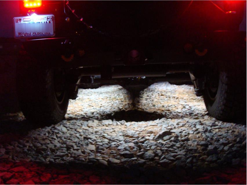
2 2. Choose layout for LiteSPOTs pods. Use integrated magnets to place in preferred locations, but do not permanently mount until all wiring is completed and tested. This will allow you to make adjustments with the pods for best results. An example layout and wiring diagram is included by ORO in the kit (Figure 2). FIGURE 2 - Example layout and wiring diagram provided by ORO in 8 light kit. a. For this example we used three LiteSPOTs pods for each side of the vehicle and one each for the front and rear. The three side locations were evenly spaced for best coverage and the front LiteSPOTs was placed at a slight angle to provide better illumination of the front tire area. (Figure 3) b. The LiteSPOTs were attached to the underside of the vehicle between the frame and the outside edge of the vehicle so that the underside was illuminated, but the LiteSPOTs pods were not visible. (Figure 4)


3 FIGURE 3 LiteSPOTs placement on example vehicle FIGURE 4 LiteSPOTs placement under vehicle

4 3. NOTE: If you are connecting the LiteSPOTs kit to an existing switch such as a spod (Figure 4A) you will not use the switch and flat spade connectors included in the installation kit, and you will not need to complete any additional ground connections to the body as the spod will provide power, ground, and a fuse for the wiring harness. Simply run the 25 foot wiring harness in series to each LiteSPOTs pod, connecting the positive wire for each pod (non-trace) to the harness positive wire (non-trace), and the ground wire for each pod (black-trace) to the harness ground wire (black-trace) to complete the installation. Figure 4A Connection to optional switch (i.e. spod) 4. Hard Wiring to battery - Begin wiring using the wire provided in the kit. Do NOT connect to the battery at this time to prevent injury and/or damage. Be sure to leave enough wire to connect to the positive and negative battery terminals at the completion of the wiring process. (If not wiring through the fuse block it is recommended that you use an inline fuse between the switch and the POSITIVE terminal of the battery). a. Using the provided BLACK 20g wire to attach the flat round terminal (provided in kit) to one end of the BLACK 20g wire (Figure 5).

5 Figure 5 Flat round terminal on 20g BLACK (POSITIVE) wire a. Determine how much wire is needed between the switch location and battery and cut off any extra BLACK 20g wire. Save the remaining BLACK 20g wire for the remaining steps. b. Upon completion of all wiring the other end of the BLACK 20g POSITIVE wire will be connected to the POSITIVE battery terminal of the vehicle (Figure 6) Figure 6 Black 20g POSITIVE wire connected to POSITIVE battery terminal
 Figure 7 Place flat spade terminal on BLACK 20g wire d.")

6 c. Place a flat spade terminal (included in kit) on the other end of the BLACK 20g POSITIVE wire. (Figure 7) Figure 7 Place flat spade terminal on BLACK 20g wire d. Use a high temperature heat gun to melt the solder (silver) in the flat spade terminal and to shrink the tubing at the same time connecting the wires and creating a sealed connection. (Figure 8) Figure 8 Flat spade terminal soldered to BLACK 20g POSITIVE wire


7 e. Connect the flat spade terminal of the BLACK 20g POSITIVE wire to Terminal 1 (12V label) of the switch. (Figure 9). Figure 9 Flat spade terminal connected to Terminal 1 of switch f. Using the same process previously detailed, attach a flat spade terminal to one end of the extra unused BLACK 20g wire. Use the flat spade connector to attach the wire to Terminal 3 of the switch. Terminal 3 is the copper colored terminal on the switch. (Figure 10) Figure 10 BLACK 20g GROUND wire connected to Terminal 3 g. Connect the other end of that wire to the body of the vehicle using a self-tapping screw to GROUND the switch. (Figure 11)
 1.")
8 Figure 11 BLACK 20g wire GROUND connected to vehicle body/frame h. A third section of BLACK 20g wire will be used to connect the switch to the wiring harness that connects all of the LiteSPOTs pods. Connect a flat spade terminal to one end of the wire and attach it to Terminal 2 of the switch. Terminal 2 is the center terminal of the switch. (Figure 12) 1. The other end of this wire will connect wiring harness, which is the 25 foot 2 conductor wire included in the installation kit. 2. One side of the harness has a black trace on it and contains silver wire this is the GROUND side of the harness. The other side of the harness does not have a black trace on it and contains copper wire this is the POSITIVE side of the harness. 3. Connect the BLACK 20g wire from Terminal 2 to the POSITIVE (non-trace) side of the wire harness using one of the Solder Seals included in the installation kit. (Figure 13) i. Attach the GROUND wire of the harness to the body using a self-tapping screw. This can be completed at the end of the wiring harness, or can be spliced into the middle of the wiring harness using a Solder Seal.


9 Figure 12 BLACK 20g wire connected to Terminal 2 Figure 13 BLACK 20g wire connected wiring harness

 to the harness ground wire (blacktrace). Use included zip ties to secure loose wires (Figure 15).")
10 5. Run the wiring harness to each of the pre-positioned LiteSPOTs pods (Figure 14) and use two Solder Seals to connect the pod to the wiring harness. Connect the positive wire for each pod (non-trace) to the harness positive wire (non-trace), and the ground wire for each pod (black-trace) to the harness ground wire (blacktrace). Use included zip ties to secure loose wires (Figure 15). Figure 14 Pre-positioned LiteSPOTs pod Figure 15 Wired LiteSPOTs pod and wires secured using zip tie

11 6. Once all LiteSPOTs pods have been connected to the wiring harness connect the harness to the battery/power source. 7. Turn on switch to test lights and make any needed adjustments to achieve desired results. If you choose to mount the pods permanently, use a drill with a ¼ nut driver and the included self-tapping screws through the pre-drilled hole in the pod to secure the pod to the vehicle (Figure 16). Figure 16 Securing LiteSPOTs pod using self-tapping screw 8. Use zip ties to secure any loose wiring. Conceal wires inside existing wire harness covers under the vehicle for a finished appearance.

12 Completed Install


13 To connect wires using a Solder Seal 1. Separate the harness wires from each other for about 2 inches. 2. Strip about 3/4 of an inch of insulation from the ends of the wires being connected. 3. Slide a Solder Seal onto one of the wires so that the bare end of the wire is exposed (Figure 17) FIGURE 17 Stripped wire and Solder Seal
 FIGURE 18 Connecting wires using Solder Seal 5.")
14 4. Twist the ends of the wires together and then slide the Solder Seal over the connection until the solder (silver) part of the Solder Seal covers the wires to be connected. (Figure 18) FIGURE 18 Connecting wires using Solder Seal 5. Use a high temperature heat gun to melt the solder (silver) in the Solder Seal and to shrink the tubing at the same time connecting the wires and creating a sealed connection. OPTIONAL use electrical tape or additional shrink tubing to create a water-proof seal over all connections. Installation Instructions Written by Extreme Terrain Customer D. Barton 05/21/2015
In This DIY We Will Show You How To Install Recon Backup Lamps (part # To Run On A Separate Switch & In Reverse.
 In This DIY We Will Show You How To Install Recon Backup Lamps (part # 264150 To Run On A Separate Switch & In Reverse. Please Note, There Are Many Ways of Installing These Lights, Including Wiring Methods,
Installation Instructions
 Installation Instructions Jeep JK Unlimited (2007 Present) Mounting Bracket and Air Line System Kit for ARB On-Board Twin Air Compressor (CKMTA12) Made in the USA Kit Contents: 1 Bracket for ARB Compressor
UNPACK AND IDENTIFY THE FOLLOWING PARTS.
 SUT-250-M2 ASSEMBLY REQUIREMENTS *Torque all T-bolt nuts to 35-40 foot pounds. *Check all lights before towing. *Tire pressure not to exceed recommendation on serial tag. *Re-torque wheel nuts after first
LiteDOT Installation Document
 LiteDOT Installation Document This document designed to aid in installation of LiteDOT s on Jeep TJ models, other models are similar. NOTE: Installing LiteDOT s on a Jeep where the 2 necessary mounting
Custom Dynamics Spyder Stingerz Installation Instructions
 Custom Dynamics Spyder Stingerz Installation Instructions We thank you for purchasing the Custom Dynamics Stingerz! Our products utilize the latest technology and high quality components to ensure you
Installation Instructions for the Plug & Play Chrysler/Dodge/Jeep Remote Start Package w/mux T5
 v1.01 12/14/2102 Installation Instructions for the Plug & Play Chrysler/Dodge/Jeep Remote Start Package w/mux T5 Review the remote start installation manual for safety instructions! Overview Your kit consists
Installation Manual for the Pantera Ignition Switch Bypass
 Installation Manual for the Pantera Ignition Switch Bypass This Ignition Switch Bypass solves the Pantera owners problem of replacing the ignition switch that is expensive and difficult to source. The
INSTALLATION GUIDE. AMP RESEARCH TECH SUPPORT (Press 2) Monday - Friday, 6:00 AM - 5:00 PM PST
 Monday - Friday, 6:00 AM - 5:00 PM PST") INSTALLATION GUIDE APPLICATION AMP Part # Jeep Wrangler Unlimited (JK) 2007 2015 75122-01A (-Door Only) INSTALLATION TIME 3-5 Hours Professional installation recommended SKILL LEVEL 1 2 3 = Experienced
INSTALLATION GUIDE APPLICATION AMP Part # Jeep Wrangler Unlimited (JK) 2007 2015 75122-01A (-Door Only) INSTALLATION TIME 3-5 Hours Professional installation recommended SKILL LEVEL 1 2 3 = Experienced
AMP RESEARCH TECH SUPPORT (Press 2) Monday - Friday, 6:00 AM - 5:00 PM PST
 Monday - Friday, 6:00 AM - 5:00 PM PST") APPLICATION AMP Part # Jeep Wrangler Unlimited (JK) 2007 2017 78122-01A (-Door Only) INSTALLATION TIME 3-5 Hours Professional installation recommended SKILL LEVEL 1 2 3 = Experienced TOOLS REQUIRED q 13
APPLICATION AMP Part # Jeep Wrangler Unlimited (JK) 2007 2017 78122-01A (-Door Only) INSTALLATION TIME 3-5 Hours Professional installation recommended SKILL LEVEL 1 2 3 = Experienced TOOLS REQUIRED q 13
I N S T A L L A T I O N G U I D E
 I N S T A L L A T I O N G U I D E APPLICATION AMP Part # Jeep Wrangler Unlimited (JK) 2007 2017 78122-01A (4-Door Only) INSTALLATION TIME 3-5 Hours Professional installation recommended SKILL LEVEL 1 2
Installation Instructions for the Plug & Play Remote Start Package (EVOCHR5)
") T6018 v1.1 02/2013 Installation Instructions for the Plug & Play Remote Start Package (EVOCHR5) For DODGE Nitro 2007-2011 Review the remote start installation manual for safety instructions! Overview Your
T6018 v1.1 02/2013 Installation Instructions for the Plug & Play Remote Start Package (EVOCHR5) For DODGE Nitro 2007-2011 Review the remote start installation manual for safety instructions! Overview Your
Installation Instructions for Lingenfelter GM 2500 Suburban & Yukon XL Auxiliary Fan System (with AC clutch controlled fan output)
") Installation Instructions for Lingenfelter 2007-2013 GM 2500 Suburban & Yukon XL Auxiliary Fan System (with AC clutch controlled fan output) PN L300080607 Revision - 1.1 Lingenfelter Performance Engineering
Installation Instructions for Lingenfelter 2007-2013 GM 2500 Suburban & Yukon XL Auxiliary Fan System (with AC clutch controlled fan output) PN L300080607 Revision - 1.1 Lingenfelter Performance Engineering
Installation Tips for your GM Plug and Play Remote Start Kit EVOGM1 STAND ALONE v1.0 11/27/2013
 Installation Tips for your GM Plug and Play Remote Start Kit EVOGM1 STAND ALONE v1.0 11/27/2013 Thank you for purchasing your remote start from MyPushcart.com - an industry leader in providing remote starts
Installation Instructions for the Plug & Play Remote Start Package (EVOCHR4)
") T6002 v1.1 02/2013 Installation Instructions for the Plug & Play Remote Start Package (EVOCHR4) For CHRYSLER Town & Country 2008-2012 Review the remote start installation manual for safety instructions!
T6002 v1.1 02/2013 Installation Instructions for the Plug & Play Remote Start Package (EVOCHR4) For CHRYSLER Town & Country 2008-2012 Review the remote start installation manual for safety instructions!
Installation Instructions
 Installation Instructions Jeep JK 2-Door (2011 Present) Mounting Bracket and Air Line System Kit for ARB On-Board Twin Air Compressor (CKMTA12) Made in the USA Kit Contents: 1 Flat Bracket 1 Formed Bracket
750 Paso Wiring Upgrade
 750 Paso Wiring Upgrade Supplies required: 2 Bosch 30A/12V Relays # #0 332 209 150 (with mounting tab) 1 30 Amp fuse holder 1 10 Amp fuse holder 12 inches of brown 12 gauge wire 60 inches of red 14 gauge
INSTALLATION GUIDE. AMP RESEARCH TECH SUPPORT (Press 2) Monday - Friday, 6:00 AM - 5:00 PM PST
 Monday - Friday, 6:00 AM - 5:00 PM PST") INSTALLATION GUIDE APPLICATION AMP Part # Jeep Wrangler Unlimited (JK) 2007 up 75121-01A 2-Door INSTALLATION TIME 3-5 Hours Professional installation recommended SKILL LEVEL 1 2 3 = Experienced TOOLS REQUIRED
INSTALLATION GUIDE APPLICATION AMP Part # Jeep Wrangler Unlimited (JK) 2007 up 75121-01A 2-Door INSTALLATION TIME 3-5 Hours Professional installation recommended SKILL LEVEL 1 2 3 = Experienced TOOLS REQUIRED
INSTALLATION INSTRUCTIONS DOCUMENT REVISION : /17/2014
 INSTALLATION INSTRUCTIONS DOCUMENT REVISION : 1.0 10/17/2014 LPF COMPONENT LIST LPF W/ WIRE & GROMMET ( 1 ) M6 X 20MM SCREW ( 2 )* LPF DRIVER BOX ( 1 ) REVERSE CIRCUIT WIRE ( 1 ).25 THICK LICENSE PLATE
JEEP JK4 STEP SLIDER INSTALLATION BD-SS-100-JK4
 JEEP JK4 STEP SLIDER INSTALLATION BD-SS-100-JK4 PARTS LIST QTY DESCRIPTION 1 Drivers Side Slider Assembly 1 Passenger Side Slider Assembly 1 Wiring Harness and Fuse 1 Double Sided Sticky Squares and Alcohol
Turn Signal Kit Installation Instructions for Model A Fords & Other Antique Vehicles
 Turn Signal Kit Installation Instructions for Model A Fords & Other Antique Vehicles Lifetime Technical Support support@logolites.com 770-476-7322 www.logolites.com Manual 100-0005N Thank you for purchasing
Your Legal Fuel Tank Source.
 February 23, 2015 IS# 808 Page 1 of 13 THANK YOU FOR PURCHASING A TRANSFER FLOW 40 GALLON TOOLBOX REFUELING SYSTEM. PLEASE READ THE FOLLOWING PROCEDURES CAREFULLY BEFORE STARTING THE INSTALLATION. CAUTION:
Construction and Wiring Guidelines for Ergon Energy Substation Panels
 Construction and Wiring Guidelines for Ergon Energy Substation Panels Table of Contents Purpose and Scope... 1 Responsibilities... 1 Definitions, Abbreviations and Acronyms... 1 References... 1 Panel Wiring...
Aux. Battery and Isolator
 Aux. Battery and Isolator ISOLATOR MOUNTING ALL YEAR VANAGONS Fig.1 1. Disconnect ground from main battery under passenger seat 2. Remove driver seat 3. Remove driver seat belt buckle from seat pedestal
channel damage the internal components and the weight may break the internal wiring or flexible strip.
 YOU MAY NEED End cap Power adaptor Connector pin Splicing pin Connector Silicone glue Pliers Power converter Converter + surge protector Heat shrink Aluminium channel Heat gun NT cutter IMPORTANT NOTES
Here I Will Explain How To Install Recon Cab Lights In A 3rd Gen Dodge Ram.
 1 P age Here I Will Explain How To Install Recon Cab Lights In A 3rd Gen Dodge Ram. *Now, There Are Many Ways of Installing Them, Including Wiring Methods, Wiring Connectors, And Other Variables - In This
Remote Start Kit for GM Installation RS1/3/4/7 + ADS-DL Tip Sheet
 Remote Start Kit for GM Installation RS1/3/4/7 + ADS-DL Tip Sheet rev 1.4 12/16/2013 Thank you for purchasing your remote start from MyPushcart.com - an industry leader in providing remote starts to do-it-yourself
DODGE RAM 24V 5.9L CUMMINS
 DODGE RAM 24V 5.9L CUMMINS DODGE RAM 24V 5.9L CUMMINS TABLE OF CONTENTS SECTION 1 Preparing the Installation 1 SECTION 2 Boost Gauge Installation 2 SECTION Pyrometer/EGT Gauge Installation 4 SECTION 4
UNPACK AND IDENTIFY THE FOLLOWING PARTS.
 SUT-500-S ASSEMBLY REQUIREMENTS *Torque all T-bolt nuts to 35-40 foot pounds. *Check all lights before towing. *Tire pressure not to exceed recommendation on serial tag. *Re-torque wheel nuts after first
MCL-3000 SERIES AIR PRESSURE PART# MCL-3K-A
 MCL-3000 SERIES AIR PRESSURE PART# MCL-3K-A Thank you for purchasing the Dakota Digital MCL-3K-A gauge for your Harley Davidson Touring bike. This gauge is designed to be a direct, plug in replacement
INSTALLATION INSTRUCTIONS
 2015 - Ford Mustang Qi Wireless Charging Kit (Kit # FDMC-1222) Please read thoroughly before starting installation and check that kit contents are complete. Items Included in the Kit: Qi Wireless Charging
INSTALLATION INSTRUCTIONS
 OEM Recessed Lip Camera with Harness and Slimline Mirror (Kit part number 9002-8724) Please read thoroughly before starting installation and check that kit contents are complete. Items Included in the
Splicing Procedures 4. 2 Insert the new wire between the parted strands. If more than one wire is being spliced, wrap them in opposite directions. Use
 Splicing Procedures 1 Splicing Procedures Refer to applicable wiring diagrams for circuit information. This procedure contains multiple splicing techniques. Review splicing procedures prior to performing
PRODUCT: TJ/LJ Low Profile Led Light Kit READ INSTRUCTIONS IN FULL BEFORE INSTALLATION. QUESTIONS? CALL M-F 7:00 AM 5:00 PM PST
 PRODUCT: TJ/LJ Low Profile Led Light Kit READ INSTRUCTIONS IN FULL BEFORE INSTALLATION. QUESTIONS? CALL 916-631-8071 M-F 7:00 AM 5:00 PM PST REV: E 07-01-2015 II-2208 The MetalCloak experience includes
JEEP JK4 STEP SLIDER INSTALLATION BD-SS-100-JK4
 JEEP JK4 STEP SLIDER INSTALLATION BD-SS-100-JK4 PARTS LIST QTY DESCRIPTION 1 Drivers Side Slider Assembly 1 Passenger Side Slider Assembly 1 Wiring Harness and Fuse 1 Double Sided Sticky Squares and Alcohol
MY F150 SuperCab 1. Tools Required. Page 1 of 12 9L3J-19A014-BA Copyright Ford 2013 FoMoCo
 2009-2014MY F150 SuperCab 1 Tools Required A B C D E F G 3X 6X 3X H I J 2X 3X 3X K L M N 3X Page 1 of 12 9L3J-19A014-BA Copyright Ford 2013 FoMoCo 2009-2014MY F150 SuperCab 2 Subwoofer Power Wire Routing
Installation of Auto Meter Cobalt Boost/Vacuum Gauge:
 Installation of Auto Meter Cobalt Boost/Vacuum Gauge: Fitment: All 79-14 models. This installation was completed on a 2004 Mustang GT, and should be identical for all 1999-2004 model Mustangs. Time needed:
INSTALLATION MANUAL STEP SLIDER BD-SS-200-JK4. Made in the USA. Front Bracket Middle Bracket Rear Bracket. Tools Required
 Made in the USA INSTALLATION MANUAL STEP SLIDER BD-SS-200-JK4 Description Quantity Electric Step Slider (Pair) 2 Front Bracket Middle Bracket Rear Bracket Bump stop plate with VHB backing 2 Wiring harness
I N S T A L L A T I O N G U I D E. AMP RESEARCH TECH SUPPORT (Press 2) Monday - Friday, 6:00 AM - 5:00 PM PST
 Monday - Friday, 6:00 AM - 5:00 PM PST") I N S T A L L A T I O N G U I D E APPLICATION AMP Part # Jeep Wrangler Unlimited (JK) 2007 2014 75121-01A 2-Door INSTALLATION TIME 3-5 Hours Professional installation recommended SKILL LEVEL 1 2 3 4 4=
I N S T A L L A T I O N G U I D E APPLICATION AMP Part # Jeep Wrangler Unlimited (JK) 2007 2014 75121-01A 2-Door INSTALLATION TIME 3-5 Hours Professional installation recommended SKILL LEVEL 1 2 3 4 4=
TIP SHEET. Installation Tips for your RS OL-MDB-CH6 (1) (for Jeep vehicles) T1227 v1.0 3/19/14
 (for Jeep vehicles) T1227 v1.0 3/19/14") TIP SHEET Installation Tips for your RS-360 + OL-MDB-CH6 (1) (for Jeep vehicles) T1227 v1.0 3/19/14 Thank you for purchasing your remote start from MyPushcart.com - an industry leader in providing remote
TIP SHEET Installation Tips for your RS-360 + OL-MDB-CH6 (1) (for Jeep vehicles) T1227 v1.0 3/19/14 Thank you for purchasing your remote start from MyPushcart.com - an industry leader in providing remote
I N S T A L L A T I O N G U I D E. AMP RESEARCH TECH SUPPORT (Press 2) Monday - Friday, 6:00 AM - 5:00 PM PST
 Monday - Friday, 6:00 AM - 5:00 PM PST") I N S T A L L A T I O N G U I D E APPLICATION AMP Part # Jeep Wrangler Unlimited (JK) 2007 2017 78121-01A 2-Door INSTALLATION TIME 3-5 Hours Professional installation recommended SKILL LEVEL 1 2 3 4 4=
I N S T A L L A T I O N G U I D E APPLICATION AMP Part # Jeep Wrangler Unlimited (JK) 2007 2017 78121-01A 2-Door INSTALLATION TIME 3-5 Hours Professional installation recommended SKILL LEVEL 1 2 3 4 4=
Adjustable Light Kits E-Z-Go TXT All Models Installation Instructions
 Adjustable Light Kits E-Z-Go TXT All Models 1996-2013 Installation Instructions Caution: Please read through the instructions carefully. Before starting this project, remove the system s positive and negative
LED Driving Light Set For 2014 & Newer Can-Am Spyder RT # CA006-RT
 LED Driving Light Set For 2014 & Newer Can-Am Spyder RT # CA006-RT 1. Lay-out and familiarize yourself with the components supplied with this set. 2. Remove the left mirror by pulling firmly outward on
SPACESAVER EC-300 A ELECTRICS
 INSTALLATION INSTRUCTIONS SPACESAVER EC-300 A ELECTRICS SECTION I TOP MOUNTED ELECTRICS SECTION II FACE PANEL MOUNTED ELECTRICS SECTION III ZFS INSTALLATION INSTRUCTIONS This symbol indicates a connection
TIP SHEET EVO-CHRT6(d) STAND-ALONE ADD-ON REMOTE STARTER
 STAND-ALONE ADD-ON REMOTE STARTER") TIP SHEET EVO-CHRT6(d) STAND-ALONE ADD-ON REMOTE STARTER Txxxx -The EVO-ALL data and bypass interface module eliminates the need for many wiring connections associated with traditional remote starter installations
TIP SHEET EVO-CHRT6(d) STAND-ALONE ADD-ON REMOTE STARTER Txxxx -The EVO-ALL data and bypass interface module eliminates the need for many wiring connections associated with traditional remote starter installations
HP10134 & HP10135 KITS BASIC SIMULTANEOUS AIR SPRING ACTIVATION KIT
 HP10134 & HP10135 KITS BASIC SIMULTANEOUS AIR SPRING ACTIVATION KIT Thank you and congratulations on the purchase of a Pacbrake simultaneous air spring activation kit. This kit was designed to add in-cab
AUXILIARY BATTERY BOX INSTALLATION INSTRUCTIONS
 AUXILIARY BATTERY BOX INSTALLATION INSTRUCTIONS The original TOMMY GATE hydraulic lift Assembling the Auxiliary Battery Box 1. Remove the cover from the auxiliary battery box by removing the two nuts and
English. Fitting Instructions: Trophy and Trophy SE A of 12. Parts Supplied:
 English Fitting Instructions: Trophy and Trophy SE A9808015 Thank you for choosing this Triumph genuine accessory kit. This accessory kit is the product of Triumph's use of proven engineering, exhaustive
PN CHEVY TRI-FIVE. Kit Contents: Four panel Sequential LED Taillight kit installation guide
 Four panel Sequential LED Taillight kit installation guide Kit Contents: 2 tail light LED panels 2 tail light turn signal LED panels 1 rubber boot/sleeve kit 1 power wire with t-tap 1 driver side LED harness,
SUBJECT: I/M Readiness Check Continues To Indicate OBD System Is Not Ready For I/M Testing
 NUMBER: 25-001-07 GROUP: Emissions DATE: February 09, 2007 This bulletin is supplied as technical information only and is not an authorization for repair. No part of this publication may be reproduced,
TIP SHEET Installation instructions for EVO-NIST1 + LC1
 TIP SHEET Installation instructions for EVO-NIST1 + LC1 T3108 NISSAN INFINITY CUBE 2009-2014 M37 2010-2013 JUKE 2011-2016 M56 2011-2013 QUEST 2011-2016 Q70 2014-2015 SENTRA 2013-2016 Q70L 2015 VERSA SEDAN
MY F150 CrewCab 1. Tools Required E F G. Page 1 of 10 9L3J-19A014-AA Copyright Ford 2013 FoMoCo
 2009-2014MY F150 CrewCab 1 Tools Required A B C D 3X E F G H 2X I 6X 3X Page 1 of 10 9L3J-19A014-AA Copyright Ford 2013 FoMoCo 2009-2014MY F150 CrewCab 2 Subwoofer Power Wire Routing All Vehicles WARNING:
Installation Tips for your Add-on Remote Start (for GM vehicles with INTSL Install 2) v3.2 Updated 11/12/2012
 v3.2 Updated 11/12/2012") Installation Tips for your Add-on Remote Start (for GM vehicles with INTSL Install 2) v3.2 Updated 11/12/2012 Thank you for purchasing your remote start from MyPushcart.com - an industry leader in providing
Installation Tips for your Add-on Remote Start (for GM vehicles with INTSL Install 2) v3.2 Updated 11/12/2012 Thank you for purchasing your remote start from MyPushcart.com - an industry leader in providing
Installing Ignition Coil relay
 Installing Ignition Coil relay Above is a schematic diagram of the coil relay modification. All it really does is, it uses the existing 12 Volt positive that normally powers the coils, to power a relay,
Jeep Wrangler Unlimited (JK) 2007 up A 2-Door. 3-5 Hours INSTALLATION GUIDE INSTALLATION TIME SKILL LEVEL. 4= Experienced TOOLS REQUIRED
 2007 up A 2-Door. 3-5 Hours INSTALLATION GUIDE INSTALLATION TIME SKILL LEVEL. 4= Experienced TOOLS REQUIRED") INSTALLATION GUIDE APPLICATION AMP Part # Jeep Wrangler Unlimited (JK) 2007 up 751-01A 2-Door INSTALLATION TIME 3-5 Hours Professional installation recommended SKILL LEVEL 1 2 3 = Experienced TOOLS REQUIRED
INSTALLATION GUIDE APPLICATION AMP Part # Jeep Wrangler Unlimited (JK) 2007 up 751-01A 2-Door INSTALLATION TIME 3-5 Hours Professional installation recommended SKILL LEVEL 1 2 3 = Experienced TOOLS REQUIRED
EMS Installation Instructions
 EMS Installation Instructions The EMS1 and EMS2 are functionally identical and, as such, their installation is identical. Both EMS versions use the same connector as follows: EMS1 Walk-through video on
SUT-250-S (These instructions are used for SUT-250-SCLC also)
") SUT-250-S (These instructions are used for SUT-250-SCLC also) Torque wrench, carpenters square, wire cutters, Phillips screwdriver, 7/16, 9/16, and 3/4 combination wrenches, ratchet, 9/16, 3/4, 13/16,
SUT-250-S (These instructions are used for SUT-250-SCLC also) Torque wrench, carpenters square, wire cutters, Phillips screwdriver, 7/16, 9/16, and 3/4 combination wrenches, ratchet, 9/16, 3/4, 13/16,
MAGNETO REPLACEMENT. Pre-Unit Twin Cylinder Motorcycles. ELECTRONIC IGNITION SYSTEM For 4 Stroke. With 12 VOLT Electrics, POS/ NEG Ground
 Sure ー Fire MAGNETO REPLACEMENT ELECTRONIC IGNITION SYSTEM For 4 Stroke Pre-Unit Twin Cylinder Motorcycles With 12 VOLT Electrics, POS/ NEG Ground SYSTEM TYPE: PAMT1 2 Sure-Fire System Contents: MAGNETO
UNIVERSAL GAUGE WIRE HARNESS
 2650-1797-00 UNIVERSAL GAUGE WIRE HARNESS For Installing Auto Meter Electric Speedometer, Tachometer, And Short Sweep Electric Oil Pressure, Water Temperature, Fuel Level, and Volt Meter Gauges. This harness
INSTALLATION INSTRUCTIONS
 Qi Wireless Charging Installer Kit (Kit # FDMC-1210) INSTALLATION INSTRUCTIONS Please read thoroughly before starting installation and check that kit contents are complete. Items Included in the Kit: Qi
Zeon Control Pack Relocation Kit 78 Cable Length
 ORIGINAL INSTRUCTIONS SYMBOL INDEX SYMBOL EXPLANATION SYMBOL EXPLANATION Read All Product Literature Always Wear Leather Gloves Always Wear Hearing and Eye Protection Do Not Move People Zeon Control Pack
INSTALLATION INSTRUCTIONS
 Equipped with AEM Dryflow Filter No Oil Required! INSTALLATION INSTRUCTIONS PART NUMBER: 24-6105 2002-2006 ACURA RSX - Excludes Type S L4-2.0L C.A.R.B. E.O. # D-670 * NOTE: Legal in California only for
Installation Tips for your Crimestopper/ProStart Remote Start system (for GM vehicles) v1.01 updated 2/27/2012
 v1.01 updated 2/27/2012") Installation Tips for your Crimestopper/ProStart Remote Start system (for GM vehicles) v1.01 updated 2/27/2012 Thank you for purchasing your remote start from MyPushcart.com - an industry leader in providing
Installation Tips for your Crimestopper/ProStart Remote Start system (for GM vehicles) v1.01 updated 2/27/2012 Thank you for purchasing your remote start from MyPushcart.com - an industry leader in providing
WirelessAIR Advanced Integrated Remote
 Advanced Integrated Remote Gen 3 Kit 72000 Automatic Leveling Digital On-Board Compressor System MN-772 (021112) ECR 7233 INSTALLATION GUIDE For maximum effectiveness and safety, please read these instructions
Cantilever Series Mounting Instructions Fullsize Sprinter Van (US) All except WB (AA) present
 All except WB (AA) present") Fullsize Sprinter Van (US) All except 3500 144 WB (AA)- 2007-present Preparing the Gate 1. Remove the platform, mounting kit, license plate assembly, and bridge assemblies, which are banded to the main
Fullsize Sprinter Van (US) All except 3500 144 WB (AA)- 2007-present Preparing the Gate 1. Remove the platform, mounting kit, license plate assembly, and bridge assemblies, which are banded to the main
3-5 Hours Professional installation recommended
 I N S T A L L A T I O N G U I D E APPLICATION LENGTH MODEL YR PART # Chevrolet Colorado / GMC Canyon - Crew Cab 72 2015-2016 76153-01A Chevrolet Colorado / GMC Canyon - Extended Cab 65 2015-2016 76153-01A
Installation instructions:
 www.beetelo.com Kawasaki Vulcan 1700 (VN1700) Integrated turn signal, license plate relocator mount Vaquero, Nomad, Classic, Voyager, Classic Tourer (LT) Kawasaki Vulcan 900 VN900 Classic, Classic LT,
Marine Exhaust Temperature Alarm. COMPONENTS
 Marine Exhaust Temperature Alarm. Model: SM0012 INTRODUCTION COMPONENTS Marine water cooled exhaust systems are designed to withstand temperatures of up to about 120 C. However the exhaust gases from the
Installation Instructions for Stand Alone Remote Starter (EVO-ALL-THAR-GM2) Firmware: 4.18, OPTION 15. T2362 Rev#1.2 last updated 10/15/13
 Firmware: 4.18, OPTION 15. T2362 Rev#1.2 last updated 10/15/13") Installation Instructions for Stand Alone Remote Starter (EVO-ALL-THAR-GM2) Firmware: 4.18, OPTION 15. T2362 Rev#1.2 last updated 10/15/13 -The new EVO-ALL interface module eliminates the need for a separate
Installation Instructions for Stand Alone Remote Starter (EVO-ALL-THAR-GM2) Firmware: 4.18, OPTION 15. T2362 Rev#1.2 last updated 10/15/13 -The new EVO-ALL interface module eliminates the need for a separate
INSTALLATION INSTRUCTIONS THERMOCOUPLE EXPANSION MODULE
 INSTALLATION INSTRUCTIONS THERMOCOUPLE EXPANSION MODULE 2650-1846-77 Rev. B Details: Temperature Rating: -40 C to 85 C/-40 F to 185 F Vibration Specification: 20 g continuous, 50 g shock Inputs: o 4 EGT
LGT-312L E-Z-Go TXT Light Bar Bumper Kit Installation Instructions
 LGT-312L E-Z-Go TXT 2014+ Light Bar Bumper Kit Installation Instructions Caution: Please read through the instructions carefully. Before starting this project, remove the system s positive and negative
JEEP JK4 STEP SLIDER INSTALLATION BD-SS-200-JK4 / BD-SS-201-JK4
 JEEP JK4 STEP SLIDER INSTALLATION BD-SS-200-JK4 / BD-SS-201-JK4 Installaton Instructon RSEI 106 P A R TS L IST QTY DESCRIPTION 1 Drivers Side Slider Assembly 1 Passenger Side Slider Assembly 1 Wiring Harness
I N S T A L L A T I O N G U I D E. Chevrolet Silverado / GMC Sierra - Ext Cab * A (Diesel Only)
") I N S T A L L A T I O N G U I D E APPLICATION AMP Part # Chevrolet Silverado / GMC Sierra - Crew Cab 2011-201 751-01A (Diesel Only) Chevrolet Silverado / GMC Sierra - Ext Cab 2011-201* 751-01A (Diesel
I N S T A L L A T I O N G U I D E APPLICATION AMP Part # Chevrolet Silverado / GMC Sierra - Crew Cab 2011-201 751-01A (Diesel Only) Chevrolet Silverado / GMC Sierra - Ext Cab 2011-201* 751-01A (Diesel
Gauge Wiring Instructions
 Thank you for purchasing the Track Dog Racing Gauges. These instructions are for wiring the Westach brand gauges with the TDR gauge panel for all model years of the Miata. Refer to the installation instructions
Dodge Ram 09-Current CS-DTR SERIES BACKUP CAMERA INSTALLATION
 Dodge Ram 09-Current CS-DTR SERIES BACKUP CAMERA INSTALLATION Thank you for your purchase! These instructions cannot possibly cover every option group for every model year of RAM trucks so you may find
Fitting Instructions
 Reverse Park Assist Suitable for: Isuzu MU-X Kit Part No: / 5466XX D-Max Tow-Pro Wiring Kit Fitting Instructions Suitable for: Isuzu MU-X / D-Max Accessory Kit Estimated Fitting Time: 0 Minutes FI967 Page
How to Install and Remove a standard Teletrac Transceiver.
 How to Install and Remove a standard Teletrac Transceiver. April 27 2010 Draft: 001.fc.4_10.doc Introduction. This document is comprised of two independent sections. The first section addressed all the
OLDSMOBILE CUTLASS
 1971-72 OLDSMOBILE CUTLASS Four Panel Sequential LED Tail Light Kit Installation Guide Kit Contents: 4 LED panels 1 Connector/Wire Kit 1 Grommet/Boot Kit 1 Power wire 2 Pigtail Harness Kits 1 Crimp terminal
Install Instruc & Recommended Procedures
 Install allation Instruc uctions & Recommended Procedures Unlike other radar detectors and aftermarket accessories, the K40 Calibre will not interfere with the vehicle's complex electronic systems. The
Fitting Instructions: Street Triple from VIN and Street Triple R from VIN A
 English Fitting Instructions: Street Triple from VIN 560477 and Street Triple R from VIN 560477 A9808113 Thank you for choosing this Triumph genuine accessory kit. This accessory kit is the product of
Installation Tips for your Crimestopper/ProStart Remote Start system (add-on for GM vehicles) v1.02 updated 1/16/2013
 v1.02 updated 1/16/2013") Installation Tips for your Crimestopper/ProStart Remote Start system (add-on for GM vehicles) v1.02 updated 1/16/2013 Thank you for purchasing your remote start from MyPushcart.com - an industry leader
Installation Tips for your Crimestopper/ProStart Remote Start system (add-on for GM vehicles) v1.02 updated 1/16/2013 Thank you for purchasing your remote start from MyPushcart.com - an industry leader
U L T I M A T E R A D A R / L A S E R D E F E N S E S Y S T E M
 S m a r t e r Q u i e t e r M o r e A c c u r a t e U L T I M A T E R A D A R / L A S E R D E F E N S E S Y S T E M Installation Manual PASSPORT 9500ci Comes Complete Front Radar Receiver Miniature weatherproof
Jeep JK Wrangler XHD Rear Tire Carrier
 Contents: 1. Frame (1) 2. Pivot Mount (1) 3. Latch Mount (1) 4. Lug Nuts (3) 5. Catch Pin (1) 6. M12 Washer (18) 7. M12 x 30 Hex Bolt (14) 8. Brake Light Mount (1) 9. Snap Ring (1) 10. Rub Strip (1) 11.
Installation Guide The RSi brief overview:
 Electronic Rust Protection Installation Guide The RSi brief overview: The RustStop RSi Industrial uses a 6 channel output system to drive up to 18 anodes (Rust Magnets ) Each channel has its own output
INSTRUCTIONS. w w w. h d o n l i n e s h o p. d e SPRINGER AUXILIARY LAMP KIT 1WARNING -J03497 REV General.
 INSTRUCTIONS -J097 REV. 0-0-00 Kit Number 6986-0A General Auxiliary/fog lamps are not included in this kit. The lamps must be purchased separately. HDI (International) motorcycles should only use approved
SYSTEM OPERATION IMPORTANT CAUTIONS
 SYSTEM OPERATION The system is turned on by placing the gear shift lever in the reverse position. The green light on the cab Control Box will illuminate to indicate the system is operating. When an object
Deegan 38 HD Rock Sliders w/ LED Rock Lights (07-18 Wrangler JKU)
") Installation Time: 2-3 Hours Deegan 38 HD Rock Sliders w/ LED Rock Lights (07-18 Wrangler JKU) Note: This kit comes with everything you need to wire the lights with a switch in the cab. However, I recommend
Installation Time: 2-3 Hours Deegan 38 HD Rock Sliders w/ LED Rock Lights (07-18 Wrangler JKU) Note: This kit comes with everything you need to wire the lights with a switch in the cab. However, I recommend
HDMD-200/300 Universal display
 Universal display I n s ta l l at i o n G u i d e Micro Display Kit 9 Mendenhall Drive North Las Vegas, NV 8908 www.dynojet.com -800-99-4993 www.dynojet.com Display unit Attachment Pegs Cable Harness Hex
PROBLEMS OR QUESTIONS? Or via
 INCLUDED ITEMS: (1) left and (1) right Signal Mirror (Flat Glass) and housing, (1) left and (1) right wire harness, (2) 1.5 long 5 / 16-24 Allen head bolts, (1) 8 shrink tube, (1) ring connector, (6) nylon
650 Series Cargo Van Lift Mounting Instructions Ford Transit (Standard Roof) 2015-Present
 2015-Present") TOMMY GATE OWNER'S / OPERATOR'S MANUAL 650 Series 650 LB Capacity 650 Series Cargo Van Lift Mounting Instructions Ford Transit (Standard Roof) 2015-Present Installing the Base Plate 1. Examine the interior
TOMMY GATE OWNER'S / OPERATOR'S MANUAL 650 Series 650 LB Capacity 650 Series Cargo Van Lift Mounting Instructions Ford Transit (Standard Roof) 2015-Present Installing the Base Plate 1. Examine the interior
Build Manual. for Studying Electrical Conductivity using a 3D Printed 4-Point Probe Station
 Build Manual for Studying Electrical Conductivity using a 3D Printed 4-Point Probe Station 1 Materials 1. 3D printed parts Head support Trigger Front Probe head panel Right panel Middle panel Left panel
Rocket Locker. Installation Guide. October 2012
 Rocket Locker Installation Guide October 2012 Notices The contents of this document and the associated software are the property of Utility, Inc. Any reproduction in whole or in part is strictly prohibited.
3-5 Hours Professional installation recommended
 I N S T A L L A T I O N G U I D E APPLICATION AMP Part # Chevrolet Silverado 2500/3500 / GMC Sierra 2500/3500 - Ext. Cab * 2007-201 75126-01A Chevrolet Silverado 2500/3500 / GMC Sierra 2500/3500 - Crew
INSTALLATION INSTRUCTIONS FUEL SURGE TANK KIT
 INSTALLATION INSTRUCTIONS FUEL SURGE TANK KIT BMW E46 3-Series, Excl Convertible Document: 19-0056 Support: info@radiumauto.com Relieve fuel pressure in vehicle before beginingthe installation. Disconnect
INSTALLATION INSTRUCTIONS
 Jeep Wrangler Rear Vision Camera, 2007 Current (Kit # 9002-8838) Items Included in the Kit Camera Chassis Harness Zip lock bag with 15 Wire Ties & 3 Push Nuts These Instructions Required Tools & Supplies
V6 Mustang BBK Long Tube Headers and Shorty X-Pipe:
 2011-2012 V6 Mustang BBK Long Tube Headers and Shorty X-Pipe: Time Required: Approximately 9 hours w/ 3 installers (highly recommended having help during install); process will be much faster with a lift
Backside License Plate Mount for Jeep JK Wrangler
 REQUIRED TOOLS 10mm SOCKET 13mm SOCKET 4mm HEX KEY WIRE CRIMPS WIRE STRIPPERS ELECTICAL TAPE SCREW DRIVER KIT CONTAINS BACKSIDE MOUNT LICENSE PLATE BRACKET WITH LEDS PLASTIC PASS-THROUGH GROMMET STAINLESS
PRODUCT INSTALLATION GUIDE
 PRODUCT INSTALLATION GUIDE PRODUCT CODE: PRODUCT DESCRIPTION: 4WDXHDSFK 4WD EXTREME HEAVY DUTY 6 COUPLER SYSTEM SELF FIT KIT KIT CONTENTS: QTY PRODUCT QTY PRODUCT QTY PRODUCT 1 Couplertec Module 3 Black
Club Car 1510 to Curtis 1268 Conversion
 Club Car 1510 to Curtis 1268 Conversion Installation Instructions 62-12685501CKI Rev. 05 7/18/14 Page 1 of 7 1510 to Curtis 1268 Conversion Installation Instructions Before you start turn Tow/Run switch
This method is for vehicles having a manual transmission. For vehicles with automatic transmissions, use this diagram.
 Engine - Exhaust - Brake The engine's Exhaust Back Pressure Valve (EBPV) is a butterfly type valve located on the outlet of the turbocharger, between the turbine and the downpipe. It is controlled by the
Trail Rocker Installation
 Trail Rocker Installation Instructions 4, 6, or 8 - Switch Customizable Trail Rocker Switch Panel w/ Flanged Mount For Installing Painless Part Number: 57103, 57106, & 57109 Manual #90636 Painless Performance