microcomp SERIES Miniature Lightweight High Density Connectors Space Grade - ESA QPL
|
|
|
- Angelica Dorsey
- 5 years ago
- Views:
Transcription

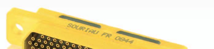


1 microcomp SERIES Miniature Lightweight High Density Connectors Space Grade - ESA QPL
2


3 Space Grade microcomp Contents Overview... 4 Features and benefits... 6 Comparison with micro-d... 7 Comparison with high density D-Sub... 8 Technical Features Weight - Mating Forces...12 Qualified following ESA procedure...13 Quality levels and controls...14 Lot acceptance tests...15 Contact layouts...16 Contact types...17 Ordering information Crimp removable contacts...20 Mating dimensions and contact position...21 Wiring instructions...22 Dimensions Mounting operations and hardware PCB drilling...32 Mounting hardware Savers EMI Backshells Dust Caps...49

 an innovative high density connector range:")


 SMU (Satellite management unit) Star tracker For")

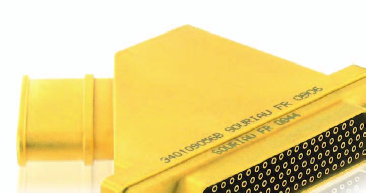
4 Overview Description To respond to miniaturization and weight saving trends in space applications SOURIAU has developed, at the request of the European Space Agency (ESA) an innovative high density connector range: microcomp is the alternative to High Density D-Sub and micro-d. ESA QPL Shell in composite: very light and non magnetic Save up to 65% in weight compared to HD D-Sub High density: save more than 40% in size compared to HD D-Sub Crimp removable contacts : repairable harnesses High vibration and shock withstanding Non-outgassing Low mating/unmating force Applications For communication, military, observation and science satellites equipment: Power Distribution Unit Solar panel Satellite camera Avionics Battery management PIU/ PLIU (Payload interface units) SMU (Satellite management unit) Star tracker For micro satellites and probes For Launcher : Test benches Engine control Unit and any electronic device with space and weight constraints. For MIL/Aero applications consult our dedicated Aeronautical and Defense microcomp catalog. 4
5 SOURIAU: a specialist in space connection technology Souriau is ESA (European Space Agency) qualified since Today Souriau is ESA QPL for: - microcomp - D-Sub (Standard and High Density) - MIL-DTL Strength of ESA system: - These qualifications are reviewed every 2 years, according to ESCC basic specification Any change in manufacturing process is submited to ESA approval. Manufacturing processes are fully recorded in a PID (Process Identification Document). Souriau is GSFC (NASA) qualified since Today Souriau is GSFC QPL for D-Sub (Standard and High density) microcomp is ESA QPL Qualified to ESA (European Space Agency) generic specifications 3401 Chart IV and microcomp specifications: These specifications are available on ESA SCC web site: Generic Specification for connectors electrical Circular and Rectangular Connectors, electrical, rectangular, microminiature, gauge 26 PCB Pin Contacts, based on type microcomp Connectors, electrical, rectangular, microminiature, removable gauge 26 crimp contacts, based on type microcomp Contacts, electrical, gauge 26, for 3401/082 connectors Accessories for rectangular connectors, microminiature 3401/081 and 3401/ pdf pdf pdf pdf pdf 5


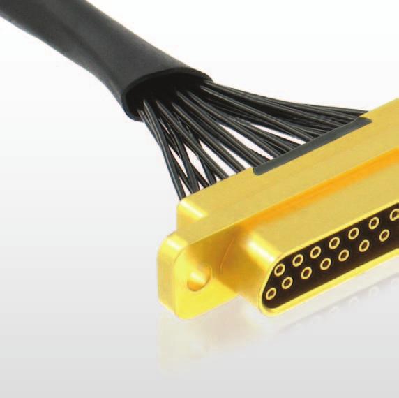
6 Features and benefits Composite shell benefits microcomp shells are available in glass fiber reinforced themoplastic material for maximum mechanical resistance. Composite shells are up to 36% lighter than their equivalent in aluminum and are non-magnetic by nature. The advanced Gold over composite plating process used on microcomp provides optimized shielding and shell-toshell continuity and is the result of years of R&D. microcomp pins are protected microcomp male connectors are "damage proof". On HD D-Sub and D-Sub male contacts are the fragile parts of the connector because they can easily be bent. On microcomp male contacts are fully shrouded by the insulator: they are protected and can t be bent. 26 ways D-Sub with male contacts 25 ways microcomp with male contacts Male D-Sub contacts not protected Male microcomp contacts protected by the insulator microcomp for high speed network Thanks to short contacts and good EMI performances microcomp can be used for Cat 5e Gigabit Ethernet 1000 base T links. Contact us for more information about wiring for Ethernet: microcomp@souriau.com 6
7 Comparison with micro-d microcomp benefits: Save money: global cost of ownership is less expensive for microcomp than for micro-d. With micro-d any change in design or quality issue leads to complete harness replacement as micro-d are pre-wired and non repairable. microcomp solution is more flexible thanks to the removable crimp contacts. Save time in development: microcomp has removable crimp contacts so you can easily and quickly change your harness configuration. Save weight: the high technology composite shells (strengthened fiber glass material for maximum mechanical resistance) makes microcomp very light and robust. Same panel cut-out: microcomp connectors have the same external dimensions as MIL-DTL (except for size H and J). Easier to use: mating and unmating force is lower for microcomp than for micro-d. Weight comparison: microcomp is lighter Comparison between the max weight (connector + contacts) given in microcomp standard (ESCC 3401/081, 082, 083) and in micro-d standard (ESCC 3401/029). microcomp micro-d microcomp micro-d microcomp micro-d Number of contacts Plug without cable 1,42 gr 2,20 gr 3,60 gr 4,30 gr 6,01 gr 7,20 gr Receptacle with 90 spills 1,68 gr 7,40 gr 4,60 gr 10,20 gr 8,39 gr 16,50 gr Average weight per contact 0,44 gr 1,07 gr 0,33 gr 0,58 gr 0,28 gr 0,46 gr Weight saved per contact with microcomp (%) 58% 43% 39% Mating force comparison: microcomp is easier to mate and unmate even with more than 100 contacts. Comparison between the max mating and unmating force given in microcomp standard (ESCC 3401/081, 082, 083) and in micro-d standard (ESCC 3401/029 for sizes 9, 25, 51. MIL-DTL for size 100 because there is no micro-d space standard for size 100). microcomp micro-d microcomp micro-d microcomp micro-d microcomp micro-d Number of contacts Max mating/unmating force (N) 12N 20N 43N 55N 87N 113N 179N 283N Difference in N 8N 13N 26N 104N Saving in % 41% 23% 23% 37% 7
8 Comparison with high density D-Sub microcomp benefits: Save room and weight on your equipment: for signal applications, replace your HD D-Sub with microcomp and reduce your equipment dimensions and weight. HD D-Sub microcomp 26 cts 25 cts 44 cts 51 cts 78 cts 104 cts Size comparison: microcomp is smaller Comparison between the max dimensions given in microcomp standard (ESCC 3401/081) and in HD D-Sub space standard (ESA ESCC /002/005, NASA GSFC S-311-P-4D). microcomp HD-DSub microcomp HD-DSub microcomp HD-DSub Number of contacts Front dimension (max) 2,9 cm² 5,1 cm² 4,3 cm² 6,9 cm² 7,8 cm² 12,1 cm² Size saving / HD Dsub 42% 37% 35% Surface per contact 11,8 mm² 19,7 mm² 8,5 mm² 15,7 mm² 7,5 mm² 11,6 mm² Size saving per contact / HD Dsub 40% 46% 35% *ESCC only Weight comparison: microcomp is lighter Comparison between the max weight given in microcomp standard (ESCC 3401/081, 082, 083) and in HD D-Sub standard ESA ESCC /002/005 (no weight data in GSFC S-311-P-4D) microcomp HD-DSub microcomp HD-DSub microcomp HD-DSub Number of contacts Plug without cable 3,60 gr 9,48 gr 6,01 gr 14,52 gr 10,99 gr 31,32 gr Receptacle with 90 spills 4,60 gr 14,00 gr 8,39 gr 22,14 gr 17,54 gr 51,04 gr Average weight per contact 0,33 gr 0,90 gr 0,28 gr 0,83 gr 0,27 gr 0,79 gr Weight saved per contact with microcomp (%) 64% 66% 65% Mating force comparison: microcomp is easier to mate and unmate even with more than 100 contacts. Comparison between the max mating/unmating force given in microcomp standart (ESCC 3401/081) and in HD D-sub space standard GSFC S-311-P-4D. (Note: ESCC max mating force are higher than GSFC). microcomp HD-Dsub microcomp HD-Dsub microcomp HD-Dsub Number of contacts Max mating/unmating force (N) 43N 76N 87N 125N 179N 289N Difference in N 33N 38N 110N Saving in % 44% 30% 38% 8

9 Technical characteristics Electrical Contact size: #26 Contact pitch: 2 mm Current rating: 2.5 Amps Dielectric Withstanding Voltage sea level: 600 VRMS feet: 200 VRMS Working voltage sea level: 150 VRMS 70,000 feet: 100 VRMS Insulation resistance: 5,000 MΩ Low level contact resistance: 6 mω Rated current contact resistance: <5 mω Admissible wire gauge: AWG 24 to 28 Shielding effectiveness: > 60dB attenuation from 1 to 500 MHz Shell to shell continuity: Composite version: < 2mΩ Aluminum version: < 2mΩ Mechanical Endurance / Durability: 500 mating/unmating operations Contact retention in insert: 15 N Vibration: Random: 44g (ESA requirements: 20g) Sine: 20g Shock: 50g Climatic Operating temperature range: -55 C to +175 C (ESA requirements: -55 C / +125 C) Storage temperature range -65 C to +125 C Soldering temperature: +260 C Salt spray (corrosion): Composite shell = 2000 hrs Aluminum shell = 48 hrs Environmental RoHS: compliant Material and finishes: Shell: composite (glass fiber reinforced material for maximum mechanical resistance) or Aluminum Shell plating: 1.27 µm (.50 µinch) Au Contact: copper alloy Contact plating: 1.27 µm (.50 µinch) Au according to Type 2, Grade C of MIL-DTL Underplate of 1.00µm ( in) min of Copper or High phosphorus chemical Nickel Insulator: thermoplastic Mounting accessories (Jackscrews, jackposts, clip): stainless steel, passivated per QQ-P-35 Grommet and seal: silicone rubber Drilled bar: thermoplastic Space Outgassing: 1% Total Mass Loss max 1% Recovered Mass Loss max 0.1% Collected Volatile Condensible Materials Residual Magnetism: < 200 gamma For more information or questions, please contact microcomp@souriau.com 9
10 Technical features Detailed performances Electrical Description Requirement Test method Dielectric Withstanding Voltage (2mA leakage current max) 70,000 feet Dielectric Withstanding Voltage (2mA leakage current max) 70,000 feet 600 VRMS 200 VRMS ESCC 3401 / MIL-DTL IEC test 4a methb Working Voltage Sea Level 150 VRMS EIA cond I Working Voltage feet 100 VRMS EIA cond IV Insulation resistance 5,000 MΩ ESCC 3401 / MIL-DTL EIA IEC test 3a methb MIL-STD 202 test meth 302 Low level contact resistance 6 mω ESCC 3401 / MIL-DTL Rated current contact resistance 5 mω EIA MIL-STD 202 Meth 307 Overload test Temperature < 100 C ESCC 3401 / 9.26 A current of 3 Amp for AWG 26 and AWG 28 are passed through all contacts of mated connectors for 30s. This was followed by a period of 90 s with no current flowing. This constitutes 1 cycle. The cycle has been repeated 5 times (10 minutes in total). Shielding effectiveness >60dB attenuation from 1 to 500 MHz IEC Shell to shell continuity Composite version: < 2mΩ EIA Aluminum version: < 2mΩ EN Climatic Description Requirement Test method Dry heat Climatic sequence: Dry heat / Damp heat / Cold test / Low air pressure / Damp heat Storage temperature range Soldering temperature Salt spray (corrosion) At 125 C : insulation resistance > 5,000MΩ at 500 VDC No breakdown or flashover during low air pressure test, mated and unmated at 150VAC Insulation resistance > 100 MΩ at 500VDC just after Damp heat 2 test -65 C to +125 C +260 C No corrosion on the interfaces or mating surfaces after 2000 hours for composite shell and 48 hours for aluminum shell. ESCC 3401 / IEC test Ba 2 hours at 175 C with sudden change of temperature. ESCC 3401 / 9.13 Dry heat: IEC test Ba (2 hours at 175 C with sudden change of temperature) Damp heat: IEC test Db severity b Cold test: IEC test Aa (2 hours at -65 C with sudden change of temperature) Low Air Pressure: IEC test M (33,000m = 108,000 ft) ESCC 3401 / 9.21 IEC test 11i for h at +125 C ESCC 3401 / 9.31 EIA Procedure 3 Test Condition B ESCC 3401 / 9.22 IEC test Ka 10
11 Technical features Detailed performances Description Endurance / Durability Insert retention in shell Tensile test Vibration Shock and bump Contact insertion/removal endurance Probe damage Requirement Mechanical 500 mating/unmating operations Connectors shall meet contact resistance, insulation resistance, DWV, and mating and unmating force. 34,4 N/cm² (50 psi) F>60N for #24 cable, F>45N for #26 cable and F>30N for #28 cable No discontinuity > 1µs, no cracking, breaking or loosening of parts, plug shall not become disengaged from receptacle. Connectors shall meet electrical requirements after vibration test. No discontinuity > 1µs, no cracking, breaking or loosening of parts, plug shall not become disengaged from receptacle. Connectors shall meet electrical requirements after shock and bump tests. Random: 20g (tested at 44g) Sine: 20g Shock: 50g for 11ms Bump: 390 m/s² Contact insertion and withdrawal forces < 13.5 N Contact retention in insert > 15 N Separation force mini > 0.14 N Test Method (ESCC and equivalent if existing) ESCC 3401 / 9.18 MIL-DTL cycles/minute maximum ESCC 3401 / 9.23 MIL-DTL ECSS-Q70-26A SAE AS ESCC 3401 / 9.11 IEC , test Fda (8h x 3axis, f1 = 20Hz, f2 = 2000Hz) ESCC 3401 / 9.11 IEC test 6d (30min x 3axis, 10Hz-2000Hz) ESCC 3401 / 9.12 IEC c (3 shocks x3 axes x2 directions = 18 shocks) ESCC 3401 / 9.12 IEC b (4,000 ± 10 bump x3axis x 2directions = 24,000 bump) 9 cycles insertion/removal ESCC 3401 / 9.30 IEC test 16A bending moment = 0.9 Ncm Contact retention in insert Displacement < 0,3 mm (.012 in) at >15 N ESCC 3401 / 9.17 Max engagement force Min separation force 1,66 N 0,14 N ESCC 3401 / 9.28 Space requirements Description Requirement Test method Residual magnetism < 200 gamma ESCC 3401 / 9.5 Magnetic permeability < 2 mu EIA Permanence of marking No deterioration after 3 immersions of 1mn in solvant with 10 brushings after each immersion ESCC basic specification Traceability Mandatory ESCC basic specification Thermal vacuum outgassing 1% total mass loss max. 1% recovered mass loss max 0.1% collected volatile condensible materials ESCC-Q-ST-70-02C SP-R-0022A ASTM E595 11
12 Technical features Weight Composite shells are up to 36% lighter than aluminum. Shell max weight* in g (oz) Composite version Aluminum version Male Female Male Female A 1.05 (0.037) 1 (0.035) 1.35 (0.048) 1.45 (0.051) B 1.35 (0.048) 1.25 (0.044) 1.75 (0.062) 1.8 (0.063) C 1.6 (0.056) 1.45 (0.051) 2.15 (0.076) 2.2 (0.078) D 1.8 (0.063) 1.65 (0.058) 2.35 (0.083) 2.4 (0.085) E 2.1 (0.074) 1.88 (0.066) 2.7 (0.095) 2.69 (0.095) F 2.35 (0.083) 2.1 (0.074) 2.95 (0.104) 2.9 (0.103) G 2.5 (0.088) 2.2 (0.078) 3.15 (0.111) 3.05 (0.108) H 3.44 (0.121) 2.95 (0.104) 4.2 (0.148) 4.1 (0.145) J 6.1 (0.215) 4.75 (0.168) 7.3 (0.257) 6.45 (0.228) * without contact Contact max weight in g (oz) Contacts Male Female Crimp contacts 0.04 (0.0014) 0.06 (0.0021) Straight PC tails (spills) contacts 0.08 (0.0028) 90 PC tails (spills) contacts for shell size A to F* 00.9 (0.0032) 90 PC tails (spills) contacts for shell size G and H* (0.0034) 90 PC tails (spills) contacts for shell size J* 0.11 (0.0039) * average weight w forces Shell sizes A B C D E F G H J Mating force max (N)
 70 Contacts Sets (1) I II III IV V VI 4 Mated conn. Sets 4 Mated conn. Sets 4 Mated conn. Sets 4 Mated (4) conn.")
13 Qualified following ESA procedure Described in ESA/ESCC Generic Specification 3401 As described in ESCC Basic Specification microcomp will be re-qualified every 2 years. All para. refer to ESCC Generic Specification 3401 Chart IV Qualification Tests 16 Mated Connectors Sets (1) 70 Contacts Sets (1) I II III IV V VI 4 Mated conn. Sets 4 Mated conn. Sets 4 Mated conn. Sets 4 Mated (4) conn. Sets 35 Contact Sets (2) 35 Contact Sets (2) Wiring Para Wiring Para Wiring Para Wiring Para Engage/ Sep. Forces Para Solderability Para Vibration Para Rapid change of Temp. Para Mating/ Unmating Forces Para High Temp. Measurement Para Oversize Pin Exclusion Para Shock or Bump Para Contact Retention Para High Temp. Storage Para Overload Test Para Probe Damage Para Climatic Sequence Para Endurance Para Corrosion Para Maintenance Aging (4) Para Plating Thickness Seal Test Para. 9.9 Permanence of Marking Para Insert Retention Para Joint Strength (5) Para Para Plating Thickness (3) Para Seal Test Para. 9.9 Jackscrew Retention (4) Para Joint Strength (5) Para Joint Strength (5) Para Seal Test Para Total number of failures: 1 Total number of failures: 1 13
14 Quality levels and controls Difference between "ESA" and "Space Grade" microcomp The "ESA" version complies with ESA specification to -084 ESA microcomp Space Grade microcomp P/N ESA P/N (3401 ) Souriau P/N (8MCG and 8MCAG...) Application Flight Models Test Models Product Production Sealed version non available Same components Same materials Same manufacturing process Sealed version available Traceability ESA traceability Delivered with a certificate of conformity Basic traceability No certificate In-process control: comparison between ESA, Space Grade microcomp and NASA (GSFC) screening requirements Shell after plating Insulator (removable crimp contact version) Crimp contacts Insulator with contacts (PC tails/ spills version) Accessories * For comparison only ESA microcomp 14 Space Grade microcomp NASA micro-d (MIL-DTL-83513) screening requirements (EEE-INST-002, table 2C)* Level 1 Level 2 Level 3 Visual: 100% 100% 100% 100% Microscope x8 on functional areas: 100% N/A N/A N/A Mechanical dimensions: Sampling Sampling Sampling N/A Visual: 100% 100% 100% 100% Microscope x8 on functional areas: 100% N/A N/A N/A Clips presency: 100% N/A N/A N/A Contact retention: Sampling N/A N/A N/A Dielectric Wistanding Voltage: 100% 100% Sampling N/A Insulation Resistance 100% Sampling Sampling N/A Mechanical dimensions: Sampling Sampling Sampling N/A Visual: 100% 100% 100% 100% Microscope x8 on functional areas: 100% N/A N/A N/A Socket contacts capability: 100% N/A N/A N/A Mechanical dimensions: Sampling Sampling Sampling N/A Visual: 100% 100% 100% 100% Microscope x8 on functional areas: 100% N/A N/A N/A Dielectric Wistanding Voltage: 100% 100% Sampling N/A Insulation Resistance: 100% Sampling Sampling N/A Mechanical dimensions: Sampling Sampling Sampling N/A Visual: 100% 100% 100% 100% Microscope x8 on functional areas: 100% N/A N/A N/A Mechanical dimensions: Sampling N/A N/A N/A
15 Lot Acceptance Tests Two levels are proposed according to ESCC specification 3401 Chart V. Ordering information: consult us. Lot acceptance level shall be specified in the purchase order. Chart V LEVEL 1-5 Mated Connector sets, 10 contacts sets (1) Environmental and Mechanical Subgroup 3 Connectors Sets Endurance Subgroups LEVEL 2-5 Mated Connectors sets, 10 contacts sets (1) LEVEL 3 - None Wiring Para Connectors Sets 10 Contact Sets Climatic Sequence Para Wiring Para Engage/Separ Forces Para Permanence of Marking Para Rapid Change of Temperature Para Oversize Pin Exclusion Para Corrosion Para Non-removable contacts Removable contacts Seal Test Para. 9.9 Contact Retention Para Maintenance Ageing Para Probe Damage Para Plating Thickness (2) Para Endurance Para Seal Tests Para. 9.9 Joint Strength Para No failure allowed No failure allowed LEVEL 2 - Lot Acceptance LEVEL 1 - Lot Acceptance Notes: 1. For distribution within the sample see Para Hermetic connectors only. - All Para. Refer to ESA/SCC Generic Specification
16 Contact layouts Shell size Number of contacts Front view of male insert A B* C D* E* F G* H J * Consult us for availability. Contact size: #26 Contact pitch: 2.0 mm 16
 Sealed Male with grommet")
 Female with grommet and interfacial")
 Straight PCB Male without fixing")
 90")
17 Contact types Unsealed Male (-P011 / -PNMBFO with contacts) Sealed Male with grommet (-E-P011) Crimp Female (-S011 / -SNMBFO with contacts) Female with grommet and interfacial seal (-E-S011) Straight PCB Male ( POL3 / -PNMBOL3) Straight PCB Male without fixing accessories (-P1AON / -PNMB1AON) Male with standard jacksposts (-P1A7N / -PNMB1A7N) 90 bent PCB Rear view Rear view 17
18 Ordering information Space Grade part-numbering Space Grade series - PCB versions 8MC G F25 P 1A7N Shell material: Version: Environment: Shell size & contact layout: Contact type: Termination code: None: composite A: aluminum G: Space grade (electroless Gold finish) For ESA P/N, consult ESA series part-numbering system None: no sealing A7: 7 contacts B11: 11 contacts* C13: 13 contacts D17: 17 contacts* E21: 21 contacts* F25: 25 contacts G33: 33 contacts* H51: 51 contacts J104: 104 contacts P: Pin contacts for male connector For S socket contacts: consult us for availablility OL3: Straight spills (PC tails) contacts 1AON: 90 spills (PC tails), without bracket, with removable drilled bar, 2.54mm pitch between rows 1A7N: 90 spills (PC tails), 2.54mm pitch bewteen rows, with bracket, removable drilled bar and jackpost *Consult us for availability Jackscrews kits are never included Space Grade series - Crimp versions 8MC G E F25 S 011 Shell material: Version: None: composite A: aluminum G: Space grade (elctroless Gold finish) Environment: Shell size & contact layout: Contact type: E: sealed version With P011, P011B or PL termination: grommet With S011, S011B or SL termination: grommet + interfacial seal T: sealed version, interfacial seal only The interfacial seal is always on the female connector (-S- contact type) None: no sealing A7 : 7 contacts B11: 11 contacts* C13: 13 contacts D17: 17 contacts* E21: 21 contacts* F25: 25 contacts G33: 33 contacts* H51: 51 contacts J104: 104 contacts P: Pin contacts for male connector S: Socket contacts for female connector Termination code: 011: Crimp contacts for wire AWG 26 & B: Crimp contacts for wire AWG 24 & 26* L: delivered without contact *Consult us for availability Jackscrews kits are never included Insertion/extraction tool SMCIET is always included with -S011, -S011B, -P011B and -P011 versions, but not with -L versions. Termination codes -011, -011B and -L are not marked on the connector (only for order) For contact Part Number, see "Crimp Removable Contacts" chapter. 18
19 Ordering information ESA part-numbering ESA series - PCB connectors B F25 P NMB 1A7N Shell material: Testing level: 01: composite 02: aluminum B Shell size & contact layout: A7 : 7 contacts B11: 11 contacts* C13: 13 contacts D17: 17 contacts* E21: 21 contacts* F25: 25 contacts G33: 33 contacts* H51: 51 contacts J104: 104 contacts Contact type: P: Pin contacts for male connector Magnetism level: NMB: Magnetism level < 200 gamma (only for shell material 01) Termination code: OL3: Straight spills (PC tails) contacts 1AON: 90 spills (PC tails), without bracket, with drilled bar, 2.54mm pitch between rows 1A7N: 90 spills (PC tails), 2.54mm pitch bewteen rows, with bracket, drilled bar and jackpost *Consult us for availability Jackscrews kits are never included ESA series - Crimp connectors B J104 S NMB FO Shell material: Testing level: 01: composite 02: aluminum B Shell size & contact layout: A7 : 7 contacts B11: 11 contacts* C13: 13 contacts D17: 17 contacts* E21: 21 contacts* F25: 25 contacts G33: 33 contacts* H51: 51 contacts J104: 104 contacts Contact type: P: Pin contacts for male connector S: Socket contacts for female connector Magnetism level: NMB: Magnetism level < 200 gamma (only for shell material 01) Termination code: FO: delivered without contact None : delivered with contacts for AWG 26/28 *Consult us for availability Jackscrews kits are never included Termination code FO is not marked on the connector (only for order) For contact Part Number, see "Crimp Removable Contacts" chapter. 19
20 Crimp removable contacts ESCC 3401/083 defines the design, dimensions and performances of contacts #26 used in microcomp. These contacts are made of copper and gold plated. They have been designed for high electrical and mechanical performance they withstand high shock and vibration. These contacts are crimped to wire using standard MIL spec crimp tool M22500/2-01 and a locator for #26 contacts. Male contact (pin): #26 male contacts part numbers: Wire size AWG 24-26* AWG Space Grade P/N 8MC NMB 8MC NMB ESA P/N B B Dimensions in mm (inch) A B C D ØE AWG 24/26* ØF AWG 26/28 AWG 24/26* ØG AWG 26/28 H J ØK ØL ØM ØN O R Min. mm (inch) - 3,10 (.122) 6 (.236) 0,35 (.014) 1,37 (.054) 1,00 (.039) 0,92 (.036) 0,73 (.029) 0,56 (.022) 1 (.039) 2,90 (.114) - - 0,40 (.016) 0,80 (.031) 0,50 (.019) 1,85 (.073) 0,04 (.002) Max. mm (inch) 9,80 (.386) 3,25 (.128) 6,10 (.240) 0,41 (.016) 1,41 (.055) 1,08 (.043) 0,98 (.039) 0,76 (.030) 0,60 (.024) 1,10 (.043) 3,10 (.122) 0,15 (.006) 0,50 (.020) 0,82 (.032) 0,52 (.021) 1,91 (.075) 0,08 (.003) *Consult us for availability Female contact (socket): #26 female contacts part numbers: Wire size AWG 24-26* AWG Space Grade P/N 8MC NMB 8MC NMB ESA P/N B B Dimensions in mm (inch) A B C D ØE AWG 24/26* ØF AWG 26/28 AWG 24/26* ØG AWG 26/28 H J ØK ØL M ØN R Min. mm (inch) - 4,05 (.159) 6,55 (.258) 0,85 (.033) 1,37 (.054) 1,00 (.039) 0,92 (.036) 0,73 (.029) 0,56 (.022) 1,40 (.055) 2,90 (.114) 1.05 (.041) 0,40 (.016) 4,10 (.161) 0,40 (.016) 0,04 (.002) Max. mm (inch) 9,80 (.386) 4,15 (.163) 6,60 (.260) 0,91 (.036) 1,41 (.055) 1,08 (.043) 0,98 (.039) 0,76 (.030) 0,60 (.024) 1,51 (.059) 3,10 (.122) 0,15 (.006) 0,50 (.020) 0,82 (.032) 0,50 (.020) 0,08 (.003) *Consult us for availability 20
 0,72 (.028) 4,15 (.163) 4,65 (.183) 5,21 (.")

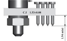
21 Mating dimensions and contact position Female connector Male connector Male connector Female connector Male contact Insulator Female contact Shell Insulator Shell F S Z Min Max Min Max Max 0,22 (.0087) 0,72 (.028) 4,15 (.163) 4,65 (.183) 5,21 (.205) All dimensions in mm (inch) Wiring instructions Insertion and extraction tool: P/N: SMCIET M22500 crimp tool and specific locator: Use standard M22520/2-01 crimp tool with the following locators: Male Female Locator P/N A A AWG Mark n 4 Mark n 4 AWG 28 Mark n 2 Mark n 2 Cable preparation and wire strippping L = Length of wire stripping Contact size L min. L max. # 26 mm (inch) 2,91 (.114) 3,41 (.134) Insertion of wire in contact barrel When inserting the stripped wire into the contact barrel check that no strands are left outside and that the wire is visible through the wire inspection hole in the barrel Conductor insulation 0.5 to 0.8 mm Barrel Wire 21 Inspection hole


22 Wiring instructions Contacts are inserted and extracted from the rear of the connector Insertion of the contacts 1 - Engage the crimp cable / contact assembly into the longitudinal slot of the plastic tool SMCIET (yellow side). Slide the tool down the cable until the tip of the tool abuts the contact retention shoulder Introduce the contact into the required contact cavity in the insulator, pushing the tool axially, until the contact snaps into position in the clip Withdraw the tool (from rear). Check that the contact is firmly locked by pulling the wire gently. When the connector is fully loaded, check the position of the contact tips. They should all be in the same plane. 3- Extraction of the contacts 1 - Engage the appropriate cable into the longitudinal slot of the tool with the blue tip towards the connector Slide the tool down towards the contact. Insert the tool in the insulator until it abuts the contact shoulder Holding the tool-contact and cable assembly together, remove them simultaneously. 3- Please consult ESA ECSS-Q-ST-70-26C and NASA STD recommendations for crimping 22
23 Dimensions Female shell Optional Design Oblong Holes Shell Size H 2.31 ± max (.437 max) 5.05 max (.199 max) ( ) Sealed version (grommet and interfacial seal) Shell Size A B C D E F G H J a b c d e f g h Max Max min Max min Max min Max min Max Max min 10,16 (.400) 13,97 (.550) 17,78 (.634) 20,32 (.700) 24,13 (.950) 27,94 (1.100) 26,67 (.1.050) 38,65 (1.521) 46,80 (1.842) 6,38 (.251) 6,38 (.251) 6,38 (.251) 6,38 (.251) 6,38 (.251) 6,38 (.251) 7,47 (.294) 7,47 (.294) 10,94 (.431) 19,43 (.765) 23,25 (.915) 27,05 (1.065) 29,59 (1.165) 33,41 (1.315) 37,21 (1.465) 35,95 (1.415) 48,05 (1.891) 62,25 (2.451) 19,94 (.785) 23,75 (.935) 27,56 (1.085) 30,10 (1.185) 33,91 (1.335) 37,72 (1.485) 36,45 (1.435) 48,55 (1.911) 62,75 (2.470) 7,31 (.288) 7,31 (.288) 7,31 (.288) 7,31 (.288) 7,31 (.288) 7,31 (.288) 8,42 (.331) 8,42 (.331) 12,00 (.472) 7,82 (.307) 7,82 (.307) 7,82 (.307) 7,82 (.307) 7,82 (.307) 7,82 (.307) 8,92 (.351) 8,92 (.351) 12,50 (.492) 14,22 (.559) 18,03 (.709) 21,84 (.859) 24,38 (.959) 28,19 (1.149) 32,00 (1.259) 30,73 (1.229) 43,23 (1.702) 54,72 (2.154) 14,48 (.570) 18,29 (.720) 22,10 (.870) 24,64 (.970) 28,45 (1.120) 32,26 (1.270) 30,99 (1.220) 43,49 (1.712) 54,98 (1.377) 9,45 (.372) 13,26 (.522) 17,07 (.672) 19,61 (.772) 23,42 (.992) 27,23 (1.072) 25,96 (1.022) 38,40 (1.512) 47,40 (1.866) 10,16 (.400) 13,97 (.550) 17,78 (.700) 20,32 (.800) 24,13 (.950) 27,94 (1.100) 26,67 (1.050) 38,65 (1.522) 47,65 (1.876) 6,86 (.270) 6,86 (.270) 6,86 (.270) 6,86 (.270) 6,86 (.270) 6,86 (.270) 6,86 (.270) 7,87 (.310) 11,25 (.443) 2,26 (.089) 2,26 (.089) 2,26 (.089) 2,26 (.089) 2,26 (.089) 2,26 (.089) 2,26 (.289) 2,26 (.089) 3,70 (.146) All dimensions in mm (inches) 23
 Shell size A B C D E F G H J a b c d e f g h Max Max min Max min Max min Max min Max Max min 8,48 (.334) 12,29 (.484) 16,10 (.634) 18,64 (.734) 22,45 (.")
 27,05 (1.065) 29,59 (1.165) 33,41 (1.315) 37,21 (1.465) 35,95 (1.415) 48,05 (1.891) 62,25 (2.451) 19,94 (.785) 23,75 (.935) 27,56 (1.085) 30,10 (1.185) 33,91 (1.335) 37,72 (1.485) 36,45 (1.")
24 Dimensions Male shell Optional Design Oblong Holes Shell Size H max (.426 max) ( ) 4.42 max (.174 max) 2.31 ± Sealed version (with grommet) Shell size A B C D E F G H J a b c d e f g h Max Max min Max min Max min Max min Max Max min 8,48 (.334) 12,29 (.484) 16,10 (.634) 18,64 (.734) 22,45 (.884) 26,26 (1.034) 24,99 (.934) 36,90 (1.463) 45,10 (1.775) 4,69 (.185) 4,69 (.185) 4,69 (.185) 4,69 (.185) 4,69 (.185) 4,69 (.185) 4,69 (.185) 5,78 (.227) 9,25 (.364) 19,43 (.765) 23,25 (.915) 27,05 (1.065) 29,59 (1.165) 33,41 (1.315) 37,21 (1.465) 35,95 (1.415) 48,05 (1.891) 62,25 (2.451) 19,94 (.785) 23,75 (.935) 27,56 (1.085) 30,10 (1.185) 33,91 (1.335) 37,72 (1.485) 36,45 (1.435) 48,55 (1.911) 62,75 (2.470) 7,31 (.288) 7,31 (.288) 7,31 (.288) 7,31 (.288) 7,31 (.288) 7,31 (.288) 7,31 (.288) 8,42 (.331) 12,00 (.472) 7,82 (.307) 7,82 (.307) 7,82 (.307) 7,82 (.307) 7,82 (.307) 7,82 (.307) 7,82 (.307) 8,92 (.351) 12,50 (.492) 14,22 (.559) 18,03 (.709) 21,84 (.859) 24,38 (.959) 29,19 (1.149) 32,00 (1.259) 30,73 (1.209) (1.702) 54,72 (2.154) 14,48 (.570) 18,29 (.720) 22,10 (.870) 24,64 (.970) 28,45 (1.120) 32,26 (1.270) 30,99 (1.220) 43,49 (1.712) 54,98 (1.377) 9,45 (.372) 13,26 (.522) 17,07 (.672) 19,61 (.772) 23,42 (.992) 27,23 (1.072) 25,96 (1.022) 38,40 (1.512) 47,40 (1.866) 10,16 (.400) 13,97 (.550) 17,78 (.700) 20,32 (.800) 24,13 (.950) 27,94 (1.100) 26,67 (1.050) 38,65 (1.522) 47,65 (1.876) 6,86 (.270) 6,86 (.270) 6,86 (.270) 6,86 (.270) 6,86 (.270) 6,86 (.270) 6,86 (.270) 7,87 (.310) 11,25 (.443) 2,26 (.089) 2,26 (.089) 2,26 (.089) 2,26 (.089) 2,26 (.089) 2,26 (.089) 2,26 (.089) 2,26 (.089) 3,70 (.146) All dimensions in mm (inches) 24


 All dimensions in mm")

 25")
25 Dimensions PCB versions male connectors P1AON Straight - All shell sizes 90 - Shell sizes G and H 90 - shell sizes A to F 90 - Shell size J X=2.54 (.1) All dimensions in mm (inches) PCB versions male connectors with mounting accessories P1A7N Straight - All shell sizes 90 - Shell sizes G and H 90 - shell sizes A to F 90 - Shell size J X=2.54 (.1) All dimensions in mm (inches) 25
 Option 1: Front mounting on panel Jackpost Jackscrew Mounting hardware for front mounting on panel: Standard Jackpost (not for rear panel mounting) Space Grade (SOURIAU P/N)")
26 Mounting operations and hardware Double panel mounting dimensions For hardware dimensions consult the mounting hardware section. Dimensions in mm (inches) Option 1: Front mounting on panel Jackpost Jackscrew Mounting hardware for front mounting on panel: Standard Jackpost (not for rear panel mounting) Space Grade (SOURIAU P/N) Individual packaging (one package for one mated pair) Type P/N Description Size A-H Size J 8MCJP507NM 8MCJP517NM Jackpost Kit for microcomp shell size A to H (2 jackposts + 2 washers + 2 nuts). Front panel or cable-to-cable mounting. Jackpost Kit for microcomp shell size J (2 jackposts + 2 washers + 2 nuts). Front panel or cable-to-cable mounting. Standard Jackpost (not for rear panel mounting) Space Grade (SOURIAU P/N) Packaging per 50 kits (one package for 50 mated pair) Type P/N Description Size A-H Size J 8MCJP507NM50 8MCJP517NM50 Jackpost Kit for microcomp shell size A to H (100 jackposts washers nuts). Front panel or cable-to-cable mounting. Jackpost Kit for microcomp shell size J (100 jackposts washers nuts). Front panel or cable-to-cable mounting. 26
. Front panel or cable-to-cable mounting.")
27 Option 1: Front mounting on panel Standard Jackpost (not for rear panel mounting) ESA P/N Individual packaging (two packages for one mated pair) Type P/N Description Size A-H Size J Jackpost Kit for microcomp shell size A to H (1 jackpost + 1 washer + 1 nut). Front panel or cable-to-cable mounting. Jackpost Kit for microcomp shell size J (1 jackpost + 1 washer + 1 nut). Front panel or cable-to-cable mounting. Option 2: Rear mounting on panel With additional mounting on PCB: combined Option 2 and Option 3 Mounting hardware for rear mounting on panel for panel thickness from 0.8 mm to 3.2 mm. Jackpost for rear panel mounting Space Grade (SOURIAU P/N) Individual packaging (one package for one mated pair) Type P/N Panel Description Size A-H Size J 8MCJP008NM 8MCJP012NM 8MCJP016NM 8MCJP024NM 8MCJP032NM 8MCJP508NM 8MCJP512NM 8MCJP516NM 8MCJP524NM 0,8 mm (.031 in) 1,2 mm (.047 in) 1,6 mm (.063 in) 2,4 mm (.094 in) 3,2 mm (.126 in) 0,8 mm (.031 in) 1,2 mm (.047 in) 1,6 mm (.063 in) 2,4 mm (.094 in) Jackpost Kit for microcomp shell size A to H (2 jackposts + 2 washers + 2 nuts). Jackpost Kit for microcomp shell size A to H (2 jackposts + 2 washers + 2 nuts). Jackpost Kit for microcomp shell size A to H (2 jackposts + 2 washers + 2 nuts). Jackpost Kit for microcomp shell size A to H (2 jackposts + 2 washers + 2 nuts). Jackpost Kit for microcomp shell size A to H (2 jackposts + 2 washers + 2 nuts). Jackpost Kit for microcomp shell size J ( 2 jackposts + 2 washers + 2 nuts). Jackpost Kit for microcomp shell size J (2 jackposts + 2 washers + 2 nuts). Jackpost Kit for microcomp shell size J (2 jackposts + 2 washers + 2 nuts). Jackpost Kit for microcomp shell size J (2 jackposts + 2 washers + 2 nuts). 8MCJP532NM 3,2 mm (.126 in) Jackpost Kit for microcomp shell size J (2 jackposts + 2 washers + 2 nuts). 27
 Type P/N Panel Description Size A-H Size J 8MCJP008NM50 8MCJP012NM50 8MCJP016NM50 8MCJP024NM50 8MCJP032NM50 8MCJP508NM50 8MCJP512NM50 8MCJP516NM50")
28 Mounting operations and hardware Option 2: Rear mounting on panel With additional mounting on PCB: combined Option 2 and Option 3 Jackpost for rear panel mounting Space Grade (SOURIAU P/N) Packaging per 50 kits (one package for 50 mated pairs) Type P/N Panel Description Size A-H Size J 8MCJP008NM50 8MCJP012NM50 8MCJP016NM50 8MCJP024NM50 8MCJP032NM50 8MCJP508NM50 8MCJP512NM50 8MCJP516NM50 8MCJP524NM50 0,8 mm (.031 in) 1,2 mm (.047 in) 1,6 mm (.063 in) 2,4 mm (.094 in) 3,2 mm (.126 in) 0,8 mm (.031 in) 1,2 mm (.047 in) 1,6 mm (.063 in) 2,4 mm (.094 in) Jackpost Kit for microcomp shell size A to H (100 jackposts washers nuts). Jackpost Kit for microcomp shell size A to H (100 jackposts washers nuts). Jackpost Kit for microcomp shell size A to H (100 jackposts washers nuts). Jackpost Kit for microcomp shell size A to H (100 jackposts washers nuts). Jackpost Kit for microcomp shell size A to H (100 jackposts washers nuts). Jackpost Kit for microcomp shell size J (100 jackposts washers nuts). Jackpost Kit for microcomp shell size J (100 jackposts washers nuts). Jackpost Kit for microcomp shell size J (100 jackposts washers nuts). Jackpost Kit for microcomp shell size J (100 jackposts washers nuts). 8MCJP532NM50 3,2 mm (.126 in) Jackpost Kit for microcomp shell size J (100 jackposts washers nuts). Option 3: Mounting on PCB with 90 bent contacts Solder the connector contacts to the PCB Screw the connector to the PCB Optional: break the sides of the plastic drilled bar and remove all parts of the bar Break these parts 28
29 With additional rear mounting on panel: combined Option 2 and Option 3. Removable drilled bar Panel PCB Bracket Jackpost Mounting hardware for mounting on PCB with 90 bent contacts Standard Jackpost (not for rear panel mounting) Brackets: to fix the receptacle on the PCB Space Grade (SOURIAU P/N) Individual packaging (one package for one mated pair) Type P/N Description Size A-H Size J 8MCJP507NM 8MCJP517NM Jackpost Kit for microcomp shell size A to H (2 jackposts + 2 washers + 2 nuts). Front panel or cable-to-cable mounting. Jackpost Kit for microcomp shell size J (2 jackposts + 2 washers + 2 nuts). Front panel or cable-to-cable mounting. Size A-F 8MCBKAFNM Bracket kit for shell size A to F (2 brackets). Not for sealed version. Size G-H 8MCBKGHNM Bracket kit for shell size G and H (2 brackets). Not for sealed version. Size J 8MCBKJNM Bracket kit for shell size J (2 brackets). Not for sealed version. Standard Jackpost (not for rear panel mounting) Brackets: to fix the receptacle on the PCB Space Grade (SOURIAU P/N) Packaging per 50 kits (one package for 50 mated pairs) Type P/N Description Size A-H Size J 8MCJP507NM50 8MCJP517NM50 Jackpost Kit for microcomp shell size A to H (100 jackposts washers nuts). Front panel or cable-to-cable mounting. Jackpost Kit for microcomp shell size J (100 jackposts washers nuts). Front panel or cable-to-cable mounting. Size A-F 8MCBKAFNM50 Bracket kit for shell size A to F (100 brackets). Not for sealed version. Size G-H 8MCBKGHNM50 Bracket kit for shell size G and H (100 brackets). Not for sealed version. Size J 8MCBKJNM50 Bracket kit for shell size J (100 brackets). Not for sealed version. Standard Jackpost (not for rear panel mounting) ESA P/N Individual packaging (two packages for one mated pair) Type P/N Description Size A-H Size J B B Jackpost Kit for microcomp shell size A to H (1 jackpost + 1 washer + 1 nut). Front panel or cable-to-cable mounting. Jackpost Kit for microcomp shell size J (1 jackpost + 1 washer + 1 nut). Front panel or cable-to-cable mounting. 29
 Type P/N Description Jackpost for PCB mounting (straight spills/ PC tails) Size A-H Size J 8MCJPS070NM 8MCJPS170NM Jackpost kit for straight spills / PC tails")
30 Mounting operations and hardware Option 4: Mounting on PCB with straight PCB contacts Mounting hardware for mounting on PCB with straight PCB contacts Space Grade (SOURIAU P/N) Individual packaging (one package for one mated pair) Type P/N Description Jackpost for PCB mounting (straight spills/ PC tails) Size A-H Size J 8MCJPS070NM 8MCJPS170NM Jackpost kit for straight spills / PC tails microcomp shell size A to H (2 jackposts + 2 spacers + 2 washers + 2 nuts). For mounting on PCB. Jackpost kit for straight spills / PC tails microcomp shell size J (2 jackposts + 2 spacers + 2 washers + 2 nuts). For mounting on PCB. Space Grade (SOURIAU P/N) Packaging per 50 kits (one package for 50 mated pairs) Type P/N Description Jackpost for PCB mounting (straight spills/ PC tails) Size A-H Size J 8MCJPS070NM50 8MCJPS170NM50 Jackpost kit for straight spills / PC tails version shell size A to H (100 jackposts washers nuts). For mounting on PCB. Jackpost kit for straight spills / PC tails shell size J (100 jackposts washers nuts). For mounting on PCB. 30
31 Panel cut-out Shell size A B C D E F G H J Mounting option a +0.1 (+.004) -0.0 (.000) Cut-out dimensions in mm (inch) b +0.1 (+.004) -0.0 (.000) c +0.1 (+.004) -0.1 (-.004) 31 d +0.1 (+.004) -0.0 (.000) (.408) 6.88 (.270) (.565) 2.26 (.089) (.401) 6.40 (.252) (.565) 2.26 (.089) 3 & (.401) 6.40 (.252) (.565) 3.70 (.146) (.558) 6.88 (.270) (.731) 2.26 (.089) (.551) 6.40 (.252) (.731) 2.26 (.089) 3 & (.551) 6.40 (.252) (.731) 3.70 (.146) (.708) 6.88 (.270) (.865) 2.26 (.089) (.701) 6.40 (.252) (.865) 2.26 (.089) 3 & (.701) 6.40 (.252) (.865) 3.70 (.146) (.808) 6.88 (.270) (.965) 2.26 (.089) (.801) 6.40 (.252) (.965) 2.26 (.089) 3 & (.801) 6.40 (.252) (.965) 3.70 (.146) (.958) 6.88 (.270) (1.115) 2.26 (.089) (.951) 6.40 (.252) (1.115) 2.26 (.089) 3 & (.951) 6.40 (.252) (1.115) 3.70 (.146) (1.108) 6.88 (.270) (1.265) 2.26 (.089) (1.101) 6.40 (.252) (1.265) 2.26 (.089) 3 & (1.101) 6.40 (.252) (1.265) 3.70 (.146) (1.058) 8.00 (.315) (1.215) 2.26 (.089) (1.051) 7.49 (.295) (1.215) 2.26 (.089) 3 & (1.051) 7.49 (.295) (1.215) 3.70 (.146) (1.537) 8.00 (.315) (1.707) 2.26 (.089) (1.522) 7.49 (.295) (1.707) 2.26 (.089) 3 & (1.522) 7.49 (.295) (1.707)) 3.70 (.146) (1.892) (.449) (2.159) 3.20 (.126) (1.842) (.437) (2.159) 3.20 (.126) 3 & (1.842) (.437) (2.159) 5.60 (.220) All dimensions in mm (inches)
 1 (.039) 2 (.079) +0.13 Ø 2.26 0 ( Ø.089 +.005 0 ) 1 (.039) 2 (.079) 18.16 (.715) 30.86 (1.21) B 11 2 (.079) G 33 2 (.079) +0.13 Ø 2.26 0 ( Ø.089 +.005 0 ) 1 (.039) 2 (.079) +0.13 Ø 2.26 0 ( Ø.089 +.005 0 ) 1 (.039) 2 (.079) 21.")
32 PCB drilling Shell size Number of contacts Drilling dimensions Shell size Number of contacts Drilling dimensions (.565) (1.26) A 7 2 (.079) F 25 2 (.079) Ø ( Ø ) 1 (.039) 2 (.079) Ø ( Ø ) 1 (.039) 2 (.079) (.715) (1.21) B 11 2 (.079) G 33 2 (.079) Ø ( Ø ) 1 (.039) 2 (.079) Ø ( Ø ) 1 (.039) 2 (.079) (.865) (1.707) C Ø ( Ø ) 2 (.079) 1 (.039) 2 (.079) H Ø Ø ) ( 2 (.079) 1 (.039) 2 (.079) (.965) (2.16) D 17 2 (.079) J (.079) Ø ( Ø ) 1 (.039) 2 (.079) Ø ( Ø ) 1 (.039) 2 (.079) (1.12) 2 (.079) E Ø ( Ø ) 1 (.039) 2 (.079) X Y OL (.068) (.136) 1AON (.1) 5.08 (.2) All dimensions in mm (inches) Note: we suggest 0.89 (.035) Ø hole for contact termination positions on PCB (0.50 (.020) Ø spills). 32
 P/N for packaging per 50 (one package for 50 mated pair: 100 brackets) A to F 8MCBKAFNM 8MCBKAFNM50 G and H")
 UNC-2B 16.90 9.10 5.6±0.10 10.44±0.10 4.0±0.10 3.15 2.44 ±0.10 #20-56 (.665 ) (.359 ) (.220 ±.004) (.411 ±.004) (.158 ±.004) (.124 ) (.096 ±.004) UNC-2B 23.10 13.10 7.35±0.10 13.13±0.10 6.")
33 Mounting hardware Brackets for mounting on PCB with 90 bent contacts Shell size A to H J Min (Nm) Max (Nm) Min (Nm) Max (Nm) Torque value For shell size P/N for individual packaging (one package for one mated pair: 2 brackets) P/N for packaging per 50 (one package for 50 mated pair: 100 brackets) A to F 8MCBKAFNM 8MCBKAFNM50 G and H 8MCBKGHNM 8MCBKGHNM50 J 8MCBKJNM 8MCBKJNM50 A max B max C D E F max G H ± ± ± ±0.10 #20-56 (.555 ) (.338 ) (.197±.004) (.361 ±.004) (.158 ±.004) (.124 ) (.096 ±.004) UNC-2B ± ± ± ±0.10 #20-56 (.665 ) (.359 ) (.220 ±.004) (.411 ±.004) (.158 ±.004) (.124 ) (.096 ±.004) UNC-2B ± ± ± ±0.15 #20-56 (.909 ) (.515 ) (.290 ±.004) (.516 ±.004) (.256 ±.004) (.165 ) (.124 ±.006) UNC-2B All dimensions in mm (inches) Standard Jackpost Shell size A to H J Torque Values Min (Nm) Max (Nm) Min (Nm) Max (Nm) Jackpost male side Jackpost female side Nut
 Lock washer NASM35338-134 NASM35338-135 Material & Finish Individual packaging Souriau Space Grade (one package for one mated pair: 2 posts, 2 washers and 2 nuts) 303 stainless steel, passivated")
 Torque values: same as \"Standard Jackposts\" Lock Washer Panel thickness A thread size B thread")
34 Mounting hardware Standard Jackpost For shell size A to H J A thread size #2-56 UNC #4-40 UNC B hex size in mm (inch) 3,18 (.125) 4,75 (.187) Lock washer NASM NASM Material & Finish Individual packaging Souriau Space Grade (one package for one mated pair: 2 posts, 2 washers and 2 nuts) 303 stainless steel, passivated per QQ-P-35 8MCJP507NM 8MCJP517NM ESA P/N (1 post + 1 washer + 1 nut) B B P/N for packaging per 50 kits (one package for 50 mated pair: 100 posts, 100 washers and 100 nuts) 8MCJP507NM50 8MCJP517NM50 Jackposts for rear panel mounting Jackpost Nut All dimensions in mm (inches) Torque values: same as "Standard Jackposts" Lock Washer Panel thickness A thread size B thread size 0,8 mm (.031 in) For shell size A to H 1,2 mm (.047 in) 1,6 mm (.063 in) #2-56 UNC-2B #2-56 UNC-2A C max Ø 3,0 (.118) D max Ø 4,1 (.161) E 4,70/4,83 (.185/.190) 2,4 mm (.094 in) 3,2 mm (.126 in) F max 0,615 (.002) 1,09 (.042) 1,45 (.057) 2,23 (.087) 3,05 (.120) G max 1.67 (.066) H max 4,0 (.157) Lock washer Material & Finish P/N for individual packaging (one package for one mated pair: 2 posts, 2 washers and 2 nuts) NASM stainless steel, passivated per QQ-P-35 8MCJP008NM 8MCJP012NM 8MCJP016NM 8MCJP024NM 8MCJP032NM P/N for packaging per 50 kits (one package for 50 mated pair: 100 posts, 100 washers and 100 nuts) 8MCJP008NM50 8MCJP012NM50 8MCJP016NM50 8MCJP024NM50 8MCJP032NM50 34
35 Jackposts for rear panel mounting Panel thickness A thread size B thread size 0,8 mm (.031 in) For shell size J 1,2 mm (.047 in) 1,6 mm (.063 in) #4-40 UNC-2B #4-40 UNC-2A C max Ø 3,6 (.141) D max Ø 4,71 (.185) E 4,45/4,70 (.175/.185) 2,4 mm (.094 in) 3,2 mm (.126 in) F max 0,615 (.002) 1,09 (.042) 1,45 (.057) 2,23 (.087) 3,05 (.120) G max 1.67 (.066) H max 4,0 (.157) Lock washer Material & Finish P/N for individual packaging (one package for one mated pair: 2 posts, 2 washers and 2 nuts) P/N for packaging per 50 kits (one package for 50 mated pair: 100 posts, 100 washers and 100 nuts) NASM stainless steel, passivated per QQ-P-35 8MCJP008NM 8MCJP512NM 8MCJP516NM 8MCJP524NM 8MCJP532NM 8MCJP508NM50 8MCJP512NM50 8MCJP516NM50 8MCJP524NM50 8MCJP532NM50 35
 3,18 (.125) 4,75 (.")
 P/N for packaging per 50 kits (one package for 50 mated pair: 100 posts, 100 washers and 100 nuts) 8MCJPS070NM 8MCJPS070NM50 303 stainless steel,")
36 Mounting hardware Jackposts for PCB mounting (straight spills/pc tails): Jackpost Spacer Nut Lock Washer Torque values: same as "Standard Jackposts" For shell size A to H J A thread size #2-56 UNC #4-40 UNC B hex size in mm (inch) 3,18 (.125) 4,75 (.187) Lock washer NASM NASM Material & Finish P/N for individual packaging (one package for one mated pair: 2 posts, 2 washers and 2 nuts) P/N for packaging per 50 kits (one package for 50 mated pair: 100 posts, 100 washers and 100 nuts) 8MCJPS070NM 8MCJPS070NM stainless steel, passivated per QQ-P-35 8MCJPS170NM 8MCJPS170NM50 Jackpost Spacer 36
37 Standard Jackscrews Torque values: same as "Standard Jackposts" For shell size A to H J #2-56 UNC #4-40 UNC Dimensions in mm (inch) Head type Allen head Slot head Allen head Slot head Material & Finish P/N for individual packaging (one package for one mated pair: 2 screws and 2 e-rings) ESA P/N (1 screw and 1 e-rings) P/N for packaging per 50 kits (one package for 50 mated pair: 100 screws and 100 e-rings) 303 stainless steel, passivated per QQ-P-35 8MCJS502NM 8MCJS505NM 8MCJS512NM 8MCJS515NM B B B B 8MCJS502NM50 8MCJS505NM50 8MCJS512NM50 8MCJS515NM50 37
 20.32 (.700) 24.13 (.950) 27.94 (1.100) 26.67 (1.050) 38.65 (1.521) 46.80 (1.842) 6.38 (.251) 6.38 (.251) 6.38 (.251) 6.38 (.251) 6.38 (.251) 6.38 (.251) 7.47 (.294) 7.47 (.294) 10.94 (.431) 19.")
 36.45 (1.435) 48.55 (1.911) 62.75 (2.470) 7.31 (.288) 7.31 (.288) 7.31 (.288) 7.31 (.288) 7.31 (.288) 7.31 (.288) 8.42 (.331) 8.42 (.331) 12.00 (.472) 7.82 (.307) 7.82 (.307) 7.82 (.307) 7.82 (.307) 7.82 (.307) 7.82 (.307) 8.")
38 Savers Physical informations Jackpost (ordered separately) Retaining ring Shell Size A B C D E F G H J a b c d e f g h Max Max min Max min Max min Max Max Max min (.400) (.550) (.634) (.700) (.950) (1.100) (1.050) (1.521) (1.842) 6.38 (.251) 6.38 (.251) 6.38 (.251) 6.38 (.251) 6.38 (.251) 6.38 (.251) 7.47 (.294) 7.47 (.294) (.431) (.765) (.915) (1.065) (1.165) (1.315) (1.465) (1.415) (1.891) (2.451) (.785) (.935) (1.085) (1.185) (1.335) (1.485) (1.435) (1.911) (2.470) 7.31 (.288) 7.31 (.288) 7.31 (.288) 7.31 (.288) 7.31 (.288) 7.31 (.288) 8.42 (.331) 8.42 (.331) (.472) 7.82 (.307) 7.82 (.307) 7.82 (.307) 7.82 (.307) 7.82 (.307) 7.82 (.307) 8.92 (.351) 8.92 (.351) (.492) (.559) (.709) (.859) (.959) (1.149) (1.259) (1.209) (1.682) (2.154) (.570) (.720) (.870) (.970) (1.120) (1.270) (1.220) (1.692) (1.377) 8.48 (.334) (.484) (.634) (.734) (.884) (1.034) (.934) (1.463) (1.775) 4.69 (.185) 4.69 (.185) 4.69 (.185) 4.69 (.185) 4.69 (.185) 4.69 (.185) 4.69 (.185) 5.78 (.227) 9.25 (.364) 2.26 (.089) 2.26 (.089) 2.26 (.089) 2.26 (.089) 2.26 (.089) 2.26 (.089) 2.26 (.089) 2.26 (.089) 3.70 (.146) Jackpost Retaining ring Size A to H Size J 41
39 Savers Ordering informations microcomp savers series part numbering 8MCS G A7 PS Shell Material Version: Shell size & contacts layout: Pin socket contacts: * Consult us for availability Jackpost kits are never included None: composite A: Aluminum G: Gold plating N: Nickel plating None: without plating A7: 7 contacts B11: 11 contacts* C13: 13 contacts D17: 17 contacts* E21: 21 contacts* F25: 25 contacts G33: 33 contacts* H51: 51 contacts J104: 104 contacts PS: male/female Space Grade (SOURIAU P/N) Individual packaging (one package for one mated pair) Type P/N Description Jackposts Size A-H 8MCJPA507NM Jackpost Kit for microcomp savers shell size A to H (2 jackposts + 2 e-ring). for savers Size J 8MCJPA517NM Jackpost Kit for microcomp savers shell size J (2 jackposts + 2 e-ring). Jackposts for savers Space Grade (SOURIAU P/N) Packaging per 50 kits (one package for 50 mated pair) Type P/N Description Size A-H Size J 8MCJPA507NM50 8MCJPA517NM50 Jackpost Kit for microcomp savers shell size A to H (100 jackposts e-ring). Jackpost Kit for microcomp savers shell size J (100 jackposts e-ring). 42

40 EMI Backshells Technical features SOURIAU Space Grade backshell kits consist of one low profile machined aluminum alloy backshell gold plated, two jackscrews (or jackposts) and two clips. Cable exits are designed for banded clamp termination. Once the braided copper shield is secure to the backshell the cable can be terminated with an heatshrink boot. Available with circular and/or elliptical entry, depending on shell size. Available with straight, 45 and 90 entry. For cable-to-box or cable-to-cable connection (for one cable-to-cable assembly, order one backshell with jackpost and one with jackscrew). Finish: 0.7 µm minimum of gold over a copper or electroless nickel base layer with a minimum thickness of 10 µm. Jackscrew Backshell Clip Connector Cable entry size Each backshell is available with 2 entry sizes, circular and/or elliptical Shell size A-B C-D E-F G H J Entry code Entry shape Circular entry size in mm (inch) ø g Elliptical entry size in mm (inch) x ±0.15 (±.060) y ±0.15(±.060) Entry surface in mm² (inch²) 02 Circular 3,20 (.126) (.012) 03 Circular 4,80 (.189) (.028) 03 Circular 4,80 (.189) (.028) 04 Circular 6,40 (.252) (.05) 03 Circular 4,80 (.189) (.028) 05 Elliptical (.425) 5.80 (.229) 49.2 (.076) 04 Circular 6,40 (.252) (.05) 06 Circular 9,50 (.374) (.110) 05 Elliptical - 10,80 (.425) 5.80 (.229) 49.2 (.076) 07 Elliptical - 21,00 (.827) 5.8 (.228) 95.7 (.148) 08 Elliptical - 23,50 (.925) 6.80 (.268) (.195) 10 Elliptical - 33,00 (1.3) 7.8 (.307) (.313) 43
 F: jackposts (for cable to cable connection only) Backshells are always supplied with 2 clips and")
41 EMI Backshells Straight backshell Straight backshell 8MCBS F G Shell size: A - B - C - D - E - F - G - H - J Environment: None: for connector without grommet Straight version: 001 Cable entry type: see «Cable entry size» table Finish: G: gold Mounting hardware: None: jackscrews (standard use) F: jackposts (for cable to cable connection only) Backshells are always supplied with 2 clips and 2 jackscrews or jackposts Circular entry Elliptical entry Shell Size A B C D E F G H J a ±0.15 (±.060) b ±0.13 (±.051) c ±0.15 (±.060) d Max. e Max. 19,70 (.776) 14,35 (.565) 9,00 (.354) 10,00 (.394) 23,40 (.921) 18,16 (.715) 9,00 (.354) 12,00 (.472) 27,30 (1.075) 21,97 (.865) 9,00 (.354) 14,00 (.551) 29,85 (1.176) 24,51 (.965) 9,00 (.354) 16,00 (.623) 33,70 (1.327) 28,32 (1.115) 9,00 (.354) 17,00 (.670) 37,50 (1.476) 32,13 (1.265) 9,00 (.354) 18,00 (.709) 36,10 (1.421) 30,86 (1.215) 10,00 (.394) 19,00 (.748) (1.923) (1.707) 10,00 (.395) 19,00 (.748) (2.473) (2.160) 13,00 (.512) 21,00 (.827) Max weight in g (oz) 3,50 (0.12) 3,80 (0.13) 5,00 (0.18) 5,60 (0.20) 7,00 (0.25) 7,70 (0.27) 9,20 (0.32) 9,50 (0.34) 14,50 (0.51) All dimensions in mm (inches) 44
 F: jackposts (for cable to cable connection only) Backshells are always supplied with 2 clips and 2 jackscrews or jackposts")
 18,16 (.715) 9,00 (.354) 12,00 (.472) 23,00 (.906) 27,30 (1.075) 21,97 (.865) 9,00 (.354) 14,00 (.551) 25,00 (.984) 29,85 (1.176) 24,51 (.965) 9,00 (.354) 16,00 (.623) 27,00 (1.063) 33,70 (1.")
42 45 backshell 45 backshell 8MCBS F G Shell size: A - B - C - D - E - F - G - H - J Environment: None: for connector without grommet 45 version: 101 Cable entry type: see «Cable entry size» table Finish: G: gold Mounting hardware: None: jackscrews (standard use) F: jackposts (for cable to cable connection only) Backshells are always supplied with 2 clips and 2 jackscrews or jackposts Circular entry Elliptical entry Shell Size A B C D E F G H J a ±0.15 (±.060) b ±0.13 (±.051) c ±0.15 (±.060) d Max. f Max. 19,70 (.776) 14,35 (.565) 9,00 (.354) 10,00 (.394) 21,00 (.827) 23,40 (.921) 18,16 (.715) 9,00 (.354) 12,00 (.472) 23,00 (.906) 27,30 (1.075) 21,97 (.865) 9,00 (.354) 14,00 (.551) 25,00 (.984) 29,85 (1.176) 24,51 (.965) 9,00 (.354) 16,00 (.623) 27,00 (1.063) 33,70 (1.327) 28,32 (1.115) 9,00 (.354) 17,00 (.670) 28,00 (1.102) 37,50 (1.476) 32,13 (1.265) 9,00 (.354) 18,00 (.709) 29,00 (1.142) 36,10 (1.421) 30,86 (1.215) 10,00 (.394) 19,00 (.748) 30,00 (1.181) (1.923) (1.707) 10,00 (.395) 23,00 (.905) 30,00 (1.058) (2.473) (2.160) 13,00 (.512) 25,00 (.984) 38,00 (1.340) Max weight in g (oz) 5,20 (0.18) 6,20 (0.22) 7,35 (0.26) 8,45 (0.30) 9,25 (0.33) 10,70 (0.38) 11,45 (0.40) 12,00 (0.42) (0.67) All dimensions in mm (inches) 45
 F: jackposts (for cable to cable connection only) Backshells are always supplied with 2 clips and 2 jackscrews or")
 9,00 (.354) 12,00 (.472) 27,30 (1.075) 21,97 (.865) 9,00 (.354) 14,00 (.551) 29,85 (1.176) 24,51 (.965) 9,00 (.354) 16,00 (.623) 33,70 (1.327) 28,32 (1.115) 9,00 (.354) 17,00 (.670) 37,50 (1.")
43 EMI Backshells 90 backshell 90 backshell 8MCBS F G Shell size: A - B - C - D - E - F - G - H - J Environment: None: for connector without grommet 90 version: 201 Cable entry type: see «Cable entry size» table Finish: G: gold Mounting hardware: None: jackscrews (standard use) F: jackposts (for cable to cable connection only) Backshells are always supplied with 2 clips and 2 jackscrews or jackposts Circular entry Elliptical entry Shell Size A B C D E F G H J a ±0.15 (±.060) b ±0.13 (±.051) c ±0.15 (±.060) d Max. 19,70 (.776) 14,35 (.565) 9,00 (.354) 10,00 (.394) 23,40 (.921) 18,16 (.715) 9,00 (.354) 12,00 (.472) 27,30 (1.075) 21,97 (.865) 9,00 (.354) 14,00 (.551) 29,85 (1.176) 24,51 (.965) 9,00 (.354) 16,00 (.623) 33,70 (1.327) 28,32 (1.115) 9,00 (.354) 17,00 (.670) 37,50 (1.476) 32,13 (1.265) 9,00 (.354) 18,00 (.709) 36,10 (1.421) 30,86 (1.215) 10,00 (.394) 19,00 (.748) (1.923) (1.707) 10,00 (.395) 23,00 (.905) (2.473) (2.160) 13,00 (.512) 25,00 (.984) Max weight in g (oz) 5,13 (0.18) 6,20 (0.22) 7,31 (0.26) 8,44 (0.30) 9,25 (0.33) 10,44 (0.38) 11,44 (0.40) 12,00 (0.42) (0.67) All dimensions in mm (inches) 46
44 ESA part numbers ESA series - EMI Backshells B Variant: See table below Testing Level B Cross-reference ESA / SOURIAU part numbers SOURIAU P/N ESA P/N Description Max weight in g (w/o clip, jackpost, jackscrew) 8MCBS A G B Straight with male jackscrews and clips, size A 2,7 8MCBS B G B Straight with male jackscrews and clips, size B 3 8MCBS C G B Straight with male jackscrews and clips, size C 3,95 8MCBS D G B Straight with male jackscrews and clips, size D 4,75 8MCBS E G B Straight with male jackscrews and clips, size E 5,5 8MCBS F G B Straight with male jackscrews and clips, size F 6,15 8MCBS G G B Straight with male jackscrews and clips, size G 7,35 8MCBS A G F B Straight with female jackposts, size A 2,7 8MCBS B G F B Straight with female jackposts, size B 3 8MCBS C G F B Straight with female jackposts, size C 3,95 8MCBS D G F B Straight with female jackposts, size D 4,75 8MCBS E G F B Straight with female jackposts, size E 5,5 Size A to G 8MCBS F G F B Straight with female jackposts, size F 6,15 8MCBS G G F B Straight with female jackposts, size G 7,35 8MCBS A G B 45 with male jackscrews and clips, size A 4,1 8MCBS B G B 45 with male jackscrews and clips, size B 4,95 8MCBS C G B 45 with male jackscrews and clips, size C 5,85 8MCBS D G B 45 with male jackscrews and clips, size D 6,75 8MCBS E G B 45 with male jackscrews and clips, size E 7,4 8MCBS F G B 45 with male jackscrews and clips, size F 8,55 8MCBS G G B 45 with male jackscrews and clips, size G 9,15 8MCBS A G F B 45 with female jackposts, size A 4,1 8MCBS B G F B 45 with female jackposts, size B 4,95 8MCBS C G F B 45 with female jackposts, size C 5,85 8MCBS D G F B 45 with female jackposts, size D 6,75 8MCBS E G F B 45 with female jackposts, size E 7,4 8MCBS F G F B 45 with female jackposts, size F 8,55 8MCBS G G F B 45 with female jackposts, size G 9,15 47
45 EMI Backshells Cross-reference ESA / SOURIAU part numbers SOURIAU P/N ESA P/N Description Max weight in g (w/o clip, jackpost, jackscrew) 8MCBS A G B 90 with male jackscrews and clips, size A 4,1 8MCBS B G B 90 with male jackscrews and clips, size B 4,95 8MCBS C G B 90 with male jackscrews and clips, size C 5,85 8MCBS D G B 90 with male jackscrews and clips, size D 6,75 8MCBS E G B 90 with male jackscrews and clips, size E 7,4 Size A to G 8MCBS F G B 90 with male jackscrews and clips, size F 8,35 8MCBS G G B 90 with male jackscrews and clips, size G 9,15 8MCBS A G F B 90 with female jackposts, size A 4,1 8MCBS B G F B 90 with female jackposts, size B 4,95 8MCBS C G F B 90 with female jackposts, size C 5,85 8MCBS D G F B 90 with female jackposts, size D 6,75 8MCBS E G F B 90 with female jackposts, size E 7,4 8MCBS F G F B 90 with female jackposts, size F 8,35 8MCBS G G F B 90 with female jackposts, size G 9,15 8MCBS H G B Straight with male jackscrews and clips, size H 7,5 8MCBS J G B Straight with male jackscrews and clips, size J 11,5 8MCBS H G F B Straight with female jackposts, size H 7,5 8MCBS J G F B Straight with female jackposts, size J 11,5 Size H and J 8MCBS H G B 45 with male jackscrews and clips, size H 9,5 8MCBS J G B 45 with male jackscrews and clips, size J 15,2 8MCBS H G F B 45 with female jackposts, size H 9,5 8MCBS J G F B 45 with female jackposts, size J 15,2 8MCBS H G B 90 with male jackscrews and clips, size H 9,5 8MCBS J G B 90 with male jackscrews and clips, size J 15,2 8MCBS H G F B 90 with female jackposts, size H 9,5 8MCBS J G F B 90 with female jackposts, size J 15,2 48
 P (male) S (female) P S P S P S P S P S P S P S P S 8MC DC AP 8MC DC AS 8MC DC BP 8MC DC BS 8MC DC CP 8MC DC CS 8MC")
46 Dust Caps Molded plastic dust caps Anti-static dust caps in rugged plastic material that resists cracking Material : Polypropylene Color : black. Shell size Gender Part number a b A B C D E F G H J All dimensions in mm (inches) P (male) S (female) P S P S P S P S P S P S P S P S 8MC DC AP 8MC DC AS 8MC DC BP 8MC DC BS 8MC DC CP 8MC DC CS 8MC DC DP 8MC DC DS 8MC DC EP 8MC DC ES 8MC DC FP 8MC DC FS 8MC DC GP 8MC DC GS 8MC DC HP 8MC DC HS 8MC DC JP 8MC DC JS 49 8 (.315) 9,8 (.385) 11,8 (.465) 13,6 (.535) 15,6 (.615) 17,4 (.685) 18,2 (.715) 19,9 (.785) 22 (.865) 23,7 (.935) 25,8 (1.015) 27,6 (1.085) 24,5 (.965) 26,3 (1.035) 37,9 (1.492) 38,8 (1.528) 45,2 (1.78) 46,8 (1.843) 4,7 (.184) 6,4 (.250) 4,7 (.184) 6,4 (.250) 4,7 (.184) 6,4 (.250) 4,7 (.184) 6,4 (.250) 4,7 (.184) 6,4 (.250) 4,7 (.184) 6,4 (.250) 5,8 (.227) 7,4 (.292) 5,8 (.228) 7,4 (.291) 9,35 (.368) 11 (.433)
microcomp SERIES Miniature Lightweight High Density Connectors
 microcomp SERIES Miniature Lightweight High Density Connectors Contents Overview... 4 Features and benefits...5-6 Comparison with high density D-Sub... 7 Comparison with micro-d... 8 Technical Features...
I Non-magnetic D-Sub Connectors
 Non magnetic D-Sub Connectors Section I Non-magnetic D-Sub Connectors 5 Non magnetic D-Sub Contents Non magnetic D-Sub Connectors Cross reference table for ESA/SCC/SOURIAU/GSFC...7 Quality Assurance Testing...7
38999 Series III Composite Connectors
 8D Series Composite 38999 Series III Composite Connectors The RoHS connector with the best performance in weight saving and corrosion resistance for MilAero applications. MIL-DTL-38999 Standard Versatility
Series 80 Mighty Mouse Technical Reference Complete Product Specification
 Summary Performance Specifications Current Rating (Maximum): Size #23 Contact: 5 A., Size #20 contact: 7.5 A., Size #16 contact: 13 A., Size #12 contact: 23 A. Test Voltage (Dielectric Withstanding Voltage)
RF COAXIAL CONNECTORS, TYPE SMA, 50 OHMS (FEMALE CONTACT) ESCC Detail Specification No. 3402/002
 ESCC Detail Specification No. 3402/002") Page 1 of 106 RF COAXIAL CONNECTORS, TYPE SMA, 50 OHMS (FEMALE CONTACT) ESCC Detail Specification Issue 5 June 2016 Document Custodian: European Space Agency see https://escies.org PAGE 2 LEGAL DISCLAIMER
Page 1 of 106 RF COAXIAL CONNECTORS, TYPE SMA, 50 OHMS (FEMALE CONTACT) ESCC Detail Specification Issue 5 June 2016 Document Custodian: European Space Agency see https://escies.org PAGE 2 LEGAL DISCLAIMER
8STA/8TA Series. Compact Circular Connectors Derived from MIL-DTL & JN1003. Connection Technologies
 8STA/8TA Series Compact Circular Connectors Derived from MIL-DTL-38999 & JN1003 Connection Technologies 8STA/8TA Series Contents Overview Presentation... 06 Applications... 06 Features & benefits... 07
RF COAXIAL CONNECTORS, TYPE SMA, 50 OHMS (MALE CONTACT) ESCC Detail Specification No. 3402/001
 ESCC Detail Specification No. 3402/001") Page 1 of 68 RF COAXIAL CONNECTORS, TYPE SMA, 50 OHMS (MALE CONTACT) ESCC Detail Specification Issue 3 January 2014 Document Custodian: European Space Agency see https://escies.org PAGE 2 LEGAL DISCLAIMER
Page 1 of 68 RF COAXIAL CONNECTORS, TYPE SMA, 50 OHMS (MALE CONTACT) ESCC Detail Specification Issue 3 January 2014 Document Custodian: European Space Agency see https://escies.org PAGE 2 LEGAL DISCLAIMER
EN3716 SAE AS81659 ARINC
 6 DSX RTX Series series SAE AS81659 EN3716 ARINC 404 Page Introduction... 6-4 Applications... 6-5 DSX SAE AS81659 Product overview... 6-6 Technical characteristics :... 6-7 & 6-8 Electrical... 6-7 Mechanical
CHARACTERISTIC SPECIFICATION
 MICRO-D SERIES Microminiature connectors with solder bucket termination ESCC 3401/029 Features and Benefits Compliant with ESA specifications High performance Micropin contact system ( twist pin spring
MICRO-D SERIES. Microminiature connectors with solder bucket termination CS FR022. Features and Benefits. Typical Applications
 MICRO-D SERIES Microminiature connectors with solder bucket termination CS FR022 Features and Benefits High performance Micropin contact system ( twist pin spring male contact and tubular socket contact)
HERMETIC. Hermetic Connectors. High Performance Sealing Solutions
 HERMETIC Hermetic Connectors High Performance Sealing Solutions Hermetic Connectors 38999 QPL Qualified Presentation Based on glass to metal seal technology, SOURIAU offers hermetic connectors to cover
QUALIFICATION TEST SUMMARY REPORT ESR Qualification Type Testing of Amphenol Corporation s 2M801 Series Connector
 Page 1 of 13 QUALIFICATION TEST SUMMARY REPORT ESR-9389 Qualification Type Testing of Amphenol Corporation s Connector PREPARED BY: Patrick Cole Design Engineer AMPHENOL CORPORATION Aerospace Operation
MIL-DTL Series IV Connectors
 DEPENDABLE Secure breech lock coupling 100% scoop-proof Pin-to-pin mating protection helps prevent failures RUGGED Mated connectors help withstand high-impact shock Rear accessory threads help provide
for Quadrax and ELIO 8
 1 - CHARACTERISTICS Mechanical Current ratings, continuous: Endurance: 500 matings Insertion and extraction forces, max: - shell size 1: 120 N (27 Ibs) - shell size 2: 267 N (60 Ibs) - shell size 3: 467
MMC RTX series EN3716
 MMC RTX series EN3716 7 CONTENTS Page Introduction... 7-4 Application 7-4 Features... 7-4 Product overview... 7-5 Electrical characteristics... 7-6 Mechanical & environmental characteristics... 7-6 Products
MIL-DTL Series III Connectors
 RELIABLE Self-locking threaded coupling 100% scoop proof Contact retention system provides excellent contact retention under severe vibration EMI PROTECTED Grounding fingers for excellent EMI protection
Features/Benefits. Typical Applications
 Features/Benefits Compliant with ESA/ESCC specification Solderable PCB terminations Available with or without brackets High density layouts Typical Applications Space equipments Avionics / Military Industrials
THREADED & BAYONET CONNECTORS FOR DEMANDING ENVIRONMENTS
 MILITARY AND COMMERCIAL AVIATION MIL - DTL - 83723 SERIES III THREADED & BAYONET CONNECTORS FOR DEMANDING ENVIRONMENTS CONNECTORS FOR DEMANDING ENVIRONMENTS THREADED AND BAYONET MILITARY AND COMMERCIAL
MDM MDM MIL-DTL STYLE MIL-DTL STYLE. Applications. Features
 MDM Applications Features MIL-DTL-83513 STYLE As the result of the miniaturization of today s sophisticated electronics where more and more electronics are being packed into smaller and lighter electronic
SMB LOCK Introduction Characteristics Straight plugs Right angle plugs SMB limited detent (SMB-A) Receptacles...
 Receptacles...") CONTENTS PAGE SMB Introduction... 4 General... 5 Finder guide... 6 Interface... 7 Characteristics...8-9 Straight plugs...0- Right angle plugs...- Jacks... 3 Bulkhead jacks...4-5 Receptacles...6-7 PCB receptacles...
CONTENTS PAGE SMB Introduction... 4 General... 5 Finder guide... 6 Interface... 7 Characteristics...8-9 Straight plugs...0- Right angle plugs...- Jacks... 3 Bulkhead jacks...4-5 Receptacles...6-7 PCB receptacles...
Titre / Title HIGH RELIABILITY RF COAXIAL LOADS AND ATTENUATORS GENERIC SPECIFICATION
 Date: December 19 th, 16 ISSUE: 1/B PAGE: 1 / 21 Titre / Title HIGH RELIABILITY RF COAXIAL LOADS AND ATTENUATORS GENERIC SPECIFICATION Rédigé par / Written by Responsabilité / Responsibility Date Signature
Filter Connectors / D*J
 Features/Benefits D*Sub Filtration 4000 to 12000 pf Direct filtration included inside the connectors Burning and LAT test included EPPL Listed connector Typical Applications To be used where filtration
D-SUB SERIES Lightweight Backshells 3401/072
 Features/Benefits Compliant with ESA specifications 3401/072 Ultra-light weight Solid fully machined aluminium alloy material Non Magnetic Typical Applications Space equipment Satellites harnesses Avionics
Features and Application
 MIL-DTL-38999 Features and Application Series II Features and Application MIL-DTL-38999 Series II connectors feature a bayonet coupling mechanism with lower profile design and rear-removable crimp contact
Amphenol 348 Series High Density Connectors
 348 Series High Density Connectors 12-093-6 348 Series I, II Table of Contents 348 Series Page No. High Density Connectors........................................................................ 1 Specifications.................................................................................
D-Subminiature EMI/RFI Shielding Interconnection Systems
 Amphenol Amphenol PCD Shenzhen D-Subminiature EMI/RFI Shielding Interconnection Systems www.amphenolpcd.com.cn Product profile RR-HR D-Sub connectors - stamped and formed contacts REAR RELEASE CRIMP CONNECTORS
Electrical Test voltage (Vrms) Service sea level at m M I II
 Service sea level at m M I II") 8LT eries Applications High density connectors for all military and aeronautical purposes. tandards MIL-C 38999 eries I - QPL approved NC 93422 HE 308 DTAT-C 5935 X 0005 (HE 308 standard) GAM/T1 list Description
8LT eries Applications High density connectors for all military and aeronautical purposes. tandards MIL-C 38999 eries I - QPL approved NC 93422 HE 308 DTAT-C 5935 X 0005 (HE 308 standard) GAM/T1 list Description
TE Connectivity DEUTSCH Single Module EN4165 connectors
 Applications Cabin and avionic systems High-performance military aircraft Commercial airlines Communications equipment Missiles Military Railway TE Connectivity DEUTSCH Single Module EN4165 Connectors
D X X - XX - XX - X X
 CONSTRUCTION MATERIAL FINISH Shell Alluminium Alloy Cadmium Olive Drab over Electroless Nickle Electroless Nickle Insert Engineering Plastic Natural O-ring Silicone Rubber Natural Contact Retainer Beryllium
MIL-DTL Micro-D. MD Series CONNECTING YOUR ENGINEERING PASSION MILITARY STYLE CONNECTORS
 CONNECTING YOUR ENGINEERING PASSION Series MIL-DTL-353 Micro-D MILITARY STYLE CONNECTORS MILITARY & DEFENSE EDITION Lightweight, High-Density Connectors Pre-Assembled Wire Harnesses PCB Angled & Straight
8N45S NC Series Non-safety classified connectors for EPR reactors
 Description Quick-connect ¼ turn bayonet coupling mechanism Straight backshell with sealing gland and cable clamp Integrated 60 ground termination mechanism compliant with EPR reactors wiring specifications
PEGASUS SERIES. Amphenol Pcd. Amphenol Pcd
 PEGASUS SERIES Amphenol Pcd Amphenol Pcd is one of the world s leading suppliers of interconnect products for Military, Commercial Aerospace and Industrial applications. Located north of Boston in Beverly,
Luminus Series Amphenol Pcd
 Luminus Series Amphenol Pcd Amphenol Pcd Pcd is is one one of of the the world s leading suppliers of of interconnect products for for Military, Commercial Aerospace and and Industrial applications. Located
K2 Qualified Connectors for EPR Reactor
 Reactor Class 1E connector with quick connect 1/4 turn bayonet coupling and shielding continuity designed to operate during normal & seismic conditions. K2 Qualified / RCC-E 2005 Compliant with EPR wiring
Electrical Dielectric withstanding Altitude Service At ground 1500 Vrms m 600 Vrms m 400 Vrms m 200 Vrms
 Applications Engine area/sensors in harsh environments, railways (brake system), for all purposes in severe climatical environment and high temperature. Standards NFL 54143 - EN 2997 Description Screw
Miniature Break Away Release Connector
 8 Series reak way Miniature reak way Release onnector Space saving with scoop proof connector for harsh and EMI applications. compact solution iameter up to 45% smaller than 38999 9. Integrated backshell:
PRODUCT SPECIFICATION
 of 3 C Section : For the 200222, 2002323, 2002444, 20025, 200252, 200252, 20026, 200262, 200262, 20028, 200283, 200284, 2002822, 2002824, 200283, 2002832, 2002833, 2002834 and 2002835 series parts..0 GENERAL
Product Specification Rev A
 Product Specification 108-6116 1. Scope :.5 Signal DBL Lock Connector 18P 1.1 Contents This specification covers the requirements for product performance, test methods and quality assurance provisions
π network filter insertion loss - attenuation (db)
") MI/RFI Applications All electronics equipments Standards oncerned equipments : F, V, MIL-ST 461, GAMG 13 Typical performance capacitive filter π network filter escription Filter connectors have been developed
MI/RFI Applications All electronics equipments Standards oncerned equipments : F, V, MIL-ST 461, GAMG 13 Typical performance capacitive filter π network filter escription Filter connectors have been developed
8T Series. MIL-DTL Series II
 Contents Overview 8T Series - Presentation... 06 8T Series - Applications... 06 A universal product platform... 07 Space saving... 08 ox solutions... 08 Shell types... 08 Features by shell types... 09
FISCHER ULTIMATE TM SERIES RUGGED COMPACT LIGHTWEIGHT KEY FEATURES
 H CHAPTER PAGES FISCHER TM SERIES RUGGED COMPACT LIGHTWEIGHT KEY FEATURES IP68 to -0m / IP69 / Hermetic 60 EMC shielding High corrosion resistance 0,000 mating cycles H - FISCHER TM SERIES Table of contents
Ethernet 100 Mbps Quadrax
 Ethernet 100 Mbps Quadrax Quadrax Contact Today s technology for Airbone and Military equipment is more and more complex, requiring the management of an increasing flow of information at greater speeds.
Amphenol SCE2/Terrapin Series
 APPLICATIONS TECHNICAL SPECIFICATIONS Amphenol SCE2/Terrapin Series Radios Headsets MATERIALS AND FINISHES Shell Material Shell Plating Contact Material Contact Plating MINIATURE PUSH-PULL CONNECTOR FOR
ITT Cannon KJL Series MIL-DTL Series I Connectors
 APPLICATIONS FEATURES ITT Cannon KJL Series MIL-DTL-38999 Series I Connectors High performance military aircraft Commercial airlines Communications equipment Armored personnel carriers & tanks QUICK-MATING
Integrated Backshell Fire Proof Connector
 8535/8536 Series Integrated Backshell Connectors Integrated Backshell Fire Proof Connector Stainless steel screw coupling connector designed for use in aviation harsh environments. Perfect for engines
Connection Systems. Bulls-Eye Subminiature Circular Connectors
 Connection Systems Bulls-Eye Subminiature Circular Connectors Connection Systems Bulls-Eye Subminiature Circular Connectors Hit the target every time with our high density connectors that provide high
Compact Low Profile Connectors with High Hermeticity Performance
 EN2997 Hermetic Connectors Compact Low Profile Connectors with High Hermeticity Performance Adapted to sensor applications under high aeronautical constraints, such as engine & landing gear environments.
38999 All In One! Series III Integrated Backshell
 38999 Series III Integrated Backshell 38999 All In One! Plug with integrated backshell: all the features and the benefits of 38999 Series III connectors now ready to use. Embedded backshell EMI backshell
DTP Series : Contacts (Open Barrel) Type Barrel Type GA Size
 Type Barrel Type GA Size") Deutsch Connectors DTP Series Deutsch s DTP Series connectors are the solution for your power application requirements. Building on both the DT and DTM design strengths, the DTP connector line was developed
Deutsch Connectors DTP Series Deutsch s DTP Series connectors are the solution for your power application requirements. Building on both the DT and DTM design strengths, the DTP connector line was developed
AMPLIMITE.050 Series Cable Assemblies, Series III
 Cable Assemblies, Series III To meet Standard Applications the following 106 ohm, black jacketed cable assemblies are available. For AMPLIMITE Series cable assemblies that meet other impedance requirements
DT Series Technical Manual
 Deutsch Industrial UK Stanier Road St. Leonards On Sea East Sussex TN 9RF England Ph. (0) 7 Fax (0) 979 industrialuk@deutsch.net Deutsch Industrial Europe Fraunhoferstrasse b Martinsried Germany Ph. +9
8D Series D38999 Composite Series
 Connector part numbers Basic Series 8D 0-11 J 35 P N L Shell style: 0: Square flange receptacle 5: Plug with RFI shielding Type: - : Connectors with standard crimp contacts. L: Receptacle with long PC
Our Most Important Connection is with You. SECTION 2 SMPM / SMP / SMP-LOCK / SMP-COM R201 / R222 / R222L / R2229
 SECTION 2 SMPM / SMP / SMP-LOCK / SMP-COM R201 / R222 / R222L / R2229 Contents SMPM Introduction... 2-4 Interface... 2-5 Characteristics... 2-6 Plugs and Jacks... 2-7 Receptacles and panel shrouds... 2-8
Interface Mating Dimensions
 SMP Coaxial Connectors SMP Coaxial Connectors SMP Connectors Interface SMPM Cable Connectors SV Microwave offers a complete line of SMP connectors that conform to DSCC 94007, 94008 and MIL-STD-348. The
PRODUCT SPECIFICATION
 1.0mm Pitch ZIF FPC Page 1 Top Entry Side Entry 1.0mm Pitch ZIF FPC Page 2 1.0 SCOPE. This specification covers performance, tests and quality requirements for 1.0mm Pitch ZIF FPC Connector 2.0 APPLICABLE
DT04 08P + W8P
 Deutsch Connector Assortment Flip Kit *763354 This assortment contains 574 pieces/sets of widely used Deutsch Connectors. Flip Kits are handy both in the shop and the service vehicle. They are portable,
A Complete Miniature Range Threaded, Break Away, Bayonet
 omplete Miniature Range Threaded, reak way, ayonet onnection Technologies Presentation The micro38999 ranges are made to meet a new generation of applications where space and weight are limited (Tactical
12-M1. Amphenol. Micro-Miniature Connectors for Harsh Environments
 12-M1 Micro-Miniature Connectors for Harsh Environments About Aerospace Your Source for Interconnect Products CONTACT US: Aerospace 40-60 Delaware Avenue Sidney, NY 13838-13 Customer Service: Mon - Fri
PART NUMBER BREAKDOWN CP A 70 1 W D H - 10
 SERIES 70 EMI/RFI Shielding Backshell Non-Environmental Outer Shield Termination Series 70 Backshells provide EMI/RFI protection using ferrules to secure a cable s outer shield. They do not offer environmental
 Distributed by: www.jameco.com 1-800-831-4242 The content and copyrights of the attached material are the property of its owner. Connectors Features Snap-on interface facilitates assembly Conforms to CECC
8D Series D38999 Composite Series
 Connector part numbers Basic Series 8D 0-11 J 35 P N L Shell style: 0: Square flange receptacle 5: Plug with RFI shielding Type: -: Connectors with standard crimp contacts. L: Receptacle with long PC tail
Cannon Mil-DTL Class G Space Grade Connectors. Interconnect Solutions
 Cannon Mil-DTL 38999 Class G Space Grade Connectors Interconnect Solutions The Challenge Our traditional and longest served Space System customers approached ITT ICS regarding the deployment of Mil-DTL
Features and Application
 ML-DTL- Features and Application MS2426*/AE66* Features and Application ML-DTL- family offers connectors with bayonet coupling as well as threaded coupling. These connectors are intermateable with correspondingly
9316 series Underwater applications Explosion proof Hermetically sealed
 Branche Connecteurs Offshore 9316 series Underwater applications Explosion proof Hermetically sealed Summary 9316 1 Introduction 2 Presentation 3 Technical characteristics 4 Synopsis 5 Part-numbering system
PRODUCT SPECIFICATION
 MultiCat TM In-line Power Connector System WIRE-TO-WIRE AND WIRE-TO-BOARD MALE CRIMP CONTACT (201845-00X0) FEMALE CRIMP CONTACT (201846-00X0) PLUG HOUSING (201840-00XX) RECEPTACLE HOUSING (201841-00XX)
PRODUCT SPECIFICATION
 ML-XT COMMERCIAL VEHICLE CONNECTOR SERIES 1.0 SCOPE This Product Specification relates to the ML-XT Commercial Vehicle, (CV), Power and/or Signal wire-to-wire connector system. This system consists of
TABLE OF CONTENTS. Amphenol Aerospace is a Certified ISO 9001 Manufacturer.
 This catalog covers the Amphenol /Matrix MIL-C- 83723, Series III Connectors. These connectors incorporate crimp rear release contacts. There is great diversity within this cylindrical family, with the
MILITARY MOTORSPORT INDUSTRIAL PRODUCT RANGE
 MILITARY MOTORSPORT INDUSTRIAL PRODUCT RANGE ABOUT US VGL Impex Pty Ltd, trading as Allied Connectors, is an Australian based distributor of industrial electrical components and complementary products.
3M Connector System 0.050" x 0.100" Pitch. 3M Tripolarized Wiremount Socket - Series 820 3M 4-Wall, Tripolarized Header - Series 810
 1 of 9 3M Connector System 0.050" x 0.100" Pitch 3M Tripolarized Wiremount Socket - Series 820 3M 4-Wall, Tripolarized Header - Series 810 Product Specification 78-5110-0074-0 Released: 10-1-10 2 of 9
WILDCAT CONNECTORS
 UTSCH WILCAT 38999 CONNCTORS Higher contact densities in a familiar MIL-TL-38999 form factor AROSPAC, FNS & MARIN /// UTSCH WILCAT 38999 CONNCTORS 60 0 80 36 65 88 5 5 8 0 90 70 UTSCH WILCAT 38999 CONNCTORS
MIL-C 26482G Series II
 pplications or all general purposes in military applications Standards MIL 2642 Series II QPL approved escription Standard version luminium alloy : olive green, nickel or, black, anodized plating ayonet
DETAIL SPECIFICATION SHEET
 METRIC MIL-DTL-38999/36 30 November 2006 DETAIL SPECIFICATION SHEET CONNECTORS, ELECTRICAL, CIRCULAR, THREADED, PLUG, LANYARD RELEASE, FAIL-SAFE, REMOVABLE CRIMP CONTACTS, PINS, SHELL SIZE 25, SERIES III,
REP Series. Environmentally-Sealed Rectangular Plastic Connectors
 Environmentally-Sealed Rectangular Plastic Connectors REP Series Environmentally - Sealed Rectangular Plastic Connectors Optimised for use in rail and embedded applications Smiths Interconnectors REP Series,
Wedge in Plugs Stock No
 Amphenol Connectors Description Plugs Stock No. Receptacles Stock No. 2-way 38170 38171 3-way 38172 38173 4-way 38174 38175 6-way 38176 38177 8-way 38178 38179 12-way 38180 38181 Wedge in Plugs Stock No.
nterconnect compatibility new SEALED CONNECTORS harsh environment dual seals for harsh environments ergonomic locking tab for easier mating
 new harsh environment SEALED CONNECTORS nterconnect dual seals for harsh environments ergonomic locking tab for easier mating compatibility AT Series plug wedges ensure a proper seal placement and contact
about us In 2011, Switchcraft was acquired by HEICO Corporation and became part of their Electronic Technologies Group.
 table of contents 2 about us 3 custom products circular connectors & cable assemblies 6 en2 0.53 [13mm] od - 2-7 contacts 10 micro-con-x 0.53 [13mm] od - 2-7 contacts 16 en3 0.71 [18mm] od - 2-18 contacts
ARINC 600 SERIES. Rack & Panel Rectangular Connectors. High Density and Modularity
 ARINC 600 SERIES Rack & Panel Rectangular Connectors High Density and Modularity ARINC 600 Series RoHS VERSION Presentation Build the connector that matches exactly your requirements Modular Wide range
DETAIL SPECIFICATION SHEET
 METRIC MIL-DTL-38999/31E 12 March 2014 SUPERSEDING MIL-DTL-38999/31D 19 April 2002 DETAIL SPECIFICATION SHEET CONNECTORS, ELECTRICAL, CIRCULAR, THREADED, PLUG, LANYARD RELEASE, FAIL-SAFE, REMOVABLE CRIMP
PRODUCT SPECIFICATION
 MICRO-FIT BMI FLOATING CONNECTOR SYSTEM 1.0 SCOPE This Product Specification covers the 3.00 mm (.118 inch) centerline (pitch) connector system terminated with 20 to 30 AWG wire using crimp technology
SMB Connectors Specifications Flexible Cable Bulkhead PCB Mount... 66
 Section Index Connectors Specifications... 62 Flexible Cable... 64 Bulkhead... 65 PCB Mount... 66 Other Information Assembly Instructions... 176 Cable Assembly... 166 Cable Information... 168 Numerical
SMA CONTENTS PAGE 9-3
 CONTENTS PAGE SMA Introduction... 4 General... 5 Finder guide...6-7 Interface... 8 Characteristics...9-10 Straight plugs...11-12 Right angle plugs...13-14 Straight jacks... 14 Straight flange jacks...14-15
06xx024S - STRAIGHT SHRINK BOOT ADAPTER, NON-DETENT SELF LOCKING 06xx024Y - ONE PIECE SHRINK BOOT ADAPTER, NON-DETENT SELF LOCKING
 06xx024S - STRAIGHT SHRINK BOOT ADAPTER, NON-DETENT SELF LOCKING 06xx024Y - ONE PIECE SHRINK BOOT ADAPTER, NON-DETENT SELF LOCKING LENGTH STYLE Y SPECIFICATION: WHEN THE DESIRED ADAPTER S C DIAMETER IS
- (90 - f (GHz)) db (.05 SQT(f(GHz))) db
) db (.05 SQT(f(GHz))) db") TNC Specifications to MIL-C-39012 The specifications below are general specifications for all TNC connectors. Specific Data for VSWR, Insertion Loss, R.F. leakage, etc., are available from the factory
TNC Specifications to MIL-C-39012 The specifications below are general specifications for all TNC connectors. Specific Data for VSWR, Insertion Loss, R.F. leakage, etc., are available from the factory
Class 1E LOCA Cabled Connectors
 8NA Series Cabled Field Plugs Class 1E LOCA Cabled Connectors 8NA cabled field plugs are designed according to RCC-E 2005 and IEEE LOCA requirements and are suitable for safety equipments in the reactor
SPECIFICATION AND PERFORMANCE TABLE OF CONTENT. 1. Scope Reference Documents Material and Components... 2
 TABLE OF CONTENT 1. Scope... 2 2. Reference Documents.. 2 3. Material and Components...... 2 4. Design and Construction..... 2 5. Rating.. 2 6. Performance and Test Descriptions. 2 7. Test Requirements
HT STRAIGHT ADAPTER, WRENCH FLATS ( )
") HT7006 - STRAIGHT ADAPTER, WRENCH FLATS (12387118) MIL-DTL-38999 SERIES III; MIL-DTL-38999 SERIES IV HT7 0 06-11 - 6-8 SERIES ADAPTER ANGLE STRAIGHT - 0 CONNECTOR SERIES (INTERFACE) FINISH 8 - ELECTROLESS
HT7006 - STRAIGHT ADAPTER, WRENCH FLATS (12387118) MIL-DTL-38999 SERIES III; MIL-DTL-38999 SERIES IV HT7 0 06-11 - 6-8 SERIES ADAPTER ANGLE STRAIGHT - 0 CONNECTOR SERIES (INTERFACE) FINISH 8 - ELECTROLESS
8D Series D38999 Stainless Steel Series
 Connector part numbers Basic Series 8D 0-11 K 35 P N L Locking type: None: Receptacle or plug with standard locking V: Plug with reinforced locking Shell style: 0: Square flange receptacle 7: Jam nut receptacle
Amphenol. Amphenol /Matrix MIL-C-83723, Series III Connectors. Bayonet, Threaded or Quick-Disconnect Coupling Connectors for Demanding Environments
 Amphenol /Matrix MIL-C-, Series III Connectors -0- Bayonet, Threaded or Quick-Disconnect Coupling Connectors for Demanding Environments Amphenol This catalog covers the Amphenol /Matrix MIL-C-, Series
Interface Mating Dimensions
 SMPM Coaxial Connectors SMPM Connectors DC - 65 GHz SV Microwave offers a complete line of SMPM connectors. SMPM connectors, a push-on mating design, provide microwave performance through 65 GHz and offer
Contents. Glossary Common terms and definitions
 Contents Performance Specifications General technical specifications of AMPSEAL, AMPSEAL 16, Circular DIN, DEUTSCH, HDSCS, LEAVYSEAL, and Superseal 1.0 products... 2 Resources IP rating and wire gauge
POLAMCO HIGH POWER CONNECTORS STYLE
 POLAMCO HIGH POWER CONNECTORS 38999 STYLE Robust & reliable connectors designed for harsh environments Contents Part Description System... 4 Materials... 4 Plating Options... 5 SECTION ONE: Plugs 1.1 Shielded
8D Series D38999 Aluminum Series
 onnector part numbers Basic Series 8D 0-11 W 35 P N L style: 0: Square flange receptacle 1: In line receptacle 7: Jam nut receptacle 5: Plug with RFI shielding Also available:. Square flange receptacle
Microminiature Connectors
 Microminiature Connectors Product Manager August 2013 The Microminiature Range 3 basic families of small pitch connectors CENTI Line - 0.075" / 1.90mm pitch between contacts 2D double density, CTA strip,
MICRO-CON-X 2-7 NEW PRODUCT BULLETIN C708
 FEATURES & BENEFITS Up to 7 contacts in compact design IP-67 rating, at the face (when mated) IP-67 molded cable assemblies (when mated) All plastic design is light weight Variety of standard options to
PERFORMANCE SPECIFICATION SHEET ADAPTER, CONNECTOR, COAXIAL, RADIO FREQUENCY. (BETWEEN SERIES BNC TO SERIES TNC), CLASS 2, STRAIGHT PLUG
, CLASS 2, STRAIGHT PLUG") INCH-POUND MIL-PRF-55339/38A 10 January 2005 SUPERSEDING MIL-PRF-55339/38 11 January 1977 PERFORMANCE SPECIFICATION SHEET ADAPTER, CONNECTOR, COAXIAL, RADIO FREQUENCY. (BETWEEN SERIES BNC TO SERIES TNC),
INCH-POUND MIL-PRF-55339/38A 10 January 2005 SUPERSEDING MIL-PRF-55339/38 11 January 1977 PERFORMANCE SPECIFICATION SHEET ADAPTER, CONNECTOR, COAXIAL, RADIO FREQUENCY. (BETWEEN SERIES BNC TO SERIES TNC),
Product Specification AMP Mini CT DC Drawer Connector, 1.5 mm Pitch Lead Free Version
 Product Specification 108-60026 MP Mini CT DC Drawer Connector, 1.5 mm Pitch Lead Free Version 1. 1.1 Scope: Contents: This specification covers the requirements for product performance, test methods and
Type N connectors DIVIDER PAGE
 Type N connectors DIVIDER PAGE 179 N interface dimensions E D REF. PLANE REF. PLANE C D ØF ØB ØA ØA ØB ØE SEALING GASKET.625-24UNEF-2B G C H MIN. FULL H J F G MIN. FULL "N", MALE, Mil-Std-348A Fig. 304.1.140.110
SERIES MHV (H4) HIGH VOLTAGE CONNECTORS
 HIGH VOLTAGE CONNECTORS") SERIES MHV (H4) HIGH VOLTAGE CONNECTORS DESCRIPTION CONTENTS PAGE HUBER+SUHNER MHV connectors are coaxial miniature high voltage (MHV = Miniature High Voltage) connectors with 5 kv rms test voltage (mated
SERIES MHV (H4) HIGH VOLTAGE CONNECTORS DESCRIPTION CONTENTS PAGE HUBER+SUHNER MHV connectors are coaxial miniature high voltage (MHV = Miniature High Voltage) connectors with 5 kv rms test voltage (mated
3M CP2 Press-Fit Headers and Sockets, 2 mm
 1 of 7 3M CP2 Press-Fit Headers and Sockets, 2 mm A-Style CP2 Connectors CP2-SA110-G1-KR Right Angle Socket Connectors mated to CP2-HA110-GA1-KR Header Connectors 78-5102-0083-1 Revised Date: February
High Performance, Microminiature Circular Connectors
 High Performance, Microminiature Circular Connectors HR25 Series Mated dimensions 3. 35. Diagrams of Connectors in Combination Solder type plug (HR25-*TP-**) Crimp type plug (HR25-9TP-**C) Solder type