Safety Guideline for Turbomolecular Pumps Turbomolecular pumps as described in the following operating manual contain a large amount of kinetic energy
|
|
|
- Marion Brown
- 5 years ago
- Views:
Transcription
1 16 Instructions for Use Safety Guideline for Turbomolecular Pumps 226 General Information 227 Storage 229 Preparation for installation 230 Installation 232 Pump Fixing234 Use of TwisTorr 304 FS 235 Maintenance 237 Disposal 238 Original Instructions
2 Safety Guideline for Turbomolecular Pumps Turbomolecular pumps as described in the following operating manual contain a large amount of kinetic energy due to the high rotational speed in combination with the specific mass of their rotors. In case of a malfunction of the system for example rotor/stator contact or even a rotor crash the rotational energy may be released. WARNING! To avoid damage to equipment and to prevent injuries to operating personnel the installation instructions as given in this manual should be strictly followed!
3 General Information This equipment is destined for use by professionals. The user should read this instruction manual and any other additional information supplied by Agilent before operating the equipment. Agilent will not be held responsible for any events occurring due to non-compliance, even partial, with these instructions, improper use by untrained persons, non-authorized interference with the equipment or any action contrary to that provided for by specific national standards. The TV 304 TwisTorr is a turbo-molecular pump for high and ultrahigh vacuum applications which is able pump any type of noncorrosive gas or gas compound. It is not suitable for pumping liquids or solid particles. The pumping action is obtained through a high speed turbine (max rpm) driven by a high-performance 3-phase electric motor. The T TV 304 TwisTorr is free of contaminating agents and, therefore, is suitable for applications requiring a "clean" vacuum. The following paragraphs contain all the information necessary to guarantee the safety of the operator when using the equipment. Detailed information is supplied in the appendix "Technical Information".
4 This manual uses the following standard protocol: WARNING! The warning messages are for attracting the attention of the operator to a particular procedure or practice which, if not followed correctly, could lead to serious injury. CAUTION! The caution messages are displayed before procedures which, if not followed, could cause damage to the equipment. NOTE The notes contain important information taken from the text.
5 Storage In order to guarantee the maximum level of performance and reliability of Agilent Turbomolecular pumps, the following guidelines must be followed: when shipping, moving and storing pumps, the following environmental specifications should not be exceeded: temperature range: -40 C to 70 C relative humidity range: 0 to 90 % (non condensing) the turbomolecular pumps must be always soft-started when received and operated for the first time by the customer the shelf life of a turbomolecular pump is 12 months from the shipping date. CAUTION! If for any reason the shelf life time is exceeded, the pump has to be returned to the factory. Please contact the local Agilent Vacuum Sales and Service representative for informations.
6 Preparation for installation The TV 304 TwisTorr pump is supplied in a special protective packing. If this shows signs of damage which may have oc-curred during transport, contact your local sales office. When unpacking the pump, be sure not to drop it and avoid any kind of sudden impact or shock vibration to the TV 304 TwisTorr pump. Do not dispose of the packing materials in an unauthorized manner. The material is 100% recyclable and complies with EEC Directive 94/62 and subsequent amendments. CAUTION! In order to prevent outgassing problems, do not use bare hands to handle components which will be exposed to vacuum. Always use gloves or other appropriate protection. NOTE Normal exposure to the environment cannot damage the TwisTorr 304 FS. Nevertheless, it is advisable to keep it closed until it is installed in the system, thus preventing any form of pollution by dust.


7 Figure 1 X , X , X , X , X Figure 2 X , X , X , X
, dust, aggressive gases, or in explosive environments")

8 Installation CAUTION! Do not remove the adhesive and protective cap before connecting the turbopump to the system. Figure 3 Install this device indoors only, and in any case do not use the pump in an environment exposed to atmospheric agents (rain, ice, snow), dust, aggressive gases, or in explosive environments or those with a high fire risk. During operation, the following environmental conditions must be respected: maximum pressure: 2 bar above atmospheric pressure temperature: from +5 C to +35 C relative humidity: 0 90 % (non-condensing) In the presence of magnetic fields the pump must be protected using a ferromagnetic shield. See the appendix "Technical Information" for detailed information. The TwisTorr 304 FS pumps must be used in conjunction with one of the suitable Agilent controller and they must be connected to a primary pump (see "Technical Information"). Tab. 1
9 CONTROLLER PART NUMBER PRODUCT NAME Controller AG Rack base X TwisTorr 304 FS AG Rack Controller AG Rack with RS232/485 Controller AG Rack with RS232/485 & Profibus Controller V304 onboard 24Vdc Controller V304 onboard Vac X TwisTorr 304 FS AG Rack RS232/485 X TwisTorr 304 FS AG Rack Profibus X TwisTorr 304 FS onboard 24V X TwisTorr 304 FS onboard 110/220V CAUTION! The TwisTorr 304 FS belongs to the second installation (or overvoltage) category as per directive EN Connect the device to a mains line that satisfy the above category. For installation of optional accessories, see "Technical Information".
10 Pump Fixing WARNING! Failure to comply with these installation instructions could result in the pump detaching from the system in the event of a rotor failure, which could cause property damage or serious injury or death. The TwisTorr 304 FS can be installed in any position. Fix the TwisTorr 304 FS in a stable position, mounting the inlet flange of the turbopump to the system counter-flange, with a connection capable of withstanding a torque of 1000 Nm around its axis. The ISO-K flange can be fixed using high strength steel clamps (like Agilent model IC63250DCMZ). The following table shows, for each flange, the necessary number of IC63250DCMZ clamps and the relevant fixing torque. Tab. 2 FLANGE FIXING DEVICE N. FIXING TORQUE ISO 100 K M10 clamps 4 22 Nm ISO 160 K M10 clamps 4 22 Nm The turbopump with ConFlat inlet flange must be fixed to the vacuum chamber by means of the appropriate Agilent hardware. See the appendix "Technical Information" for a detailed description. NOTE The TwisTorr 304 FS cannot be fixed by means of its base.
11 Use of TwisTorr 304 FS All the instructions to correctly use the turbopump are contained in the controller manual. Read carefully this manual before use the pump. To obtain better limit pressures it is possible to heat the pump. While heating the vacuum chamber, the temperature of the inlet flange must not exceed 120 C for a ConFlat flange and 80 C for a ISO flange. While heating always use the water cooling. WARNING! Never use the turbopump when the inlet flange is not connected to the vacuum chamber. Do not touch the turbopump or any of its accessories during the heating process. The high temperatures may cause burns. CAUTION! Avoid impacts, oscillations or harsh movements of the pump when in operation. The bearings may become damaged. Use air or inert gas free from dust or particles for venting the pump. The pressure at the vent port must be less than 2 bar (above atmospheric pressure). For pumping gases containing particulate or aggressive pollutants for the bearings, these pumps are fitted with a special port (integrated purge/vent device) to allow a steady flow of inert gas (He, N2, Ar) for pump bearing protection (see the annex "Technical Information"). ATTENZIONE! Never use the pump with corrosive gases or vapor to avoid damage to the internal materials of the pump.
12 WARNING! When employing the pump for pumping toxic, flammable, or radioactive gases, please follow the required procedures for each gas disposal. Do not use the pump in presence of explosive gases. The pump is designed to pump high throughput of N2, Ar and lighter gas. Should you need to pump gases heavier than Ar, please contact Agilent technical support for information.
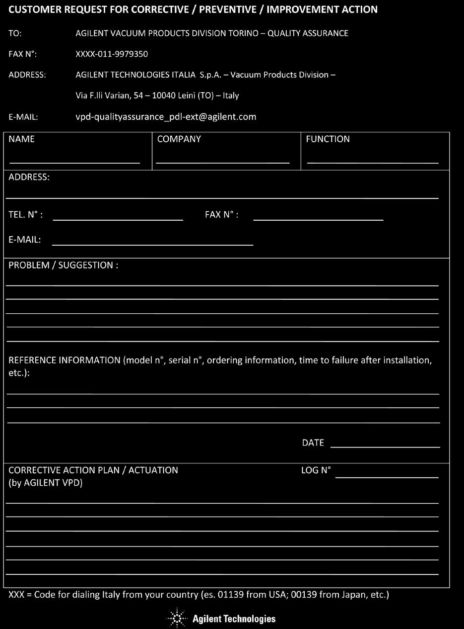
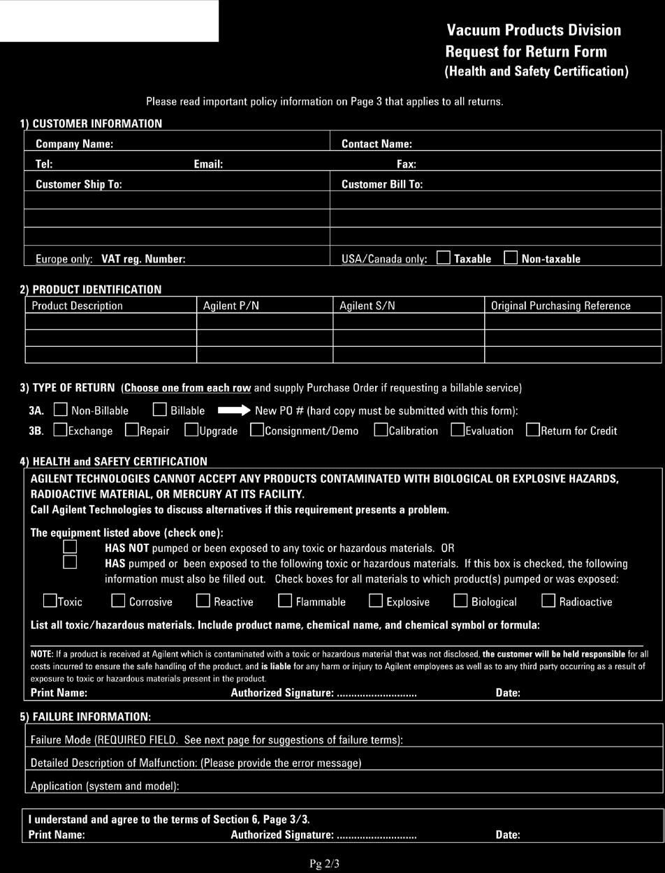
13 Maintenance The TwisTorr 304 FS does not require any maintenance. Any work must be carried out by authorized personnel. WARNING! Before carrying out any work on the system, disconnect it from the mains, vent the pump by opening the appropriate valve, wait until the rotor has stopped turning and wait until the surface temperature of the pump falls below 50 C. In the case of breakdown, contact your local Agilent service center or Agilent advanced exchange service" who can supply a reconditioned system to replace that broken down. NOTE Before returning the pump to the constructor for repairs, or advanced exchange service, the "Request for Return" sheet attached to this instruction manual must be filled-in and sent to the local sales office. A copy of the sheet must be inserted in the system package before shipping. If a system is to be scrapped, it must be disposed of in accordance with the specific national standards.
14 Disposal Meaning of the "WEEE" logo found in labels The following symbol is applied in accordance with the EC WEEE (Waste Electrical and Electronic Equipment) Directive. This symbol (valid only in countries of the European Community) indicates that the product it applies to must NOT be disposed of together with ordinary domestic or industrial waste but must be sent to a differentiated waste collection system. The end user is therefore invited to contact the supplier of the device, whether the Parent Company or a retailer, to initiate the collection and disposal process after checking the contractual terms and conditions of sale.
15 17 Technical Information Description of the TwisTorr 304 FS 241 Pump Description 246 Technical Specification 248 TwisTorr 304 FS Outline 251 Interconnections 270 Earth (Ground) Connection 270 Connection C Electrical 271 Soft Start 272 Inlet screen installation 273 Air Cooling Kit Installation 276 Water Cooling Kit Connection 278 Vent Accessories 281 TwisTorr 304 FS on board controller compatible Vent Valve mod TwisTorr 304 AG Rack Controller Compatible Vent Valve mod Vibration Isolator Installation 285 Purge Valve Installation 286 TwisTorr 304 FS On-board Controller Installation 288 Bottom Mounting 288 Side Mounting 289 Original Instructions
16 Connection of the High Vacuum Flange 290 Installation of ISO-K Flange 291 Installation of ConFlat Flange 292 Connection of the Fore-Vacuum Pump 294 Pump Used with Corrosive Gases 295 Pump Used in Presence of Magnetic Fields 297 Accessories and Spare Parts 298
17 Description of the TwisTorr 304 FS The TwisTorr 304 FS pump is available in various models that differ in the high vacuum flange. The TwisTorr 304 FS pump models are: Model X with ISO 100 high vacuum flange with water cooling; Model X with ConFlat 6 external diameter high vacuum flange with water cooling; Model X with ISO160 high vacuum flange with water cooling; Model X with ConFlat 8 external diameter high vacuum flange with water cooling; Model X with ISO 100 high vacuum flange without water cooling; Model X with ConFlat 6 external diameter high vacuum flange without water cooling; Model X with ISO160 high vacuum flange without water cooling; Model X with ConFlat 8 high vacuum flange without water cooling; Model X (Split Flow) with ISO 100 high vacuum flange and KF40 side port flange with water cooling; The following figures shows the 9 models.

18 Figure 4 Model X Figure 5 Model X


19 Figure 6 Model X Figure 7 Model X

20 Figure 8 Model X Figure 9 Model X

21 Figure 10 Model X Figure 11 Model X
22 Figure 12 Model X Pump Description The TwisTorr 304 pump consists of a high frequency motor driving a turbine fitted with 8 bladed stages and 3 TwisTorr drag stages. The turbine rotates in an anticlockwise direction when viewed from the high vacuum flange end. The turbine is made of high-strength aluminium alloy, machined from a single block. The TwisTorr stages are in the form of three disks. The turbine rotor is supported by permanently lubricated high precision ceramic ball bearings in-stalled on the forevacuum side of the pump. The static blades of the stator are made of stainless steel. These are supported and accurately positioned by spacer rings. The TwisTorr stators are in the form of selfpositioning machined disks. On each disk there are parallel spiral pumping channels designed to pump in centrifugal direction on one side and in centripetal direction on the other side. These are made of aluminium alloy.
23 During normal operation, the motor is fed with a voltage of 54 Vac three-phase at 1010 Hz. To reduce losses during start-up to a minimum, the frequency increases according to a ramp with a higher initial voltage/frequency ratio. WARNING! The pump must always be cooled before starting using it. Running the pump without cooling it could damage inside components. The pump can be water cooled or air cooled: in the first case the customer can use the dedicated channels on the pump body, in the second case an external optional fan is available (model X ). A thermistor sensor is mounted near the upper bearing to prevent the pump from overheating. If the thermistor reading exceeds 60 C the pump fails and stops with Error Code = 2. If the thermistor reading is below 0 C, the pump fails and stops with Error Code = 1 (see Controller Manual), The pump can operate in any position and can be supported on the high vacuum flange. The connection of the forevacuum on the side of the pump is a KF 16 NW flange (KF25 optional).
24 Technical Specification Max gas throughput: o water cooling (water temperature=25 C; backing pump 5 m 3 /h) o air cooling (ambient temperature 25 C; backing pump 5 m 3 /h) Tab. 3 Technical Specification Pumping speed N2 He H2 Ar Max gas throughput at full rotational speed (with recommended forepump) N2 Ar Compression ratio N2 He H2 Ar Base pressure with recommended forepump ISO 100 / CF l/s 255 l/s 220 l/s 250 l/s Air cooling 170 sccm 110 sccm ISO 160 / CF l/s 255 l/s 220 l/s 250 l/s Water cooling 170 sccm 110 sccm > > > < 1 x mbar (< 1 x Torr) (According to standard DIN , the base pressure is that measured in a leak-free test dome, 48 hours after the completion of test dome bake-out, with a Turbopump fitted with a ConFlat flange and using the recommended prevacuum pump) Inlet flange CFF 8" O.D. ISO 160 CFF 6 O.D. ISO 100 Foreline flange KF16 NW (KF25 optional) Rotational speed rpm (1010 Hz driving frequency) Start-up time < 3 minutes Recommended forepump mechanical: Agilent DS 102 mechanical: Agilent DS 302 dry pump: Agilent SH 110 Operating position Any
25 Operating ambient temperature +5 C to +35 C Relative humidity of air Bakeout temperature Lubricant Cooling requirements Coolant water Noise Pressure level Pwr supply (mains): Max input pwr: Stand-by pwr: Max oper. power: Installation category 0 90 % (not condensing) 80 C at inlet flange max. Permanent lubrication Natural convection (only with no gas load) Forced air (5-35 C ambient temperature) Water (mandatory if ambient temperature > 35 C) Minimum flow: 50 l/h (0.89 GPM) Temperature: +15 C to +30 C Pressure: 3 to 5 bar (45 to 75 psi) < 50 db(a) at 1 meter 300 VA 10 W 150 W with water or air cooling II Pollution degree 2 Storage temperature -40 C to +70 C Max altitude 3000 m Weight kg (lbs): Pump ISO kg (12.3) Pump CFF kg (16.5) Pump ISO kg (12.6) Pump CFF kg (20.9)
26 Tab. 4 Split Flow (X ) Technical Specification Pumping speed * N2 He H2 Ar Compression ratio N2 He H2 Ar Max gas throughput at full rotational speed (with recommended forepump) N2 Ar Main Flange (ISO 100) 220 l/s 215 l/s 215 l/s 210 l/s Total > x x 10 5 > Air cooling/water cooling 170 sccm 110 sccm Side Port (KF40) 5 l/s 6.5 l/s 7 l/s 4 l/s Foreline/Side Port >1 x x x 10 3 >1 x 10 6 * Pumping speed measured with fluximeter.
27 TwisTorr 304 FS Outline The following figures show the TwisTorr 304 FS (dimensions are in mm [inches]). Figure 13 TwisTorr 304 FS ISO 100 (X )
28 Figure 14 TwisTorr 304 FS (X )
29 Figure 15 TwisTorr 304 FS (X )
30 Figure 16 TwisTorr 304 FS (X )
31 Figure 17 TwisTorr 304 FS (X )

32 Figure 18 TwisTorr 304 FS + air cooling kit (X X )
33 Figure 19 TwisTorr 304 FS + air cooling kit (X X )

34 Figure 20 TwisTorr 304 FS + air cooling kit (X X )
35 Figure 21 TwisTorr 304 FS + air cooling kit (X X )
36 Figure 22 pump Graph of Pumping Speed vs. Inlet Pressure for TwisTorr 304 FS

37 Figure 23 Graph of Compression ratio vs. Foreline Pressure for TwisTorr 304 FS pump
38 Figure 24 Graph of Iso Flow Iso Power TwisTorr 304 FS pump: Nitrogen
39 Figure 25 Graph of Iso Flow Iso Power TwisTorr 304 FS pump: Argon
40 Figure 26 Graph of Iso Flow Iso Power TwisTorr 304 FS pump: Helium
41 Figure 27 Graph of Iso Flow TwisTorr 304 FS pump: Hydrogen
42 Figure 28 Split Flow (X ): Graph of Pumping Speed (Main Flange ISO100)
43 Figure 29 Split Flow (X ): Graph of Pumping Speed (Side Port KF4)
: Graph of")
44 Figure 30 Split Flow (X ): Graph of Compression Ratio (Total)
")
45 Figure 31 Split Flow (X ): Graph of Compression Ratio (Foreline/Side port)
 Connection We recommend that you fit a separate earth (ground) conductor to the TwisTorr 304 FS.")
46 Interconnections The following figure shows the TwisTorr 304 FS interconnections. Figure 32 Earth (Ground) Connection We recommend that you fit a separate earth (ground) conductor to the TwisTorr 304 FS. Use a separate insulated green/yellow conductor, and use a M5 x 10 screw and shake proof washer (fitted to the earth hole on the pump) to secure the earth conductor to the pump. The screw must be fixed with a 2 Nm torque. The impedance between the pump-body and the earth connection point must be < 0.1 Ω.
47 Connection C Electrical Figure 33 The turbopump is connected to the controller through an 6-pin connector. Pins B, C and D are the 3-phase supply to the motor, pins A and F are connected to the temperature sensor (NTC type, 30 KΩ resistance at 25 C) and pin E is connected to the pump ground. If the temperature sensor is disconnected, the pump will not start. To prevent damage to the pump when the temperature exceeds 60 C, the sensor automatically cuts out the power supply.
48 Soft Start Soft Start mode is provided to start the pump after a protracted stop of the TwisTorr 304 FS. This allows a better grease distribution in the bearings. The Soft Start mode is disabled by default. To enable the Soft Start mode it must be activated by the suitable software or Remote I/O command (see Controller Manual). Soft Start frequency steps are as follow: 300 Hz, 400 Hz, 800 Hz, 900 Hz. For more details see Controller Manual.
49 Inlet screen installation Figure 34 Model and Figure 35 Model X and X The inlet screens mod. X (ISO 100) X (ISO 160) (CFF 6 )
 Ar N2 He H2 X3500-68000 X3500-68001 20% 18% 7% 5% The inlet screen is fitted in the upper part of")
50 (CFF 8 ) prevent the blades of the pump from being damaged by debris. The inlet screen, however, does reduce the pumping speed as followed: Reduction in pumping speed (%) Ar N2 He H2 X X % 18% 7% 5% The inlet screen is fitted in the upper part of the pump, as shown in the figure. Figure 36 The screen can be mounted on each pump. The screen can be removed as shown in the following figure.
51 Figure 37 The overall flange dimensions with the protection screen fitted on pump do not change as the inlet screen remains integrated into the center-ring.
52 Air Cooling Kit Installation An air cooling kit (X ) is available to improve the TwisTorr 304 FS cooling during operational conditions. Fan specifications: air flow: 147 m 3 /h input voltage: 24 Vdc dimensions: 119 x 119 x 32 mm (4.7 x 4.7 x 1.3 in.) power: 2.6 W Figure 38 The fan bracket is shaped so that it can be mounted close to the pump. When the pump is supplied by the rack C.U., please utilize the special fan extension cable
53 To fix the fan to the TwisTorr 304 FS case execute the following procedure (see the following figure): 1 Fix the fan to the suitable bracket by means of the furnished screws; 2 Fix the bracket to the pump body between the pump and the controller; 3 Connect the fan supply to the P4 connector of the controller. Figure 39
54 Water Cooling Kit Connection Two types of water cooling kits are available to be mounted when the pump is used under heavy load conditions or when air cooling is insufficient. The two model part numbers are: (metallic model), and (plastic model). Figure 40 Model Figure 41 Model
55 CAUTION! The items of the plastic model kit must be assembled as shown in the following figure Figure 42 The assembled kit must be screwed into the suitable holes of the pump body with a recommended closing torque of 5 Nm. The metallic model is assembled as shown in the figure. Figure 43
56 Two 6 mm (1/4") internal diameter rubber or plastic hoses from the water supply must be fitted to the two nozzles. NOTE These hoses must be held on the respective nozzles using hose clips to avoid that the tube(s) gets loose or disconnected during operation. Cooling may be carried out either through an open circuit with eventual discharge of the water, or using a closed circuit cooling system. The water temperature must be between +15 C and +30 C, with an inlet pressure between 3 and 5 bar. This allows a flow higher than 50 l/h. NOTE The water electrical conductance must be 500 µs/cm. When the conductance is higher, in closed water circuit, the use of up to 20 % of Ethyl-Glycole is suggested.
57 Vent Accessories The vent valve and vent device allow to avoid undesired venting of the pump during temporary power failure and enables an automatic vent operation. TwisTorr 304 FS on board controller compatible Vent Valve mod Figure 44 This vent valve waits before opening a minimum time of about 5 sec. This time can be increased up to about 220 min. by means of a setting of the controller software (optional). To install the vent valve, unscrew the threaded plug (see figure below).
58 Figure 45 Then screw the vent valve into the pump and tighten it using a 16 mm hexagonal spanner with a torque of 2.5 Nm. Figure 46
59 CAUTION! Do not overtighten the valve as this may damage the thread on the pump. Then connect the cable from the valve to the suitable connector on the controller. TwisTorr 304 AG Rack Controller Compatible Vent Valve mod Figure 47 For further details refers to the Rack Controller manual. To install the vent valve unscrew and remove the threaded plug (see figure below).

60 Figure 48 Screw the flange mod on the pump, taking care of the oring right position. Assemble the seal ring and lock the vent device in position using the KF klamp. Figure 49
61 Vibration Isolator Installation Four vibration isolators for ISO and CFF inlet flange version pumps are available as accessories. The four model part numbers are the following: model for ISO 100 flange; model for ISO 160 flange; model for CFF 6 flange; model for CFF 8 flange. They typically reduce the vibration transmitted from the TwisTorr 304 FS to the system by a factor of 20. Please refer to the relevant instruction manual.

62 Purge Valve Installation A gas purge valve is available to protect the pump bearings against particulate and corrosive gases that could move into the pump. To install the gas purge valve it is necessary to unscrew the purge port cover as shown in the following figure, Figure 50 and then screw the gas purge valve (with a torque of 2.5 Nm) as shown in the following figure.
63 Figure 51
64 TwisTorr 304 FS On-board Controller Installation The controller can be mounted in two position: bottom mounting (as per the complete system) side mounting. To install the controller execute the following procedures. Bottom Mounting See the following figure. 1 Turn the pump upside-down; 2 Screw the 4 fixing studs (provided with the accessories bag) in the holes on the bottom of pump; 3 Place the controller on the studs aligning the 4 rubber holes on the top of the controller case; 4 Press the controller towards the pump; 5 Turn the pump again; 6 Plug the line cord and connect the pump cable to the pump; 7 Connect the mating connector with the jumper on the interlock signal to start the pump.
65 Figure 52 Mounting 1 Side Mounting NOTE The L-shaped bracket (P/N X ) is available as an option. See the following figure. 1 Screw the 4 fixing studs (provided with the accessories bag) in the holes on the L-shaped bracket; 2 Place the controller on the studs aligning the 4 rubber holes on the top of the controller; 3 Press the controller towards the bracket; 4 Turn the pump upside-down; 5 Place the bracket on the pump bottom; 6 Screw a little bit the three screws M4 in the holes on the pump bottom; 7 Rotate the bracket until the controller is on the chosen position;

66 8 Tighten the screws properly; 9 Turn the pump again; 10 Plug the line cord and connect the pump cable to the pump; 11 Connect the mating connector with the jumper on the interlock signal to start the pump. Figure 53 Mounting 2 Connection of the High Vacuum Flange In the case the rotor is suddenly blocked, the torque arising from the system and the high vacuum flange must be absorbed. Only the components listed in the following can be used to fasten the pump to the high vacuum flange.
67 WARNING! It is mandatory to connect the pump in such a way to withstand the torque specified in the "INSTRUCTION FOR USE" section. Specifically pay attention to clamp design, material of clamps and bolts and bolt fixing torque. WARNING! If the pump is fastened on a vacuum chamber with different flange Agilentts there exists the chance of twisting or tearing-off in case the rotor is suddenly blocked. The combination of different flange types is not allowed in any case. Agilent Vacuum will not accept any liability for all damages resulting from not allowed fastening. Installation of ISO-K Flange For ISO-K flange connections, fix the two flanges with the clamps as shown in the following figure (a protective screen can optionally be used).
68 Figure 54 Use the required number of claw clamps: 4 for ISO 100 flange 4 for ISO 160 flange Tighten the claw clamps with a torque of 22 Nm. Installation of ConFlat Flange For ConFlat flange connections, fix the two flanges with the screws as shown in the following figures (a protective screen can optionally be used).
69 Figure 55 Use the required number of screws: 16 for CFF 6 20 for CFF 8 Attach the units and tighten each screw in turn. Repeat the sequential tightening until the flange faces meet. Tighten the screws with a torque of 20 Nm. For ConFlat flange connections we recommend using Agilent hardware. To facilitate assembly and dismantling, apply Felpro C-100 high temperature lubricant to the screw threads protruding from the flange and between the nuts and flange. Note that, in some cases, the connections can be made only with the bolt in the lower side. CAUTION! Exercise care when tightening nuts and bolts to avoid creating dents in the envelope as this may cause the pump rotor to lock.
70 Connection of the Fore-Vacuum Pump A flange KF 16 NW is available to connect the TwisTorr 304 FS pump to the forevacuum pump. A hose or vacuum approved pipe can be used. If a rigid pipe is used, any vibration generated by the mechanical pump must be eliminated through the use of bellows. NOTE The TwisTorr 304 pump is characterized by its high compression ratio also for oil vapors. When using a mechanical oil-sealed pump, it is advisable to install a suitable trap between the turbopump and the fore-vacuum pump in order to prevent oil back-streaming.
71 Pump Used with Corrosive Gases To prevent damage to the bearings, an inert gas must flow into the pump body around the upper bearing towards the forevacuum line. To supply the inert purge gas (e. g. nitrogen) to the pump through the purge port, connect a gas purge valve between the pressure regulator and the pump. Adjust the pressure regulator in order to read a gas flow rate of 0.1 to 0.8 mbar l/s. CAUTION! To prevent bearing damage, Agilent suggests a minimum purge gas flow rate of 10 sccm (0.17 mbar l/s). This value can be exceeded, according to the process requirements. Please contact Agilent for specific applications. The purge gas throughput with the recommended forepump of 15 m 3 /h (11 CFM) allows to achieve a high vacuum pressure in the 10-8 mbar range. The recommended gas flow maintains a pressure into the pump body higher than the forevacuum pressure. The recommended procedure to vent the system and the pump avoiding the contact between the pump bearings and the corrosive gas is described in the following points: 1 Close the corrosive gas flow into the system. 2 Leaving the Turbo pump and the backing pump running and the purge gas flowing, wait for enough time to evacuate the corrosive gas from the system. 3 Turn off the Turbopump. 4 Open the Turbo vent port slowly until to reach atmospheric pressure in the system. 5 When the Turbo pump and the backing pump are stopped and the system is at atmospheric pressure, for a better bearing protection it is advisable to leave the purge gas flowing into the Turbo pump, with the chamber or the Turbo vent valve opened, to avoid system overpressures. If the vent valve can't be kept opened, the backing pump should be left operating.
72 1 Purge gas line 2. Pressure regulator 3. Gas purge valve 4. Gas purge port 5. Forevacuum pump 6. Turbopump 7. Vent valve Figure 56 Purge layout
73 Pump Used in Presence of Magnetic Fields Magnetic fields induce eddy currents in the rotor of a turbomolecular pump that tend to oppose to its rotation. The result is increased electrical power consumption by the motor, most of which is dissipated in the rotor. Since the rotor is not in contact with the stator the above power can leave the rotor mainly by radiation and hence the rotor may be overheated while static parts of the pump remain cool. This effect is strongly dependant from the intensity, time function and distribution of the magnetic field. In general, therefore, an increase in pump current can be expected. If this increase is lower than 50 % of the current value drawn by the motor in high vacuum operation, no particular problem should be expected. However if the effect is grater, than the case should be carefully reviewed by Agilent's specialist. As a matter of fact, in case of high magnetic fields, also important forces might be generated and applied to the rotor.
74 Accessories and Spare Parts Tab. 5 Accessories and spare parts DESCRIPTION PART NUMBER Mains cable NEMA Plug, 3m long Mains cable European Plug, 3m long Serial cable and Navigator Software Inlet screen, ISO 100 X Inlet screen CFF Inlet screen, ISO 160 X Inlet screen CFF Water cooling kit Plastic water cooling kit Air cooling kit for On-board Controller X Air cooling kit for Rack AG Controller X Fan extension cable Bracket for On-Board Controller side mounting X Vibration isolator, ISO Vibration isolator, CF 6" Vibration isolator, ISO Vibration isolator, CF 8" Vent flange, NW 10 KF / M Vent valve for AG Rack Controller Vent valve for on-board Controller Purge valve 10 SCCM NW16KF M Purge valve 10 SCCM ¼ Swagelok M Purge valve 20 SCCM NW16KF M Purge valve 20 SCCM ¼ Swagelok M Purge valve 10 SCCM ¼ Swagelok ¼ Swagelok Purge valve 20 SCCM ¼ Swagelok ¼ Swagelok Foreline flange KF25 1/4 gas Active Gauges Ask Agilent for details

75

76
77

78
Agilent Turbo-V 750 and Turbo-V 850 TwisTorr. The new molecular-drag Technology
 Agilent Turbo-V 75 and Turbo-V 85 TwisTorr The new molecular-drag Technology The new molecular-drag technology What is TwisTorr 2 Agilent Technologies, presents the new TwisTorr molecular drag technology
UPGRADE PROGRAM. V141 Series Pumps vs Turbo-301 Series Pumps. Technical Memo
 UPGRADE PROGRAM V141 Series Pumps vs Turbo-301 Series Pumps Technical Memo INDEX Outline drawings ISO63 3 Outline drawings CF4-½ 6 Outline drawings ISO100 10 Outline drawings CF6 12 Technical Specification
TURBOMOLECULAR PUMPS ATP SERIES
 TURBOMOLECULAR PUMPS ATP SERIES TURBOMOLECULAR PUMPS ATP SERIES Introduction The ATP conventional turbomolecular pumps have a proven track record of reliability. Rotors made exclusively from carefully
Agilent Turbo-V Pumps
 Agilent Turbo-V 2-3 TwisTorr Technology 4-5 TwisTorr Key Features 6-15 TwisTorr Pump Models 16-17 Turbo-V Features and Benefits 18-19 Turbo-V SEM Features and Benefits 20-23 Typical Applications 24-41
Varian, Inc. Vacuum Technologies. Turbo-V Pumps. Turbo-V Pumps Features and Benefits 2-3. Turbo-V SEM Features and Benefits 4-5
 Varian, Inc. Vacuum Technologies Turbo-V Turbo-V Features and Benefits 2-3 Turbo-V SEM Features and Benefits 4-5 Typical Applications 6-11 Pump Models 12-31 Pump Controllers 32-38 Accessories 40-41 Technical
Varian, Inc. Vacuum Technologies. TPS Turbo Pumping Systems. Features and Benefits 2-3. Mini-TASK AG TPS-compact 6-7
 Varian, Inc. Vacuum Technologies TPS Turbo Pumping Systems Features and Benefits 2-3 Mini-TASK AG81 4-5 TPS-compact 6-7 TPS-mobile and TPS-bench 8-10 TPS Turbo Pumping Systems Features and Benefits The
TriScroll TM 620 Series Dry Scroll Vacuum Pump
 vacuum technologies TriScroll TM 620 Series Dry Scroll Vacuum Pump INSTALLATION AND OPERATION MANUAL Manual No. 699904343 Revision E April 2007 TriScroll 620 Dry Scroll Vacuum Pump TriScroll is a trademark
Agilent TwisTorr FS Turbo Pump Family. New generation turbo pumps with TwisTorr drag technology and Agilent Floating Suspension
 Agilent TwisTorr FS Turbo Pump Family New generation turbo pumps with TwisTorr drag technology and Agilent Floating Suspension A New Category of Turbomolecular Pumps Meet the TwisTorr FS family: compact,
The Agilent Advantage
 AGILENT TURBO PUMPS 2-5 Introduction 6-7 Molecular Drag Technology 8-9 Agilent Floating Suspension 10-11 Turbo Pump Technology 12-13 Turbo Pump Technology for Instrumentation 14-17 Typical Applications
Operating Instructions
 Translation of the original instructions ONF 16 S / ONF 25 S Oil Mist Filter Operating Instructions PD 0057 BEN/C (1301) EN Table of contents Table of contents 1 About this manual...............................................
Turbo-V750 and Turbo-V 850 TwisTorr
 Varian, Inc. Vacuum Technologies Turbo-V750 and Turbo-V 850 TwisTorr The new molecular-drag technology TwisTorr The new molecular-drag technology 2010 Today Varian, now a part of Agilent Technologies,
ISP-500B. Oil-free Scroll Vacuum Pump. Instruction Manual. View our inventory. Record of Pump Information. Serial Number: Purchase date:
 ISP-500B Oil-free Scroll Vacuum Pump Instruction Manual View our inventory Serial Number: Record of Pump Information Purchase date: In Service date: Dealer information: IM-500B 1/3/07 Page 1 of 26 Important
Agilent Turbo-V 750 and Turbo-V 850 TwisTorr. The new molecular-drag Technology
 Agilent Turbo-V 750 and Turbo-V 850 TwisTorr The new molecular-drag Technology The new molecular-drag technology What is TwisTorr 2010 Agilent Technologies, presents the new TwisTorr molecular drag technology
TURBOVAC ix Turbomolecular Pumps 90 l/s l/s
 TURBOVAC ix Turbomolecular Pumps 90 l/s - 450 l/s 175.62.02 Discover new dimensions With TURBOVAC ix, highest functionality meets outstanding performance. Our ix turbomolecular pump range with integrated
Operating and Installation Instructions Diaphragm Vacuum Pumps and Compressors
 Operating and Installation Instructions Diaphragm Vacuum Pumps and Compressors Type range: UN813.3ANI UN813.4ANI UN813.3ANDCB UN813.4ANDCB UN813.5ANI Fig. 1: UN813.3ANI Fig. 2: UN813.4ANI You have selected
THE NEW EXPERIENCE IN TURBOPUMPS
 THE NEW EXPERIENCE IN TURBOPUMPS INNOVATIVE PRODUCTS GLOBAL STRENGTH LOCAL SUPPORT VACUUM EXPERTISE The new experience in Turbopumps Edwards, a world leader in vacuum technology, is proud to present the
Instruction Manual. Compound Molecular Pump EBT70F-20
 Instruction Manual Compound Molecular Pump EBT70F-20 Be sure to read and understand all warnings in this manual before using the product. Keep this manual readily available for reference. EBARA Corporation
Pirani Vacuum Gauges. Digital and Analog Vacuum Gauge Systems. Features and Benefits. HPS Products (800) (303)
 (303)") Pirani Vacuum Gauges Digital and Analog Vacuum Gauge Systems Features and Benefits Ideal vacuum gauge for foreline loadlocks Rugged filament design for high reliability Designed for use in harsh process
Pirani Vacuum Gauges Digital and Analog Vacuum Gauge Systems Features and Benefits Ideal vacuum gauge for foreline loadlocks Rugged filament design for high reliability Designed for use in harsh process
Cat. No. I526-E1-1 USER S MANUAL 3G3IV-PLKEB2 /4. Braking Resistor Units 3G3IV-PCDBR2 B/4 B. Braking Units
 Cat. No. I526-E1-1 USER S MANUAL 3G3IV-PLKEB2 /4 Braking Resistor Units 3G3IV-PCDBR2 B/4 B Braking Units Thank you for choosing an OMRON Braking Resistor Unit and Braking Unit. Proper use and handling
Differential Pressure Transmitter
 Specifications/Instructions Differential Pressure Transmitter General Model PY9000D is a differential pressure transmitter that uses a ceramic cantilever sensor. Deflection of the ceramic cantilever caused
2-PHASE STEPPING MOTOR DRIVER FE Z5 DISPENSE
 2-PHASE STEPPING MOTOR DRIVER FE Z5 DISPENSE For Diaphragm Dosing Pumps FEM 1.02_.55 / FEM 1.09_.55 Controller board package, without pump: ID 160536 Operating and Installation Manual It is important to
HANGKAI GROUP HOYMILES MICRO-INVERTER MI-250
 HANGKAI GROUP HOYMILES MICRO-INVERTER MI-250 TECHNICAL MANUAL CONTENTS INTRODUCTION... 3 SAFETY... 4 SYMBOL ILLUSTRATION... 4 INSTALLATION WARNINGS... 6 PREPARE FOR INSTALLING... 7 TRANSPORT AND INSPECT...
HYBRID TURBOMOLECULAR PUMPS ATH SERIES
 HYBRID TURBOMOLECULAR PUMPS ATH SERIES HYBRID TURBOMOLECULAR PUMPS ATH SERIES Introduction Adixen offers the ATH series of hybrid turbomolecular pumps with pumping speeds at 200 and 300 l/s. These models
Scientific vapor pumps
 Scientific vapor pumps Vapor pumps for scientific instruments and R&D applications Diffusion pumps technology and applications - Diffstak -4 Diffstak installation - EO50/60-4 Diffstak combined outfits
High Vacuum Diaphragm-Type Dry Vacuum Pump
 No 腄 26300-2-02-3 High Vacuum Diaphragm-Type Dry Vacuum Pump DTC-120 DTC-120A, 120B, 120C (According to CE) Request to Users Please read this manual thoroughly to ensure safe and effective use of the equipment.
Diaphragm Vacuum Pumps and Compressors
 Operating Instructions Read and observe these Operating Instructions! Diaphragm Vacuum Pumps and Compressors N145 AN.18 N145 AT.18 N145 AV.18 N145.1.2 AN.18 N145.1.2 AT.18 N145.1.2 AV.18 KNF Neuberger
Diaphragm Vacuum Pumps and Compressors
 Operating Instructions Read and observe these Operating Instructions! Diaphragm Vacuum Pumps and Compressors N022 AN.18 N022 AT.18 N022 AV.18 N026.1.2 AN.18 N026.1.2 AT.18 N026.1.2 AV.18 N026.3 AN.18 N026.3
C09. Turbomolecular Pumps l x s -1. vacuum
 179.01.01 Excerpt from the Product Section Edition May 2005 Turbomolecular Pumps 35-3200 l x s -1 vacuum Turbomolecular Pumps Contents General General...............................................03 Applications...........................................12
Vacuum Circuit-Breakers, Type HVX kv, of cassette design, cassette with motor drive
 Vacuum Circuit-Breakers, Type HVX 12 24 kv, of cassette design, cassette with motor drive Operating Instructions No. 531 321, Edition 09/00 Table of Contents 1 General 4 1.1 Operating Conditions 4 2 Design,
Control Gate Valve with stepper motor actuator
 Control Gate Valve with stepper motor actuator This manual is valid for the valve ordering numbers: 64036-.E52 and 64040-.E52 The respective product identification is given on each valve in the following
Swing Piston Compressors and Vacuum Pumps
 Swing Piston Compressors and Vacuum Pumps NPK 018 AC Pressure NPK 018 DC Pressure NPK 018 AC Vacuum NPK 018 DC Vacuum Operating and Installation Instructions Read and observe these Operating and Installation
next TURBOMOLECULAR PUMPS
 edwardsvacuum.com next TURBOMOLECULAR PUMPS THE PARTNER OF CHOICE Edwards is a world leader in the design, technology and manufacture of vacuum pumps with over 95 years history and more than 75 years manufacturing
MICRO-INVERTER OMNIKSOL M-300
 MICRO-INVERTER OMNIKSOL M-300 TECHNICAL MANUAL CONTENTS INTRODUCTION... 3 SAFETY... 4 SYMBOL ILLUSTRATION... 4 INSTALLATION WARNINGS... 6 PREPARE FOR INSTALLING... 7 TRANSPORT AND INSPECT... 7 CHECK INSTALLATION
Instruction Manual (B)
") MT-50E-0-A Instruction Manual (B) STP Series Turbomolecular Pumps STP-F03 Series Pump Specific Information Model name STP-F03 series Voltage 00-40 Va.c. STP pump consists of the three-volumed Instruction
MT-50E-0-A Instruction Manual (B) STP Series Turbomolecular Pumps STP-F03 Series Pump Specific Information Model name STP-F03 series Voltage 00-40 Va.c. STP pump consists of the three-volumed Instruction
AGILENT ROTARY VANE PUMPS
 AGILENT 2-3 Features and Benefits 4- Typical Applications 6-9 Pump Models 20 Accessories 2 HS Series Features and Benefits 22-2 HS Series Pump Models 26-27 MS 40+ Pump Features and Benefits 28-29 MS 40+
AGILENT ROTARY VANE PUMPS
 AGILENT ROTARY VANE PUMPS 2-3 Features and Benefits 4-5 Typical Applications 6-9 Pump Models 20 Accessories 2 HS Series Pumps Features and Benefits 22-25 HS Series Pump Models 26-27 MS 40+ Pump Features
Operators Manual. Recirculating Chiller /06/08
 Operators Manual Recirculating Chiller 110-197 11/06/08 Table of Contents Section 1. General Information 1.1 Warranty 1.2 Unpacking 1.3 Package Contents 1.4 Description of the Recirculating Chiller 1.5
English. Instruction and operation manual S 212. Dew point sensor
 English Instruction and operation manual S 212 Dew point sensor Dear Customer, thank you for choosing our product. The operating instructions must be read in full and carefully observed before starting
Diaphragm Vacuum Pump
 Diaphragm Vacuum Pump with Diaphragm Stabilization System Operating Instructions Read and observe these Operating Instructions! N 920 AP.18 N 920 AP.29.18 N 920 KT.29.18 KNF Neuberger GmbH Alter Weg 3
Swing Piston Compressors and Vacuum Pumps
 Swing Piston Compressors and Vacuum Pumps NPK 050 NPK 0100 Operating and Installation Instructions Read and observe these Operating and Installation Instructions! KNF Neuberger GmbH Alter Weg 3 D-79112
TURBOVAC i Turbomolecular Pumps 90 l/s l/s
 TURBOVAC i Turbomolecular Pumps 90 l/s - 450 l/s 175.61.02 A giant leap in vacuum performance! It has never been so easy to improve your processes until now. TURBOVAC 90-450 i will allow you to optimize
Varian, Inc. Vacuum Technologies. Rotary Vane Pumps. Features and Benefits 2-3. Typical Applications 4-5. Pump Models 6-19.
 Varian, Inc. Vacuum Technologies Rotary Vane Pumps Features and Benefits 2-3 Typical Applications 4-5 Pump Models 6-19 Accessories 20 Frequency Inverter Technology 21 HS Series Pumps 22-25 MS40+ Features
Contents. Overview. Safety Instructions. Before Installation. Installation. Operation. Maintenance. Replacement Parts. System Specifications 8 01
 PrintPRO Universal Contents Overview 1 01 02 03 Overview of your extraction system (front) Overview of your extraction system (back) Overview of the Control Panel Safety Instructions 2 01 Important safety
Instruction in the text
 Read and follow all instructions in this manual. Inform yourself regarding: Hazards which can be caused by the pump; Hazards which can be caused by your system. Hazards which can be caused by the media
WATERFLUX 3070 Quick Start
 WATERFLUX 3070 Quick Start Battery powered electromagnetic water meter Electronic Revision ER 4.3.0_ up to ER 4.3.4_ (SW.REV 4.2.2_ up to 4.2.5_) KROHNE CONTENTS WATERFLUX 3070 1 Safety instructions 4
Mod: KLD6-12/35XLAS-N
 12/2011 Mod: KLD6-12/35XLAS-N Production code: 1914070 INSTRUCTION MANUAL LOGIC LINE PLUS HOOD Reseller Stamp for Warranty Dear customer, Above all, thank you for choosing our product and we would like
Instruction Manual. Description Electrical Supply Item Number
 A702-11-880 Issue F Instruction Manual Drystar GV80 Dry Vacuum Pumps Description Electrical Supply Item Number GV80 Dry Vacuum Pump 220-240/380/400/415 V, 50 Hz A702-12-916 GV80 Dry Vacuum Pump 230/460
EVS RP6020. Instruction Manual
 Instruction Manual TDK Lambda BEFORE USING THE PRODUCT Be sure to read this instruction manual thoroughly before using this product. Pay attention to all cautions and warnings before using this product.
AGILENT TWISTORR FS TURBO PUMPS
 The new generation Turbo Pumps with Agilent Floating Suspension AGILENT TWISTORR FS TURBO PUMPS AGILENT QUALITY ASSURED NEW TwisTorr 304 FS TwisTorr 84 FS Agilent TwisTorr FS Turbo Pumps Agilent Quality
Pump Manual. Model Numbers: SP240VDFS57LPM SP240VDFS80LPM. Product Names: Digital Refueling Station - 57 L/min Digital Refueling Station - 80 L/min
 Pump Manual Model Numbers: SP240VDFS57LPM SP240VDFS80LPM Product Names: Digital Refueling Station - 57 L/min Digital Refueling Station - 80 L/min Copyright: Scintex Fuel Depot 2012[Type text] Page 1 WARNING:
TURBOVAC i Multi Inlet Line Turbomolecular pumps
 TURBOVAC 350-400 i Multi Inlet Line Turbomolecular pumps A giant leap in vacuum performance: one-of-a-kind vacuum techno logy Precision is key when it comes to analytical instruments that is why we invented
HiPace 60 P with TC 110, DN 63 ISO-K
 HiPace 60 P with TC 110, DN 63 ISO-K HiPace 60 P with TC 110, DN 63 ISO-K Small yet powerful turbo molecular pump without Holweck-stage with a pumping speed of up to 64 l/s for N 2 Integrated TC 110 drive
RP Instruction Manual
 Instruction Manual TDK Lambda BEFORE USING THE PRODUCT Be sure to read this instruction manual thoroughly before using this product. Pay attention to all cautions and warnings before using this product.
Instruction Manual. Table of Contents. Powder Clutch, Brake MODEL ZKB-AN,BN Powder Clutch ZKB-YN,XN Powder Brake
 ZJ-267A Powder Clutch, Brake MODEL ZKB-AN,BN Powder Clutch ZKB-YN,XN Powder Brake Instruction Manual Table of Contents Cautions on Safety - - - - - - - - - - - - - - - - - 1 1. Cautions before use - -
Digital Flow Switch (Sensor Part) Operation Manual
 Operation Manual") Digital Flow Switch (Sensor Part) Operation Manual For Air PF2A 50/5 Series PF2A 5/ 52/ 55 Series For Water PF2W /520/50 Series PF2W 5 Series For Water (High Temperature Fluid Type) PF2W T/520T/50T Series
Digital Flow Switch (Sensor Part) Operation Manual For Air PF2A 50/5 Series PF2A 5/ 52/ 55 Series For Water PF2W /520/50 Series PF2W 5 Series For Water (High Temperature Fluid Type) PF2W T/520T/50T Series
D Issue J. Instruction Manual. Active Inverted Magnetron Gauge. Original instructions
 Instruction Manual D146-41-880 Issue J Active Inverted Magnetron Gauge Description AIM-S-NW25 AIM-SL-NW25 AIM-X-NW25 AIM-XL-NW25 Item Number D146-41-000 D146-44-000 D146-42-000 D146-45-000 Original instructions
HiPace 80 for TCP 350, DN 63 ISO-K
 HiPace 80 for TCP 350, DN 63 ISO-K HiPace 80 for TCP 350, DN 63 ISO-K Small yet powerful turbopump with a pumping speed of up to 67 l/s for N 2 External TCP 350 drive electronics For installation in any
TIDALFLUX 2300 F Quick Start
 Quick Start Electromagnetic flow sensor for partially filled pipes The documentation is only complete when used in combination with the relevant documentation for the signal converter. KROHNE CONTENTS
Installation and Operational Instructions for ROBATIC -clutch Type and Type Sizes 3 9
 Please read the Operational Instructions carefully and follow them accordingly! Ignoring these Instructions may lead to malfunctions or to clutch failure, resulting in damage to other parts. Contents:
Arm - TX series 40 family
 Arm - TX series 40 family Characteristics Stäubli Faverges 2005 D18327304A - 02/2005 The specifications contained in the present document can be modified without notice. Although all necessary precautions
INTRODUCTION WARNING SIGNS AND THEIR MEANINGS
 INTRODUCTION FMI-series frameless motors by Rozum Robotics are designed to provide motion as part of a motion system. Available in a range of sizes (stator dia. 41, 51, 75 mm), FMI motors are suitable
Micro Motion F-Series Coriolis Flow and Density Sensors. Installation Manual , Rev CC December 2010
 Micro Motion F-Series Coriolis Flow and Density Sensors Installation Manual 20002298, Rev CC December 2010 Safety and approval information This Micro Motion product complies with all applicable European
SERVO MOTORS BRUSHLESS SERVO MOTORS OPERATING INSTRUCTIONS 2016
 SERVO MOTORS BRUSHLESS SERVO MOTORS OPERATING INSTRUCTIONS 2016 3009/16 en Ed.02.2016 Read these Operating Instructions before performing any transportation, installation, commissioning, maintenance or
Dual Stage Rotary Vane Pumps
 VACUTEC P.O.BOX 48488 Roosevelt Park 2129 South Africa Tel: +27 (0) 11 475 1823 Fax: +27 (0) 11 475 1819 Email: sales@vacutec.co.za Dual Stage Rotary Vane Pumps Features and Benefits 16-17 Typical Applications
Compact System NRGS 11-2 NRGS Original Installation Instructions English
 Compact System NRGS 11-2 NRGS 16-2 EN English Original Installation Instructions 810366-05 1 Contents Important Notes Page Usage for the intended purpose...4 Safety note...4 LV (Low Voltage) Directive
Operating and Installation Instructions Diaphragm Gas Sampling Pumps
 Operating and Installation Instructions Diaphragm Gas Sampling Pumps UN026FT.16I UN726FTI UN726FT.29I KNF Neuberger, Inc 2 Black Forest Rd Trenton, NJ 08691-1810 Phone: 609-890-8600 Fax: 609-890-8323 www.knf.com/usa.htm
Installation, Operating & Maintenance Instructions. All-metal gate valve with compact or extended pneumatic actuator
 Installation, Operating & Maintenance Instructions All-metal gate valve with compact or extended pneumatic actuator Series 48 DN 16 320 mm (I.D. ⅝" 12") This manual is valid for the following product ordering
Series 275 Mini-Convectron Vacuum Gauge Module with Nonlinear Analog Outputs and Process Control Relays Instruction Manual
 Series 275 Mini-Convectron Vacuum Gauge Module with Nonlinear Analog Outputs and Process Control Relays Instruction Manual Instruction Manual Instruction manual part number 275512 Revision E- July 2017
NEOTECHA NTB-NTC BALL VALVES INSTALLATION AND MAINTENANCE INSTRUCTIONS
 Before installation these instructions must be fully read and understood 2 SAFETY Please also read through these notes carefully. 2.1 General potential danger due to: a. Failure to observe the instructions
Switching DC Power Supply
 99 Washington Street Melrose, MA 02176 Phone 781-665-1400 Toll Free 1-800-517-8431 Visit us at www.testequipmentdepot.com Model 1693, 1694 Switching DC Power Supply INSTRUCTION MANUAL 1 Safety Summary
Operating Manual. Follow all safety precautions!
 Operating Manual This manual contains important information necessary for the safe and efficient operation of the PhotoFluor LM-75 light source. Please read the manual in its entirety and heed all safety
RS-3 PRO RS-1007 PRO. CAT IV Analog Clamp meter Series. Users Manual. For detailed specifications and ordering info go to
 RS-3 PRO RS-1007 PRO CAT IV Analog Clamp meter Series Users Manual For detailed specifications and ordering info go to www.testequipmentdepot.com RS-3 PRO RS-1007 PRO CAT IV Analog Clampmeter Series English
Below, you can see the warning symbols used throughout the manual and their meaning.
 FMI60201 Frameless motors INTRODUCTION FMI-series frameless motors by Rozum Robotics are designed to provide motion as part of a motion system. Available in a range of sizes (dia. 40, 50, 60, 75 mm), FMI
Installation and Operational Instructions for ROBATIC -clutch Types _.0 and _.0 Sizes 3 7
 Please read these Installation and Operational Instructions carefully and follow them accordingly! Ignoring these Instructions may lead to malfunction or to clutch failure, resulting in damage to other
1. SPECIFICATION. Altitude of motor installation. Information: Resistance and temperature specifications of the PTC thermistor / posistor/.
 1. SPECIFICATION 5 GENERAL INFORMATION Motors with parameters according to the data sheet comply with the requirements of the IEC 60034-1 standard, and IEC 60034-30 class efficiency IE2 Motor versions:
System 3 ZB1PS Device Chassis. Operator s Manual
 System 3 ZB1PS Device Chassis Operator s Manual System 3 ZB1PS Operator's Manual Copyright 2007 Tucker-Davis Technologies, Inc. (TDT). All rights reserved. No part of this manual may be reproduced or transmitted
AIR FILTER MODEL NO: AF1000 OPERATION & MAINTENANCE INSTRUCTIONS PART NO:
 AIR FILTER MODEL NO: AF1000 PART NO: 6471160 OPERATION & MAINTENANCE INSTRUCTIONS 1208 INTRODUCTION Thank you for purchasing this Clarke Air Filter. Before you try to use this product, read this manual
Dycon D1532SM. EN50131/PD6662 Grade 3, 12V 2A Power Supply. Technical Description Installation and Operating Manual DYCON POWER SOLUTIONS LTD
 Dycon D1532SM EN50131/PD6662 Grade 3, 12V 2A Power Supply Technical Description Installation and Operating Manual DYCON POWER SOLUTIONS LTD Tel: +44 (0)1443 471 900 Unit A Cwm Cynon Business Park Mountain
These installation and maintenance instructions must be read in full and completely understood before the installation!
 These installation and maintenance instructions must be read in full and completely understood before the installation! 1. General information on the installation and maintenance instructions These instructions
GateKeeper Aluminum Gate Valves
 GateKeeper Aluminum Gate Valves 250 mm Air-Operated 100 mm Air-Operated 63 mm Air-Operated The GateKeeper Series Aluminum Gate Valves are economical, reliable vacuum shut-off devices designed and manufactured
Operating manual Separator
 Operating manual Separator Sheet no. AS/4.1.141.1.1 issue 20.08.2014 Contents Section Title Page 0 Introduction... 1 1 Intended use......1 2 Marking of the fitting... 1 3 Safety instructions... 2 4 Transport
RT Series Step Down Transformer for RT Series UPS 6-10kVA UL Input Vac Output Vac User Guide
 RT Series Step Down Transformer for RT Series UPS 6-10kVA UL Input 208-240 Vac Output 208-120 Vac User Guide UNLESS SPECIFICALLY AGREED TO IN WRITING, SELLER (A) MAKES NO WARRANTY AS TO THE ACCURACY, SUFFICIENCY
Turbomolecular Pumps TURBOVAC SL The New Premium Line
 Turbomolecular Pumps TURBOVAC SL The New Premium Line. 175.60.02 High Vacuum. Experience, Performance, Innovation. Oerlikon Leybold Vacuum has been a world leader in vacuum technology for over 150 years,
Installation, Operating & Maintenance Instructions. HV gate valve with pneumatic actuator. Series 110 DN mm (I. D.
 Installation, Operating & Maintenance Instructions HV gate valve with pneumatic actuator Series 110 DN 250 320 mm (I. D. 10" 12") This manual is valid for the following product ordering numbers: 11048-.
190M. Medical ScopeMeter. Safety Information
 190M Medical ScopeMeter PN 4202934 June 2012, Rev. 1 2012 Fluke Corporation. All rights reserved. Printed in Romania. All product names are trademarks of their respective companies. WX Warning To prevent
TPH Series. MULTISTAGE CENTRIFUGAL PUMP Instruction Manual WALRUS PUMP CO., LTD. ISO 9001 Certified NSF/ANSI 372
 TPH Series MULTISTAGE CENTRIFUGAL PUMP Instruction Manual NSF/ANSI 372 ISO 9001 Certified WALRUS PUMP CO., LTD. EC Declaration of Conformity Manufacturer: Walrus Pump Co., Ltd. Address: No.8314, Dapiantou,
Turbocharger / VTR..0, VTR..1 Original assembly instructions English
 Assembly Instructions Turbocharger / VTR..0, VTR..1 Original assembly instructions English This document is valid for the VTR..0/..1 series: VTR160, VTR200, VTR250, VTR320, VTR400 VTR161, VTR201, VTR251,
Read and understand this manual for safely usage.
 TS02-0180 INSTRUCTION MANUAL FOR AIR BUBBLER SYSTEM LEVEL MEASUREMENT MODEL:LA100 MODEL:LA110 MODEL:LA1000 Read and understand this manual for safely usage. This manual describes the product of standard
HiPace 300 Plus with TC 110, DN 100 ISO-F
 HiPace 300 Plus with TC 110, DN 100 ISO-F HiPace 300 Plus with TC 110, DN 100 ISO-F Compact yet powerful turbopump with a pumping speed of up to 260 l/s for N 2 Integrated TC 110 drive electronics Low
Type Operating Instructions. Bedienungsanleitung Manuel d utilisation
 Globe control valve, pneumatically operated Actuator sizes 40 mm - 125 mm, Nominal diameter DN10-65 Kolbengesteuertes Geradsitzventil Antriebsgrößen 40 mm - 125 mm, Nennweiten DN10-65 Vanne à siège droit
HV-Angle Valve (Series 264) HV-InlineValve (Series 265) with electromagnetic actuator single acting with closing spring (NC)
 HV-InlineValve (Series 265) with electromagnetic actuator single acting with closing spring (NC)") HV-Angle Valve (Series 264) HV-InlineValve (Series 265) with electromagnetic actuator single acting with closing spring (NC) This manual is valid for the valve ordering number(s): 26... 26428 -K A 61 A..
HV-Angle Valve (Series 264) HV-InlineValve (Series 265) with electromagnetic actuator single acting with closing spring (NC) This manual is valid for the valve ordering number(s): 26... 26428 -K A 61 A..
FL 10 DIAPHRAGM PUMP INSTALLATION INSTRUCTIONS. Before operating the pump, please read the Installation Instructions and safety precautions.
 FL 10 INSTALLATION INSTRUCTIONS DIAPHRAGM PUMP FL 10 DC-P FL 10 AC Before operating the pump, please read the Installation Instructions and safety precautions. Installation Instructions FL 10 Table of
Xenon Fiberoptic Lightsource
 Xenon Fiberoptic Lightsource Operating Instructions for ASB-XE-175W Lightsource 2659A Pan American Frw N.E Albuquerque, New Mexico 87107 USA (English) Page 1 of 12 TABLE OF CONTENTS PAGE 1. INTRODUCTION
OPERATIONS MANUAL. Mini Centrifuge Model MCF Certified
 OPERATIONS MANUAL Mini Centrifuge Model MCF-2360 Certified Contents 1. Safety 2 2. Introduction 7 3. Package Contents 7 4. Specifications 8 5. Features 8 6. Parts of the Mini Centrifuge 9 7. Installation
PowerLogic High Density Metering System 4-Meter Enclosure Installation Guide
 PowerLogic High Density Metering System 4-Meter Enclosure Installation Guide 7002-0289-00 Instruction Bulletin HAZARD CATEGORIES AND SPECIAL SYMBOLS Read these instructions carefully and look at the equipment
ACC Series Power Conditioner OPERATION & INSTALLATION MANUAL
 ACC Series Power Conditioner OPERATION & INSTALLATION MANUAL PHASETEC digital power conditioners are designed to safely operate electrical equipment in the harshest power quality environments. With a wide
Installation Guide. Auxiliary Pressure Control Manifold on 6890 GC Accessory G1570A
 Installation Guide Auxiliary Pressure Control Manifold on 6890 GC Accessory G1570A Agilent Technologies 2001 All Rights Reserved. Reproduction, adaptation, or translation without permission is prohibited,
Operating and Installation Instructions Swing Piston Compressors and Vacuum Pumps
 Operating and Installation Instructions Swing Piston Compressors and Vacuum Pumps UNPK04DC Pressure UNPK04DCB Pressure UNPK04DC Vacuum UNPK04DCB Vacuum KNF Neuberger, Inc 2 Black Forest Rd Trenton, NJ
RADEX -N Composite Operating/Assembly instructions
 1 of 14 RADEX -N is a torsionally stiff flexible steel lamina coupling. It is able to compensate for shaft misalignment, for example caused by thermal expansion, etc. note ISO 101. Drawn: 0.05.15 Kb/Wig
Installation, Operating & Maintenance Instructions. UHV gate valve with pneumatic actuator. Series 108 DN mm (I. D. 2½ 8 )
") Installation, Operating & Maintenance Instructions UHV gate valve with pneumatic actuator Series 108 DN 63 200 mm (I. D. 2½ 8 ) This manual is valid for the following product ordering numbers: 108.. -.
Installation, Operating & Maintenance Instructions UHV gate valve with pneumatic actuator Series 108 DN 63 200 mm (I. D. 2½ 8 ) This manual is valid for the following product ordering numbers: 108.. -.