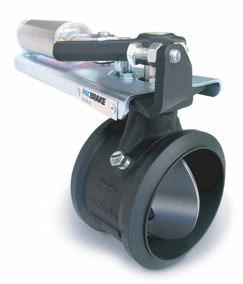
Getting Started. INLINE MOUNT Exhaust Brakes. Thank you and congratulations on your purchase of a Pacbrake Inline Mount exhaust brake kit.
|
|
|
- Vincent Moody
- 5 years ago
- Views:
Transcription
1


2 Getting Started Thank you and congratulations on your purchase of a Pacbrake Inline Mount exhaust brake kit. Before starting, be sure you have attained the proper brake, mounting kit and control group for your vehicle. Below is a sample of all the parts needed for installation. *Some models require back pressure adjustment. For these models a gauge kit is required. PN C Verify the vehicles exhaust pipe size is correct for the adapters supplied. NOTE: The adapters are expanded to slide over the existing exhaust pipe. Pacbrake adapters are available for all standard exhaust pipe sizes. Compare the exhaust pipe OD against the adapter I.D. before cutting the exhaust pipe. 1 With the exhaust brake on the bench, loosely attach the exhaust pipe adapters provided, and make a measurement to determine the length of vehicle exhaust pipe to be removed. The adapters are expanded to slide over the existing exhaust pipe consider this in your measurement 2 Select a location that has suffi cient clearance for installation and servicing of the exhaust brake. This location should be as close to the turbocharger as possible and away from dirt and road spray. Keep in mind that Exhaust Brakes subjected to road spray will shorten the life and require a Remote Cylinder Breather Kit PN# C Transfer the brake/adapter measurement to this location and mark the exhaust pipe. Remove the exhaust pipe and cut the pre-marked section. NOTE: In some cases, the cutting and welding of exhaust systems can be done without removing the pipe sections from the vehicle. INSTALLATION MANUAL - L2031 PG. 2


3 3 Clamp exhaust brake and exhaust system in place and tack weld prior to fi nal welding. Weld the adapters to the sections of pipe, being careful to maintain the proper length and angles that exist. Welding can be done on the outside or the inside of the adapter, but it must be leak free. NOTE: Clamped joints that exist between the brake and the engine must also be welded at this time to ensure the joint cannot separate or leak under pressure. 4 If removed, reinstall the front section of pipe on the engine. Torque turbo clamp to engine manufacturers specifi cation. Center brake and tighten clamp on the exhaust brake pressure side. Install the rear section of pipe and loosely clamp. Check alignment of all sections and joints and torque V clamps to 15 FT.LBS. 5 Select a location to mount the 12V compressor assembly. Mounting can be in any position. The location should be free of heat and contamination and must provide the compressor a good electrical ground by attaching the compressor grounding wire to a good ground source. INSTALLATION MANUAL - L2031 PG. 3

4 6 Prior to mounting the compressor, attach the air fi lter to the intake port and fi rmly tighten by hand. Attach the rubber mounting feet to the compressor mounting brackets using the grommets and grommet sleeves provided. These will isolate the compressor from vibration NOTE: A remote breather kit for compressor intake air must be used if dust or road spray is present near the air intake filter. Pacbrake P/N C11620 is available and must be ordered separately. (shown in diagram) 7 Route the Tefl on air hose from the compressor assembly to the fi tting on the air cyclinder. Cut the hose and make the connection, being careful that the hose is secured away from any heat that could damage it. INSTALLATION MANUAL - L2031 PG. 4
5 Wiring Schematic Index * Ford Econoline Vans equipped with Powerstroke, see wiring schematic on page 6 * Pre-1998 Ford Econoline Vans Equipped with Powerstroke, see wiring schematic on page 9 * Navistar vehicles equipped with 444E, see wiring schematic on Page 13 * Dodge 24 Valve Electronic equipped with Cummins 5.9/ISB, see wiring schematic on page 14 * Pre 1999 Dodge 12 Valve Mechanical equipped with Cummins 5.9, see wiring schematic on page 16 Application Guide Engine Max. Exhaust Brake Econoline or Ford Powerstroke 32 PSI 3400 C20366 Dodge Cummins 5.9L 35 PSI 3100 *C10300 Dodge Cummins 5.9L 60 PSI 3100 *C20369 (with heavy duty valve springs) Dodge Cummins 24 valve 60 PSI 3100 *C10300 International 444E 32PSI 3400 *C20366 *C10300 model is an adjustable brake and must be set during a road test using a backpressure gauge. Due to upgrades and variations between engines (i.e: different turbo chargers) it is not possible for Pacbrake to provide a preset brake to cover all possibilities. Testing Exhaust Brake Back Pressure Prepare for road test check or set exhaust brake back pressure. Pacbrake test gauge kit PT# C10600, can be purchased through the Pacbrake distribution system. This kit contains all the necessary parts to perform back pressure tests. The gauge used must be a dampened (liquid fi lled) type to accurately read this pressure. 1. Remove the 1/8 NPT plug located in the exhaust brake body and install fi tting #3. Install the steel tube #4 into the fi tting installed in the exhaust brake. Instert fi ttings #5 and #6 into the neoprene hose, moistening the fi ttings and fi rmly pushing the hose onto the barbed end. Install one end of the hose to the steel tube and the other to the gauge. Tighten all fi ttings securely. Route neoprene hose into cab. Note: This test must be performed to ensure engine manufactures back pressure specifications are not exceeded - check the application guide for the correct maximum allowable PSI setting at governed speed. 2. Warm the engine to normal operating temperature. 3. Road test the vehicle by providing long durations of maximum RPM with the exhaust brake applied. This is best achieved with weight in the vehicle and a downhill grade. 4..Read and record the pressure achieved on the gauge at the governed engine speed. Pacbrake inline models have an adjustable stop bolt to adjust exhaust back pressure, This is done by the stop screw which limits the activating arm travel, thus reducing back pressure. INSTALLATION MANUAL - L2031 PG. 5
6 C10600 Test Gauge Kit must be ordered separately 1 Illus.No. Part No. Description Qty 1 C10650 Gauge 1 2 C10800 Hose 1 3 C10678 Fitting 1 4 C10677 Steel Tube 1 5 C10676 Fitting 1 6 C10775 Fitting INSTALLATION MANUAL - L2031 PG. 6
7 EXHAUST BRAKE WIRING SCHEMATIC Ford Trucks and Econoline Vans Equipped With Powerstroke NOTE: SHADED AREA APPLIES TO CRUISE CONTROL VEHICLES To Ford PCM Ford Brake Pressure switch Blk./Yel. Blue Blk./Yel. Blue Cruise Relay Black Dash switch OFF Ground Air Intake Filter a 86 Relay 20 Amp Fuse Connect to positive battery terminal Firewall To IVS Yellow a Black Ground Black 15 Amp Fuse 12V+ Ignition Switched To Brake THROTTLE RELAY INSTALLATION At the throttle pedal, locate the I.V.S. (Idle Validation Switch). NOTE: The IVS connection is critical and must be correct. We recommend using a 12 volt test light to verify the correct wire BEFORE installing the T tap. Most common for vehicles built after 10/2000 is a red wire with a green stripe 2nd from the top of the connector, however because of possible production changes, using a test light is the only way to be sure. With the ignition on, probe this wire with the test light fi rst as it should be 12 volt positive with the accelerator pedal to the fl oor. Release the pedal and the light should go off. If this is correct connect this wire as explained below, if not, probe the remaining wires until you locate the one which has 12 volts positive with the accelerator pedal depressed and no current with the pedal released. With the correct wire selected, use the blue electrical T tap supplied and tap into this wire. Plug the insulated male end of the 12 yellow wire into the T tap. Connect the opposite end of the yellow wire to terminal 86 of the supplied relay. Connect the 12 black wire to terminal 85 of the relay and fi nd a good vehicle ground for the eye terminal on the opposite end. Connect the two red harness wires to terminals 30 and 87A and then secure the relay to existing wiring (in this location) with the tystraps provided. INSTALLATION MANUAL - L2031 PG. 7


8 Ford Trucks and Econoline Vans with Powerstroke 1 For vehicles WITHOUT cruise control, omit steps 1 & 2. Remove the ground strap bolt on the driver-side of the fi rewall and install the relay receptacle and relay ground wire on this bolt. Install relay into the receptacle. 2 Ford installs a brake pressure applied switch on the front lower side of the master cylinder. Locate the black wire with a yellow stripe. Cut this wire and crimp on the two red terminals provided. Connect these to the mating terminals of the two remaining blue wires coming from the relay harness. Neatly secure all wiring with the plastic ties. Connect the wiring harness to the solenoid and to the cruise relay. 3 Remove the lower instrument panel (see arrow). Drill a 1/2 hole as shown for the dash switch. The dash switch location is a suggestion only. Install the Pacbrake on/off switch. Connect the two wiring harnesses to this switch, observing the correct wire and terminal locations as shown in the wiring schematic. Switch location can vary depending on customer choice or the availability of space. Choose a location which is convenient to the driver. Pacbrake offers a transmission gear lever mounted on/off switch for manual transmission equipped vehicles. 4 Locate a 12 volt ignition power source in the harness directly below the steering column (see arrow). Attach the yellow T-tap connector to this wire which should be 12V+ ignition switched. INSTALLATION MANUAL - L2031 PG. 8
9 EXHAUST BRAKE WIRING SCHEMATIC Pre 1998 Ford Trucks and Econoline Vans Equipped With Powerstroke NOTE: SHADED AREA APPLIES TO CRUISE CONTROL VEHICLES To Ford PCM Ford Brake Pressure switch Blk./Yel. Blue Blk./Yel. Blue Cruise Relay Black Dash switch OFF Ground Air Intake Filter a 86 Relay 20 Amp Fuse Connect to positive battery terminal Firewall Throttle Switch Black 15 Amp Fuse 12V+ Ignition Switched To Brake INSTALLATION MANUAL - L2031 PG. 9


.")

10 Pre 1998 Ford Trucks and Econoline Vans with Powerstroke 1 For vehicles without cruise control, omit steps 1-2. Remove the relay and mount the receptacle of the C11971 harness to the fi rewall, including the green ground wire, with the screw supplied. Replace the relay. Connect both harnesses together using the remaining red wire. 2 Ford installs a Brake Pressure Applied Switch on the TOP of their master cylinder. Open the convoluted conduit leading to this switch and pull out the black with yellow stripe wire. Cut this wire and crimp on the two red terminals supplied. Finally, connect these to the mating terminals of the two remaining blue wires coming from the relay. Replace the engine top cover and neatly secure all wiring with the plastic ties. 3 Drill a 1/2 hole through the fi rewall, above the throttle switch and below the clutch master cylinder or blanking plate (auto trans.). Feed the switch terminal end of the harness through this hole into the cab compartment. 4 The Pacbrake throttle switch assembly mounts on the outside of the existing Ford switch located above the accelerator pedal, as shown in the schematic. Using a #20 Torx driver, remove the screw which attaches the existing switch and install the Pacbrake switch assembly. Align the two small bracket dimples with the depressions in the mounting bracket. Adjust the switch by bending the switch arm to obtain a click each time the throttle returns to idle. The Ford switch will also click at this time. NOTE: Should the locating dimples not be realigned, poor throttle response will result. INSTALLATION MANUAL - L2031 PG. 10
. Attach the blue Ttap connector to this wire which should be 12V+, ignition switched.")
11 Throttle Switch Schematic Pacbrake Throttle Switch Ford Throttle Switch #20 Torx Screw "Locating" Dimples Ford Accelerator Pedal Linkage 5 Locate a 12 volt ignition power source in the harness directly below the steering column (see pointer). Attach the blue Ttap connector to this wire which should be 12V+, ignition switched. Plug the black fused wire into this connector, attach fuse holder in an accessible location and replace panel. Continue the harness to the previously installed throttle switch, and connect the green and black wires to the terminal on the side of the switch and the one on the end adjacent to it. See schematic. Replace panel. Check Operation Start engine and turn Pacbrake on (engine will idle with Pacbrake engaged). Advance the throttle from idle to approximately 1200 RPM and back to idle several times, ensuring that the Pacbrake applies and releases each time. Check for exhaust leaks at all connections. Shut engine down and do a fi nal check of all clamps, fi ttings, wiring and plastic ties. Road test vehicle, and with cruise control activated, turn Pacbrake switch on. With throttle in idle position, cruise control should cancel immediately. NOTE: Whenever the Pacbrake switch is on and throttle at idle, cruise control cannot be engaged. NOTE: Re-torque turbo clamp and exhaust brake clamps after 100 miles (engine should be cold). Retarding Performance: 250 3,400 rpm. Dynamometer the rear wheels (automatic transmission model only). If you have any questions or comments, please don t hesitate to give us call at INSTALLATION MANUAL - L2031 PG. 11
12 NAVPAC EXHAUST BRAKE WIRING SCHEMATIC INTERNATIONAL 444E NAVPAK SYSTEMS For vehicles: (WITHOUT) Allison WT Transmission (WITHOUT) ABS Braking (WITHOUT) On-board air supply Pacbrake On/Off switch Exhaust brake OFF Pacbrake exhaust brake relay Air Intake Filter Amp Fuse A 85 Connect to positive battery terminal 30 87a Relay Pin A 94 GC Connector 377 Pin E 24 GY Ground Pin 15 NavPak ECM Pin 47 Ignition power 10 amp 24A GY 24B GY Pin B Pin A Connector 372 NOTE: Pacbrake wiring kit contains toggle type switch, source Navistar rocker switch part number C1 if desired. The NavPak ECM requires exhaust brake circuit to be enabled by a Navistar Dealer. Relay shown is de-energized. Connector 372 located behind the left cylinder head. Remove protective cap and connect to Pacbrake harness (supplied). 8 Pin connector 377 located behind fuse panel. Information for this schematic was derived from vehicle systems at the date of this printing. Updates or variations by vehicle manufacturers constituting changes will not be the responsibility of Pacbrake. Pacbrake harness supplied in dotted area. Navistar installed wires in circled area. INSTALLATION MANUAL - L2031 PG. 12
13 EXHAUST BRAKE WIRING SCHEMATIC 1999 to 2002 DODGE 24 Valve Electronic Wiring Harness installation Air Intake Filter T-tap terminal 12V ignition-on power source 10 Amp Fuse a 86 Relay 20 Amp Fuse Connect to positive battery terminal Black Ground Relay Black On/Off Switch Ground Pin a 86 Ground Yellow ECU Cummins/Dodge Black Drip Loop 12 Volt output Throttle Signal In a convenient location on the drivers side of the engine compartment, using the self tapping screw provided, mount the Pacbrake 1 relay receptacle with the green ground terminal under the screw head. Install relay. Route the loomed yellow wire through the fi rewall grommet into the cab to be connected to the dash switch later. 2 ECM CONNECTION Disconnect both negative battery cables. Remove the two cap-screws that attach the fuel fi lter head to the intake manifold, this should allow enough clearance to access the 50 pin connector. Locate the 50 pin connector at the ECM shown above. Locate port #20 and remove the sealing plug. Be careful not to push the plug in. Insert the black wire of the Pacbrake harness into pin #20 until it stops, then pull gently to ensure the terminal is locked in place. Using the plastic ties supplied, secure the Pacbrake harness to the Dodge main harness. Be sure to follow Drip Loop in the Dodge harness when securing the Pacbrake harness. Reinstall the fuel fi lter head to the intake manifold. INSTALLATION MANUAL - L2031 PG. 13
14 COMPRESSOR INSTALLATION 3 Select a location to mount the 12 volt compressor assembly. The location should be away from heat sources, contamination and must provide the compressor with a good electrical ground by attaching the compressor grounding wire to a good ground source. Route the compressor power supply to the positive battery terminal and connect, secure wire with tie-straps supplied. NOTE: A remote breather kit for the compressor intake must be used if dust or road spray is present near the air intake filter. Pacbrake part# C11620 is available and must be ordered separately. 4 ON/OFF SWITCH INSTALLATION Switch location can vary depending on customer choice or the availability of space. Choose a location which is convenient to the driver. Pacbrake offers a gear lever mounted switch for manual transmission equipped vehicles. (It is a good idea to consult the operator of the vehicle for their preference.) Most importantly, locate an area which is free from obstruction. Remove dash panel below steering column. Note the panel is double wall construction and the inner wall will require modification to accept the dash switch. Drill a 1/2 hole, install the switch and wires as shown in the schematic for your application. Locate an ignition 12 volt positive source, attach the T-tap provided.connect to black fused harness. Connect the yellow wire, routed into the cab earlier, to the dash switch. Attach the green wire to a good chassis ground. Reinstall lower dash panel. INSTALLATION MANUAL - L2031 PG. 14
15 EXHAUST BRAKE WIRING SCHEMATIC Pre 1999 Dodge 12 Valve Mechanical CAB WIRING Switch location can vary depending on customer choice or the availability of space. Choose a location which is convenient to the driver. Pacbrake offers a gear lever mounted switch for manual transmission equipped vehicles. (It is a good idea to consult the operator of the vehicle for their preference.) Most importantly, locate an area which is free from obstruction. Remove lower dash panel for access. At the base of the steering column locate ignition power supply to 1993 models use medium blue 12 gauge wire, rear of the fuse panel to 1997 models use medium blue 14 gauge 1998 models use black with orange trace Install the t-tap connector on the power supply and attach the black wire from the fuse harness. Route the fuse harness to the dash switch and connect the green wire to the top terminal, connect the black wire to the center terminal. Connect the red wire of the main harness to the lower terminal on the switch. Route the main harness to the throttle switch and connect the yellow wire to the terminal with the diode and red wire to the other terminal. Feed the loomed yellow wire through the boot beside the steering column into the engine compartment. Secure all wiring from moving parts using plastic ties provided. Reinstall the lower dash panel removed earlier. INSTALLATION MANUAL - L2031 PG. 15


16 ENGINE COMPARTMENT Connect the yellow wire from the cab to the remaining relay wire using the splice connector supplied in the kit. Secure all wiring and hoses away from heat sources and moving parts. THROTTLE SWITCH INSTALLATION 1988 to 1993 Remove dash panel below steering column to access fuse panel. Locate stud shown in the photo and remove nut. The header pipe kit contains an alternate throttle switch bracket for pre-1994 vehicles. Remove the switch from the bracket supplied in the main kit and install on the alternate bracket. Install the throttle switch assembly with the switch arm horizontal. Reinstall the stud nut and tighten, making sure the switch arm is behind the accelerator lever. Adjust the switch by loosening the screws and positioning it to click as the throttle returns to it s released position. Cycle the throttle and listen for the click each time the throttle returns to idle. Tighten screws when adjustment is complete. Connect wires as shown in schematic page 16. THROTTLE SWITCH INSTALLATION (1994 AND NEWER) Remove dash panel below steering column. Locate the stud shown here and remove the nut. Install the throttle switch assembly with the switch arm horizontal. Reinstall the stud nut and tighten, making sure the switch arm is behind the throttle lever. Adjust the switch by loosening the screws and positioning it to click as the throttle returns to its released position. Cycle the throttle and listen for the click sound each time the throttle returns to idle. Connect wires as shown in schematic page 16. INSTALLATION MANUAL - L2031 PG. 16
17 Pacbrake Company toll-free: phone: fax: Internet: Canada: Ave. Surrey BC V4N 4C3 USA: 250 H St. Box 1822 Blaine WA Pacbrake exhaust brakes are protected by law. U.S. patents 5,445,248. Patents pending. Pacbrake and Direct Mount are registered trademarks of Pacbrake Company. Other trademarks used herein are property of their respective holders. Printed in Canada L
C40008 & C40009 EXHAUST BRAKES
 EXHAUST BRAKES C40008 & C40009 1995 2003 Ford F250 / F350 7.3 L Powerstroke Diesel with manual transmissions 1995 1998 Ford F250 / F350 7.3 L Powerstroke Diesel with automatic transmission* *Requires the
C FORD F250 / F L POWERSTROKE DIESEL WITH AUTOMATIC TRANSMISSIONS ONLY
 EXHAUST BRAKES C40019 1999-2003 FORD F250 / F350 7.3L POWERSTROKE DIESEL WITH AUTOMATIC TRANSMISSIONS ONLY Getting Started Thank you and congratulations on your purchase of a Pacbrake exhaust retarder.
E X H A U S T B R A K E S. APPLICATION: International Trucks 2000 Model Year & Newer With Multi-Plex Wiring 4200/4300/4400/7300/7400/7500/8500/8600
 MANUAL Direct Mount E X H A U S T B R A K E S APPLICATION: International Trucks 2000 Model Year & Newer With Multi-Plex Wiring 4200/4300/4400/7300/7400/7500/8500/8600 DT466/DT530/HT530 Engines (2000 MY
DirectMount APPLICATIONS: Caterpillar, Cummins, Detroit Diesel, Mack & International
 DirectMount E X H A U S T B R A K E S APPLICATIONS: Caterpillar, Cummins, Detroit Diesel, Mack & International See information regarding pacbrake s air compressor kit for installation on non-air equipped
PRXB EXHAUST BRAKE MAXIMUM EXHAUST FLOW DESIGN
 MAXIMUM EXHAUST FLOW DESIGN PRXB EXHAUST BRAKE C44072/C44073/C44074/C44075/C44076 APPLICATION: 994-2002 DODGE RAM TRUCKS W/5.9L CUMMINS DIESEL ENGINES WITH MANUAL & AUTOMATIC TRANSMISSIONS STOCK DODGE
DirectMount EXHAUST BRAKES
 DirectMount EXHAUST BRAKES APPLICATION: Fixed Orifice and PRXB Exhaust Brakes 2003 2005 Dodge Trucks with 3.5" & 4" Exhaust and 47RE & 48RE Automatic Transmissions Only Vehicles with an existing air compressor
Installation Manual P / P / P A / P B / P C E N G I N E B R A K E S
 Manual A p p l i c a t i o n : D e t r o i t D i e s e l S e r i e s 6 0 P - 6 1 / P - 6 3 / P - 6 3 A / P - 6 3 B / P - 6 3 C E N G I N E B R A K E S 5 If the engine is equipped with an aluminum valve
PRXB EXHAUST BRAKE HIGH PERFORMANCE
 HIGH PERFORMANCE PRXB EXHAUST BRAKE C44059, C4406, C44063, C44065 APPLICATION 994-2002 DODGE RAM AUTOMATIC TRUCKS EQUIPPED WITH 47RE TRANSMISSIONS WITH 5.9L, 24 VALVE CUMMINS DIESEL ENGINES GETTING STARTED
P N # C APPLICATION:
 P N # C 1 8 0 5 6 APPLICATION: DODGE RAM 4WD VEHICLES Pacbrake s 4WD 2 Wheel Low Kit allows the vehicle operator to engage the transfer case into 4WD low range without engaging the front wheel drive, allowing
CUMMINS 6.7L EXHAUST BRAKE PRXB EXHAUST BRAKE KIT FOR 2007½-2015 TRUCKS EQUIPPED WITH 6.7L CUMMINS ISB DIESEL ENGINES. C Kit C Kit
 CUMMINS 6.7L EXHAUST BRAKE PRXB EXHAUST BRAKE KIT FOR 2007½-2015 TRUCKS EQUIPPED WITH 6.7L CUMMINS ISB DIESEL ENGINES C44038 4 Kit C44039 5 Kit BEFORE STARTING THE INSTALLATION please read the entire installation
Direct Mount EXHAUST BRAKES
 Direct Mount EXHAUST BRAKES APPLICATIONS: Fixed Orifice & PRXB Exhaust Brakes 2003-2005 Dodge trucks with 3.5 & 4 exhaust and 47RE &48RE Automatic Transmissions only THIS KIT IS NOT FOR USE ON 2006 & 2007
-!.5!, P-80 And P-80A )NSTALLATION %. ' ). % 0 $ETROIT 0! $ETROIT
NSTALLATION %. ' ). % 0 $ETROIT 0! $ETROIT") P-80 And P-80A VERY IMPORTANT APPLICATION INFORMATION Please read carefully as incorrect application will cause engine damage. 1 Before Starting Use the following information to determine the correct Pacbrake
P-80 And P-80A VERY IMPORTANT APPLICATION INFORMATION Please read carefully as incorrect application will cause engine damage. 1 Before Starting Use the following information to determine the correct Pacbrake
C WD 2 WHEEL LOW KIT FOR DODGE RAM 4WD VEHICLES
 C18056-4WD 2 WHEEL LOW KIT FOR 1994-2002 DODGE RAM 4WD VEHICLES Pacbrake s 4WD 2 Wheel Low Kit allows the vehicle operator to engage the transfer case into 4WD low range without engaging the front wheel
ENGINE BRAKE. Designed for Cummins N-14 Plus Engines with the following engine CPL # s
 MANUAL ENGINE BRAKE Designed for Cummins N-14 Plus Engines with the following engine CPL # s CPL 2025 N-14 435 ESP PLUS CPL 2026 N-14 370 ESP PLUS CPL 2390 N-14 370 ESP PLUS CPL 2391 N-14 435 ESP PLUS
INSTALLATION AND USER MANUAL
 INSTALLATION AND USER MANUAL SDKIT-730 & SDKIT-734 100% Bolt-On 150 PSI Train Horn System for 2011-2015 F-250 & F-350 Super Duty P/N SDKIT-730 P/N SDKIT-734 Thank you for purchasing a Kleinn Air Horns
AIR INTAKE EMERGENCY SHUT-OFF VALVE C50207 AIR INTAKE SHUT-OFF VALVES APPLICATION FORD 6.7L POWERSTROKE.
 AIR INTAKE EMERGENCY SHUT-OFF VALVE C50207 AIR INTAKE SHUT-OFF VALVES APPLICATION 2011-2016 FORD 6.7L POWERSTROKE www.powerhalt.com Thank you for your purchase of a PowerHalt Air Intake Emergency Shut-Off
AIR INTAKE EMERGENCY SHUT-OFF VALVE PH2 C50204 AIR INTAKE SHUT-OFF VALVE DODGE 6.7L CUMMINS.
 AIR INTAKE EMERGENCY SHUT-OFF VALVE PH2 C50204 AIR INTAKE SHUT-OFF VALVE 2013-2017 DODGE 6.7L CUMMINS www.powerhalt.com Thank you for your purchase of a PowerHalt Air Intake Emergency Shut-Off Valve by
HP10098 BASIC INDEPENDENT AIR SPRING ACTIVATION KIT
 HP10098 BASIC INDEPENDENT AIR SPRING ACTIVATION KIT Thank you and congratulations on the purchase of a Pacbrake basic independent air spring activation kit. Please read the entire installation manual prior
PH2 AIR INTAKE EMERGENCY SHUT-OFF VALVES. APPLICATION C ½ DODGE 6.7L CUMMINS C DODGE 6.
 AIR INTAKE EMERGENCY SHUT-OFF VALVE PH2 AIR INTAKE EMERGENCY SHUT-OFF VALVES APPLICATION C50201-2007½ - 2009 DODGE 6.7L CUMMINS C50202-2010-2012 DODGE 6.7L CUMMINS www.powerhalt.com Thank you for your
AIR INTAKE EMERGENCY SHUT-OFF VALVE C50203 AIR INTAKE SHUT-OFF VALVES APPLICATION DODGE 5.9L CUMMINS.
 AIR INTAKE EMERGENCY SHUT-OFF VALVE C50203 AIR INTAKE SHUT-OFF VALVES APPLICATION 2003-2007 DODGE 5.9L CUMMINS www.powerhalt.com Thank you for your purchase of a PowerHalt Air Intake Emergency Shut-Off
Banks Brake. with installation instructions EXHAUST BRAKE SYSTEM Dodge 5.9L Cummins (12-valve) Turbo-Diesel Pickups with Manual Transmissions
 Turbo-Diesel Pickups with Manual Transmissions") OWNERS MANUAL with installation instructions Banks Brake EXHAUST BRAKE SYSTEM 1994-98 Dodge 5.9L Cummins (12-valve) Turbo-Diesel Pickups with Manual Transmissions THIS MANUAL IS FOR USE WITH SYSTEMS 55217
OWNERS MANUAL with installation instructions Banks Brake EXHAUST BRAKE SYSTEM 1994-98 Dodge 5.9L Cummins (12-valve) Turbo-Diesel Pickups with Manual Transmissions THIS MANUAL IS FOR USE WITH SYSTEMS 55217
owners manual Banks Brake with installation instructions Exhaust BrakE system Dodge IsB 5.9L Cummins (24-valve) turbo-diesel Pickups
 turbo-diesel Pickups") owners manual with installation instructions Banks Brake Exhaust BrakE system 1998-2002 Dodge IsB 5.9L Cummins (24-valve) turbo-diesel Pickups THIS MANUAL IS FOR USE WITH SYSTEM 55219 & 55221 2010 gale
owners manual with installation instructions Banks Brake Exhaust BrakE system 1998-2002 Dodge IsB 5.9L Cummins (24-valve) turbo-diesel Pickups THIS MANUAL IS FOR USE WITH SYSTEM 55219 & 55221 2010 gale
HP10134 & HP10135 KITS BASIC SIMULTANEOUS AIR SPRING ACTIVATION KIT
 HP10134 & HP10135 KITS BASIC SIMULTANEOUS AIR SPRING ACTIVATION KIT Thank you and congratulations on the purchase of a Pacbrake simultaneous air spring activation kit. This kit was designed to add in-cab
Installation Manual For ISB5.9/ISB02 Engines
 Installation Manual For ISB5.9/ISB02 Engines Table of Contents 1. Installation of the E Brake Assembly...3 2. Pneumatic Group Installation...5 3. Installation of the Controls...7 4. Final Test...11 Application
C11642 DODGE PRESSURE SWITCH KIT FOR DODGE KITS THAT WERE SUPPLIED WITH AN AIR TANK
 C11642 DODGE PRESSURE SWITCH KIT FOR 2003-2007 DODGE KITS THAT WERE SUPPLIED WITH AN AIR TANK KIT CONTENTS C11640 Pressure (1) C11641 Harness (1) M8028 s (3) C11816 Tie Straps (6) REQUIRED TOOLS 7 /16",
TECHNICAL SUPPORT AND CONTACT US
 EXHAUST GAS TEMPERATURE SAFETY SWITCH (U.S. patent pending 60/865,147) Congratulations, you have just purchased the world s only exhaust gas temperature safety switch from a leader in high performance
Installation Manual. For ISC, ISL, ISC03 And ISL03 Engines
 Installation Manual For ISC, ISL, ISC03 And ISL03 Engines Table of Contents 1. Installation of the E Brake Assembly... 3 2. Pneumatic Group Installation... 5 3. Installation of the Controls... 7 4. Final
Ford 7.3L Powerstroke Turbo Mount BD Exhaust Brake Part#
 14 December 2015 P/N# 2023144 Ford Powerstroke (1999-2003 7.3L) Air Exhaust Brake (I-00088) 1 1999-2003 Ford 7.3L Powerstroke Turbo Mount BD Exhaust Brake Part# 2023144 Serial # Date Purchased Purchased
ONBOARD AIR SYSTEM FOR ALL VEHICLES APPLICATIONS
 ONBOARD SYSTEM FOR ALL VEHICLES APPLICATIONS Thank you and congratulations on the purchase of a Pacbrake onboard air system. Please read the manual prior to starting to ensure you can complete the installation
Banks SmartLock. THIS MANUAL IS FOR USE WITH system 55270
 owner s manual with installation instructions Banks SmartLock 2003-Early 2004 Dodge 5.9L CUMMINS TURBO DIESEL TRUCKS THIS MANUAL IS FOR USE WITH system 55270 Gale Banks Engineering 546 Duggan Avenue Azusa,
Ford 7.3L Powerstroke
 29 December 2015 P/N# 1027144 Ford 7.3L Exhaust Brake (I-00368) 1 1999-2003 Ford 7.3L Powerstroke Remote Mount BD Exhaust Brake P/N 1027144 Application Ford 7.3L Air Exhaust Brake 99-03 4.0 Exhaust Serial
Holley High Performance Intake System* For Port 13B Engines (Includes B 6-Port engines converted to 4-Port)
") Holley High Performance Intake System* For 1974-1978 4-Port 13B Engines (Includes 1984-85 13B 6-Port engines converted to 4-Port) Installation Instructions I-18038 Note: These instructions assume: The
Holley High Performance Intake System* For 1974-1978 4-Port 13B Engines (Includes 1984-85 13B 6-Port engines converted to 4-Port) Installation Instructions I-18038 Note: These instructions assume: The
Banks Brake. with installation instructions EXHAUST BRAKE SYSTEM Dodge 5.9L Cummins (12-valve) Turbo-Diesel Pickups
 Turbo-Diesel Pickups") OWNERS MANUAL with installation instructions Banks Brake EXHAUST BRAKE SYSTEM 1994-98 Dodge 5.9L Cummins (12-valve) Turbo-Diesel Pickups (For use with automatic transmissions) THIS MANUAL IS FOR USE WITH
OWNERS MANUAL with installation instructions Banks Brake EXHAUST BRAKE SYSTEM 1994-98 Dodge 5.9L Cummins (12-valve) Turbo-Diesel Pickups (For use with automatic transmissions) THIS MANUAL IS FOR USE WITH
BD Turbo Mount Air Exhaust Brake Part#
 25 October 2012 Ford Powerstroke (1999-2003 7.3L) Air Exhaust Brake P/N# 2023144 1 1999-2002 Ford 7.3L Powerstroke BD Turbo Mount Air Exhaust Brake Part# 2023144 Serial # Date Purchased Purchased from
Dodge 5.9L Cummins Turbo Mount BD Exhaust Brake
 1 DOWNLOAD ENHANCED INSTALL MANUALS AT dieselperformance.com 2003-04 Dodge 5.9L Cummins Turbo Mount BD Exhaust Brake BD P/N Application 2023138 2003-04 Dodge 5.9L Cummins Serial # Date Purchased Purchased
Installing the Throttle Commander
 Installing the Throttle Commander Ford 6.0L Diesel Powerstroke 2005-2007 F250-550 Super Duty 2005-2010 E250-550 Econoline (8500+ GVW) Ford 6.4L Diesel Powerstroke 2008-2010 F250-550 Super Duty T500107
Installation Instructions
 Introduction Installation Instructions 18SP561 Install Exhaust Back Pressure Sensor Kit on Series 50 or Series 60 Diesel Coach Engine This exhaust back pressure sensor kit is intended for installation
Installation Manual for VMAC Throttle Commander Throttle Control T500111
 Installation Manual for VMAC Throttle Commander Throttle Control T500111 2006-2007 Classic GMC CK2500-3500 6.0L Gasoline Engines 1.0 Preparation for Installation...4 1.1 Automatic Transmission Trucks...4
2004½-07 Dodge Cummins Turbo Mount BD Exhaust Brake Installation Instructions
 1 2004½-07 Dodge Cummins Turbo Mount BD Exhaust Brake Installation Instructions BD P/N Application 2023331 2004½-2005 Dodge Cummins 2023330 2006-2007 Dodge Cummins Serial # Date Purchased Installed by
BD Turbo Mount Air Exhaust Brake Part#
 5 August 2011 Ford Powerstroke (1999-2003 7.3L) Air Exhaust Brake P/N# 2023144 1 1999-2002 Ford 7.3L Pow erstroke BD Turbo Mount Air Exhaust Brake Part# 2023144 Serial # Date Purchased Purchased from Installed
Ford 6.0L Powerstroke
 10 March 2017 P/N#1027145 / 1027146 / AP Ford 6.0L Exhaust Brake (I-00084) 1 DOWNLOAD ENHANCED INSTALL MANUALS AT dieselperformance.com 2003-2007 Ford 6.0L Powerstroke Remote Mount BD Exhaust Brake BD
ENGINE BRAKES. Application: CATERPILLAR 3406E C-15/C-16 ENGINES
 P-39/P-39A/P-39B/P-39D/P-39E ENGINE BRAKES Application: CATERPILLAR 3406E C-15/C-16 ENGINES GETTING STARTED This manual covers the installation and wiring instructions for the Caterpillar 3406E, C-15/C-16
Ford 7.3L Powerstroke Positive Air Shutoff
 24 October 2012 Ford 7.3L 1999.5-2003 Positive Air Shutoff 1 1999.5-2003 Ford 7.3L Powerstroke Positive Air Shutoff P/N# 1036700 P/N# 1036700-M UPLEASE READ ALL INSTRUCTIONS BEFORE INSTALLATION 24 October
Installing the Throttle Commander Ford F250 F550 Super Duty
 Installing the Throttle Commander Ford F250 F550 Super Duty 7.3L Power Stroke Diesel 1996 up to 2001.25 T500011 and T500028 1.0 Preparing for Installation...5 2.0 Installing the Throttle Controller...5
Installation Instructions PowerBoard Automatic Retracting Running Board
 Installation Instructions PowerBoard Automatic Retracting Running Board Vehicle Application Dodge Ram Quad Cab Pickup 2002-2008 : 75101-15 Dodge Ram Mega Cab Pickup 2006-2009 : 75118-15 www.bestop.com
Installation Instructions PowerBoard Automatic Retracting Running Board
 Installation Instructions PowerBoard Automatic Retracting Running Board Vehicle Application Dodge Ram Quad Cab Pickup 2002-2008 : 75101-15 Dodge Ram Quad Cab Pickup, 2500 / 3500 / HD 2003-2009 : 75101-15
Ford 6.7L Powerstroke Positive Air Shutoff
 8 April 2013 Ford 6.7L 2011-2012 Positive Air Shutoff 1 2011-2012 Ford 6.7L Powerstroke Positive Air Shutoff P/N# 1036703 P/N# 1036703-M UPLEASE READ ALL INSTRUCTIONS BEFORE INSTALLATION BD Engine Brake
ELECTRONIC POSITIVE AIR SHUTOFF
 12 January 2015 103675X Electronic positive air shutdown (I-00336) 1 ELECTRONIC POSITIVE AIR SHUTOFF 1036750 2007-2009 Dodge 6.7L 1036751 2010-2015 Dodge 6.7L 1036754 2008-2010 Ford 6.4L 1036755 2011-2014
Installation Instructions PowerBoard Automatic Retracting Running Board
 Installation Instructions PowerBoard Automatic Retracting Running Board Vehicle Application Ford F150 Super Crew Cab 2009 Current : 75141-15 www.bestop.com - We re here to help! Visit our web site and
INSTALLATION GUIDE. Magnetic Height Sensor. No , 25430
 Magnetic Height Sensor No. 25415, 25430 MN-601 (11610) ECR 5863 INSTALLATION GUIDE For maximum effectiveness and safety, please read these instructions completely before proceeding with installation. Failure
Installation Manual for VMAC Throttle Commander Throttle Control T500100
 Installation Manual for VMAC Throttle Commander Throttle Control T500100 2003-2005 Chevrolet Tahoe, GMC Yukon, CK2500HD-3500 4.8L, 5.3L, 6.0L and 8.1L Gasoline Engines 1.0 Preparation for Installation...
Installation Instructions PowerBoard Automatic Retracting Running Board
 Installation Instructions PowerBoard Automatic Retracting Running Board Vehicle Application Dodge Ram Quad Cab Pickup 2002-2008 Part Number: 75101-15 Dodge Ram Quad Cab Pickup, 2500 / 3500 / HD 2003-2009
Dodge Turbo Diesel Truck
 2003-2009 Dodge Turbo Diesel Truck Gauge Wiring: The cigarette lighter power wires are a good source of ignition on power for gauges. You can use these also for the gauge lights, but the dimmer circuit
PH2 POWERHALT AIR INTAKE SHUT-OFF VALVE C50201A ½ DODGE 6.7L CUMMINS C50202A DODGE 6.
 PH2 POWERHALT AIR INTAKE SHUT-OFF VALVE WITH POWERGUARD SMART OVERSPEED LIMITER C50201A - 2007½ - 2009 DODGE 6.7L CUMMINS C50202A - 2010-2012 DODGE 6.7L CUMMINS www.powerhalt.com Thank you for your purchase
Owner smanual. Banks Brake Exhaust Brake System Chevy/GMC 6.6L Duramax Turbo-Diesel Pickups. with Installation Instructions
 Owner smanual with Installation Instructions Banks Brake Exhaust Brake System 2001-2004 Chevy/GMC 6.6L Duramax Turbo-Diesel Pickups THIS MANUAL IS FOR USE WITH SYSTEM 55232 AND 55233 Gale Banks Engineering
Torque Convertor Control System
 22 September 2015 PN#1030395 TorqLoc (I-00208) 1 BD TorqLoc Torque Convertor Control System Part# 1030395 Installation Manual for the following applications: BD Brakes for Dodge, Ford and Chevrolet Pac
HARNESS KIT 3-PORT ISOLATION MODULE LIGHT SYSTEM
 October 1, 2018 Lit. No. 92988, Rev. 00 72199 HARNESS KIT 3-PORT ISOLATION MODULE LIGHT SYSTEM Parts List and Installation Instructions Read this document before installing the harness kit. See your sales
INSTALLATION INSTRUCTIONS
 28 INSTALLATION INSTRUCTIONS SECTION - AIR SPRING SECTION 2 - AIR ACCESSORY 2-5 ! IMPORTANT PLEASE DON T HURT YOURSELF, YOUR KIT OR YOUR VEHICLE. TAKE A MINUTE TO READ THIS IMPORTANT INFORMATION. This
Ford 6.7L Installation of the Guardian Safety System
 Ford 6.7L Installation of the Guardian Safety System Diesel Tech Industries Ltd. 14215-120 Avenue Edmonton, Alberta, Canada T5L 2R8 Phone: (780) 455-9876 info@dtiguardian.com www.dtiguardian.com DTI05-02.01/13
Installation Manual. Model T680A/B Engine Brakes. For Mack 6 Cylinder, 4 Valve Head E6 and E7 Series Engines. Engine Brakes
 Engine Brakes Installation Manual Model T680A/B Engine Brakes For Mack 6 Cylinder, 4 Valve Head E6 and E7 Series Engines TecBrake P.O. Box 27822 Houston, Texas 77227 INSTALLATION MANUAL TECBRAKE T680A
Table of Contents. 4 Getting Started 4 About the Juice 5 Safety Terms 5 Product Registration 6 Important Notes 7 Truck Orientation
 Table of Contents 4 Getting Started 4 About the Juice 5 Safety Terms 5 Product Registration 6 Important Notes 7 Truck Orientation 8 Juice Installation 1999-2003 (7.3L) 8 Supplied Items & Required Tools
Ford 6.7 Exhaust Brake Remote Mount BD Exhaust Brake
 1 DOWNLOAD ENHANCED INSTALL MANUALS AT dieselperformance.com 2011-16 Ford 6.7 Exhaust Brake Remote Mount BD Exhaust Brake 1027150 2011-2016 4 or 5 Exhaust Serial # Date Purchased Purchased from Installed
Installation Instructions
 Installation Instructions for 15912 to 15916 Electric Fuel Pumps & Fuel Pressure Regulators Installation Instructions WARNING! These instructions must be read and fully understood before beginning the
SUBSIDIARY OF DOUGLAS DYNAMICS, L.L.C.
 Fisher Engineering 50 Gordon Drive, Rockland, Maine 04841-2139 www.fi sherplows.com 9400 June 1, 2009 Lit. No. 27812, Rev. 02 CONTROL KIT Fish-Stik Hand-Held Installation Instructions Read this document
ELECTRIC FUEL PUMPS P/N , , & FUEL PRESSURE REGULATOR P/N
 ELECTRIC FUEL PUMPS P/N 80000100, 80000101, & 80000102 FUEL PRESSURE REGULATOR P/N 80000103 Installation Instructions 199R10583 These instructions must be read and fully understood before beginning the
Dodge Cummins BD Turbo Mount Exhaust Brake
 - 1-2003-04 Dodge Cummins BD Turbo Mount Exhaust Brake BD P/N# Application 2023138 2003-04 Dodge 5.9L Cummins Serial # Date Purchased Purchased from Installed by OWNER S MANUAL LEAVE IN GLOVE BOX Instruction
C44090 HP325 PACBRAKE COMPRESSOR CONVERSION
 C44090 HP325 PACBRAKE COMPRESSOR CONVERSION APPLICATIONS: DODGE 2003-2007 5.9L CUMMINS Compressor Replacement Instructions for C14030, C14045, C44030, C44045, C44049 & C44052 with Air Tank KIT CONTENTS
Stay-IN-Play with Panic Stop Braking
 INSTALLATION INSTRUCTIONS TOWED VEHICLE BRAKING SYSTEM Stay-IN-Play with Panic Stop Braking SMI Manufacturing, Inc. P.O. Box 14040 Evansville, IN 47728 1-800-893-3763 www.smibrake.com SIP0906 Model SIP0603
Installation Manual for Dodge 24V Cummins Version 3.1. Please read all instructions before the installation of the ATS Co-Pilot
 10/1/12 601-900-2218-INST Installation Manual for 1998.5-2002 Dodge 24V Cummins Version 3.1 Please read all instructions before the installation of the ATS Co-Pilot Thank you for purchasing the ATS Co-Pilot
Air Conditioner for M915 A0/A1 Truck
 RD-2-4530-0 Air Conditioner for M915 A0/A1 Truck INSTALLATION INSTRUCTIONS Install refrigerant compressor per instructions provided with compressor mount kit. CAUTION: Edges of sheet metal can be sharp!
Installation Manual. Model T675A Engine Brakes. For Mack 6 Cylinder, 2 valve Head ENDT-673, 675, 676 & E6 Series Engines.
 Engine Brakes Installation Manual Model T675A Engine Brakes For Mack 6 Cylinder, 2 valve Head ENDT-673, 675, 676 & E6 Series Engines TecBrake P.O. Box 27822 Houston, Texas 77227 INSTALLATION MANUAL TECBRAKE
29048, 29049, 29050, 29051, 29052, 20953, 29054,
 July 15, 2008 Lit. No. 29225, Rev. 06 29048, 29049, 29050, 29051, 29052, 20953, 29054, 29400-2 HARNESS KIT 3-PORT ISOLATION MODULE LIGHT SYSTEM w/2-plug SYSTEM HARNESSES Installation Instructions Read
AIR SUSPENSION KIT HP UNIVERSAL AIR SUSPENSION KIT
 AIR SUSPENSION KIT HP10019 - UNIVERSAL AIR SUSPENSION KIT KIT CONTENTS A A D B Make sure all the items shown in the photo are provided in your kit before starting the installation. J V III D D D VII I
INSTALLATION INSTRUCTIONS
 2807 INSTALLATION INSTRUCTIONS SECTION - AIR SPRING SECTION 2 - AIR ACCESSORY -6 ! IMPORTANT PLEASE DON T HURT YOURSELF, YOUR KIT OR YOUR VEHICLE. TAKE A MINUTE TO READ THIS IMPORTANT INFORMATION. This
8436, 8437, 8438, 8439, 8442, 27480, 27780, 28028, & ISOLATION MODULE ELECTRICAL SYSTEM
 September 11, 2003 Lit. No. 27808 8436, 8437, 8438, 8439, 8442, 27480, 27780, 28028, & 28400 ISOLATION MODULE ELECTRICAL SYSTEM Installation Instructions Read this document before installing the snowplow.
 Page 1 of 9 Home Account Contact ALLDATA Log Out Help DAN GRIMWOOD DAN GRIMWOOD00002 Select Vehicle New TSBs Technician's Reference Component Search: OK 1985 Dodge Truck D 350 Pickup V8-360 5.9L VIN I
B29048, B29049, B29050, B29051, B29053, B
 May 1, 2011 Lit. No. 48266, Rev. 05 B29048, B29049, B29050, B29051, B29053, B29400-5 HARNESS KIT 3-PORT ISOLATION MODULE LIGHT SYSTEM w/2-plug SYSTEM HARNESSES Installation Instructions Read this document
31 January / Universal Dash-Top X-Monitor 1 BD X-MONITOR. Universal Top Button Dash-Mount Gauge System
 31 January 2006 1080000 / 1080200 Universal Dash-Top X-Monitor 1 BD X-MONITOR Universal Top Button Dash-Mount Gauge System I n s t a l l a t i o n M a n u a l Part # Application 1080000 Universal Pyro
Installation Instructions
 Installation Instructions Automatic Retracting Running Board Vehicle Application Ford F150 Supercrew 2001-2003 (2004 Heritage) Part Number: 75111-01 www.bestop.com - We re here to help! Visit our web site
C50254A PH3 AIR INTAKE SHUT-OFF VALVE DODGE 6.7L CUMMINS WITH POWERGUARD SMART OVERSPEED LIMITER
 AIR INTAKE EMERGENCY SHUT-OFF VALVE C50254A PH3 AIR INTAKE SHUT-OFF VALVE WITH POWERGUARD SMART OVERSPEED LIMITER 2013-2017 DODGE 6.7L CUMMINS www.powerhalt.com INSTALLATION REQUIREMENTS & RECOMMENDATIONS:
Spreader and Vehicle Battery Kits
 May 5, 20 Lit. No. 922, Rev. 04 and Vehicle Battery Kits Hopper s Parts List and Installation Instructions CAUTION Read this document before installing the and Vehicle Battery Kit. CAUTION Use standard
Installation Instructions PowerBoard Automatic Retracting Running Board
 Installation Instructions PowerBoard Automatic Retracting Running Board Vehicle Application Chevy Silverado/GMC Sierra Extended Cab 2007 and newer (excluding 2011 Diesels) Part Number: 75123-15 Chevy Silverado/GMC
56462 CabCommand HAND-HELD CONTROL Installation Instructions
 Western Products PO Box 245038 Milwaukee, WI 53224-9538 www.westernplows.com A DIVISION OF DOUGLAS DYNAMICS, L.L.C. 56462 CabCommand HAND-HELD CONTROL Installation Instructions Read this document before
BD Transmission Cooler Dodge (68RFE, 518, 47RH, 47RE & 48RE) Ford (All) & Chevy (Allison) Transmissions
 Ford (All) & Chevy (Allison) Transmissions") 20 September 2012 1030606 Transmission Cooler Instruction Manual 1 BD Transmission Cooler Dodge (68RFE, 518, 47RH, 47RE & 48RE) Ford (All) & Chevy (Allison) Transmissions P/N# 1030606-5/16 P/N# 1030606-3/8
20 September 2012 1030606 Transmission Cooler Instruction Manual 1 BD Transmission Cooler Dodge (68RFE, 518, 47RH, 47RE & 48RE) Ford (All) & Chevy (Allison) Transmissions P/N# 1030606-5/16 P/N# 1030606-3/8
ONBOARD AIR HOOKUP KIT
 ONBOARD AIR HOOKUP KIT PART NO. 20052 (30 amp - 110PSI on, 150PSI off) PART NO. 20053 (30 amp - 85PSI on, 105 PSI off) PART NO. 20055 (30 amp - 90 PSI on, 120 PSI off) IMPORTANT: It is essential that you
Dodge Cummins BD Remote Mount Exhaust Brake
 1 2006-07 Dodge Cummins BD Remote Mount Exhaust Brake Installation Instructions P/N# 1027330 Serial # Date Purchased Purchased from Installed by *** Please read this manual before starting installation.
Chevy Colorado / GMC Canyon INSTALL GUIDE
 Chevy Colorado / GMC Canyon INSTALL GUIDE S-TECH Switch Systems DEVELOPED, DESIGNED, MANUFACTURED and Assembled in the Rocky Mountains of Colorado, known to many as JEEP COUNTRY. Trail riding at 10,000
HP10033 KIT. * See application guide for proper fitment.
 HP10033 KIT * See application guide for proper fitment. Use the most advanced air springs on the market to eliminate your vehicle s sag, sway and bottoming out. Pacbrake air suspension levels your truck
Installation Items: Cruise Module
 Installation Items: Rostra 250-1223, Electronic Cruise Control System (ECCS) includes the cruise module, harness, cruise cable, cruise module mounting bracket, cruise cable mounting bracket and hardware
3.4L V6 SUPERCHARGER 7 TH INJECTOR KIT
 Part Number: 00602-17620-260 00602-17620-261 00602-17620-263 00602-17620-264 00602-17620-274 00602-17620-275 00602-17620-276 Section I Installation Preparation Kit Contents Item # Quantity Reqd. Description
Installation Instructions PowerBoard Automatic Retracting Running Board
 Installation Instructions PowerBoard Automatic Retracting Running Board Vehicle Application Chevy Silverado/GMC Sierra Crew Cab 1999 2007 (7 ft.) : 75113-15 www.bestop.com - We re here to help! Visit our
Installation Instructions PowerBoard Automatic Retracting Running Board
 Installation Instructions PowerBoard Automatic Retracting Running Board Vehicle Application Chevy Silverado/GMC Sierra Extended Cab 2007 and newer (excluding 2011 Diesels) Part Number: 75123-15 Chevy Silverado/GMC
SP Switch Programmable Switch Panel Power System. Parts Included
 SP8100 8-Switch Programmable Switch Panel Power System Parts Included 1 Switch Panel 1 100 amp Power Module 1 Power Module Harness 1 Power Module Mounting Plate 1 Battery Cable w/100a MIDI fuse (Littlefuse
Installation Manual v3.0: Dodge Cummins. Please read all instructions before the installation of the ATS Co-Pilot
 Installation Manual v3.0: 2004-2005 Dodge Cummins Please read all instructions before the installation of the ATS Co-Pilot Thank you for purchasing the ATS Co-Pilot Torque converter/exhaust brake controller.
Accessory Harness & Bracket Kit
 Accessory Harness & Bracket Kit Stainless Steel Hopper Spreader Gas 9969 June 5, 06 Lit. No. 98986, Rev. 0 PARTS LIST 9 4 8 7 6 4 3 8 VIB LIGHT STROBE PREWET 5 0 4 9969 Accessory Harness & Bracket Kit
2009+ Audi R8 V10 SwitchPath TM Exhaust System INSTALLATION GUIDE
 PERFORMANCE ENGINEERING FOR EUROPEAN AUTOS INSTALLATION GUIDE 2009+ Audi R8 V10 SwitchPath TM Exhaust System FOR RACING USE ONLY Congratulations on your purchase of the AWE Tuning SwitchPath exhaust for
Finding and Fixing Vacuum Leaks on the LT5 Engine Marc Haibeck
 Finding and Fixing Vacuum Leaks on the LT5 Engine Marc Haibeck The LT5 has two separate vacuum systems. Manifold vacuum. The manifold vacuum area runs from the throttle body to the intake valves. Servo
INSTALLATION INSTRUCTIONS FORD POWERSTROKE PICKUPS MODEL YEAR
 p p INSTALLATION INSTRUCTIONS FORD POWERSTROKE PICKUPS MODEL YEAR 2005-2006 www.dieselturbolifesaver.com Diesel Turbo Lifesaver (DTLS) is a computer controlled device that allows you to set an automatic
On all settings above 100 horsepower the following precautions should be observed:
 ELECTRONIC FUEL INJECTED 5.0 COYOTE PLATE SYSTEM INSTALLATION INSTRUCTIONS Congratulations on the purchase of your Nitrous Express Coyote Plate system. Nitrous Express utilizes only the highest quality