HAYNES ASSEMBLY MANUAL
|
|
|
- Melvin McDowell
- 5 years ago
- Views:
Transcription


1 Age range 10+ HAYNES ASSEMBLY MANUAL HM04R Haynes Build Your Own Internal Combustion Engine
2 HM04R Haynes Build Your Own Internal Combustion Engine Kit Haynes Publishing 2015 All rights reserved. No part of this publication may be reproduced, stored in a retrieval system or transmitted, in any form or by any means, electronic, mechanical, photocopying, recording or otherwise, without prior permission in writing from the publisher. First published in 2007 Published by Haynes Publishing Printed in China Please retain the information in this manual for future reference.
3 BUILD YOUR OWN INTERNAL COMBUSTION ENGINE Contents What s this kit all about?... 2 Before assembling your engine... 3 Parts list... 4 Assembling your engine How a petrol engine works Keeping a car and its engine healthy Reducing pollution and saving on fuel bills Basic engine terms... 38

4 WHAT S THIS KIT ALL ABOUT? The engine you re about to start building is a greatly simplified version of a real car engine. The model is designed to be fun to put together, and to make it easier for you to understand how a full-size four-stroke car engine works. To keep things simple, the following components which are fitted to a full-size engine don t appear on the model: oil filter, cooling system, air filter, connecting rod bearings, piston rings, oil pump, alternator and starter (a drive module, powered by a small electric motor, is fitted in place of the starter motor.) Also, the following components are included on the model, but don t function as they would on a full-size engine: water pump, throttle body, dipstick (without oil), flywheel and clutch. BEFORE ASSEMBLING YOUR ENGINE Adults! Please ensure all instructions in this manual are read, followed, and retained for future reference. Use under adult supervision. Caution! For children over 10 years of age only. Warning! Parts cut off from frames may contain sharp points. Warning! Keep fingers well away from moving parts. 1 First, identify the various parts. Learn their names by looking at the illustrations in this Manual. 2 Only remove the parts from the plastic frames as you need them. You ll find illustrations helpful whenever you need to identify a part. 3 Carefully remove any burrs using a modelling knife or a small file. If you leave the burrs in place, they might stop the engine from working properly. 4 Use the screwdriver included with the kit to fit and tighten the screws that hold the model together. Take care not to over-tighten the screws. 5 Look at the illustrations and think carefully about how each part fits before fitting it permanently take care not to fit a part upside-down or backwards. 6 The bearings in your engine should be lightly oiled, just as they would be in a full-size engine. Use a very light coating of vegetable oil, which you should be able to find in your kitchen. Don t use car engine oil! If you follow the instructions carefully, and take your time putting the model together, your engine should work correctly. You ll have earned your Haynes Engineer Certificate, which you can download and print your certificate from 2 3
5


6 Build Your Own Internal Engine Combustion Engine Kit Parts list Detach here 6 7


")


 8")
7 Build Your Own Internal Engine Combustion Engine Kit Parts list Fan belt (black) 2. Timing belt (green) Base Throttle Body Distributor Engine 2000 Screwdriver x67 screws x8 valve springs x 2 washers 9,5mm in ø 1 shaft, 3mm ø, 206mm long (half-round) 8 Electric Motor Unit 1 shaft, 3mm ø, 156mm long 9
 through the small end of a connecting rod (part 2).")
 over the studs on the bottom of the lower crankshaft (part 7), and secure with four screws. Note that it will only fit in one way.")
 at the points indicated.")
8 ASSEMBLING YOUR ENGINE Note: use a sharp knife to trim any excess from the components after they have been removed from their carrier frames. Assembling the pistons and connecting rods 1 Push a gudgeon pin (part 1) through the small end of a connecting rod (part 2). 2 Push two halves of a piston (part 3) on to the gudgeon pin, then press together firmly. Ensure the piston rotates freely. 3 Repeat steps 1 and 2 for the other three piston/rod assemblies. Fitting the sump pan 6 Place the sump pan (part 6) over the studs on the bottom of the lower crankshaft (part 7), and secure with four screws. Note that it will only fit in one way. 7 Turn the assembly over, and fit to the base. Secure with four screws. Assembling Your Engine Fitting the piston/connecting rod assemblies on the crankshaft 4 The four connecting rods attach to the crankshaft (part 4) at the points indicated. Place the connecting rod over the crankshaft, then fit a bearing cap (part 5) and secure with two screws. Repeat for the other 3 piston/connecting rod assemblies. 5 Check the completed assembly by turning the crankshaft. The piston/connecting rod assemblies should rotate freely

9 Assembling Your Engine Fitting the piston/crankshaft assembly to the cylinder block 8 Rest the cylinder block (part 9) upside down. 9 Hold the piston/crankshaft assembly with the longer end of the crankshaft positioned at the end of the block with the single stud, as shown. The four pistons should slide easily into the cylinders. If not, you may need to scrape away any excess plastic from the inside edge of the cylinders. Lower the crankshaft until it rests on the bearing surfaces. Fitting the cylinder block assembly to the lower crankcase 10 Turn the cylinder block the right way up, so the crankshaft is underneath. Hold the ends of the assembly, so the crankshaft stays in position. Fit this assembly to the lower crankcase, making sure that the longer end of the crankshaft is positioned above the end of the crankcase with two studs (as shown). Secure the cylinder block to the crankcase using six screws. 11 Gently turn the crankshaft by hand, making sure that it turns freely, and the pistons move smoothly in their cylinders. Fitting the springs to the valve stems 12 Remove the eight valve stems (part 12) from their carrier frames, and slide a spring over each one. Fitting the valves to the lower cylinder head 13 Fit the two clear plastic cylinder head plates (parts 6a and 6b) to the lower cylinder head (part 11). Each plate has four round studs which face downwards, into the lower cylinder head. The narrower plate (6a) fits on the side with the smaller holes in the lower cylinder head, the wider plate (6b) on the side with the larger holes. The plates must be pushed down firmly so they clip into position. 14 The studs in the narrower plate carry the exhaust valves. Pick up the lower cylinder head, then slide a valve stem into one of the holes. Gently push the valve stem, compressing the spring until the end of the stem sticks out the bottom of the head. Carefully push the exhaust valve (part 13) on to the stem. Note that the end of the valve stem has a step push the valve until it touches the edge of the step. Do not force the valve - if necessary, trim any excess plastic from the stem. Repeat for the other three exhaust valves. 15 The studs in the wider plate carry the inlet valves (part 14). Fit these as described above for the exhaust valves. 16 Check that the valves operate correctlyeach should move up and down smoothly without sticking

 over the cylinder block, using the holes in the gasket to ensure correct")
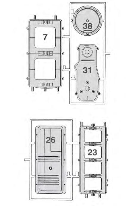
10 Fitting the rocker arms to the rocker shaft 17 Remove the eight rocker arms (part 24) from the carrier frame. Slide the rocker arms on to the metal rocker shaft (3mm diameter/156mm long). The arms must be fitted as shown in the diagram. Note that each successive rocker arm is fitted the opposite way round to the previous arm. Also carefully note the position of the rocker arms in relation to the upper cylinder head - use the studs on either end of the head as a point of reference. Assembling Your Engine Fitting the cylinder head gasket to the cylinder block 20 Place the cylinder head gasket (part 10) over the cylinder block, using the holes in the gasket to ensure correct alignment. Fitting the rocker arm assembly to the upper cylinder head 18 Lower the rocker arm assembly on to the upper cylinder head (part 23). Use your fingers to separate the rocker arms into pairs on the shaft, so they fit into the four rectangular holes in the head. The longer arms of the rockers must be positioned over the valve stems. Fitting the lower cylinder head to the cylinder block 21 Fit the lower cylinder head to the cylinder block. Make sure the end of the cylinder head with the round stud is fitted at the end of the block with the five studs sticking out. 22 Secure the cylinder head to the block using six screws. 19 Fit the bearing caps (part 25) as shown using ten screws. Do not overtighten, and check that all rocker arms move smoothly
, in the following order-a,b,c,d,e,f,g and H. Each cam will only fit in one position.")
.")
11 Assembling the camshaft 23 Remove the eight cams (labelled A to H) from the plastic carrier frame. Slide the cams onto the camshaft (3mm diameter/206 mm long), in the following order-a,b,c,d,e,f,g and H. Each cam will only fit in one position. There is a flat surface on the inside of each (refer to the enlarged portion of the diagram), which matches the flat surface on the camshaft. Please also note the rib on one end of each cam. The cams must be fitted so the ribbed portions all face one way (towards the left in the diagram). Assembling Your Engine Fitting the upper cylinder head to the lower cylinder head 26 Fit the upper cylinder head assembly (from step 19) to the engine. The end with the two wider spaced studs should be positioned over the end of the cylinder block with three studs sticking out. Check that all of the rocker arms are positioned over the top of the valve stems. Push down on each rocker arm to make sure that they move their corresponding valve. Secure the upper cylinder head with four screws. Fitting the camshaft to the lower cylinder head 24 Position the engine so the longer, splined (ribbed) end of the crankshaft is on your left. 25 Hold the camshaft with cam H on your left, and then lower on to the cylinder head. Use your fingers to separate the cams into pairs, so that each pair fits between the bearings in the head. The cam shaft should rest in each of the five bearing surfaces. Again, make sure that the raised ribs on the cams all point towards the longer end of the crankshaft. Fitting the rocker cover 27 Fit the rocker cover to the top of the cylinder head and secure with six screws. Fitting the crankshaft sprocket 28 Push the crankshaft sprocket (part 27) on to the longer, splined end of the crankshaft, with the toothed side facing away from the engine. There is a slot in the sprocket that matches a rib on the crankshaft. Turn the sprocket, until it slides on smoothly
12 Assembling Your Engine Fitting the camshaft sprocket 29 Push the camshaft sprocket (part 28) on to the camshaft, again making sure that the toothed side faces away from the engine. The flat in the hole in the sprocket lines up with the flat on the camshaft. Fitting the timing alignment tool 30 The alignment tool is used to lock the crankshaft and camshaft sprockets in position while the timing belt is fitted. Carefully turn the sprockets until they are in the positions shown. Fit the alignment tool to the crankshaft sprocket first, followed by the camshaft sprocket. Fitting the timing belt and idler pulley 31 It is easier to complete this step with the engine held between your knees, so the sprockets are facing upwards. Carefully fit the timing belt on to the sprockets, making sure the teeth on the belt engage with the teeth on the sprockets. The belt should be tight between the sprockets on the right-hand side of the engine, with all slack on the left-hand side. The slack is taken up when the idler pulley is fitted. Push the idler pulley (part 30) against the smooth side of the timing belt and then slide it on to the stud on the end of the block, as shown, Once the timing belt and idler pulley have been fitted, remove the alignment tool, taking care not to dislodge the parts just fitted. Fitting the timing belt cover 32 Fit the timing belt cover (part 31) over the timing belt and sprockets and secure with four screws
13 Assembling Your Engine Fitting the water pump 33 Assemble the front and rear halves of the water pump (parts 33 and 32. Fit this to the three studs on the front of the timing belt cover, then secure with three screws. Refer to the illustration for guidance. 34 Fit the crankshaft pulley (part 36) to the crankshaft. The slot in the pulley must line up with the rib on the crankshaft in order to slide into position. Secure the pulley with a single screw and washer, as shown. Fitting the fan pulley, fan and fan belt 35 Fit the fan pulley (part 34) to the shaft on the front of the water pump. Fix the pulley to the pump using a single screw and washer, as shown. 36 Fix the fan (part 35) to the fan pulley using two screws. Note that the raised ribs on the fan blades face outward. 37 Carefully loop the fan belt over the fan blades so that it rests on the fan belt pulley. Pull the other end down and loop it over the crankshaft pulley. The toothed side of the belt should fit against the pulleys

14 Assembling Your Engine Fitting the flywheel 38 Fit the flywheel (part 37 - the toothed wheel) to the opposite end of the crankshaft to the crankshaft pulley. The toothed part of the flywheel should be positioned furthest away from the end of the engine. Positioning the pistons and camshaft 39 Gently turn the crankshaft by hand so that No. 4 piston (at the water pump/cam belt end of the engine, also marked on the side of the cylinder head) moves to its highest point the Top Dead Centre or TDC position. Check that the flat on the camshaft is facing downwards; if it is facing upwards, continue to rotate the crankshaft until No. 4 piston reaches its next TDC position Fitting the batteries 40 Fit 2 x AA/LR6 batteries to the base, making sure they are positioned in accordance with the markings in the compartment. Fitting the distributor 41 Fit the distributor to the end of the camshaft as shown, with the wires positioned at the top. Insert three screws into the corresponding lugs in the cylinder head, but DO NOT tighten them yet. Take care not to turn the camshaft. Connect the distributor to the battery box. Battery safety Non-rechargeable batteries are not to be recharged Rechargeable batteries are only to be charged under adult supervision Rechargeable batteries are to be removed from the toy before being recharged Different types of batteries or new and used batteries are not to be mixed Batteries are to be inserted with the correct polarity The supply terminals are not to be short circuited Do not dispose of batteries in the fire Always turn off the unit when changing batteries Exhausted batteries are to be removed from the toy Do not connect the toy to more than the recommended number of power supplies 22 23
15 Assembling Your Engine Adjusting the ignition timing 42 Follow the wire from the 4 marked on the distributor cap to the bulb (which represents the No. 4 spark plug). Hold the bulb, then adjust the ignition timing as follows: press the red button on the battery box and gently turn the distributor until the bulb is illuminated. Carefully tighten the three distributor securing screws. Check the ignition timing again to make sure the No. 4 bulb still illuminates. Fitting the spark plugs 43 Fit the No. 4 bulb to the hole marked 4 on the cylinder head, Follow the three other wires from the 1, 2 and 3 markings on the distributor cap to their respective bulbs, and fit these to the corresponding holes in the cylinder head
16 Assembling Your Engine Fitting the electric motor unit 44 Slide the motor unit into position over the flywheel, making sure that the gear on the motor and flywheel engage. The three mounting holes on the motor unit should line up with the studs on the engine, as shown. Secure the motor unit using three screws. Fitting the clutch cover 45 Feed the wire from the motor unit through the hole in the clutch cover (part 38). Fit the clutch cover to the engine, using three screws to secure it in place
 into position on the spark plug side of the engine, as shown.")
17 Assembling Your Engine Fitting the dipstick 48 Slide the dipstick (part 43) into the hole in the engine (below the inlet manifold, next to the clutch cover). Fitting the exhaust manifold 49 Push the exhaust manifold (part 42) into position on the spark plug side of the engine, as shown. Fitting the inlet manifold/throttle body assembly 46 Fit the throttle to the inlet manifold (part 40). Note the locating pin in the bottom of the throttle, and the corresponding hole in the manifold, as shown. Secure with a screw. 47 Push the manifold/throttle assembly to the engine, on the opposite side to the spark plugs
18 HOW A PETROL ENGINE WORKS Starting the engine 50 Plug both the distributor wires and electric motor unit into the base. Press the red Start button - the engine will run for approximately 45 seconds. You ve now built a working model of a real car engine, and you ve earned your Haynes Engineer Certificate, which you can download and print from Basic principles To explain how a full-size car engine works, we ll use a simplified version of a real engine - our model engine in fact. You can switch on your finished model as you read this explanation and it will help you to understand how a real engine works. The crankshaft is called a crankshaft because it is a cranked shaft - the shaft has four cranked sections and the piston/connecting rod assemblies connect to these cranked sections. As the crankshaft turns, the cranked sections rotate around the centreline of the crankshaft and this allows the pistons to move up and down as the crankshaft turns. When the piston moves down, it pushes the connecting rod down, which pushes against the cranked part of the crankshaft, making the crankshaft rotate. This converts the up-and-down movement of the piston into the turning movement of the crankshaft. The engine s crankshaft drives the transmissions, which includes various different components connected together whose job it is to drive the car s wheels, making the car move. Now let s look at how the engine works in more detail. We ll look at just one cylinder of the engine. A cylinder is the hollow cylinder inside the engine in which one piston moves up and down. The piston has seals, called piston rings, around its edge, which aren t shown on our model and these seals stop gases passing round the sides of the piston. Our model has four cylinders, like the most common full-size engines. When you turn the engine to start the car, the starter (a powerful electric motor, powered by the car s battery) turns the crankshaft, moving the pistons up and down. As a piston moves down from its highest position inside the cylinder (called Top Dead Centre or TDC ), a mixture of petrol and air is sucked into the space inside the cylinder above the piston. This is called the intake stroke. The starter continues to turn the crankshaft and, as the piston moves back up towards the top of its cylinder, the petrol/air mixture is compressed (squashed) in the space above the piston. This is called the compression stroke. As the piston reaches its highest point, a spark plug creates a spark above the piston and this spark ignites the petrol/air mixture, causing a small controlled explosion above the piston. The explosion pushes the piston downwards and this is called the power stroke. Once the piston has reached its lowest point, it starts to move back up its cylinder, pushing the burnt gases out through the top of the cylinder. This is called the exhaust stroke. So, the engine has four strokes; intake, compression, power and exhaust, or suck, squeeze, bang and blow to make it simpler. These four strokes make up the 4-stoke cycle. The petrol/air mixture flows into the space above the piston, called the combustion chamber.. The mixture flows in through a small hole which is opened and closed by the inlet valve. The burnt gas flows out of the cylinder through another hole which is opened and closed by the exhaust valve. The valves are normally held closed by springs, but as the engine turns the valves are pushed open in the correct order by the rocker arms, which are moved by the camshaft. The rocker arm pushes the valve down against its spring and, as the rocker moves up, the spring pushes the valve closed

19 How a petrol engine works 4-stroke cycle Exhaust valve closed Inlet valve open Inlet port Valves closed Valves closed Exhaust valve open Connecting rod Piston moves down sucking in petrol/air mixture Piston rises compressing petrol/air mixture Petrol/air mixture ignites Piston forced down by expanding gases Piston moves up forcing exhaust gases out of cylinder Crankshaft rotation The 1st stroke (intake) The piston starts off at the top of the cylinder. The exhaust valve is closed and the inlet valve is open. As the crankshaft turns and the piston moves down inside the cylinder, petrol/air mixture is sucked in through the inlet valve. When the piston reaches its lowest point inside the cylinder, the cylinder is filled with petrol/air mixture and the inlet valve closes. This is the end of the intake stroke. The 2nd stroke (Compression) At the start of the compression stroke, the piston is at its lowest point inside the cylinder and the inlet and exhaust valves are closed. The crankshaft continues turning and the piston moves upwards. As the piston moves upwards it squeezes (compresses) the petrol/air mixture and this increases the temperature of the mixture very quickly. When the piston reaches its highest point the mixture is fully compressed and this is the end of the compression stroke. The 3rd stroke (Power) The very high pressure and temperature inside the combustion chamber cause the petrol/air mixture to break up into very fine particles, like a mist. These are perfect conditions for burning a gas. All that s needed to start the burning (or combustion - a kind of controlled explosion) is a spark. A very high electrical voltage supplied to the spark plug causes a spark to jump across the gap at the end of the spark plug. This ignites the petrol/air mixture and starts the combustion. The force of the controlled explosion and the expanding gases forces the piston downwards, which pushes the crankshaft round. During the power stroke, three things happen to the petrol/air mixture - it ignites, combusts (burns) and expands. The expansion of the gas pushes the piston down, which transfers power to the crankshaft. When the piston reaches its lowest point inside the cylinder this is the end of the power stroke. The 4th stroke (Exhaust) As the piston starts to move up inside the cylinder again, the exhaust valve opens to allow the burnt (exhaust) gas to escape from the cylinder and as the piston moves up the cylinder it pushes the gas out through the exhaust valve. As the piston reaches the top of the cylinder the exhaust valve closes, the exhaust stroke ends and the 4-stroke cycle begins again with another intake stroke
20 How a petrol engine works Multi-cylinder engines So far, we ve explained how the engine works by describing what happens in one cylinder. A car engine will actually have more than just one cylinder - anything from two (quite rare) to 16 (in the most expensive high-performance cars), but the most common number for everyday cars is 4. If an engine had only one cylinder it would vibrate a lot and make a car very uncomfortable. To make the engine run smoothly, the spark plugs fire in a regular order called the firing order and for most four-cylinder engines the firing order is You can see this on the model engine by watching the spark plugs fire - No. 1 cylinder is the one closest to the distributor. The model engine You can see how the 4-stroke cycle works by starting your model engine and watching how the components inside move. Watch how the camshaft and rockers move the valves as each piston moves up and down inside its cylinder. If you watch the piston in one cylinder, you should be able to recognise the four strokes - watch the valves and see if you can tell which stroke is which. Remember that: On the intake stroke the piston moves down, the inlet valve is open and the exhaust valve is closed. On the compression stroke, the piston moves up and the inlet and exhaust valves are closed. On the power stroke, the piston moves down and the inlet and exhaust valves are closed. On the exhaust stroke, the piston moves up, the inlet is closed and the exhaust valve is open. The exhaust valves are all on the exhaust manifold side of the engine and the inlet valves are on the inlet manifold/throttle body side. You ll notice that all four cylinders in the model engine are on different strokes - watch how the pistons move as the crankshaft turns and you ll see that the pistons move in pairs and, when two of the pistons are at the tops of their cylinders, the other two are at the bottom. Even though two of the pistons may be at the tops of their cylinders, the pistons will be on different strokes - one will be about to move down at the start of its intake stroke and the other will be about to move down at the start of its power stroke. You can tell which piston is about to start of its power stroke because the spark plug will fire (the bulb will light) in the cylinder head above the piston which has just reached the end of its compression stroke and is just about to start its power stroke. What does the ignition system do? The ignition system produces the sparks which are used to ignite the petrol/air mixture in a petrol engine (diesel engines don t have an ignition system). The ignition coil changes the low voltage electricity from the battery into high-voltage electricity which is sent along the HT (High Tension) leads to the spark plugs.the spark plugs are screwed into the cylinder head and produce sparks inside the combustion chambers. What does the fuel injection system do? All modern petrol engines are fitted with a fuel injection system. There are two basic types of fuel injection system, single-point and multi-point. A single-point fuel injection system has a single fuel injector which sprays petrol into the inlet manifold where it s mixed with air before passing into through the engine s inlet valves into the cylinders. A multi-point fuel injection system works in exactly the same way, except that a separate fuel injector is used to fuel each cylinder. What do emissions control systems do? When the petrol/air mixture is burnt inside the engine, exhaust gases are produced. The exhaust gases pass through the car s exhaust system out into the atmosphere, causing pollution. These gases are known as exhaust emissions and all engines have emissions control systems fitted to reduce harmful pollution. What does an engine management system do? An engine management system is controlled by an electronic control unit (ECU) which is connected to various sensors and actuators fitted around the engine. The sensors monitor the engine operating conditions and produce electrical signals which are sent to the ECU. The ECU processes all the information from the sensors and is able to tell exactly what conditions the engine is running under. The ECU then sends signals to the ignition, fuel injection and emission control systems to control the engine. An engine management system allows very fine control of the engine and the ECU makes sure that the engine operates as efficiently and smoothly as possible, which means that it uses less fuel and causes less pollution. Why does an engine need oil? Oil is the engine s blood. The engine needs oil for two reasons - to reduce the friction between the moving parts and to help keep the engine cool. Some of the metal components inside the engine move at a very high speed very close together, and they rely on a thin film of oil between them to prevent the components from rubbing together. If the components rub together they will very quickly overheat and seize up, which can wreck the engine. When the engine is stopped, the oil is stored in a tray called the sump, bolted to the bottom of the cylinder block. When the engine is running, the oil is pumped from the sump to all moving parts of the engine through small passages in the cylinder block and cylinder head. The oil pump is driven by the engine, usually from the crankshaft. As the oil circulates through the engine, it picks up tiny particles of dirt and, as the engine wears, tiny particles of metal, which would eventually damage the engine s moving parts. The oil passes through an oil filter which catches these small particles; the oil filter is one of the most important parts of the engine. Eventually, the oil filter starts to clog up and the oil can t flow through as easily, so it must be changed whenever the engine oil is changed at the recommended service intervals. The amount of oil inside the engine can be checked using a dipstick - if the oil level is low it can damage the engine very quickly. If the oil level is checked often and the oil and filter are changed at the recommended intervals, the engine will stay healthy. Why does the engine have a cooling system? Why does the engine have a cooling system? The cooling system is vital because it stops the engine overheating. It also keeps the engine at the best temperature for it to work efficiently, which means that it will use less petrol and will produce less harmful exhaust emissions. The coolant is pumped around the passages inside the engine by the coolant (water) pump, collecting heat from the engine components as it flows through. The 34 35
21 hot coolant then passes from the engine to the radiator (mounted at the front of the car under the bonnet), where the air is forced through the radiator as the car moves forward and cools it. The cooling fan draws cool air over the radiator when the speed of the car is too low (or if the car is stopped), or if the air temperature is too high to give enough cooling. The cooling pump is usually driven by a belt, sometimes by the timing belt and sometimes by a separate auxiliary (or fan ) belt. What s the difference between a petrol engine and a diesel engine? Most types of cars now come with the option of a petrol or diesel engine. Diesel engines use diesel fuel instead of petrol and the biggest difference in the way petrol and diesel engines work is the way that the fuel burns. A petrol engine needs a spark plug to ignite the petrol with a spark but in a diesel engine there s no spark plug and the fuel ignites itself due to the high pressure and temperature inside the combustion chamber. Because diesel engines need a high temperature to ignite the fuel, when they are first started from cold they use glow plugs to heat the fuel/air mixture to a high enough temperature to ignite. Generally, diesel engines use less fuel than petrol engines and they produce less pollution. So, now you have a good idea of how an engine works. KEEPING A CAR AND ITS ENGINE HEALTHY There are a few simple checks that can be done once a week to keep a car and its engine in good condition. These checks will only take about ten minutes and the handbook that comes with the car, or the right Haynes Service and Repair Manual for the car, will explain how to carry out these checks. You can also see how to carry out these checks on the Haynes website at Weekly checklist: Check the engine oil level Check the engine coolant level Check the brake fluid level Check the windscreen washer fluid level, and check that the washers and windscreen wipers work Check that the wiper blades are in good condition Check the tyre pressures and check that the tyres aren t damaged or worn Check the power steering fluid level, if the car has power steering REDUCING POLLUTION AND SAVING ON FUEL BILLS Using less fuel saves money and also reduces pollution and it s easy to do both by bearing in mind a few simple points. All the following points increase the amount of fuel used and so increase pollution. Towing a trailer or caravan and carrying heavy loads Driving the car with a roofbox or roof bars fitted Lots of short journeys Driving with low tyre pressures So, if the driver thinks about all these points it s easy to cause less pollution and save money too! For more information on things you can easily do to help reduce the pollution a car causes, see the Haynes website at
22 BASIC ENGINE TERMS Basic engine terms Here s a list of common terms connected with a car engine, with simple explanations of what they mean. Air filter A paper or foam filter that removes dirt from the air that s sucked into the engine. Alternator An electrical generator driven by the engine. It provides electricity for the car s electrical system when the engine s running, and to charge the battery. Antifreeze A fluid that s added to water to produce engine coolant. The antifreeze stops the coolant freezing in cold weather and prevents corrosion inside the engine. Battery A reservoir that stores electricity. Provides the power to start the engine and power for the electrical systems when the engine is stopped, and is charged by the alternator when the engine s running. Bearing A metal or other hard-wearing surface that another part moves against. A bearing is designed to reduce friction and wear and is usually lubricated with oil or grease. Big-end The lower end of a connecting rod attached to the engine s crankshaft. It has a bearing and transmits the movement of the connecting rod to the crankshaft. Bore A term used to describe the diameter of a cylinder in an engine. Breather An opening or valve that allows air or fumes out of the engine, or fresh air into the engine. Cam belt See Timing Belt. Cam follower (tappet) A component fitted between the camshaft and a valve to operate the valves. Camshaft A rotating shaft driven from the crankshaft, with cams that push the valves open. Catalytic converter A device fitted in the exhaust system that reduces the amount of harmful gases released into the atmosphere. Clutch A part that allows two separate rotating components to be coupled together smoothly, without the need for either component to stop moving. Combustion chamber A shaped area into which the fuel/air mixture is compressed by the piston and where the mixture is ignited. The combustion chamber may be in the cylinder head, or sometimes in the top of the piston. Compression ratio (CR) A term to describe the amount by which the fuel/air mixture is compressed as a piston moves from the bottom to the top of its travel. Connecting rod (con rod) A metal rod in the engine connecting a piston to the crankshaft. The connecting rod transfers the up-and-down motion of the piston to the crankshaft. Coolant A mixture of water and antifreeze, used in a car s engine cooling system. Coolant (water) pump A pump driven by the engine that pumps the coolant around the cooling system. Cooling fan Electric or engine-driven fan mounted at the front of the engine compartment and designed to cool the radiator. Crankcase The area of the cylinder block below the pistons, which houses the crankshaft. Crankshaft A cranked metal shaft that changes the up-and-down motion of the pistons and connecting rods into a rotary motion. Cylinder A metal tube in the engine in which a piston slides. Cylinder block The main engine casing, which houses the cylinders, crankshaft, pistons and connecting rods. Cylinder head The casing at the top of the engine that houses the valves and valve gear. The cylinder head is bolted to the cylinder block. Cylinder head gasket The gasket that makes a seal between the cylinder head and the cylinder block. Dipstick A metal or plastic rod used to check the engine oil level. Distributor A device used to distribute the ignition HT circuit current to the individual spark plugs. DOHC Double Overhead Camshafts. An engine with two camshafts, where one operates the inlet valves, and the other operates the exhaust valves. Drivebelt A belt, usually made from rubber, used to transmit drive between two pulleys or sprockets. Often used to drive the camshafts and engine ancillaries. Emissions Harmful substances (gases or particles) released into the atmosphere from a car s engine. Emissions control A way of reducing the emissions released into the atmosphere. Engine management system A system which uses an electronic control unit to control the ignition system and fuel injection system, improving engine efficiency and reducing emissions. Exhaust manifold A ducting used for directing the exhaust gases from the engine s cylinder head into the exhaust system. Fan belt Another term for a drivebelt. Fault code An electronic code stored in the memory of an electronic control unit which gives details of a fault detected by the self-diagnostic system. A diagnostic light on the instrument panel will usually come on to indicate a fault. Firing order The order in which the pistons in the cylinders of an engine reach their firing points. Firing point The instant at which the fuel/air mixture in the cylinder of an engine ignites in the combustion chamber. Flywheel A heavy metal disc attached to one end of the crankshaft in an engine, used to smooth out the power pulses from the pistons. Four-stroke A term used to describe the four operating strokes of a piston in a car engine. Fuel injection A method of injecting a measured amount of fuel into an engine. Fuel injector A device used to inject fuel into an engine. Some engines use a single fuel injector, whilst some use one fuel injector for each cylinder of the engine. Gasket A material used between two surfaces to give a leakproof joint. Glow plug An electrical heating device fitted to a diesel engine to help the engine start from cold. Head gasket (cylinder head gasket) A gasket fitted to provide a leakproof seal between an engine s cylinder block and cylinder head. Ignition coil An electrical coil that generates the high voltage needed in a petrol engine Ignition system to fire the spark plugs. Ignition system The electrical system that controls the spark used to ignite the petrol/air mixture in a petrol engine. Ignition timing A measure of the instant in the cylinder firing cycle at which the ignition spark (provided by the spark plug) happens in an petrol engine. Inlet manifold A ducting, usually made of metal or plastic. which directs the air, or fuel/air mixture into the engine s cylinder head. Mixture The fuel/air mixture burnt by an engine to produce power. Oil filter A renewable filter that removes dirt from engine oil
23 Oxygen sensor (lambda sensor) Provides information on the amount of oxygen in the exhaust gases. Used to enable the engine management system to control the petrol/air mixture. Piston Cylindrical component which slides in a close-fitting cylinder. The pistons in an engine compress the fuel/air mixture, transmit power to the crankshaft through the connecting rods, and push the burnt gases out through the exhaust valves. Piston ring A hardened metal ring that fits in a groove running around a piston. The piston ring ensures a gas-tight seal between the piston and the cylinder. Radiator A cooling device, usually positioned at the front of the car, through which the hot coolant is passed. As the car moves forward, the airflow cools the coolant in the radiator. Rocker arm A lever used in an engine s valve-operating mechanism which rocks on a pivot, with one end moved up and down by the camshaft and the other end operating a valve. Spark plug A device that provides the spark in a petrol engine s combustion chamber to ignite the petrol/air mixture. Starter motor An electric motor used to start the engine. Stroke The total distance travelled by a single piston in a cylinder when it moves from the bottom to the top of the cylinder. Tappet - See Cam follower. Timing belt (cam belt) Toothed drivebelt, used to transmit drive from the crankshaft to the camshaft. Thermostat A device that helps the engine to warm up by stopping the coolant from flowing through the radiator until a certain temperature is reached. Top Dead Centre (TDC) The exact point when a piston is at the top of its stroke. Turbocharger A device that forces air into the engine. This pushes more fuel/air mixture into the engine and increases the engine s power. Twin-cam Abbreviation for twin overhead camshafts - see DOHC. Valve A device that opens and closes to stop or allow gas or liquid to flow. Valve Clearance The clearance between the top of a valve and the camshaft. Valve lifter See Cam follower. 16-valve A term used to describe a four-cylinder engine with four valves in each cylinder, usually two exhaust and two inlet valves. Vee-engine An engine design where the cylinders are arranged in two rows, forming a V when viewed from one end. For example, a V8 has two rows of four cylinders each. Sump The main reservoir for the engine oil. Bolted to the bottom of the engine.
Handout Activity: HA170
 Basic diesel engine components Handout Activity: HA170 HA170-2 Basic diesel engine components Diesel engine parts are usually heavier or more rugged than those of similar output gasoline engines. Their
CHAPTER 1 MECHANICAL ARRANGEMENT
 CHAPTER 1 CHAPTER 1 MECHANICAL ARRANGEMENT CONTENTS PAGE Basic Principals 02 The Crankshaft 06 Piston Attachment 08 Major Assemblies 10 Valve Gear 12 Cam Drive 18 Mechanical Arrangement - Basic Principals
Internal Combustion Engines
 Internal Combustion Engines The internal combustion engine is an engine in which the burning of a fuel occurs in a confined space called a combustion chamber. This exothermic reaction of a fuel with an
Internal Combustion Engines.
 Internal Combustion Engines. Here's a quick description of a typical internal combustion engine, along with basic vocabularies that describe the components and their functions. This stuffs serve as a quick
TKP3501 Farm Mechanization
 TKP3501 Farm Mechanization Topic 2: Internal Combustion Engines Ahmad Suhaizi, Mat Su Email: asuhaizi@upm.edu.my Outlines Internal vs external combustion engines Engine structure Combustion cycle 4 stroke
T erm STI2D. The process by which a car works is a lot simpler than you may think. When a driver turns a key in the ignition:
 1. How a car engine Works The process by which a car works is a lot simpler than you may think. When a driver turns a key in the ignition: The car battery powers up sending Power to the starter motor,
ENGINE & WORKING PRINCIPLES
 ENGINE & WORKING PRINCIPLES A heat engine is a machine, which converts heat energy into mechanical energy. The combustion of fuel such as coal, petrol, diesel generates heat. This heat is supplied to a
Fuel and exhaust systems 4A 21
 Fuel and exhaust systems 4A 21 15.40 Unscrew the union nuts and disconnect the fuel feed and return hoses from the manifold 41 Disconnect the injector wiring harness connector and the vacuum hose from
Modern Auto Tech Study Guide Chapter 11 Pages Engine Fundamentals 62 Points
 Modern Auto Tech Study Guide Chapter 11 Pages 145-161 Engine Fundamentals 62 Points 1. The is the area between the top of the piston & the cylinder head. Combustion Chamber Cylinder Chamber Chamber of
Engine Dismantle and Assemble ( )
") Engine Dismantle and Assemble ( 34 8) Special Tools 5 053 Slide hammer 47 Vibration damper remover 47 5053 00 Splined head socket, cylinder head bolts 87 Mounting stand with geared drive 00 059C Installer
Engine Dismantle and Assemble ( 34 8) Special Tools 5 053 Slide hammer 47 Vibration damper remover 47 5053 00 Splined head socket, cylinder head bolts 87 Mounting stand with geared drive 00 059C Installer
UNIT IV INTERNAL COMBUSTION ENGINES
 UNIT IV INTERNAL COMBUSTION ENGINES Objectives After the completion of this chapter, Students 1. To know the different parts of IC engines and their functions. 2. To understand the working principle of
Lab #5 4-Cylinder Single Overhead Cam Engine Dissection
 Engr 3 Mission College Faculty: Kate Disney TA: Andrew Dina Lab #5 4-Cylinder Single Overhead Cam Engine Dissection Equipment: 4-Cylinder Mazda 16 Valve SOHC 92 (Manual Transmission) Ratchet with 2 and
1983 BMW 320i. 1.8L 4-CYL 1983 Engines - 1.8L 4-Cylinder Engines - 1.8L 4-Cylinder
 ENGINE IDENTIFICATION 1.8L 4-CYL 1983 Engines - 1.8L 4-Cylinder For engine repair procedures not covered in this article, see ENGINE OVERHAUL PROCEDURES - GENERAL INFORMATION article in the GENERAL INFORMATION
Comparative Study Of Four Stroke Diesel And Petrol Engine.
 Comparative Study Of Four Stroke Diesel And Petrol Engine. Aim: To study the construction and working of 4- stroke petrol / diesel engine. Theory: A machine or device which derives heat from the combustion
Bthird, or power stroke by the expanding gases. As the
 third, or power stroke by the expanding gases. As the piston reaches DC it enters the fourth cycle. The exhaust valve opens and the piston rises forcing burned gases from the combustion chamber in what
California State University, Bakersfield. Signals and Systems. Kristin Koehler. California State University, Bakersfield Lecture 4 July 18 th, 2013
 Kristin Koehler California State University, Bakersfield Lecture 4 July 18 th, 2013 1 Outline Internal combustion engines 2 stroke combustion engines 4 stroke combustion engines Diesel engines 2 Consists
Chapter 4 Part D: Fuel and exhaust systems - Magneti Marelli injection
 4D 1 Chapter 4 Part D: Fuel and exhaust systems - Magneti Marelli injection Contents Accelerator cable - removal and..................... 11 Air cleaner element - renewal..............................
Internal Combustion Engine
 Internal Combustion Engine The development of the internal combustion engine was made possible by the earlier development of the STEAM ENGINE. Both types of engines burn fuel, releasing energy from it
DrVanos.com Stage II Installation Instructions. Tool rental is available with the purchase of a vanos kit *See website for more info*
 DrVanos.com Stage II Installation Instructions Special Tools Needed: Camshaft locking tool TDC Crank pin Sprocket turning tool Tool rental is available with the purchase of a vanos kit *See website for
Timing Chain - Renew ( )
") «Scorpio '95 Table of Contents» «Section 21: Engine» «Subsection 21-05: 2,9 V6 24V Cosworth Engine» «REMOVAL AND INSTALLATION» Timing Chain - Renew (21 314 0) Special Tools 21-140-01Adaptor for 21-140
«Scorpio '95 Table of Contents» «Section 21: Engine» «Subsection 21-05: 2,9 V6 24V Cosworth Engine» «REMOVAL AND INSTALLATION» Timing Chain - Renew (21 314 0) Special Tools 21-140-01Adaptor for 21-140
SECTION D Engine 6.0L Diesel
 303-01D-i Engine 6.0L Diesel 303-01D-i SECTION 303-01D Engine 6.0L Diesel CONTENTS PAGE DESCRIPTION AND OPERATION Engine... 303-01D-2 303-01D-2 Engine 6.0L Diesel 303-01D-2 DESCRIPTION AND OPERATION Engine
SPECIFICATIONS TEST AND ADJUSTMENT SPECIFICATIONS SPECIFICATIONS ENGINE FD620D, K SERIES
 ENGINE FD620D, K SERIES SPECIFICATIONS SPECIFICATIONS TEST AND ADJUSTMENT SPECIFICATIONS Engine Oil Pressure Sensor Activates............................... 98 kpa (14.2 psi) Oil Pressure While Cranking
ENGINES ENGINE OPERATION
 ENGINES ENGINE OPERATION Because the most widely used piston engine is the four-stroke cycle type, it will be used as the example for this section, Engine Operation and as the basis for comparison in the
Engine Dismantle and Assemble ( )
") Engine Dismantle and Assemble (2 34 8) Special Tools 2-036A Remover for pilot bearing 2-37 Oil seal installer/aligner 237 2036A 2-044A Installer/Aligner, Pilot Bearing/Clutch Plate 244 2-44 Inlet manifold
Engine Dismantle and Assemble (2 34 8) Special Tools 2-036A Remover for pilot bearing 2-37 Oil seal installer/aligner 237 2036A 2-044A Installer/Aligner, Pilot Bearing/Clutch Plate 244 2-44 Inlet manifold
THE WOLSELEY "VIPER" AERO ENGINE. (Hispano-Suiza W.4.A*)
") 13 THE WOLSELEY "VIPER" AERO ENGINE. (Hispano-Suiza W.4.A*) General description. The engine referred to in this article is the Hispano-Suiza 180 hp W.4.A* Aero Engine, as made by Wolseley Motors Ltd. The
13 THE WOLSELEY "VIPER" AERO ENGINE. (Hispano-Suiza W.4.A*) General description. The engine referred to in this article is the Hispano-Suiza 180 hp W.4.A* Aero Engine, as made by Wolseley Motors Ltd. The
CHAPTER 3 ENGINE TYPES
 CHAPTER 3 CHAPTER 3 ENGINE TYPES CONTENTS PAGE Multi-Cylinders 02 Firing orders 06 2 Stroke Cycle 08 Diesel Cycle 10 Wankel Engine 12 Radial/Rotary 14 Engine Types Multi Cylinders Below are illustrated
Cylinder Head, Remove and Install (Z 22 SE)
") Page 1 of 29 Cylinder Head, Remove and Install (Z 22 SE) Remove 1. Open the bonnet. 2. Disconnect the battery. 3. Open the engine cover (1). 4. Detach the engine cover. 6 bolts (2) and (3) 5. Release the
Page 1 of 29 Cylinder Head, Remove and Install (Z 22 SE) Remove 1. Open the bonnet. 2. Disconnect the battery. 3. Open the engine cover (1). 4. Detach the engine cover. 6 bolts (2) and (3) 5. Release the
THE FOUR STROKE CYCLE BUT HOW DOES IT WORK EXACTLY? LET S LOOK IN MORE DETAIL 1. INDUCTION SUCK 2. COMPRESSION 3. COMBUSTION 4.
 THE FOUR STROKE CYCLE BUT HOW DOES IT WORK EXACTLY? WE KNOW ABOUT:- WHICH WE KNOW AS:- LET S LOOK IN MORE DETAIL 1. INDUCTION SUCK 2. COMPRESSION 3. COMBUSTION 4. EXHAUST SQUEEZE BANG BLOW Inlet valve
 Page 1 of 9 303-01C Engine 6.0L Diesel 2004 F-Super Duty 250-550/Excursion DESCRIPTION AND OPERATION Procedure revision date: 08/06/2003 Engine Printable View Engine Description The 6.0L diesel engine
Fundamentals of Small Gas Engines
 Fundamentals of Small Gas Engines Objectives: Describe the four-stroke cycle engine operation and explain the purpose of each stroke Explain the concept of valve timing Describe two-stroke engine operation
Timing Chain Renew ( ) Renew. Section Title. Special Tools. Proprietary Tools Scraper Engine support bar
 Renew. Section Title. Special Tools. Proprietary Tools Scraper Engine support bar") Timing Chain Renew ( 34 0) Special Tools 40 400 40 Engine support bar 40 0 Adaptor for -40 40 03 Adaptor for -40 Proprietary Tools Scraper Workshop Equipment Transmission jack Materials Cable ties Sealer
Timing Chain Renew ( 34 0) Special Tools 40 400 40 Engine support bar 40 0 Adaptor for -40 40 03 Adaptor for -40 Proprietary Tools Scraper Workshop Equipment Transmission jack Materials Cable ties Sealer
FUNDAMENTAL OF AUTOMOBILE SYSTEMS
 Prof. Kunalsinh Mechanical Engineering Dept. FUNDAMENTAL OF AUTOMOBILE SYSTEMS Prof. Kunalsinh kathia [MECHANICAL DEPT.] UNIT-2 [ENGINES] PART-1 Prof. Kunalsinh kathia [MECHANICAL DEPT.] Internal combustion
Preventive maintenance 4
 00 Series Preventive maintenance Preventive maintenance periods Use the procedures in this chapter to maintain your engine in accordance with the preventive maintenance schedule. Check the periods given
SPECIFICATIONS TEST AND ADJUSTMENT SPECIFICATIONS SPECIFICATIONS ENGINE FD620D, K SERIES
 TEST AND ADJUSTMENT Engine Oil Pressure Sensor Activates............................... 98 kpa (14.2 psi) Oil Pressure While Cranking (Minimum).......................... 28 kpa (4 psi) Oil Pressure.....................................
This is a guide to assist you adjust the valve clearance on a 2l V6 MIVEC engine found in a Mitsubishi FTO GPX
 Adjusting the valve clearance on a 2L V6 FTO engine This is a guide to assist you adjust the valve clearance on a 2l V6 MIVEC engine found in a Mitsubishi FTO GPX Disclaimer: This guide is to assist you
1992 Toyota Cressida
 Monday, May 16, 2016 5:32:47 PM Page 13 2005 Mitchell Repair Information Company, LLC. Fig. 7: Exploded View Of Typical Cylinder Head & Components Fig. 8: Cylinder Head Bolt Removal Sequence Monday, May
Chapter 14 Small Gas Engines
 Chapter 14 Small Gas Engines Use the Textbook Pages 321 349 to help answer the questions Why You Learn So Well in Tech & Engineering Classes 1. Internal combustion make heat by burning a fuel & air mixture
Removing and installing cylinder head
 31 30 29 28 27 26 25 24 23 22 1 2 3 11 12 10 4 9 5 6 7 8 Removing and installing cylinder head Checking compression pressure page 15-24. Notes: When installing a replacement cylinder head with a mounted
1991 Volkswagen Vanagon Syncro
 corner of radiator. See Fig. 1. Fig. 1: Bleeding Cooling System 2. Open bleeder valve in engine compartment (turn counterclockwise). See Fig. 1. Fill expansion tank until full. Start and run engine at
 Special Tools Needed: DrVanos.com Stage I Installation Instructions Camshaft locking tool TDC Crank pin Sprocket turning tool Tool rental is available with the purchase of a vanos kit *See website for
Engine Systems. Basic Engine Operation. Firing Order. Four Stroke Cycle. Overhead Valves - OHV. Engine Design. AUMT Engine Systems 4/4/11
 Advanced Introduction Brake to Automotive Systems Diagnosis Service and Service Basic Engine Operation Engine Systems Donald Jones Brookhaven College The internal combustion process consists of: admitting
CB500X Valve Checking/Adjustment Guide. Before starting:
 Before starting: Removing the tank is much easier when it doesn t have much fuel in it. Consider running the tank to a low petrol level before starting the job. Forum members in both the UK & USA have
Driver Driven. InputSpeed. Gears
 Gears Gears are toothed wheels designed to transmit rotary motion and power from one part of a mechanism to another. They are fitted to shafts with special devices called keys (or splines) that ensure
Task 4: Read the texts, look at the illustrations and do the activities below.
 Task 4: Read the texts, look at the illustrations and do the activities below. 4 BASIC OPERATIONS The Induction Stroke On the induction stroke, the inlet valve opens and the piston, moving down, creates
Two Cycle and Four Cycle Engines
 Ch. 5 Two Cycle and Four Cycle Engines Feb 20 7:43 AM 1 Stroke of the piston is its movement in the cylinder from one end of its travel to the other Feb 20 7:44 AM 2 Four stroke cycle engine 4 strokes
HOW - TO EMISSION CONTROL BASICS EMISSION CONTROL BASICS
 HOW - TO EMISSION CONTROL BASICS EMISSION CONTROL BASICS Tool And Material Checklist Bore Brush Thermometer Portable Vacuum Pump Screwdriver Combination Wrench Set 3/8 Drive Socket Set Tachometer Rag Service
ENGINE 6G74 3.5L-SOHC-24 VALVE
 11A ENGINE General Information/Service Specifications ENGINE 6G74 3.5L-SOHC-24 VALVE GENERAL INFORMATION Items Specifications Type V-type, Over Head Camshaft Number of cylinders 6 Bore mm 93.0 Stroke mm
PARTIAL ENGINE ASSY (2TR FE)
") COMPONENTS 147 1421Z01 Clip Hood Subassy x9 Radiator Support to Frame Seal LH 30 (306, 22) 30 (306, 22) Fan and Generator V Belt 5.0 (51, 44 in. lbf) Fan Shroud Fan Pulley Fan w/ Fluid Coupling PRE RUNNER
COMPONENTS 147 1421Z01 Clip Hood Subassy x9 Radiator Support to Frame Seal LH 30 (306, 22) 30 (306, 22) Fan and Generator V Belt 5.0 (51, 44 in. lbf) Fan Shroud Fan Pulley Fan w/ Fluid Coupling PRE RUNNER
EMISSION CONTROL (AUX. EMISSION CONTROL DEVICES) H4DOTC
 H4DOTC") EMISSION CONTROL (AUX. EMISSION CONTROL DEVICES) H4DOTC SYSTEM OVERVIEW 1. System Overview There are three emission control systems, which are as follows: Crankcase emission control system Exhaust emission
EMISSION CONTROL (AUX. EMISSION CONTROL DEVICES) H4DOTC SYSTEM OVERVIEW 1. System Overview There are three emission control systems, which are as follows: Crankcase emission control system Exhaust emission
Disassembly and Assembly
 K EN R 623 2-00 August 2006 Disassembly and Assembly 2506-15 Industrial Engine M G A (Engine) MGB (Engine) M G D (Engine) Important Safety Information Most accidents that involve product operation, maintenance
SAMPLE STUDY MATERIAL
 IC Engine - ME GATE, IES, PSU 1 SAMPLE STUDY MATERIAL Mechanical Engineering ME Postal Correspondence Course Internal Combustion Engine GATE, IES & PSUs IC Engine - ME GATE, IES, PSU 2 C O N T E N T 1.
A. Aluminum alloy Aluminum that has other metals mixed with it.
 ENGINE REPAIR UNIT 1: ENGINE DESIGN LESSON 1: PRINCIPLES OF ENGINE DESIGN I. Terms and definitions A. Aluminum alloy Aluminum that has other metals mixed with it. B. Bearing A device that allows movement
ENGINE OVERHAUL <2.4L ENGINE>
 11B-1 GROUP 11B ENGINE OVERHAUL CONTENTS SPECIAL TOOLS 11B-2 GENERATOR AND IGNITION SYSTEM 11B-6 REMOVAL AND INSTALLATION 11B-6 EXHAUST MANIFOLD 11B-9 REMOVAL AND INSTALLATION 11B-9 TIMING
Disassembly and Assembly
 SENR9973-01 September 2007 Disassembly and Assembly 400C Industrial Engine HB (Engine) HD (Engine) HH (Engine) HL (Engine) HM (Engine) HN (Engine) HP (Engine) HR (Engine) Important Safety Information Most
ENGINE OVERHAUL GROUP 11B 11B-1 CONTENTS GENERAL SPECIFICATIONS... 11B-2 OIL PAN AND TIMING CHAIN CASE... 11B-27 SERVICE SPECIFICATIONS...
 11B-1 GROUP 11B CONTENTS GENERAL SPECIFICATIONS 11B-2 SERVICE SPECIFICATIONS 11B-2 FASTENER TIGHTENING SPECIFICATIONS 11B-4 SEALANTS AND ADHESIVES 11B-7 SPECIAL TOOLS 11B-8 GENERATOR AND IGNITION SYSTEM
ENGINE OVERHAUL <2.4L ENGINE>
 11B-1 GROUP 11B ENGINE OVERHAUL CONTENTS GENERAL SPECIFICATIONS 11B-2 SERVICE SPECIFICATIONS 11B-2 REWORK DIMENSIONS 11B-3 TORQUE SPECIFICATIONS 11B-4 SEALANTS 11B-7 SPECIAL TOOLS 11B-8 GENERATOR
Cylinder head/gasket, replacing
 1(16) Cylinder head/gasket, replacing Special tools: 951 2666, 951 2767, 999 5450, 999 5452, 999 5454, 999 5670, 999 5718, 999 5719, 999 5750, 999 5972 Removing the cylinder head gasket Note! As the illustrations
SECTION 6A1-2 - ENGINE MECHANICAL - V6 SUPERCHARGED
 SECTION 6A1-2 - ENGINE MECHANICAL - V6 SUPERCHARGED CAUTION: This vehicle will be equipped with a Supplemental Restraint System (SRS). A SRS will consist of either seat belt pre-tensioners and a driver
Automobile section, showing different parts in detail. and miscellaneous devices.
 SECTION VII Nos. 97 112 Automobile section, showing different parts in detail. and miscellaneous devices. Hydraulic jack MECHANICAL MODELS 43 Section VII 97. Automobile engine starter. This device known
Inside a typical car engine. Almost all cars today use a reciprocating internal combustion engine because this engine is:
 Tech Torque HOW PETROL ENGINES WORK The Basics The purpose of a gasoline car engine is to convert gasoline into motion so that your car can move. Currently the easiest way to create motion from gasoline
Introduction to I.C Engines CH. 1. Prepared by: Dr. Assim Adaraje
 Introduction to I.C Engines CH. 1 Prepared by: Dr. Assim Adaraje 1 An internal combustion engine (ICE) is a heat engine where the combustion of a fuel occurs with an oxidizer (usually air) in a combustion
Remove Air Cleaner Cover and. Filter
 Remove Air Cleaner Cover and Inspect paper filter for tears Foam pre-cleaner is washable if equipped Replace if necessary Filter Remove Trim Panel Pull throttle lever knob off Remove 3, 8mm screws Remove
Pistons and Connecting Rods, Remove and Install
 Page 1 of 46 Pistons and Connecting Rods, Remove and Install Remove 1. Open the bonnet. 2. Disconnect the battery. 3. Open the engine cover (1). 4. Detach the engine cover. 6 bolts (2) and (3) 5. Release
ENGINE OVERHAUL <2.4L ENGINE>
 11D-1 GROUP 11D ENGINE OVERHAUL CONTENTS GENERAL SPECIFICATIONS 11D-2 SERVICE SPECIFICATIONS 11D-2 REWORK DIMENSIONS 11D-3 TORQUE SPECIFICATIONS 11D-4 SEALANTS 11D-7 SPECIAL TOOLS 11D-8 GENERATOR
MITSIBUSHI FTO NUT,BOLT AND TORQUE GUIDE
 MITSIBUSHI FTO NUT,BOLT AND TORQUE GUIDE All information below has been obtained from the official Mitsubishi fto workshop manual, and I hold no liability for any incorrect information. Heads marked 4
GLOSSARY. Block. Cylinders
 Engine The power source for any farm tractor is the engine. The engine provides the muscle for the power train and the hydraulic system. The typical modern farm tractor has a diesel engine ranging from
1.6L 4-CYL - VIN [E]
![1.6L 4-CYL - VIN [E]](/thumbs/81/84172348.jpg "1.6L 4-CYL - VIN [E]") 1.6L 4-CYL - VIN [E] 1993 Nissan Sentra 1993 NISSAN ENGINES 1.6L 4-Cylinder NX, Sentra * PLEASE READ THIS FIRST * NOTE: For engine repair procedures not covered in this article, see ENGINE OVERHAUL PROCEDURES
1.6L 4-CYL - VIN [E] 1993 Nissan Sentra 1993 NISSAN ENGINES 1.6L 4-Cylinder NX, Sentra * PLEASE READ THIS FIRST * NOTE: For engine repair procedures not covered in this article, see ENGINE OVERHAUL PROCEDURES
2.2L 4-CYL - VIN [S]
![2.2L 4-CYL - VIN [S]](/thumbs/72/67564355.jpg "2.2L 4-CYL - VIN [S]") 2.2L 4-CYL - VIN [S] 1994 Toyota Celica 1994 ENGINES Toyota 2.2L 4-Cylinder Celica NOTE: For repair procedures not covered in this article, see ENGINE OVERHAUL PROCEDURES - GENERAL INFORMATION article
2.2L 4-CYL - VIN [S] 1994 Toyota Celica 1994 ENGINES Toyota 2.2L 4-Cylinder Celica NOTE: For repair procedures not covered in this article, see ENGINE OVERHAUL PROCEDURES - GENERAL INFORMATION article
Engine Project. These engines are typically used in lawn mowers, snow blowers, go-carts, etc
 Engine Project Your team is going to dissect and assemble a 3.5 HP single cylinder, 4 cycle engine, made by Briggs and Stratton in Milwaukee, Wisconsin These engines are typically used in lawn mowers,
Tech Talk. Timing Belt 6VD1/6VE1
 Holden DOHC V6 Frontera 6VD1 3.2L 1999 2004 Jackaroo 6VE1 3.5L 1998 2004 Rodeo TF 6VD1 3.2L 1998 2003 Rodeo RA 6VE1 3.5L 2003 2005 Important: Read through all the instructions before proceeding with the
INTRODUCTION OF FOUR STROKE ENGINE
 INTRODUCTION OF FOUR STROKE ENGINE Engine: An engine is motor which converts chemical energy into mechanical energy Fuel/petrol engine: A petrol engine (known as a gasoline engine in North America) is
ENGINE MECHANICAL <134>
 11A-1 GROUP 11A ENGINE MECHANICAL CONTENTS GENERAL INFORMATION........ 11A-2.................. 11A-3 11A-2 The newly developed 1.1L 134910 engine features 3-cylinder, 12-valve, and double overhead
11A-1 ENGINE CONTENTS ENGINE <4G9>...
 11A-1 ENGINE CONTENTS 11109000276 ENGINE ... ENGINE ... 11A 11B 11A-2 ENGINE CONTENTS GENERAL INFORMATION... 3 SERVICE SPECIFICATIONS... 3 SEALANTS... 4 SPECIAL TOOLS... 5 ON-VEHICLE SERVICE...
Internal combustion engines can be classified in a number of different ways: 1. Types of Ignition
 Chapter 1 Introduction 1-3 ENGINE CLASSIFICATIONS Internal combustion engines can be classified in a number of different ways: 1. Types of Ignition 1 (a) Spark Ignition (SI). An SI engine starts the combustion
Stirling Engine. What to Learn: A Stirling engine shows us how energy is converted and used to do work for us. Materials
 Stirling Engine Overview: The Stirling heat engine is very different from the engine in your car. When Robert Stirling invented the first Stirling engine in 1816, he thought it would be much more efficient
How To Verify Your Valve/Crankshaft Timing & Set A Distributor.
 How To Verify Your Valve/Crankshaft Timing & Set A Distributor. If you don't have a good working knowledge of shop safety practices, DON'T ATTEMPT THIS! If you don't possess common sense or self preservation
Chapter 4 Part D: Exhaust and emission control systems
 4D 1 Chapter 4 Part D: Exhaust and emission control systems Contents Air inlet heating system components - removal and refitting...... 4 Catalytic converter - general information and precautions........
MGA Twin Cam Engine Assembly.
 MGA Twin Cam Engine Assembly. The following article is a collection of notes of things to be observed in the assembling of MGA Twin Cam engines. To be read in conjunction with the Workshop Manual. It does
COMPONENT LOCATOR > DISASSEMBLED VIEWS
 Page 1 of 45 2006 Pontiac Grand Prix 3.8L Eng Base Service Manual: ENGINE MECHANICAL - 3.8L COMPONENT LOCATOR > DISASSEMBLED VIEWS Fig 1: Engine Block Component Views Callout Component Name 100 Engine
2.0L 4-CYL & 2.0L 4-CYL TURBO - VIN [S]
![2.0L 4-CYL & 2.0L 4-CYL TURBO - VIN [S]](/thumbs/81/82864711.jpg "2.0L 4-CYL & 2.0L 4-CYL TURBO - VIN [S]") 2.0L 4-CYL & 2.0L 4-CYL TURBO - VIN [S] 1988 Toyota Celica 1988 TOYOTA ENGINES 2.0L & 2.0L Turbo 4-Cylinder Celica * PLEASE READ THIS FIRST * NOTE: For engine repair procedures not covered in this article,
2.0L 4-CYL & 2.0L 4-CYL TURBO - VIN [S] 1988 Toyota Celica 1988 TOYOTA ENGINES 2.0L & 2.0L Turbo 4-Cylinder Celica * PLEASE READ THIS FIRST * NOTE: For engine repair procedures not covered in this article,
IC ENGINE(4 STROKE) G.H.R.I.E&M JALGAON. Sec.(Mech) Sec.(Mech) Sec.(Mech) Sec.(Mech) Mehta chirag Shah sagar Patel jainish talele amit
 G.H.R.I.E&M JALGAON. Sec.(Mech) Sec.(Mech) Sec.(Mech) Sec.(Mech) Mehta chirag Shah sagar Patel jainish talele amit") IC ENGINE(4 STROKE) G.H.R.I.E&M JALGAON Mehta chirag Shah sagar Patel jainish talele amit Sec.(Mech) Sec.(Mech) Sec.(Mech) Sec.(Mech) 9096297071 9028248697 9028913994 8087260063 1 Abstract The four stroke,
IC ENGINE(4 STROKE) G.H.R.I.E&M JALGAON Mehta chirag Shah sagar Patel jainish talele amit Sec.(Mech) Sec.(Mech) Sec.(Mech) Sec.(Mech) 9096297071 9028248697 9028913994 8087260063 1 Abstract The four stroke,
Engine Construction and Principles of Operation
 Ch. 4 Engine Construction and Principles of Operation Gasoline Engine A gasoline fueled engine is a mechanism designed to transform chemical energy into mechanical energy It is an internal combustion engine.
I.C ENGINES. CLASSIFICATION I.C Engines are classified according to:
 I.C ENGINES An internal combustion engine is most popularly known as I.C. engine, is a heat engine which converts the heat energy released by the combustion of the fuel taking place inside the engine cylinder
UNIT 2 POWER PLANTS 2.1 INTRODUCTION 2.2 CLASSIFICATION OF IC ENGINES. Objectives. Structure. 2.1 Introduction
 UNIT 2 POWER PLANTS Power Plants Structure 2.1 Introduction Objectives 2.2 Classification of IC Engines 2.3 Four Stroke Engines versus Two Stroke Engines 2.4 Working of Four Stroke Petrol Engine 2.5 Working
The Basics of Four-Stroke Engines
 Youth Explore Trades Skills Description Students will be introduced to basic engine parts, theory and terminology. Understanding how an engine works and knowing some key related parts and terminology is
 REQUIRES SPECIAL TOOLS TO INSTALL. SEE REPAIR INSTRUCTION MANUAL. 411 718 38 3 1027 1 127 127 127A 1080 1081 1028 127 718A 127 718 44B 718A 2 44A 493 44 1069 112 718B 1019 LABEL KIT 1058 OWNER S MANUAL
CONVENTIONAL ENGINE CONSTRUCTION
 CONVENTIONAL ENGINE CONSTRUCTION CYLINDER BLOCKS, HEADS, AND CRANKCASES The cylinder, or the engine block, is the basic foundation of virtually all liquid-cooled engines. The block is a solid casting made
WARNING: ALWAYS relieve fuel pressure before disconnecting any fuel related component. DO NOT allow fuel to contact engine or electrical components.
 4.0L V8 - VINS [K,U] Selected Block 1990 Lexus LS 400 For Lextreme Powertrain 2020 S. Hacienda Blvd. # D Hacienda Heights California 91745 Copyright 1998 Mitchell Repair Information Company, LLC Friday,
Air Management System Components
 AIR M anagement Sys tem Air Management System Components Air Management System Features Series Sequential The series sequential turbocharger is a low pressure/high pressure design working in series with
N63 Valve Stem Seal Tool Kit Part #: AGA-N63-VSK-K
 N63 Valve Stem Seal Tool Kit Part #: AGA-N63-VSK-K Problem: Your BMW is smoking due to bad valve stem seals. Old valve stem seals harden over time and no longer provide a proper seal between the seal and
2004 Volvo C70 L5-2.4L Turbo VIN 63 B5244T7 Cylinder Head Assembly Service and Repair, Removal and Replacement: Cylinder Head/Gasket, Replacing
 1 of 25 8/18/2011 6:10 PM 2004 Volvo C70 L5-2.4L Turbo VIN 63 B5244T7 Cylinder Head Assembly Service and Repair, Removal and Replacement: Cylinder Head/Gasket, Replacing Cylinder head/gasket, replacement
Ignition control. The ignition system tasks. How is the ignition coil charge time and the ignition setting regulated?
 1 Ignition control The ignition system tasks To transform the system voltage (approximately 14 V) to a sufficiently high ignition voltage. In electronic systems this is normally above 30 kv (30 000 V).
PARTIAL ENGINE ASSY (2ZZ GE)
") COMPONENTS 14189 140R701 7.0 (71, 62 in. lbf) Cylinder Head Cover No. 2 19 (194, 14) Radiator Support Upper 19 (194, 14) Radiator Hose Inlet Cruise Control Actuator Assy 6.0 (61, 53 in. lbf) Radiator Assy
COMPONENTS 14189 140R701 7.0 (71, 62 in. lbf) Cylinder Head Cover No. 2 19 (194, 14) Radiator Support Upper 19 (194, 14) Radiator Hose Inlet Cruise Control Actuator Assy 6.0 (61, 53 in. lbf) Radiator Assy
1.8L & 2.2L 4-CYL Article Text 1998 Subaru Impreza
 1.8L & 2.2L 4-CYL Article Text 1998 Subaru Impreza ARTICLE BEGINNING 1995-98 ENGINES Subaru - 1.8L & 2.2L 4-Cylinder 1995-97: Impreza (1.8L) 1995-98: Impreza (2.2L), Legacy (2.2L) * PLEASE READ THIS FIRST
88cc Big Bore Kit Install Instructions
 88cc Big Bore Kit Install Instructions Before installing a big bore kit, you should first install a high volume oil pump. A high volume oil pump will deliver up to 300% more oil to your top end which will
N63TU Valve Stem Seal Tool Kit Part #: AGA-N63TU-VSK-K BMW Part #:
 N63TU Valve Stem Seal Tool Kit Part #: AGA-N63TU-VSK-K BMW Part #: 83 30 2 450 434 Problem: The vehicle has smoke from the tailpipe when starting or aggressively accelerating and decelerating the engine.
16A. STARTING - CHARGING Starter: Removal - Refitting REFITTING 16A-11 K4M II - REMOVAL OPERATION III - FINAL OPERATION
 STARTING - CHARGING Starter: Removal - Refitting 16A K4M II - REMOVAL OPERATION III - FINAL OPERATION JR5 a Clip: -the gearbox control cable sleeve stops on the gearbox, - the control cables onto the gearbox.
lbs sq. Camshaft bush ID 0.5 ± Clearance bush to camshaft ±
 GENERAL Cubic capacity 347 C.C. Stroke 93 mm. / 3.6614 Cylinder bore Compression ratio Max compression at kick starter speed 2 23 /32 = 2.7187 ± 0.0005 (Re-bore to + 0.02 when wear exceeds 0.008 ). Note:
<4D5> ENGINE Click on the applicable bookmark to selected the required model year
 ENGINE 11B-2 ENGINE General Information GENERAL INFORMATION 11100010339 Items 4D56 Total displacement m 2,477 Bore x Stroke mm 91.1 x 95.0 Compression ratio 21 Combustion chamber Camshaft
ENGINE MEASUREMENTS ENGINE MEASUREMENTS AND SPECIFICATIONS CYLINDER HEAD. Measure Cylinder Compression. Using Telescoping Gauges and Hole Gauges
 ENGINE MEASUREMENTS AND SPECIFICATIONS Tool List Qty. Required Compression Gauge, 20 kgf/cm²: E-Z-GO Part No. N/A... 1 Compression Gauge Adapter, M14 1.25: E-Z-GO Part No. N/A... 1 Valve Seat Cutter, 45-35