INSTALLATION INSTRUCTIONS
|
|
|
- Lesley Boyd
- 5 years ago
- Views:
Transcription


1 INSTALLATION INSTRUCTIONS Rev E For Rancho Suspension Systems: RS66452B 4.5 Radius Arm Drop Bracket Kit - DIESEL MODELS ONLY Dodge Ram WD FMVSS 126 Certified Fits OE 17 and up rims and spare ONLY WITH OE TIRES Shown, Designed & Tested with: BFG KM2 37X12.5R20 Tires Vision Fury Rims 20 x 9 x 5.5 Backspacing WARNING Carefully read, understand and follow the instructions provided in this manual, and keep it in a safe place for future reference. If you have any doubt whatsoever regarding the installation or maintenance of your Rancho suspension system, please see your retailer for assistance or advice. Failure to follow the warnings and instructions provided herein can result in the failure of the suspension system, or can cause you to lose control of your vehicle, resulting in an accident, severe personal injury or death. These instructions should remain in the vehicle glove box for future reference. Rancho Suspension Rev E
2 WARNING: READ ALL INSTRUCTIONS THOROUGHLY FROM START TO FINISH BEFORE BEGINNING INSTALLATION. Failure to follow the warnings and instructions provided herein can result in an accident, severe personal injury or death. PRELIMINARY This manual presumes that all persons installing this suspension system have a high level of mechanical training and experience, and have available to them all necessary tools and safety equipment. This manual is not and should not be construed as an exhaustive list of all required safety measures. Personnel should rely primarily on their training and experience, as well as on their own common sense. This Manual is to be read as a supplement to, and must not be construed as a substitute for, the owner s manual and/or shop manual that originally accompanied the vehicle. Refer to such use, operation, maintenance and safety manuals as necessary, and especially after installation is complete, to insure proper vehicle operation. The following terminology has been used in this Manual: I. ACCIDENT: Any event which could cause personal injury or death to anyone installing or using the suspension system, as well as to passengers and bystanders, or otherwise may result in property damage. PRE-INSTALLATION WARNINGS and INSTRUCTIONS WARNING: Only the following rim/tire sizes may be used with this suspension system: 37X12.5R20 tire, 20 x 9 x 5.5 Backspacing rim. Use of any other rim/tire combination increases the risk of a roll-over and/or accident, resulting in severe personal injury or death. WARNING: This suspension system will enhance the off-road performance of your vehicle. It will handle differently; both on and off-road, from a factory equipped passenger car or truck. Failure to drive this vehicle safely may result in serious injury or death to the driver and passengers. ALWAYS WEAR your seat belts, REDUCE your speed, and AVOID sharp turns and other abrupt maneuvers. 1) Service and repair tasks require specialized knowledge, training, tools, and experience. General mechanical aptitude may not be sufficient to properly install this suspension system. If you have any doubt whatsoever regarding your ability to properly install the suspension system, please consult a qualified mechanic. 2 2) Your brake lines and fuel lines should remain undisturbed during and after installation. If you think you need to modify these components in any way, you are mistaken. You are installing the lift improperly and will be creating a significant risk of an accident. In case of any doubt, consult a qualified mechanic. 3) If any component does not fit properly, something is wrong. You are installing the lift kit improperly and will be creating a significant risk of an accident. Never modify any component of the vehicle or suspension system, except as instructed herein. Do not continue with installation until you have identified the problem. 4) Several of the procedures described herein require at least two (2) persons to safely complete the task. If you have any doubt about your ability to complete any operation by yourself, always ask for help from a qualified assistant. 5) Before starting any operation, confirm that all personal safety devices and safety equipment are in proper condition and position. 6) Give your work undivided attention. Looking around, carrying on a conversation and "horse-play" are careless acts that can result in an error in installation and/or serious injury. 7) Install only tires approved by the United States Department of Transportation ( DOT approved ). Make sure the rim and tire size are properly matched. 8) If any components of the vehicle or suspension system are damaged in any way during installation, immediately replace the component. 9) During installation, carefully inspect all parts of the vehicle and replace anything that is worn or damaged. 10) Nip points present the risk of the catching, lacerating, crushing and/or amputating fingers, hands, limbs and other body parts during operations. Always keep clear. Wear protective gloves. 11) Oil and hydraulic fluids are poisonous, dangerous to health and are known to the State of California to cause cancer, birth defects or other reproductive harm. Do not inhale vapors or swallow. Do not allow contact with the eyes or skin. Should any oil or fluids be swallowed or inhaled or come into contact with the eyes, immediately follow the safety precautions on the label or call a poison control center immediately. Should any of the oil or fluids contact your skin, immediately wash thoroughly. 12) Never install the suspension system if you are under the effects of alcohol, medications and/or drugs. If you are taking prescription or over the counter medication, you must consult a medical professional regarding any side effects of the medication that could hinder your ability to work safely.
3 WARNINGS AND INSTRUCTIONS AFTER INSTALLATION 13) After installation is complete, drive the vehicle slowly in an area free from heavy traffic for at least three (3) miles. Likewise, before traveling on any highways or at a high rate of speed, drive the vehicle for ten (ten) miles on side roads at moderate speed. If you hear any strange noise or feel unusual vibration, if a component of the suspension system is not operating properly, or if any warning lights illuminate or buzzers sound, stop the vehicle immediately. Identify the cause and take any necessary remedial action. 14) Confirm that all components of the vehicle, including all lights (headlights, turn signals, brake lights, etc.), linkages (accelerator, etc.), electrical switches and controls (windshield wipers and defoggers, etc.), and other warning devices (low tire pressure monitoring systems) are fully operational. 15) Your headlights will need to be readjusted before the vehicle is used on the roads. Consult the vehicle owners manual. 16) The speedometer and odometer will need to be recalibrated after installation. See your dealer. 17) Confirm proper rear view and side view while seated in the driver seat. Install supplemental mirrors as necessary. 18) Your original low tire pressure monitoring system may be re-installed in your new wheels. However, if you choose to purchase a new system, see your dealer to have them properly calibrated. Proper tire pressure is critical to safe operation of the vehicle. OPERATION 19) Because it has been modified, the vehicle will not handle, turn, accelerate or stop in the same manner as an unmodified vehicle. In addition, the crash protection systems designed in the vehicle may operate differently from an unmodified vehicle. For example, turning and evasive maneuvers must be executed at a slower rate of speed. Further, there is a greater risk that the vehicle could roll over. These differences could result in an increased possibility of an accident, personal injury or death. Learn the vehicle s operations and handling characterizes and drive accordantly. IMPORTANT NOTES A. Before installing this system, have the vehicle s alignment and frame checked by a certified technician. The alignment must be within factory specifications and the frame of the vehicle must be sound (no cracks, damage or corrosion). B. The components of Rancho s suspension system are designed as a single integrated system. To avoid compromises in terms of safety, performance, durability or function, do not substitute Rancho components with components manufactured by other companies. Use of other components will result in the forfeiture of any type of warranty on the vehicle/suspension system. New Rancho shock absorbers are required and must be purchased separately. Front RS RS7048 RS5048 Rear RS RS7048 RS5048 C. Do not powder-coat or plate any of the components in this system. To change the appearance of components, automotive paint can be applied over the original coating. D. Each hardware kit in this system contains fasteners of high strength and specific size. Do not mix hardware kits or substitute a fastener of lesser strength. See bolt identification table on page 4. E. Compare the contents of this system with the parts list in these instructions. If any parts are missing, contact the Rancho Technical Department at F. Install all nuts and bolts with a flat washer. When both SAE (small OD) and USS (large OD) washers are used in a fastener assembly, place the USS washer against the slotted hole and the SAE washer against the round hole. G. Apply a drop of thread locking compound to all bolts during installation. CAUTION: Thread locking compound may irritate sensitive skin. Read warning label on container before use. H. Unless otherwise specified, tighten all nuts and bolts to the standard torque specifications shown in the table on page 2. USE A TORQUE WRENCH for accurate measurements. I. Some of the service procedures require the use of special tools designed for specific procedures. The following tools and supplies are recommended for proper installation of this system: If you do not know how to safely use any of these tools, stop the project and consult a qualified mechanic. Dodge Service Manual Pitman Arm Puller T64P-3590-F or equivalent Universal Gear Puller Bench Vise Drill motor Assorted Drills: 1/8" through 1/2" Torque Wrench (300 FT-LB capacity) 1/2 Drive Ratchet and Sockets Assorted Combination Wrenches Heavy Duty Jack Stands Wheel Chocks (wooden blocks) Hydraulic Floor Jack Center punch File Hammer Wire Brush (to clean bracket mounting surfaces) Black Enamel Paint Silicone Spray Lubricant Tape Measure Safety Glasses (wear safety glasses at all times) 3
4 J. It is extremely important to replace coil springs, CV flanges, and front drive shaft/pinion relationships as original. Be sure to mark left/right, front/rear, and indexing of mating parts before disassembly. A paint marker or light colored nail polish is handy for this. K. Suspension components that use rubber or urethane bushings should be tightened with the vehicle at normal ride height. This will prevent premature failure of the bushing and maintain ride comfort. L. The required installation time for this system is approximately 5 to 6 hours. Check off the box () at the beginning of each step when you finish it. Then when you stop during the installation, it will be easier to find where you need to continue from. M. This suspension system was developed using the following tire & wheel combination: 37X12.5R20 BFGoodrich KM2 tire, 20 x 9 x 5.5 backspacing wheel. Maximum total backspacing is 6.8. Before installing any other combination, consult your local tire and wheel specialist. N. Important information for the end user is contained in the consumer/installer information pack. If you are installing this system for someone else, place the information pack on the driver s seat. Please include the installation instructions when you finish. O. The lifespan of Rancho products depends on many factors. Improper use, abuse or harsh use in general may compromise the integrity of the suspension system and significantly reduce its lifespan. The suspension system is also subject to wear over time. Have the suspension system regularly inspected and maintained by qualified mechanics. If the inspection reveals any damage or excessive wear, no matter how slight, immediately replace or repair the component. The suspension system must be regularly maintained in order to optimize its safe and efficient use. The more severe the conditions under which the suspension system is operated, the more often it must be inspected and maintained. P. Vehicles equipped with two piece rear driveshaft may require and additional drive shaft carrier bearing spacer kit. If you experience drive-line vibration after installing this kit on a vehicle with a two piece rear driveshaft, please contact Rancho Technical Support at and ask for: RS RS Carrier Bearing Spacer Sub Assy, Carrier Bearing Spacer Hdwr. STANDARD BOLT TORQUE & IDENTIFICATION INCH SYSTEM METRIC SYSTEM Bolt Size Grade 5 Grade 8 Bolt Size Class 8.8 Class 10.9 Class /16 15 FT-LB 20 FT-LB M6 5 FT-LB 9 FT-LB 12 FT-LB 3/8 30 FT-LB 35 FT-LB M8 18 FT-LB 23 FT-LB 27 FT-LB 7/16 45 FT-LB 60 FT-LB M10 32 FT-LB 45 FT-LB 50 FT-LB 1/2 65 FT-LB 90 FT-LB M12 55 FT-LB 75 FT-LB 90 FT-LB 9/16 95 FT-LB 130 FT-LB M14 85 FT-LB 120 FT-LB 145 FT-LB 5/8 135 FT-LB 175 FT-LB M FT-LB 165 FT-LB 210 FT-LB 3/4 185 FT-LB 280 FT-LB M FT-LB 240 FT-LB 290 FT-LB The driver of this suspension system recognizes and agrees that there are risks inherent in driving a vehicle with a lifted suspension system, including but not limited to the risk that you could be involved in an accident that would not occur in an unmodified vehicle. By his/her purchase and use of this suspension system, the user expressly, voluntarily and knowingly accepts and assumes these risks, and agrees to hold Tenneco, Inc. and its related companies harmless to the fullest extent permitted by law against any resulting damages. 4
5 Box 1 of 5 1 Box 3 of ITEM PART # DESCRIPTION QTY RS66452B -1 Box 1 of RS831B Front Coil Spring " - Diesel Box 2 of ITEM PART # DESCRIPTION QTY RS66452B-2 Box 2 of RS77982 Pitman Arm 1 3 RS176729B Swaybar Drop Brkt - Left 1 4 RS176730B Swaybar Drop Brkt - Right 1 RS Sub Assy - Swaybar Drop Brkt. 1 RS HHCS, M X 30mm 4 RS Nut, M NyLock 4 RS Washer, M RS176725B Front Track Bar Bracket 1 RS Sub Assy - Front Track Bar Brkt 1 RS HHCS, M X 90mm 2 RS Nut, M NyLock 2 RS Washer, M18 4 RS Spacer 1.25 X 1.01 X 1.37"L 1 RS HHCS, M X 30mm 3 RS Nut, M TopLock 2 RS Washer, M RS Flag Nut, M RS Sub Assy, Front Bump Stop 1 7 RS Bump Stop Spacer 2 8 RS Bump Stop 2 RS Sub Assy, Front Bump Stop Hardware 1 RS7713 HHTS 3/8-16X1.5 (Self Tapping) 4 RS SHCS M8-1.25X35MM 2 RS Sub Assy, Brake Line Bracket 1 9 RS Brake Line Spacer Backet 2 RS7906 HHCS, 1/4-20 X RS7710 Nut, 1/4-20 NyLock. 2 RS7784 Washer, 1/4 SAE 4 10 RS Coil Spring Locator 2 RS Sub Assy, Coil Spring Locator 1 RS77032 Button Head Screw, 1/4-20 X.75 2 RS7710 Nut, 1/4-20 NyLock. 2 RS77841 Washer, 1/4 SAE ITEM PART # DESCRIPTION QTY RS66452B-3 Box 3 of RS Radius Arm Drop Brkt - Left RS Radius Arm Drop Brkt - Right. 1 RS Sub Assy, Drop Brkt 1 RS HHCS, M X 120mm 2 RS Nut, M NyLock 2 RS Washer, M RS Spacer 1.00 X.76 X 3.24"L 2 RS HHCS, M X 220mm 2 RS7657 Nut, M NyLock 2 RS Washer, M RS Spacer.625 X.44 X 7.37"L 2 15 RS Washer 1.85 X.43 X RS7912 HHCS, M X 130mm 2 RS7807 Nut, M NyLock 2 RS7915 Washer, M RS Welded Spacer, 3.60" Long 2 17 RS42017 Washer, 2.25 X.76 X RS89452 Instructions, RS66452B 1 RS94180 Information Pack Box 4 of 5 ITEM PART # DESCRIPTION QTY RS66452B-4 Box 4 of RS Rear Bump Stop Spacer " 2 RS Sub Assy, Rear Bump Stop Spacer 1 RS HHCS, M X 30mm 4 RS7657 Nut, 10mm NyLock 4 RS Washer, M RS Rear Sway Bar Link Drop Bracket 2 RS Sub Assy, Sway Bar Endlink Brkt Hdwr 1 RS HHCS, M X 20mm 2 RS Nut, 8mm NyLock 2 RS Washer, M8 4 RS HHCS, M12 X 1.75 X 25mm 2 RS7807 Nut, 12mm NyLock 2 RS7915 Washer, M RS176731B Rear Track Bar Bracket 1 RS Sub Assy, Rear Track Bar Hdwr. 1 RS Spacer 1.00 X.56 X 2.13" L 2 RS HHCS, M X 35mm 3 RS Nut, M10mm-1.25 TopLock 2 RS Washer, M RS Flag Nut, M RS HHCS, M X 100mm 1 RS7877 Nut, M TOPLOCK 1 RS Washer, M RS E-Brake Drop Bracket 1 RS Sub Assy, E-Brake Brkt Hdwr. 1 RS HHCS, M8mm-1.25 X 20mm 1 RS Nut, M NyLock 1 RS Washer, M8 2 RS Carrier Bearing Spacer 3 RS Sub Assy, Carrier Bearing Spacer Hdwr. 1 RS HHCS, M X 55mm 2 RS Washer, M


6 23 23 Box 5 of 5 ITEM PART # DESCRIPTION QTY RS66452B-5 BOX 5 OF RS Rear Coil Spacer - 2.5" 2 RS Sub Assy, Rear Coil Spacer Hdwr. 1 RS HHCS, M X 30mm 3 RS Nut, M TopLock 3 RS Washer, M10 9 6


7 FRONT SUSPENSION Ball Stud Pitman Arm Adjusting Barrel Illustration 1 Isolator Coil Spring Vent Hose Clip Shock Absorber Radius Arm Retainer Clips Alignment Cam Illustration 2 7

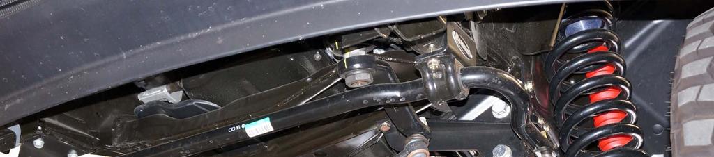
 Remove the sway bar mounts at the frame. See Illustration 1. COIL SPRING & SHOCK REMOVAL Illustration 3 2) Disconnect the track bar from the frame bracket. See Illustration 1. 3) Raise the front of the vehicle and support the frame with jack stands.")
 Support the front axle with two floor jacks, one under each coil spring. 2) Mark position of alignment cam bolts on radius arms. See Illustration 2.")
8 VEHICLE PREPARATION & SWAY BAR REMOVAL 1) Park the vehicle on a level surface. Set the parking brake and chock the rear wheels. Measure and record the distance from the center of each wheel to the top of the fender opening. See Illustration 3 Record these measurements in the space provided below. 4) Mark the pitman arm and steering gear box shaft for installation reference. Remove the nut and washer from the pitman arm. 5) Using a pitman arm puller, remove the pitman arm. 6) Remove the sway bar mounts at the frame. See Illustration 1. COIL SPRING & SHOCK REMOVAL Illustration 3 2) Disconnect the track bar from the frame bracket. See Illustration 1. 3) Raise the front of the vehicle and support the frame with jack stands. Remove the front wheels and set them aside. ATTENTION: Leave 4 inches between radius arm frame mount and jack stand to allow clearance for radius arm drop brackets. See Illustration 4. 1) Support the front axle with two floor jacks, one under each coil spring. 2) Mark position of alignment cam bolts on radius arms. See Illustration 2. 3) Remove the mounting bolts holding the front brake hoses brackets to axle. There are 2 brackets on each side. See Illustration 5. 4 Illustration 5 4) Remove clip attaching wire to solenoid on passenger side of axle. See Illustration 6. Illustration 4 PITMAN ARM & SWAY BAR REMOVAL 1) Mark and measure the position of the drag link adjusting barrel jam nuts, then loosen the jam nuts. See Illustration 1. 2) Remove the drag link ball stud nut at the pitman arm. 3) Using a pitman arm puller, separate the drag link from the pitman arm. See Illustration 1. NOTE: Make sure puller jaws seat on pitman arm, not the boot retainer of the ball stud. Illustration 6 8
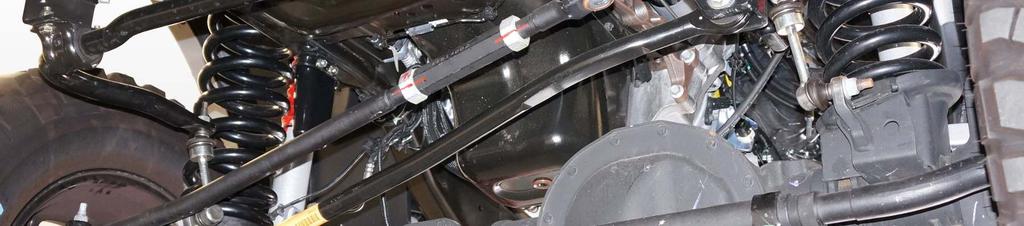
 Working on the passenger side first, install welded spacer RS420106 from the outside through the slot in the frame and radius arm mount.")


 Radius Arm Drop Brackets RS176726, RS176727 Hardware from Sub Assy RS860755 1) Support the jack point")

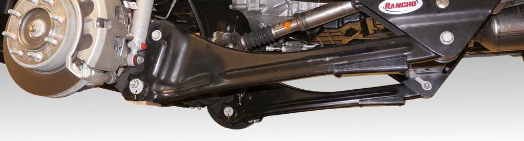
9 5) Disconnect the front differential vent hose clip at driver side shock/spring mount tower, and plastic clip on inside of frame rail. See Illustration 2 and Illustration 7. Vent Hose Clip 2) Working on the passenger side first, install welded spacer RS from the outside through the slot in the frame and radius arm mount. Slide larger diameter 3/16 thick washer RS over welded spacer where it protrudes from the inside of the frame rail. A small piece of tape or super-glue can be used to help hold the washer during installation. See Illustration 9. RS Illustration 7 6) Remove the front shock absorbers starting at the axle. 7) Carefully lower the axle enough to relieve the tension on the coil springs and remove coils. FRONT WARNING: Do not allow the axle to hang by any hoses or ABS cables. You could damage the hoses or ABS cables, without this damage being visible to you, resulting in sudden and unexpected failure of a hose or ABS system, and an accident. RS RADIUS ARM DROP BRACKET INSTALLATION Box RS66452B-3 (Box 3 of 5) Radius Arm Drop Brackets RS176726, RS Hardware from Sub Assy RS ) Support the jack point of both radius arms with jack stands. Remove the radius arm mounting bolts at the frame and lower the radius arms out of the frame brackets. See Illustration 8. CAUTION: Always support at least one radius arm with a jack stand to keep the axle from rotating downward. Check driveshaft slip joint boot to prevent tearing. FRONT Slot Illustration 9 3) Loosely Install 10mm washer (under head of bolt), 220mm long bolt, 7.37 long spacer (RS420105) and nylock nut on passenger side radius arm drop bracket RS See Illustration 10. RS No Washer M10X220 RS Illustration 8 9 Illustration 10
 and hardware will need to go through slot and out the top of the frame. See Illustration 9 and Illustration 10.")

10 4) Install passenger side radius arm drop bracket RS over OE radius arm bracket and previously installed welded spacer and washer in frame long spacer (RS420105) and hardware will need to go through slot and out the top of the frame. See Illustration 9 and Illustration mm 2 3 5) Loosely install 12mm hardware through slot in radius arm drop bracket. Loosely install supplied 18mm hardware and 3.24 long spacer (RS420104) in OE radius arm mounting location. See Illustration 11. RS RS M10 Hardware RS RS RS RS M12 Hardware RS Illustration 12 M18 Hardware OE Hardware RS ) Loosely install 10mm hardware from kit RS in locations 1 and 2. See Illustration 12 and Illustration 14. NOTE: If the holes in the frame and RS do not line up in position 1, drill out the hole at with a 13/32 drill. On some vehicles it may be necessary to use two washers behind the bolt head at position 2. Illustration 11 6) Hold 10mm X 220mm bolt to prevent it and 7.37 long spacer from falling out or into frame rail. Remove 10mm nut. Install smaller diameter 3/16 thick washer (RS420108) and 10mm flat washer. Re-install 10mm nut. 7) Torque hardware in following order: 10mm hardware to 35 ft. lbs., 12mm hardware to 75 ft. lbs., 18mm hardware to 240 ft. lbs. 8) Repeat steps 2-7 on driver side with radius arm drop bracket RS ) Lift the radius arms into the drop bracket. Install the original bolts and nuts. Do not tighten until the vehicle is at normal ride height. See Page 14 TRACK BAR BRACKET INSTALLATION Box RS66452B-2 (Box 2 of 5) Front Track Bar Bracket RS176725B Hardware from Sub Assy RS ) Place track bar bracket RS176725B over the OE track bar mount. Loosely install supplied 18mm hardware and spacer RS at OE track bar mounting location to hold the bracket in place. See Illustration 12. 3) Using the hole in the track bar bracket as a guide (location 3), enlarge the slot in the vehicle cross member to 13/32. 4) Insert flag nut RS through the hole in top of the cross member and attach the track bar bracket to the cross member with 10mm hardware. Torque to 30 ft. lbs. 5) Torque remaining 10mm hardware to 45 ft. lbs. in the order numbered in See Illustration 12. Do not tighten 18mm hardware. BUMP STOP BRACKET INSTALLATION Box RS66452B-2 (Box 2 of 5) Hardware from Sub Assy RS ) Remove the bump stops from the frame brackets by hitting from the side with a hammer. 2) If necessary, enlarge holes in frame brackets and frame to 5/16. See Illustration 13. 3) To ease installation, tap holes to 3/8-16 NOTE: If no tap is available, pre-install supplied 3/8 self-tapping bolts using oil to form threads. Clean bolts and holes of oil. 4) Install bump stop spacer RS with flat facing out using supplied 3/8 self-tapping bolt. Use red LocTite. Torque to 25 ft. lbs. See Illustration 13 and Illustration 14. 5) Attach bump stop RS to spacer RS with the M8 hardware from kit RS Use red LocTite Tighten bolts to 15 ft. lbs. See Illustration 13 and Illustration
 Spring Locator RS176741 Hardware from Sub Assy")
 1) Remove the upper spring isolators and cut off")
 Mark, center punch, and drill a ¼ hole on the outside of the upper spring mount dimple, ¼")


11 COIL SPRING & SHOCK ABSORBER INSTALLATION Box RS66452B-1 (Box 1 of 5) Front Coil Springs RS831B 5/16 Holes Box RS66452B-2 (Box 2 of 5) Spring Locator RS Hardware from Sub Assy RS RS17764 New Rancho front shock absorbers NOTE: Both springs will have to be rotated 90 clockwise (when looking from the top) 1) Remove the upper spring isolators and cut off locating tabs. See Illustration 15. 2) Mark, center punch, and drill a ¼ hole on the outside of the upper spring mount dimple, ¼ from the lower edge of the dimple. De-bur inside of hole with a round or half-round file. See Illustration 16. RS /4 Illustration 13 1 RS17764 RS17765 Illustration 16 3) Install spring locator RS into hole of upper spring mount. While holding locator up against spring mount drill a ¼ hole through locator using previously drilled ¼ hole as a guide. RS Illustration 14 1/4 Hardware Cut RS Illustration Illustration 17
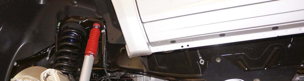
 Re-install the passenger side upper spring isolator with the coil stop to the rear of the vehicle. See Illustration 18.")
 Re-attach the OE brake line brackets to the axle spring mount using the OE hardware. 14) Install brake line brackets RS176728 to the axle radius arm mount using the OE hardware.")
 Carefully re-shape brake line and attach the OE brake line bracket to RS176728 using ¼ hardware from kit RS860754. See Illustration 20.")

12 4) Install spring locator RS using ¼ hardware supplied it kit RS Install with button head out, and washer under nut. See Illustration 17. 5) Re-install the passenger side upper spring isolator with the coil stop to the rear of the vehicle. See Illustration 18. Coil Pigtail FRONT 12) Carefully raise the axle enough to install the shocks on the lower mounts. Attach with the OE hardware and torque to 120 ft. lbs. 13) Re-attach the OE brake line brackets to the axle spring mount using the OE hardware. 14) Install brake line brackets RS to the axle radius arm mount using the OE hardware. NOTE: Use loctite and take care not to strip out self-tapping screws used on brake line mounts. 15) Carefully re-shape brake line and attach the OE brake line bracket to RS using ¼ hardware from kit RS See Illustration 20. RS831B Passenger side coil spring after rotating 90 from OE position Illustration 18 6) Place the passenger side spring RS831B in the lower and upper mounts. The top of the spring will have a small flat section on the edge. Align the upper pigtail to the isolator See Illustration 18. 7) Raise the passenger side of the axle just enough to keep the spring from falling out. 8) Re-install the driver side upper spring isolator with the coil stop to the outside of the vehicle. See Illustration 19. RS Illustration 20 16) Re-rout the axle vent hose under the frame rail and attach metal clip at OE location on shock/spring mount. See Illustration 21 FRONT Coil Pigtail RS831B Axle Vent Hose Driver side coil spring after rotating 90 from OE position Illustration 19 9) Place the driver side spring RS831B in the lower and upper mounts. The top of the spring will have a small flat section on the edge. Align the upper pigtail to the isolator. See Illustration ) Raise the driver side of the axle just enough to keep the spring from falling out. 11) Install new Rancho shocks in the upper shock mounts. 12 Illustration 21

 Rotate the adjusting barrel down in the front 5 ½ turns to make drag link assembly shorter. Tighten jam nuts.")

13 PITMAN ARM AND DRAG LINK INSTALLATION Box RS66452B-2 (Box 2 of 5) Pitman arm RS77982 WARNING PROPER INSTALLATION OF THE PITMAN ARM IS CRUCIAL 1. Use a calibrated torque wrench. Follow OEM torque requirement of 225 ft-lbs. 2. Use of Red LocTite 271 or equivalent is required. 3. Recheck the torque setting within 30 days. 4. Do this procedure annually or after every off-road use. FAILURE TO FOLLOW ABOVE PROCEDURES WILL VOID ALL WARRANTIES. 4) Attach the drag link to the pitman arm with the OE nut. Torque nut to 65 ft. lbs. 5) Rotate the adjusting barrel down in the front 5 ½ turns to make drag link assembly shorter. Tighten jam nuts. SWAY BAR DROP BRACKET INSTALLATION Box RS66452B-2 (Box 2 of 5) Front Sway Bar Drop Bracket RS17729B, RS176730B Hardware from Sub Assy RS ) Attach left sway bar drop bracket RS176729B to the driver side the frame with OE hardware. The Rancho logo will face out, and the sway bar will be offset to the front of the vehicle. See Illustration 24. RS176729B 1) Using the reference marks on the OE pitman arm as a guide, attach new pitman arm RS77982 to the steering shaft. Install the OE lock washer and nut with Locktite. Tighten the nut to 225 ft. lbs.. See Illustration 23. 2) Remove tie rod end from the drag link adjusting barrel and trim off tab flush with the threads See Illustration 22. Cut Illustration 22 3) Re-install the tie rod end onto the adjusting barrel and adjust to the previous marks and measurement. Rotate the tie rod end out a half turn so the ball joint threads point up. See Illustration 23. RS77982 FRONT Illustration 24 2) Attach right sway bar drop bracket RS176730B to the passenger side the frame with OE hardware. The Rancho logo will face out, and the sway bar will be offset to the front of the vehicle. See Illustration 24. 3) Attach the sway bar to the drop brackets with 10mm hardware from kit RS Torque hardware to 40 ft. lbs. LOWER VEHICLE RS176730B 1) Install the front wheels and lower the vehicle to the ground. Tighten lug nuts to 140 ft. lbs. Note: If installing aftermarket wheels, remove rotor retainer clips from wheel studs to allow wheels to sit flush against rotor. See Illustration 1. Illustration ) Attach track bar to bracket RS with 18mm hardware from kit RS Tighten both 18mm track bar and bracket bolts to 220 ft. lbs. Note: If track bar does not line up with bracket, have an assistant slowly turn steering wheel until holes align. 3) Tighten radius arm bolts at drop bracket to 220 ft. lbs.
14 14
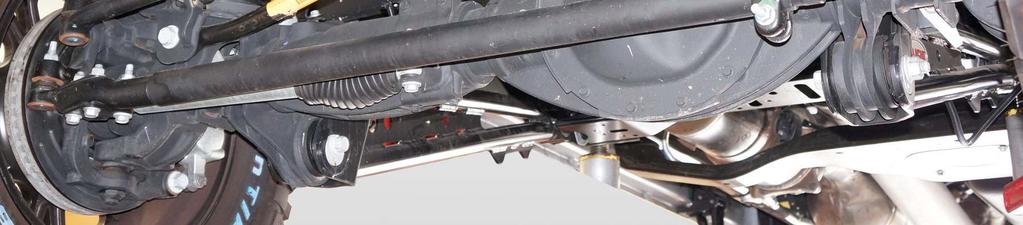
 Remove axle vent line clip from the rear track bar axle mounting bracket. See Illustration 25.")
 Raise the rear of the vehicle and support the frame with jack stands. Remove rear wheels.")
 Mark location of lower coil spring isolators spring stop on lower coil mount and remove isolator from coil mount. See Illustration 26.")

15 REAR SUSPENSION Track Bar Sway Bar Vent Hose Clip Illustration 25 SHOCK ABSORBER & COIL SPRING REMOVAL 1) Chock front wheels. 2) Remove axle vent line clip from the rear track bar axle mounting bracket. See Illustration 25. 3) Remove the bolt and nut holding the track bar to the rear axle. See Illustration 25. 4) Raise the rear of the vehicle and support the frame with jack stands. Remove rear wheels. 5) Support the rear axle assembly with a floor jack. 6) Remove sway bar end links from frame brackets. See Illustration 25. 7) Mark location of lower coil spring isolators spring stop on lower coil mount and remove isolator from coil mount. See Illustration 26. 8) Remove the upper and lower shock mounting bolts. Remove shock absorber. 9) Carefully lower the rear axle. Do not allow the axle to hang by any hoses or ABS cables. Illustration 26 WARNING: Do not allow the axle to hang by any hoses or ABS cables. You could damage the hoses or ABS cables, without this damage being visible to you, resulting in sudden and unexpected failure of a hose or ABS system, and an accident. 10) Remove both coil springs and upper insulators from vehicle. 15
 Place track bar bracket RS176731 over OE track bar axle bracket.")
 Loosely attach track bar bracket RS176731 at bottom with 10mm bolt and flag nut RS176735. Use extra supplied M10 washers to fill gap between OE bracket and RS176731 if needed. See Illustration 27.")

 Repeat steps 4 & 5 for passenger side coil spring spacers RS176734 using only 30mm long 10mm hardware from kit RS860759. 6) Tighten lower 10mm track bar bracket hardware to 35 ft. lbs.")
16 TRACK BAR BRACKET & COIL SPRING SPACER INSTALLATION Box RS66452B-4 (Box 4 of 5) Rear Track Bar Bracket RS176731B Hardware from Sub Assy RS Box RS66452B-5 (Box 5 of 5) Rear Coil Spacers RS Hardware from Sub Assy RS New Rancho Rear Shock Absorbers 1) Place track bar bracket RS over OE track bar axle bracket. Install OE track bar bolt, OE flag nut and spacer RS from kit RS at original track bar mounting location. Do not tighten hardware at this time. 2) Loosely attach track bar bracket RS at bottom with 10mm bolt and flag nut RS Use extra supplied M10 washers to fill gap between OE bracket and RS if needed. See Illustration 27. RS RS ) Place coil spring spacers RS onto the lower coil spring mount with flat side down. Align the holes in the spacer with holes in the coil mount and attach spacer and track bar bracket to OE coil mount with 35mm long 10mm hardware from kit RS860758, and 30mm long 10mm hardware from kit RS through the forward hole in spacer. 4) Place lower isolator on spacer, aligning with previously made mark. 5) Repeat steps 4 & 5 for passenger side coil spring spacers RS using only 30mm long 10mm hardware from kit RS ) Tighten lower 10mm track bar bracket hardware to 35 ft. lbs. Tighten remaining 10mm track bar and coil spacer hardware to 45 ft. lbs. 7) Using hole in track bar bracket RS as a guide, drill a 13/32 hole through the OE track bar mount. Attach using remaining 10mm hardware from kit RS Tighten to 45 ft. lbs. See Illustration 28. 8) Place original insulator to top of coil, then raise the axle guiding the springs into the frame pockets. 9) Attach new Rancho shock absorbers to the upper and lower mounts. Torque to 120 ft. lbs. SWAY BAR ENDLINK DROP BRACKET INSTALLATION Box RS66452B-4 (Box 4 of 5) Rear Sway Bar End Link Drop Bracket RS OE RS RS M10x35mm Hardware from Sub Assy RS ) Place sway bar end link drop bracket RS over OE end link mounting bracket. See Illustration 29. M10X35mm Illustration 27 M10x30mm RS RS M10x35mm RS Drill 13/32 M10x35mm Illustration 28 Illustration 29 2) Install with hardware from kit RS Use 8mm hardware in top hole, and 12mm hardware in middle hole. Torque 8mm hardware to 20 ft. lbs., and 12mm hardware to 55 ft. lbs. 16
 Rear Bump Stop Spacers RS176732 Hardware from Sub Assy RS860756 1) Remove bump stops from frame.")
17 3) Attach sway bar end link to drop bracket RS with OE hardware. Torque to 75 ft. lbs. BUMP STOP DROP BRACKET INSTALLATION Box RS66452B-4 (Box 4 of 5) Rear Bump Stop Spacers RS Hardware from Sub Assy RS ) Remove bump stops from frame. 2) Attach bump stop spacer RS to frame using OE hardware. See Torque hardware to 40 ft. lbs. NOTE: On passenger side spacer, install and snug rear bolt first with spacer rotated to allow easier access to bolt. 3) Attach bump stop to spacers RS using 10mm hardware supplied in kit RS Torque hardware to 40 ft. lbs. Illustration 29. E-BRAKE DROP BRACKET INSTALLATION Box RS66452B-4 (Box 4 of 5) E-Brake Drop Bracket RS Hardware from Sub Assy RS ) Attach e-brake drop bracket RS to OE e-brake hanger using 8mm hardware from kit RS ) Attach e-brake drop bracket and hanger to frame using OE hardware. See Illustration 30. LOWER VEHICLE 1) Install rear wheels and lower vehicle to ground. Tighten lug nuts to 140 ft. lbs. Note: If installing aftermarket wheels, remove rotor retainer clips from wheel studs to allow wheels to sit flush against rotor. See Illustration 1. 2) Attach track bar to Rancho track bar bracket RS using 14mm hardware supplied in kit RS Torque both upper and lower 14mm track bar and bracket bolts to 120 ft. lbs. CHECKS & ADJUSTMENTS 1) Turn the front wheels completely left then right. Verify adequate tire, wheel, and brake hose clearance. Inspect steering and suspension for tightness and proper operation. 2) With the suspension at maximum extension (full droop), inspect and rotate all axles and drive shafts. Check for binding and proper slip yoke insertion. The slip yoke should be inserted a minimum of one inch into the transfer case and/or transmission. 3) Ensure that the vehicle brake system operates correctly. If new brake hoses were installed, verify that each hose allows for full suspension movement. 4) Readjust headlamps. 5) Center steering wheel. Have vehicle Aligned at a certified alignment facility. 6) Measure and record the distance from the center of each wheel to the top of the fender opening. See Illustration 31. Record these measurements in the space provided below. RS Illustration 31 Illustration 30 17


18 NOTE: Vehicles equipped with two piece rear driveshaft may require and additional drive shaft carrier bearing spacer kit. If you experience drive-line vibration after installing this kit on a vehicle with a two piece rear driveshaft, please contact Rancho Technical Support at and ask for: RS RS RS6609 Carrier Bearing Spacer Sub Assy, Carrier Bearing Spacer Hdwr. Please retain this publication for future reference. See Important Note Q. Rancho Technical Department at
INSTALLATION INSTRUCTIONS
 89451 Rev B INSTALLATION INSTRUCTIONS For Rancho Suspension Systems: RS66451R9 2.5 Leveling Kit - DIESEL MODELS ONLY 2014 Dodge Ram 2500 4WD FMVSS 126 Certified Fits OE rims and spare Fits up to: BFG KM2
INSTALLATION INSTRUCTIONS
 INSTALLATION INSTRUCTIONS For Rancho Suspension System RS6524B: 2011-2013 Ford F250, F350 Super Duty 4x4 DIESEL ONLY (Single Rear Wheels Only With or Without Auxiliary Spring). (WILL NOT WORK ON GAS ENGINES
These instructions should remain in the vehicle glove box for future reference.
 INSTALLATION INSTRUCTION 89118 Rev B Rancho Suspension System RS66118BR5 and RS66118BR9 2 Progressive Sport System Fits 2017-2007 Jeep Wrangler JK 2-Door This suspension system was developed using 255/80R17
INSTALLATION INSTRUCTION 88578
 INSTALLATION INSTRUCTION 88578 For Rancho Suspension System RS6579B: 4WD Dodge 1500 & 2500 READ ALL INSTRUCTIONS THOROUGHLY FROM START TO FINISH BEFORE BEGINNING INSTALLATION Rev E IMPORTANT NOTES! WARNING:
INSTALLATION INSTRUCTIONS
 INSTALLATION INSTRUCTIONS 89552 Rev A For Rancho Suspension System RS66552B: 2017-2011 Ford F250 / F350 Super Duty 4x4* *F350 requires additional rear kit RS886503 or RS886502 to be purchased separately.
INSTALLATION INSTRUCTION 89450
 INSTALLATION INSTRUCTION 89450 Rancho Suspension System RS66450R7: Fits 2003 2013 4WD Dodge Ram 2500 / 3500 DIESEL MODELS ONLY. READ ALL INSTRUCTIONS THOROUGHLY FROM START TO FINISH BEFORE BEGINNING INSTALLATION
INSTALLATION INSTRUCTION Rev A
 INSTALLATION INSTRUCTION 88587 Rev A FOR RANCHO SUSPENSION SYSTEM RS6587B: 2009 DODGE RAM 1500 READ ALL INSTRUCTIONS THOROUGHLY FROM START TO FINISH BEFORE BEGINNING INSTALLATION IMPORTANT NOTES! WARNING:
Suspension System RS6507B (Rubicon models require end link kit RS6753B for a complete installation)
") 88507 Rev G Suspension System RS6507B (Rubicon models require end link kit RS6753B for a complete installation) Jeep Wrangler (JK) 88507 Rev G READ ALL INSTRUCTIONS THOROUGHLY FROM START TO FINISH BEFORE
88507 Rev G Suspension System RS6507B (Rubicon models require end link kit RS6753B for a complete installation) Jeep Wrangler (JK) 88507 Rev G READ ALL INSTRUCTIONS THOROUGHLY FROM START TO FINISH BEFORE
INSTALLATION INSTRUCTION 89400
 INSTALLATION INSTRUCTION 89400 FOR RANCHO SUSPENSION SYSTEM RS66400B: 2012 RAM 1500 4WD. READ ALL INSTRUCTIONS THOROUGHLY FROM START TO FINISH BEFORE BEGINNING INSTALLATION Rev B IMPORTANT NOTES! WARNING:
INSTALLATION INSTRUCTION 88094
 INSTALLATION INSTRUCTION 88094 FOR RANCHO SUSPENSION SYSTEM RS6594B 4WD & 2WD NISSAN TITAN READ ALL INSTRUCTIONS THOROUGHLY FROM START TO FINISH BEFORE BEGINNING INSTALLATION Rev D IMPORTANT NOTES! WARNING:
INSTALLATION INSTRUCTION 89455
 INSTALLATION INSTRUCTION 89455 Rev A Rancho Suspension Systems RS66455B 2013 2009 4WD Dodge RAM 2500 READ ALL INSTRUCTIONS THOROUGHLY FROM START TO FINISH BEFORE BEGINNING INSTALLATION WARNING Carefully
INSTALLATION INSTRUCTION 88581
 INSTALLATION INSTRUCTION 88581 FOR RANCHO SUSPENSION SYSTEM RS6581B: DODGE RAM READ ALL INSTRUCTIONS THOROUGHLY FROM START TO FINISH BEFORE BEGINNING INSTALLATION Rev C IMPORTANT NOTES! WARNING: This suspension
INSTALLATION INSTRUCTIONS 88518
 INSTALLATION INSTRUCTIONS 88518 For Rancho Suspension Systems RS6518: 2009 FORD F-150 4WD READ ALL INSTRUCTIONS THOROUGHLY FROM START TO FINISH BEFORE BEGINNING INSTALLATION Rev A IMPORTANT NOTES! WARNING:
INSTALLATION INSTRUCTION Rev A
 INSTALLATION INSTRUCTION RS82100 Rev A Rancho High-Steer Knuckle RS62100 Fits 2016-2007 Jeep Wrangler JK Left and Right Hand Drive Models Requires use of flipped drag link, and 3 or higher lift with a
Jeep Wrangler (JK)
") 89109 Rev B Suspension Systems RS66109BR5 and RS66109BR9 2007 2013 Jeep Wrangler 4 Door Sport and Rubicon Models (2 SPORT SYSTEM) Jeep Wrangler (JK) 2007-2013 89109 Rev B READ ALL INSTRUCTIONS THOROUGHLY
89109 Rev B Suspension Systems RS66109BR5 and RS66109BR9 2007 2013 Jeep Wrangler 4 Door Sport and Rubicon Models (2 SPORT SYSTEM) Jeep Wrangler (JK) 2007-2013 89109 Rev B READ ALL INSTRUCTIONS THOROUGHLY
INSTALLATION INSTRUCTIONS
 88553 Rev A INSTALLATION INSTRUCTIONS For Rancho Suspension System RS66553B: 2017-2011 Ford F250 / F350 Super Duty 4x4 2.5 Leveling Kit (Available in black only. Component in illustrations may be red for
INSTALLATION INSTRUCTION 88088
 INSTALLATION INSTRUCTION 88088 For Rancho Suspension Systems RS6588 & RS6589: FORD F-150 READ ALL INSTRUCTIONS THOROUGHLY FROM START TO FINISH BEFORE BEGINNING INSTALLATION Rev B IMPORTANT NOTES! WARNING:
INSTALLATION INSTRUCTION Rev B Rancho Upper Control Arm Upgrade Kit RS64903
 INSTALLATION INSTRUCTION RS89903-1 Rev B Rancho Upper Control Arm Upgrade Kit RS64903 Fits 2016-2003 Toyota 4Runner 4WD Excludes TRD PRO Models READ ALL INSTRUCTIONS THOROUGHLY FROM START TO FINISH BEFORE
INSTALLATION INSTRUCTIONS 89551
 INSTALLATION INSTRUCTIONS 89551 For Rancho Suspension System RS66551B: Ford F250, F350 Super Duty 4x4 DIESEL ONLY (Single Rear Wheels Only With or Without Auxiliary Spring). (WILL NOT WORK ON GAS ENGINES
Suspension System RS6525 (B)
") 88525 Rev A Suspension System RS6525 (B) Requires coil spring kit RS80116 (B) or RS80118 (B) for a complete installation Ford Super Duty READ ALL INSTRUCTIONS THOROUGHLY FROM START TO FINISH BEFORE BEGINNING
88525 Rev A Suspension System RS6525 (B) Requires coil spring kit RS80116 (B) or RS80118 (B) for a complete installation Ford Super Duty READ ALL INSTRUCTIONS THOROUGHLY FROM START TO FINISH BEFORE BEGINNING
INSTALLATION INSTRUCTION Rancho 2 Rubicon Progressive Coil System
 INSTALLATION INSTRUCTION 89122 Rancho 2 Rubicon Progressive Coil System RS66122BR5 Includes RS5000X Shocks RS66122BR9 Includes RS9000XL Shocks Fits 2018 Jeep Wrangler JLU 4-Door Rubicon Models Rev D This
INSTALLATION INSTRUCTIONS 88511
 INSTALLATION INSTRUCTIONS 88511 For Suspension System RS6511: Ford Super Duty Requires coil spring kit RS80117 or RS80119 for a complete installation READ ALL INSTRUCTIONS THOROUGHLY FROM START TO FINISH
Suspension System RS6509B
 88509 Rev H Requires the following for a complete installation: Quick disconnect end link kit RS6756B or solid end link kit RS6753B (for the Rubicon) Rancho exhaust kit RS720001 or RS720002 (or equivalent)
Jeep Wrangler (JK) Present
 Present") Suspension System RS66110B (3 SPORT SYSTEM w/ Progressive Coil Springs Front & Rear) 2012 NEWER JEEP MODELS EQUIPPED WITH 3.6L V6 ENGINE NEED EXHAUST MODIFICATION KIT RS720003. OR REPLACEMENT FRONT DRIVESHAFT
Suspension System RS66110B (3 SPORT SYSTEM w/ Progressive Coil Springs Front & Rear) 2012 NEWER JEEP MODELS EQUIPPED WITH 3.6L V6 ENGINE NEED EXHAUST MODIFICATION KIT RS720003. OR REPLACEMENT FRONT DRIVESHAFT
Suspension System RS6582B
 Suspension System RS6582B Tahoe/Yukon READ ALL INSTRUCTIONS THOROUGHLY FROM START TO FINISH BEFORE BEGINNING INSTALLATION IMPORTANT NOTES! WARNING: This suspension system will enhance the off-road performance
Suspension System RS66102B
 890 Rev A Suspension System RS660B ( SPORT SYSTEM) 0 JEEP MODELS EQUIPED WITH 3.6L V6 ENGINE NEED EXHAUST MODIFYCATION KIT RS70003. OR REPLACEMENT FRONT DRIVESHAFT (DRIVESHAFT / EXHAUST CLERANCE ISSUE).
INSTALLATION INSTRUCTIONS
 INSTALLATION INSTRUCTIONS 89401 Rev D For Rancho Suspension System RS66401B: 2013-2016 RAM 1500 4WD ATTENTION: DOES NOT FIT V6 DIESEL OR VEHICLES EQUIPPED WITH AIR RIDE. Fits OE 17 and up rims ONLY WITH
INSTALLATION INSTRUCTION 88073
 INSTALLATION INSTRUCTION 88073 Rev C FOR RANCHO SUSPENSION SYSTEMS RS6572 & RS6573: DODGE RAM READ ALL INSTRUCTIONS THOROUGHLY FROM START TO FINISH BEFORE BEGINNING INSTALLATION IMPORTANT NOTES! WARNING:
INSTALLATION INSTRUCTION 88092
 INSTALLATION INSTRUCTION 88092 FOR RANCHO SUSPENSION SYSTEM RS6592: NISSAN XTERRA & 2WD FRONTIER READ ALL INSTRUCTIONS THOROUGHLY FROM START TO FINISH BEFORE BEGINNING INSTALLATION Rev C IMPORTANT NOTES!
Suspension Upgrade System RS66152 (Upper Adjustable Control Arms)
") 89152 Rev B Suspension Upgrade System RS66152 (Upper Adjustable Control Arms) Fits 1997-2006 Jeep Wrangler (TJ / LJ). 89152 Rev B READ ALL INSTRUCTIONS THOROUGHLY FROM START TO FINISH BEFORE BEGINNING
89152 Rev B Suspension Upgrade System RS66152 (Upper Adjustable Control Arms) Fits 1997-2006 Jeep Wrangler (TJ / LJ). 89152 Rev B READ ALL INSTRUCTIONS THOROUGHLY FROM START TO FINISH BEFORE BEGINNING
INSTALLATION INSTRUCTION 88146
 INSTALLATION INSTRUCTION 88146 Rev H FOR RANCHO SUSPENSION SYSTEM RS6547: 4WD SUBURBAN/YUKON XL, 4WD TAHOE/YUKON, & 4WD AVALANCHE READ ALL INSTRUCTIONS THOROUGHLY FROM START TO FINISH BEFORE BEGINNING
INSTALLATION INSTRUCTION Rev B Rancho Suspension System RS66114B
 INSTALLATION INSTRUCTION 89114 Rev B Rancho Suspension System RS66114B 4 Crawler Progressive Coil Short Arm System Black Fits 2017-2007 Jeep Wrangler JK 2012 - Newer models equipped with 3.6L V6 engine
INSTALLATION INSTRUCTION 88148
 INSTALLATION INSTRUCTION 88148 Rev C For Rancho Suspension Systems RS6548, RS6549 & RS6550: GM 2500HD, 2500, and 1500HD Trucks READ ALL INSTRUCTIONS THOROUGHLY FROM START TO FINISH BEFORE BEGINNING INSTALLATION
Jeep Wrangler (JK) Present
 Present") 89107 Rev H Suspension System RS66107 / RS66107B (3 TRAIL SYSTEM) 2012 NEWER JEEP MODELS EQUIPPED WITH 3.6L V6 ENGINE NEED EXHAUST MODIFICATION KIT RS720003. OR REPLACEMENT FRONT DRIVESHAFT (DRIVESHAFT
89107 Rev H Suspension System RS66107 / RS66107B (3 TRAIL SYSTEM) 2012 NEWER JEEP MODELS EQUIPPED WITH 3.6L V6 ENGINE NEED EXHAUST MODIFICATION KIT RS720003. OR REPLACEMENT FRONT DRIVESHAFT (DRIVESHAFT
Suspension System RS66107 / RS66107B
 89107 Rev D Suspension System RS66107 / RS66107B (3 TRAIL SYSTEM) 2012 JEEP MODELS EQUIPPED WITH 3.6L V6 ENGINE NEED EXHAUST MODIFICATION KIT RS720003. OR REPLACEMENT FRONT DRIVESHAFT (DRIVESHAFT / EXHAUST
INSTALLATION INSTRUCTION 88581
 INSTALLATION INSTRUCTION 88581 FOR RANCHO SUSPENSION SYSTEM RS6581B: DODGE RAM READ ALL INSTRUCTIONS THOROUGHLY FROM START TO FINISH BEFORE BEGINNING INSTALLATION Rev D IMPORTANT NOTES! WARNING: This suspension
INSTALLATION INSTRUCTION 88051
 INSTALLATION INSTRUCTION 88051 For Rancho Suspension System RS6551: Chevrolet 2500 Suburban & 2500 Avalanche READ ALL INSTRUCTIONS THOROUGHLY FROM START TO FINISH BEFORE BEGINNING INSTALLATION Rev C IMPORTANT
INSTALLATION INSTRUCTIONS
 INSTALLATION INSTRUCTIONS 89500 Rev G For Rancho Suspension Systems: RS66500B 4½ Lift 2016-2015 Ford F150 4WD FMVSS 126 Certified Requires Rancho shock absorber or strut spacers for installation. Replacement
Suspension System RS66104 & RS66104B (4 Crawler System)
") 89104 Rev B Suspension System RS66104 & RS66104B (4 Crawler System) 2012 JEEP MODELS EQUIPED WITH 3.6L V6 ENGINE NEED EXHAUST MODIFICATION KIT RS720003. OR REPLACEMENT FRONT DRIVESHAFT (DRIVESHAFT / EXHAUST
89104 Rev B Suspension System RS66104 & RS66104B (4 Crawler System) 2012 JEEP MODELS EQUIPED WITH 3.6L V6 ENGINE NEED EXHAUST MODIFICATION KIT RS720003. OR REPLACEMENT FRONT DRIVESHAFT (DRIVESHAFT / EXHAUST
INSTALLATION INSTRUCTIONS 88029
 INSTALLATION INSTRUCTIONS 88029 FOR SUSPENSION SYSTEMS RS6503: JEEP WRANGLER (TJ) READ ALL INSTRUCTIONS THOROUGHLY FROM START TO FINISH BEFORE BEGINNING INSTALLATION REV F IMPORTANT NOTES! WARNING: This
INSTALLATION INSTRUCTIONS
 INSTALLATION INSTRUCTIONS 89301 Rev D For Rancho Suspension Systems: RS66301B - Fits vehicles equipped with factory steel control arms RS66302B - Fits vehicles equipped with factory aluminum control arms
Suspension System RS66105
 89105 Rev D Requires the following for a complete installation: OE frame bracket removal Transmission Crossmember Kit (see below). 2012 and later models equipped with 3.6l V6 engine need exhaust modification
NOT COMPATIBLE WITH 6.2L
 INSTALLATION INSTRUCTION 89308 Rev D Rancho Suspension Systems: RS66308B Fits vehicles equipped with factory forged steel upper control arm RS66309B Fits vehicles equipped with factory aluminum or stamped
Stamped steel upper control arms NOT COMPATIBLE with OE wheels. See page 4 NOT COMPATIBLE WITH 6.2L Engine, or Z95 Magnetic Ride Control
 INSTALLATION INSTRUCTION 89308 Rev C Rancho Suspension Systems: RS66308B Fits vehicles equipped with factory forged steel upper control arm RS66309B Fits vehicles equipped with factory aluminum or stamped
INSTALLATION INSTRUCTION 89308
 INSTALLATION INSTRUCTION 89308 Rancho Suspension Systems: RS66308B Fits vehicles equipped with factory forged steel upper control arm RS66309B Fits vehicles equipped with factory aluminum or stamped steel
INSTALLATION INSTRUCTIONS
 INSTALLATION INSTRUCTIONS FOR RANCHO SPORT KIT SUSPENSION SYSTEMS RS6501: JEEP WRANGLER (TJ) READ ALL INSTRUCTIONS THOROUGHLY FROM START TO FINISH BEFORE BEGINNING INSTALLATION IMPORTANT NOTES! WARNING:
Suspension System RS6509B
 88509 Rev D Requires the following for a complete installation: Quick disconnect end link kit RS6756B or solid end link kit RS6753B (for the Rubicon) Rancho exhaust kit RS720001 or RS720002 (or equivalent)
INSTALLATION INSTRUCTIONS 88043
 INSTALLATION INSTRUCTIONS 88043 FOR RANCHO SUSPENSION SYSTEM RS6543: CHEVROLET K1500 READ ALL INSTRUCTIONS THOROUGHLY FROM START TO FINISH BEFORE BEGINNING INSTALLATION Rev E IMPORTANT NOTES! WARNING:
NOT COMPATIBLE WITH 6.2L
 INSTALLATION INSTRUCTION 89301 Rev H Rancho Suspension Systems: RS66301B Fits vehicles equipped with factory forged steel upper control arm RS66302B Fits vehicles equipped with factory aluminum or stamped
INSTALLATION INSTRUCTION 88554
 INSTALLATION INSTRUCTION 88554 Rev B For Rancho Non-Torsion Bar Drop Suspension System RS6554B: GM 2500HD. READ ALL INSTRUCTIONS THOROUGHLY FROM START TO FINISH BEFORE BEGINNING INSTALLATION Ultra Wheels
INSTALLATION INSTRUCTION 88045
 INSTALLATION INSTRUCTION 88045 Rev B FOR RANCHO SUSPENSION SYSTEM RS6545: CHEVROLET SILVERADO READ ALL INSTRUCTIONS THOROUGHLY FROM START TO FINISH BEFORE BEGINNING INSTALLATION IMPORTANT NOTES! WARNING:
INSTALLATION INSTRUCTIONS 88043
 INSTALLATION INSTRUCTIONS 88043 FOR SUSPENSION SYSTEM RS6543: CHEVROLET K1500 Rev B READ ALL INSTRUCTIONS THOROUGHLY FROM START TO FINISH BEFORE BEGINNING INSTALLATION IMPORTANT NOTES! A. The vehicle s
2.5" & 3.5" SUSPENSION SYSTEM JEEP JK WRANGLER 2 & 4 DOOR MODELS
 2.5" & 3.5" SUSPENSION SYSTEM 2007-2018 JEEP JK WRANGLER 2 & 4 DOOR MODELS JSPEC2352 www.jksmfg.com jks@ridefox.com 517-278-1226 RV. 100818 GETTING STARTED Read all warnings, instructions, notes and cautions
97-06 JEEP TJ/LJ LONG ARM UPGRADE KIT
 921663U00 97-06 JEEP TJ/LJ LONG ARM UPGRADE KIT Thank you for choosing Rough Country for your suspension needs. This kit is an upgrade kit only. This kit includes frame mounting points and adjustable long
INSTALLATION INSTRUCTION 88267
 INSTALLATION INSTRUCTION 88267 FOR RANCHO SUSPENSION SYSTEM RS6267: 2WD CHEVROLET SUBURBAN & TAHOE READ ALL INSTRUCTIONS THOROUGHLY FROM START TO FINISH BEFORE BEGINNING INSTALLATION Rev B IMPORTANT NOTES!
Dodge 5 Lift Kit Thank you for choosing Rough Country Suspension for your Off Road needs.
 *1368BAG4* 1368BAG4 921368200 2014-16 2500 Dodge 5 Lift Kit Thank you for choosing Rough Country Suspension for your Off Road needs. Rough Country recommends a certified technician installs this system.
»Product» Safety Warning
 D1401 Installation Instructions 2013 Ram 3500, 2014 Ram 2500 4.5" Radius Arm Suspension Lift Read and understand all instructions and warnings prior to installation of product and operation of vehicle.
INSTALLATION INSTRUCTIONS 8827
 INSTALLATION INSTRUCTIONS 8827 FOR SUSPENSION SYSTEM RS6427: CHEVEROLET K1500 READ ALL INSTRUCTIONS THOROUGHLY FROM START TO FINISH BEFORE BEGINNING INSTALLATION Rev A IMPORTANT NOTES! A. Before installing
JEEP WRANGLER (YJ) 4 LEAF SPRING KIT TM w/ Power Steering & TM w/ Manual Steering
 4 LEAF SPRING KIT TM w/ Power Steering & TM w/ Manual Steering") 400 W. Artesia Blvd. Fax: (310) 747-3912 Compton, CA 90220 Ph: (877) 695-7812 www.trailmastersuspension.com JEEP WRANGLER (YJ) 4 LEAF SPRING KIT 87-96 TM3540-20013 w/ Power Steering & TM3540-20023 w/ Manual
400 W. Artesia Blvd. Fax: (310) 747-3912 Compton, CA 90220 Ph: (877) 695-7812 www.trailmastersuspension.com JEEP WRANGLER (YJ) 4 LEAF SPRING KIT 87-96 TM3540-20013 w/ Power Steering & TM3540-20023 w/ Manual
2.5" & 3.5" SUSPENSION SYSTEM
 2.5" & 3.5" SUSPENSION SYSTEM 2007-2014 JEEP JK WRANGLER 2 & 4 DOOR MODELS JSPEC2352 www.jksmfg.com jks@sporttruckusainc.com 517-278-1226 Rv. 071814 Getting Started Read all warnings, instructions, notes
5.5 Gas & 6 Diesel Radius Arm Suspension System. Dodge Ram WD Pickup Dodge Ram WD Pickup
 Part#: 012610 5.5 Gas & 6 Diesel Radius Arm Suspension System Dodge Ram 3500 4WD Pickup 2013-17 Dodge Ram 2500 4WD Pickup 2014-17 491 W. Garfield Ave., Coldwater, MI 49036. Phone: 517-279-2135 Web: www.bds-suspension.com.
(877) MON-FRI 7AM-5PM PST OR WEBSITE: ReadyLIFT.COM **Please retain this document in your vehicle at all times**
 MON-FRI 7AM-5PM PST OR WEBSITE: ReadyLIFT.COM **Please retain this document in your vehicle at all times**") IF your ReadyLIFT product has a damaged or missing part, please contact customer service directly. For warranty issues please return to the place of installation and contact ReadyLIFT. A NEW REPLACEMENT
IF your ReadyLIFT product has a damaged or missing part, please contact customer service directly. For warranty issues please return to the place of installation and contact ReadyLIFT. A NEW REPLACEMENT
Vehicle ride height chart
 Please read Instructions thoroughly and completely before beginning installation. Installation by a certified mechanic is recommended. ReadyLIFT Suspension Inc. is NOT responsible for any damage or failure
05-07 F250 6 SUSPENSION KIT
 92159300 Stabilizer Drop Brackets Track Bar Bracket Control Arm Bracket Brake Line Drop Bracket Sway Bar Link Ext. Hardware Bags Pitman Arm 6111 Add-a-leaf 6578 3 Block and U-Bolt Kit 05-07 F250 6 SUSPENSION
'99-03 CHEVROLET/GMC IFS 4WD 6" SUSPENSION SYSTEM P/N INSTALLATION INSTRUCTIONS
 1/16/04 '99-03 CHEVROLET/GMC IFS 4WD 6" SUSPENSION SYSTEM P/N. 10-41099 INSTALLATION INSTRUCTIONS NOTE: Each Lift Kit and options to Lift Kits are packaged separately. Therefore, installation procedures
XJ CHEROKEE LIFT KIT
 92169600 84-01 6.5 XJ CHEROKEE LIFT KIT Thank you for choosing Rough Country for your suspension needs. Rough Country recommends a certified technician installs this system. In addition to these instructions,
(877) MON-FRI 7AM-5PM PST OR WEBSITE: ReadyLIFT.COM **Please retain this document in your vehicle at all times**
 MON-FRI 7AM-5PM PST OR WEBSITE: ReadyLIFT.COM **Please retain this document in your vehicle at all times**") IF your ReadyLIFT product has a damaged or missing part, please contact customer service directly. For warranty issues please return to the place of installation and contact ReadyLIFT. A NEW REPLACEMENT
IF your ReadyLIFT product has a damaged or missing part, please contact customer service directly. For warranty issues please return to the place of installation and contact ReadyLIFT. A NEW REPLACEMENT
Installation Instructions
 IF YOUR ReadyLIFT OFF ROAD SUSPENSION PRODUCT IS MISSING A PART OR HAS A DAMAGED PART, PLEASE CONTACT CUSTOMER SERVICE DIRECTLY. A NEW REPLACEMENT PART WILL BE SENT TO YOU IMMEDIATELY (800)549-4620 MON-FRI
XJ CHEROKEE LIFT KIT
 921633XN200 Thank you for choosing Rough Country for your suspension needs. 84-01 4.5 XJ CHEROKEE LIFT KIT Rough Country recommends a certified technician installs this system. In addition to these instructions,
(800) MON-FRI 7AM-5PM PST OR WEBSITE: ReadyLIFT.COM **Please retain this document in your vehicle at all times**
 MON-FRI 7AM-5PM PST OR WEBSITE: ReadyLIFT.COM **Please retain this document in your vehicle at all times**") IF YOUR ReadyLIFT PRODUCT IS MISSING A OR HAS A DAMAGED PART, PLEASE CONTACT CUSTOMER SERVICE DIRECTLY. For warranty issues please return to the place of installation and contact ReadyLIFT. A NEW REPLACEMENT
IF YOUR ReadyLIFT PRODUCT IS MISSING A OR HAS A DAMAGED PART, PLEASE CONTACT CUSTOMER SERVICE DIRECTLY. For warranty issues please return to the place of installation and contact ReadyLIFT. A NEW REPLACEMENT
This 6 suspension system was developed for 37x12.50x17 tire on an after market wheel w/ 4.5 back spacing.
 Thank you for choosing Rough Country for your suspension needs. 921560200C *1560BAG4* 1560BAG4 2017 F250 6 4-LINK SUSPENSION KIT Rough Country recommends a certified technician installs this system. In
80-96 Ford F150 / Bronco 4WD Class II 4"- 6" Suspension Lift Installation Instructions
 www.skyjacker.com Required Tool List: 80-96 Ford F150 / Bronco 4WD Class II 4"- 6" Suspension Lift Installation Instructions Safety Glasses Metric / Standard Wrenches & Sockets Floor Jack Jack Stands Measuring
2013-UP 3500 Dodge 5 Lift Kit SRW
 92369200 2013-UP 3500 Dodge 5 Lift Kit SRW Thank you for choosing Rough Country Suspension for your Off Road needs. Rough Country recommends a certified technician installs this system. In addition to
2.5" & 3.5" SUSPENSION SYSTEM 2018 JEEP JL WRANGLER 4 DOOR MODELS
 2.5" & 3.5" SUSPENSION SYSTEM 2018 JEEP JL WRANGLER 4 DOOR MODELS JSPEC1202/JSPEC1203 www.jksmfg.com jks@sporttruckusainc.com 517-278-1226 RV. 050318 GETTING STARTED Read all warnings, instructions, notes
(877) MON-FRI 7AM-5PM PST OR WEBSITE: ReadyLIFT.COM **Please retain this document in your vehicle at all times**
 MON-FRI 7AM-5PM PST OR WEBSITE: ReadyLIFT.COM **Please retain this document in your vehicle at all times**") IF YOUR ReadyLIFT PRODUCT IS MISSING A PART OR HAS A DAMAGED PART, PLEASE CONTACT CUSTOMER SERVICE DIRECTLY. A NEW REPLACEMENT PART WILL BE SENT TO YOU IMMEDIATELY (877)759-9991 MON-FRI 7AM-5PM PST OR
IF YOUR ReadyLIFT PRODUCT IS MISSING A PART OR HAS A DAMAGED PART, PLEASE CONTACT CUSTOMER SERVICE DIRECTLY. A NEW REPLACEMENT PART WILL BE SENT TO YOU IMMEDIATELY (877)759-9991 MON-FRI 7AM-5PM PST OR
»Product» Safety Warning
 D1401 Installation Instructions 2013 Ram 3500, 2014 Ram 2500 4.5" Radius Arm Suspension Lift Read and understand all instructions and warnings prior to installation of product and operation of vehicle.
, (877) MON-FRI 7AM-4PM PST OR WEBSITE: ReadyLIFT.COM
 MON-FRI 7AM-4PM PST OR WEBSITE: ReadyLIFT.COM") 66-2725, 66-2726 IF your ReadyLIFT product has a damaged or missing part, please contact customer service directly and a new replacement part will be sent to you immediately. For warranty issues, please
66-2725, 66-2726 IF your ReadyLIFT product has a damaged or missing part, please contact customer service directly and a new replacement part will be sent to you immediately. For warranty issues, please
4 Radius Arm Suspension System. Dodge Ram WD Power Wagon Part#:
 Part#: 012402 4 Radius Arm Suspension System Dodge Ram 2500 4WD Power Wagon 2014-18 491 W. Garfield Ave., Coldwater, MI 49036. Phone: 517-279-2135 Web: www.bds-suspension.com. E-mail: tech-bds@sporttruckusa.com
NOTICE TO DEALER AND VEHICLE OWNER
 921332300 *1332BAG1* 1332BAG1 2012-18 DODGE 1500 6 LIFT KIT Thank you for choosing Rough Country for all your suspension needs. Rough Country recommends a certified technician install this system. In addition
*1274BAG9* 1274BAG GM 4-6 SUSPENSION KIT N2.0. Thank you for choosing Rough Country for your suspension needs A
 92127400A 88-98 GM 4-6 SUSPENSION KIT N2.0 Thank you for choosing Rough Country for your suspension needs. *1274BAG9* 1274BAG9 Rough Country recommends a certified technician installs this system. In addition
JEEP JK 4 SUSPENSION KIT
 92168100 Thank you for choosing Rough Country for your suspension needs. JEEP JK 4 SUSPENSION KIT Rough Country recommends a certified technician install this system. In addition to these instructions,
INSTALLATION INSTRUCTIONS FOR FORD 4WD SUPER DUTY F /2 COIL SPRING SUSPENSION SYSTEM
 INSTALLATION INSTRUCTIONS FOR 2005-07 FORD 4WD SUPER DUTY F250-350 4 1/2 COIL SPRING SUSPENSION SYSTEM Requires the following parts (sold separately) for a complete installation: KIT PART NUMBER (6345
JEEP CHEROKEE (XJ) 3 SPRING KIT TM w/ Rear Add-A-Leaf & TM w/ Rear Leaf Spring
 3 SPRING KIT TM w/ Rear Add-A-Leaf & TM w/ Rear Leaf Spring") 400 W. Artesia Blvd. Fax: (310) 747-3912 Compton, CA 90220 Ph: (877) 695-7812 www.trailmastersuspension.com JEEP CHEROKEE (XJ) 3 SPRING KIT 84-01 TM3730-40013 w/ Rear Add-A-Leaf & TM3730-40023 w/ Rear
400 W. Artesia Blvd. Fax: (310) 747-3912 Compton, CA 90220 Ph: (877) 695-7812 www.trailmastersuspension.com JEEP CHEROKEE (XJ) 3 SPRING KIT 84-01 TM3730-40013 w/ Rear Add-A-Leaf & TM3730-40023 w/ Rear
READ AND UNDERSTAND ALL INSTRUCTIONS AND WARNINGS PRIOR TO INSTALLATION OF SYSTEM AND OPERATION OF VEHICLE.
 #012456, #012457 Installation Instructions Add-A-Leaf Kit Dodge 3/4 Ton Pickup 4WD READ AND UNDERSTAND ALL INSTRUCTIONS AND WARNINGS PRIOR TO INSTALLATION OF SYSTEM AND OPERATION OF VEHICLE. SAFETY WARNING
Performance Automotive Group strongly recommends
 JEEP WRANGLER/RUBICON (TJ) JEEP UNLIMITED (TJL) 2" SUSPENSION LIFT (COIL SPRING SPACERS) INSTALLATION INSTRUCTIONS 1997-04 KIT # JTJ22 N 1997-04 KIT # JTJ22 S 1997-04 KIT # JTJ22 SSV Read and understand
»Product» Safety Warning
 D1402 Installation Instructions 2013-14 Ram 3500, 2014 Ram 2500 4.5" Replacement Radius Arm Suspension Lift Read and understand all instructions and warnings prior to installation of product and operation
(800) MON-FRI 7AM-5PM PST or WEBSITE: ReadyLIFT.COM **Please retain this document in your vehicle at all times**
 MON-FRI 7AM-5PM PST or WEBSITE: ReadyLIFT.COM **Please retain this document in your vehicle at all times**") A Division of ReadyLIFT Suspension Inc. IF YOUR ReadyLIFT Off Road Suspension PRODUCT IS MISSING A PART or HAS A DAMAGED PART, PLEASE CONTACT CUSTOMER SERVICE DIRECTLY. A NEW REPLACEMENT PART WILL BE SENT
A Division of ReadyLIFT Suspension Inc. IF YOUR ReadyLIFT Off Road Suspension PRODUCT IS MISSING A PART or HAS A DAMAGED PART, PLEASE CONTACT CUSTOMER SERVICE DIRECTLY. A NEW REPLACEMENT PART WILL BE SENT
2 SUSPENSION SYSTEM JEEP WRANGLER TJ
 2 SUSPENSION SYSTEM 997-2006 JEEP WRANGLER TJ JSPEC320 www.jksmfg.com jks@sporttruckusainc.com 57-278-226 RV. 09225 GETTING STARTED Read all warnings, instructions, notes and cautions before you begin
»Product» Safety Warning
 D1402 Installation Instructions 2013-14 Ram 3500, 2014 Ram 2500 4.5" Replacement Radius Arm Suspension Lift Read and understand all instructions and warnings prior to installation of product and operation
INSTALLATION INSTRUCTIONS 88056
 INSTALLATION INSTRUCTIONS 88056 FOR RANCHO ROCK CRAWLER SUSPENSION SYSTEM RS6506: JEEP WRANGLER (TJ) Rev B READ ALL INSTRUCTIONS THOROUGHLY FROM START TO FINISH BEFORE BEGINNING INSTALLATION IMPORTANT
»Product» Safety Warning
 D1402 Installation Instructions 2013-14 Ram 3500, 2014 Ram 2500 4.5" Replacement Radius Arm Suspension Lift Read and understand all instructions and warnings prior to installation of product and operation
/3500 Dodge 5 Long Arm Kit
 92137900A 11-12 2500/3500 Dodge 5 Long Arm Kit Thank you for choosing Rough Country Suspension for your Off Road needs. Rough Country recommends a certified technician installs this system. In addition
4331 EUCALYPTUS AVE. ~~ CHINO, CA Fax FORD F-250/350 SUPER DUTY 4 WHEEL DRIVE FTS
 4331 EUCALYPTUS AVE. ~~ CHINO, CA 91710 909-597-7800 Fax 909-597-7185 2000-2003 FORD F-250/350 SUPER DUTY 4 WHEEL DRIVE FTS421-1 5.5 & 8 LIFT BOX KIT PARTS LIST: 1 EA. TRACK ARM BRKT. FT423-100 1 EA. PITMAN
(800) MON-FRI 7AM-5PM PST OR WEBSITE: ReadyLIFT.COM **Please retain this document in your vehicle at all times**
 MON-FRI 7AM-5PM PST OR WEBSITE: ReadyLIFT.COM **Please retain this document in your vehicle at all times**") IF your ReadyLIFT product has a damaged or missing part, please contact customer service directly. For warranty issues please return to the place of installation and contact ReadyLIFT. A NEW REPLACEMENT
IF your ReadyLIFT product has a damaged or missing part, please contact customer service directly. For warranty issues please return to the place of installation and contact ReadyLIFT. A NEW REPLACEMENT
*1272BAG8* 1272BAG CHEVY/GM & 6 NTD DROP LIFT KIT A
 921272200A 99-06 CHEVY/GM 1500 4 & 6 NTD DROP LIFT KIT Thank you for choosing Rough Country for all of your suspension needs. Rough Country recommends a certified technician installs this system. In addition
/3500 Dodge 5 Long Arm Kit
 92138800A 03-07 2500/3500 Dodge 5 Long Arm Kit Thank you for choosing Rough Country Suspension for your Off Road needs. Rough Country recommends a certified technician installs this system. In addition
Tools Needed: Class 8.8 Class MM 55ft/lbs 75ft/lbs 14MM 85ft/lbs 120ft/lbs 16MM 130ft/lbs 165ft/lbs 18MM 170ft/lbs 240ft/lbs
 921788000 JEEP JK 6 LONGARM Rough Country recommends a certified technician install this system. In addition to these instructions, professional knowledge of disassemble/reassembly procedures as well as
(877) MON-FRI 7AM-5PM PST OR WEBSITE: ReadyLIFT.COM **Please retain this document in your vehicle at all times**
 MON-FRI 7AM-5PM PST OR WEBSITE: ReadyLIFT.COM **Please retain this document in your vehicle at all times**") IF YOUR ReadyLIFT PRODUCT IS MISSING A OR HAS A DAM- AGED PART, PLEASE CONTACT CUSTOMER SERVICE DIRECTLY. For warranty issues please return to the place of installation and contact ReadyLIFT. A NEW REPLACEMENT
IF YOUR ReadyLIFT PRODUCT IS MISSING A OR HAS A DAM- AGED PART, PLEASE CONTACT CUSTOMER SERVICE DIRECTLY. For warranty issues please return to the place of installation and contact ReadyLIFT. A NEW REPLACEMENT
*1550BAG5* 1550BAG F & 6 SUSPENSION LIFT KIT C. Thank you for choosing Rough Country for your suspension needs.
 Thank you for choosing Rough Country for your suspension needs. 921550200C *1550BAG5* 1550BAG5 2017 F250 4.5 & 6 SUSPENSION LIFT KIT Rough Country recommends a certified technician installs this system.
/3500 Dodge 5 Lift Kit Drop Brackets
 923913000A 2003-07 2500/3500 Dodge 5 Lift Kit Drop Brackets Thank you for choosing Rough Country Suspension for your Off Road needs. Rough Country recommends a certified technician installs this system.