MagicCenter MC01 Powder management system
|
|
|
- Lorraine Blake
- 5 years ago
- Views:
Transcription

1 En Operating instructions and spare parts list MagicCenter MC01 Powder management system Translation of the original operating instructions
2 Dokumentation - MagicCenter MC01 Copyright 2008 ITW Gema GmbH All rights reserved. This publication is protected by copyright. Unauthorized copying is prohibited by law. No part of this publication may be reproduced, photocopied, translated, stored on a retrieval system or transmitted in any form or by any means for any purpose, neither as a whole nor partially, without the express written consent of ITW Gema GmbH. OptiFlex, OptiTronic, OptiGun, EasyTronic, OptiSelect, OptiFlow and SuperCorona are registered trademarks of ITW Gema GmbH. MagicCenter, OptiSpeeder, OptiStar, OptiMatic, OptiMove, OptiMaster, OptiPlus, MultiTronic and Gematic are trademarks of ITW Gema GmbH. All other product names are trademarks or registered trademarks of their respective holders. Reference is made in this manual to different trademarks or registered trademarks. Such references do not mean that the manufacturers concerned approve of or are bound in any form by this manual. We have endeavored to retain the preferred spelling of the trademarks, and registered trademarks of the copyright holders. To the best of our knowledge and belief, the information contained in this publication was correct and valid on the date of issue. ITW Gema GmbH makes no representations or warranties with respect to the contents or use of this publication, and reserves the right to revise this publication and make changes to its content without prior notice. Printed in Switzerland ITW Gema GmbH Mövenstrasse St. Gallen Switzerland Phone: Fax.: info@itwgema.ch Homepage:
3 Table of contents General safety regulations 3 Safety symbols (pictograms)... 3 Conformity of use... 3 Product specific security measures... 4 Installation... 4 Grounding... 4 Operating the equipment... 4 Inspection check... 5 Repairs... 5 About this manual 7 General information... 7 Software version... 7 Structure and function 9 MagicCenter MC01 - Field of application... 9 Characteristics... 9 MagicCenter MC01 - general overview MagicCenter MC01 - OptiSpeeder MagicCenter MC01 - Powder bag cone MagicCenter MC01 - Touch Panel General operating sequence Powder circuit Technical data 13 MagicCenter MC Electrical data Pneumatic data Dimensions Powder transport Start-up 15 Set-up and assembly Preparation for start-up Compressed air supply Grounding of the powder management system Operation with Touch-Panel 17 Touch-Panel/operating panel Touch keypads The screen layout Information Key functions Function keys State of the keys MagicCenter MC01 - operating modes MagicCenter MC01 Table of contents 1
4 General information Coating with powder recovery (spray) Coating without powder recovery (spray waste) Cleaning / color change (clean) Service / parameterization (maintenance) Coating operation 23 Before switching on the MagicCenter MC Starting up the MagicCenter MC Start-up Coating with powder recovery (spray) Coating without powder recovery (spray waste) Coating with small powder quantities / Using up residual powder (small lot) Coating with small powder volumes with powder recovery Coating with small powder volumes without powder recovery Replacing the powder bag (change bag) Starting up the MagicCenter MC01 after an emergency stop Switching off the MagicCenter MC01 (after each work day) Cleaning / color change 35 Cleaning operating mode (clean) General information Cleaning procedure Service/parameterization 41 Changing operating language Messages 43 Error messages Warnings Maintenance 47 Daily after longer working interruptions and at the end of shift Check weekly Check every 6 months Spare parts list 49 Ordering spare parts Touch panel control unit Table of contents MagicCenter MC01
5 General safety regulations Safety symbols (pictograms) This chapter sets out the fundamental safety regulations that must be followed by the user and third parties using the MagicCenter MC01. These safety regulations must be read and understood before the MagicCenter MC01 is put into operation. The following warnings with their meanings can be found in the ITW Gema operating instructions. The general safety precautions must also be followed as well as the regulations in the operating instructions. DANGER! danger due to live electricity or moving parts. Possible consequences: Death or serious injury WARNING! improper use of the equipment could damage the machine or cause it to malfunction. Possible consequences: minor injuries or damage to equipment INFORMATION! useful tips and other information Conformity of use 1. The MagicCenter MC01 is built to the latest specification and conforms to the recognized technical safety regulations and is designed for the normal application of powder coating. 2. Any other use is considered as non-conform. The manufacturer is not responsible for any incorrect use, the risk for this is assumed by the user alone! If the MagicCenter MC01 is to be used for other purposes or other substances outside of our guidelines then ITW Gema GmbH should be consulted. 3. Observance of the operating, service and maintenance instructions specified by the manufacturer is also part of conformity of use. The MagicCenter MC01 should only be used, maintained and started up by trained personnel, who are informed about and are familiar with the possible hazards involved. 4. Start-up (i.e. the execution of a particular operation) is forbidden until it has been established that the MagicCenter MC01 has been set up and wired according to the guidelines for machinery MagicCenter MC01 General safety regulations 3
6 (98/37 EG). EN (machine safety) must also be observed. 5. Unauthorized modifications to the MagicCenter MC01 exempts the manufacturer from any liability from resulting damage. 6. The relevant accident prevention regulations, as well as other generally recognized safety regulations, occupational health and structural regulations are to be observed. 7. Furthermore, the country-specific safety regulations also must be observed. Explosion protection Protection type Temperature class II 3 D IP54 T4 (Zone 22) Product specific security measures The MagicCenter MC01 is part of the plant and therefore integrated in the safety concept of the plant. For the use outside of the safety concept, corresponding measures must be taken. Note: For further information, see the more detailed ITW Gema safety regulations! Installation Installation work to be done by the customer must be carried out according to local safety regulations. Grounding Check the grounding of the booth and the powder management system before every start-up. The grounding connection is customer specific and is fitted on the booth basement, on the cyclone and on the powder management system. The grounding of the workpieces and other plant units must also be checked. Operating the equipment In order to be able to operate the equipment safely, it is necessary to be familiar with the safety regulations, the operational characteristics and functioning of the various plant units. For this purpose, read the safety notes, this operating manual and the operating instructions of the control unit with touch panel, before starting up the plant. In addition, all further equipment-specific operating instructions, e.g. the OptiFlex or OptiMatic and all additional components should also be read. To obtain practice in operating the plant, it is absolutely essential to start the operation according to the operating instructions. Also, later on, they serve as a useful aid on possible malfunctions or uncertainty and will 4 General safety regulations MagicCenter MC01
7 make many enquiries unnecessary. For this reason, the operating manual must always be available at the equipment. Should difficulties arise, however, your ITW Gema service center is always ready to assist. Inspection check The following points are to be checked at every booth start-up: Repairs - No foreign material in the central suction unit in the booth and in the powder suction - Sieve machine is connected to the cyclone separator, the clamp is tightly locked - Pneumatic conduction and powder hose are connected to the dense phase conveyor - The filter elements door is closed, the waste container is fitted and pressed on Repairs must be carried out by trained personnel only. Unauthorized conversions and modifications can lead to injuries and damage to the equipment. The ITW Gema GmbH guarantee would no longer be valid. Note: We point out that the customer himself is responsible for the safe operation of the equipment! ITW Gema GmbH is in no way responsible for any resulting damage! By carrying out repairs, the powder center must be disconnected from the mains, according to the local safety regulations! Note: Only original ITW Gema spare parts should be used! The use of spare parts from other manufacturers will invalidate the ITW Gema guarantee conditions! MagicCenter MC01 General safety regulations 5
8
9 About this manual General information Software version These operating manual contains all important information which you require for the working with the MagicCenter MC01. It will safely guide you through the start-up process and give you references and tips for the optimal use of your new powder coating system. Information about the function mode of the individual system components - booth, axis, gun control unit, powder gun or powder injector - should be referenced to their enclosed corresponding documents. This document describes the operation of the Touch Panels to control the MagicCenter MC01 powder management system with software version MagicCenter MC01 About this manual 7
10
11 Structure and function MagicCenter MC01 - Field of application The MagicCenter MC01 Powder management system is conceived for simple and clean handling of the coating powder. It enables an automated cleaning procedure and consequently a quick color change. The conception contains all gun and axis control units, as well as the complete fresh powder metering. As a part of the process controlled coating plant, the powder management system is laid out for fully automatic operation. Characteristics The most important characteristics of the MagicCenter MC01 powder management system are: - Processing the powder directly from the (original) powder bags - Integrated electrical and pneumatic control units - Powder level monitoring by level sensor - Automatic internal cleaning of the suction tubes, injectors, powder hoses and guns - Refeed of the recovered powder - Closed powder circuit - no powder escaping during coating or cleaning procedure. This prevents powder loss, and the workplace and the environment remain clean. - No own exhaust system - the powder management system has no own exhaust system and will be therefore connected directly to the After Filter MagicCenter MC01 Structure and function 9

12 MagicCenter MC01 - general overview MagicCenter MC01 - structure 5 1 Control unit/operating panel 7 Powder bag cone with vibrator 2 Key switch (control voltage) 8 Powder bag fixation 3 Main switch 9 Gun and axes control units 4 Injectors 10 "Waste" connection 5 OptiSpeeder 11 OptiSpeeder connection 6 Fluidizing/suction unit 10 Structure and function MagicCenter MC01

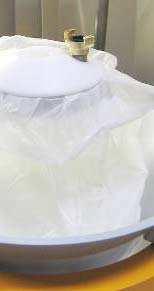
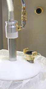
 operation, the powder bag is put in the powder bag cone.")
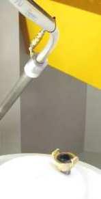
13 MagicCenter MC01 - OptiSpeeder The OptiSpeeder is suited for the automated preparation and fluidization of the coating powder. The OptiSpeeder can contain 3,5 kg powder, and can be equipped with up to 20 OptiFlow IG05 injectors. MagicCenter MC01 - Powder bag cone MagicCenter MC01 - Touch Panel All necessary operating procedures are activated by the Touch Panel. General operating sequence Powder circuit During the typical MagicCenter MC01 (7) operation, the powder bag is put in the powder bag cone. The powder is fluidized in the bag with the fluidizing/suction lance and then fed to the OptiSpeeder in the MagicCenter MC01. The fluidized powder is aspirated by the injectors and fed through the powder hoses to the guns/spray nozzles (8). The powder, which does not adhere to the workpieces, will be absorbed by the exhaust air of the booth (1) and separated from the air in the cyclone separator (2). The separated powder will be cleaned by passing through the integrated sieve (3) and fed back into the OptiSpeeder by the dense phase conveyor (4), where it will be prepared again for coating operation. MagicCenter MC01 Structure and function 11
14 Powder flow in the plant 1 Booth 6 Refuse container 2 Cyclone separator 7 MagicCenter 3 Sieve 8 Automatic guns 4 OptiFeed PP05 Powder pump 9 OptiSpeeder 5 After Filter 9 12 Structure and function MagicCenter MC01
15 Technical data MagicCenter MC01 Electrical data MagicCenter MC01 Input power Frequency Protection type Pneumatic data MagicCenter MC01 Input pressure Compressed air consumption during coating operation Compressed air consumption during cleaning (incl. OptiSpeeder and guns) Compressed air consumption during cleaning of the PP05 hose to the cyclone Water vapor content of compressed air Oil content of compressed air Dimensions MagicCenter MC01 Base area (width x depth) Overall height Weight Powder transport MagicCenter MC01 Conveying performance Recovery 3x400 V / 10 A 50/60 Hz IP54 min. 6.5 bar 15 Nm³/h 350 Nm³/h 120 Nm³/h max. 1.3 g/m³ max. 0.1 mg/kg 1400 x 2000 mm 2000 mm 230 g/min. max. 3,5 kg/min. MagicCenter MC01 Technical data 13
16

17 Start-up Set-up and assembly Note: Installation work to be done by the customer must be carried out according to local safety regulations! Preparation for start-up Compressed air supply Note: The compressed air must be free of oil and water! The MagicCenter powder management system requires a connection to a sufficient dimensioned compressed air circuit. In order to ensure a perfect operation, a pressure of 6 bar must be adjusted with the main pressure regulator. Compressed air supply Grounding of the powder management system The MagicCenter must be grounded according to the general, local safety regulations. The grounding of the powder management system must be checked regularly. MagicCenter MC01 Start-up 15
18

19 Operation with Touch-Panel Touch-Panel/operating panel The operation and monitoring of the powder management system takes place by the touch-sensitive operating panel of the control unit. The operation panel serves to initiate the function commands, which are necessary for the satisfactory operation of the powder management system. The function parameters are also entered by the control panel. These are set at the factory and, therefore, may only be changed after consultation with an ITW Gema service center. Operating panel MagicCenter MC01 Operation with Touch-Panel 17

20 Touch keypads The key functions are activated by touching the screen within this area. An illumination means that the touch keypad was directly touched. The screen layout The exit key enables switching back to the previous program mask. The remaining operating keys switch to the next corresponding program menu. Indicates the current operating mode Error messages level Password level Exit key Note: The designation (labelling) of pictograms is made in English only and is used by ITW Gema worldwide for identification of technichal support issues. The symbols are designed for the user, who will be guided through the plant by means of pictures. All operation and error messages are not displayed as pictograms, and are adapted to the local language according to the Sales contract! 18 Operation with Touch-Panel MagicCenter MC01
21 Information - Operating mode display - No release - booth not ready - - Release OK - booth is ready The signal comes from the booth control unit trough the CAN bus, or through the digital input, if it's a foreign manufacturer booth. - Control voltage is switched off - Control voltage is switched on Key functions Attention: The keys of the input field should only be pressed with fingertips and under no circumstances with fingernails or hard objects! Functionn keys - - Start the powder management system for coating Key is not activated, until boot is ready MagicCenter MC01 Operation with Touch-Panel 19
22 - For this function, no log-in is necessary - Cleaning for color change - Key is not activated, until boot is ready - For this function, no log-in is necessary - Log-in to modify parameters, configuration or change the language - Configuration - Parameters - Language change - By pressing the Help key, the phone number of the ITW Gema Helpline will be shown. Attention: The function parameters are set at the factory and may not be changed by the customer! Parameters may only be modified after consultation with an ITW Gema service center! State of the keys All keys are normal displayed during operation. However, some keys startt to blink, when their key function is to be confirmed. These blinking keys are shown in this user manual as follows: 20 Operation with Touch-Panel MagicCenter MC01

23 MagicCenter MC01 - operating modes General information The following operating modes are available: - different coating modes - Cleaning / color change - Service/parameterization The operating modes are explicitly described in the following chapters. The operation level of the control unit is designed with pictograms, so that only the really essential parameters are displayed, and the operator can therefore reach his solution quickly. Basically, the control unit is not in one of these operating modes after switching on, or after a restart. The operating modes are selected on the panel. Coating with powder recovery (spray) This coating mode allows the coating with recovery of the powder, which does not adhere to the object. Utilization of this operating mode: - Long time coating operation with the same powder and high coating quality with minimal powder loss - Immediate coating following a powder change with minimum demands on quality and the smallest possible of powder loss - Additional operating mode - Coating with small powder quantities/using up residual powder MagicCenter MC01 Operation with Touch-Panel 21
24 Coating without powder recovery (spray waste) There is no powder recovery in this coating mode - the powder, which does not adhere to the object, is fed directly to the waste. Utilization of this operating mode: - When restarting the plant or after the color change (a few minutes) - If highest coating quality claim is required - If the volume of order is very small - Additional operating mode - Coating with small powder quantities/using up residual powder Coating with small powder quantities / Using up residual powder (small lot) This coating mode is selectable in both already mentioned operating modes. Utilization of this (special) operating mode: - If the fresh powder, at the end, is used up (measured to be running low) - If a color change is pending (operator has to estimate the powder consumption) - If a small powder quantity is used (e.g. tests) Cleaning / color change (clean) This operating mode enables the user to chose, on the first cleaning screen, between Fast cleaning and Quality cleaning. In the procedure of both of these cleaning modes, there is no difference, only the preset parameters are different (cleaning times). The higher the requirement for cleanliness, the higher is the time expenditure. Each of these cleaning modes consists of two parts, the coarse cleaning and the fine cleaning. The coarse cleaning mode does recover the powder, the fine cleaning mode does not (powder loss). The cleaning of the components is partially automated, however, some of them must be cleaned manually. The Cleaning operating mode can be selected from every Coating operating mode, or from the Standby operating mode. Utilization of this operating mode: - After switching on the equipment, if very high quality is required on initial coating application - Before every color change Service / parameterization (maintenance) This operating mode enables the user to change the operating language. 22 Operation with Touch-Panel MagicCenter MC01
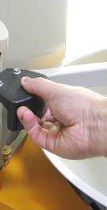
25 Coating operation Before switching on the MagicCenter MC01 Before switching on the powder center, the following points must be observed: - Observe the safety regulations - Check the grounding of the powder center, the booth and the other plant units and ensure it, if necessary - Check the compressed air supply Starting up the MagicCenter MC01 Start-up Attention: The keys of the input field should only be pressed with fingertips and under no circumstances with fingernails or hard objects! The start-up takes place according the following steps: 1. Switch on the booth (see also the booth operating instructions) - the Booth ready signal may be present 2. Switch on the control voltage in the powder management system with the key switch: - the key switch returns to its starting position - the interior lighting switches on 3. Wait for booth release - the display shows the basic menu MagicCenter MC01 Coating operation 23


26 Select desired operating mode (AUTOMATIC or MANUAL) on the booth control unit (see therefore the corresponding operating manual) 24 Coating operation MagicCenter MC01

27 Coating with powder recovery (spray) Recovery hose MagicCenter MC01 Coating operation 25

28 5. - the fluidization switches on - now the coating operation can begin 6. If necessary, replace the powder bag, see also "Replacing the powder bag (change bag)" 7. If necessary, switch on the exhaust air manually The exhaust air stops automatically after a certain period 8. The key closes the Coating menu and returns to the main menu 26 Coating operation MagicCenter MC01

29 Coating without powder recovery (spray waste) Recovery hose 4. MagicCenter MC01 Coating operation 27
 can be selected, if desired 9.")
30 5. - the Fluidization switches on - now the coating operation can begin 6. If necessary, replace the powder bag, see also "Replacing the powder bag (change bag)" 7. If necessary, switch on the exhaust air manually The exhaust air stops automatically after a certain period 8. The operating mode Coating with powder recovery (spray) can be selected, if desired 9. The key closes the Coating menu and returns to the main menu 28 Coating operation MagicCenter MC01
31 Coating with small powder quantities / Using up residual powder (small lot) Note: This operating mode can be selected from the "Coating with powder recovery" or "Coating without powder recovery" operating mode! Coating with small powder volumes with powder recovery The key closes this menu and returns to the last menu MagicCenter MC01 Coating operation 29
32 Coating with small powder volumes without powder recovery The key closes this menu and returns to the last menu 30 Coating operation MagicCenter MC01


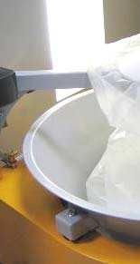
33 Replacing the powder bag (change bag) 1. Check visually the powder level in the bag cone 2. Hold the full powder bag ready Removee the used powder bag with the residual powder MagicCenter MC01 Coating operation 31


34 Coating operation MagicCenter MC01

35 15. Press the returns to the last menu key to confirm the change The display 16. The key closes this menu and switches back to the last menu without powder bag change Starting up the MagicCenter MC01 after an emergency stop 1. Switch on the booth (see the booth operating instructions) - the Booth ready signal may be present 2. Switch on the control voltage in the powder management system with the key switch: the key switch returns to its starting position the interior lighting switches on the display shows the basic menu 3. Select the desired operating mode MagicCenter MC01 Coating operation 333
36 Switching off the MagicCenter MC01 (after each work day) The following steps must be taken to switch off the powder center: 1. Check if all the workpieces have been coated 2. Clean the MagicCenter thoroughly, in order to avoid powder accumulation (see therefore in chapter "Cleaning / Color change") 3. Press the key The following menu appears on the display: - the level control is switched off - the vibrating table switches off 4. Switch off the powder management system by key switch - the interior lighting expires 5. Switch off the main switch 34 Coating operation MagicCenter MC01
37 Cleaning / color change Note: Very much air will be required for the cleaning procedure! A pressure sensor detects the current pressuree in the supply line after the input pressure regulator (6 bar), and compares it to the threshold value which was set in the parameters. If the threshold value is not reached for 3 seconds, the cleaning procedure will be interrupted. The cleaning interruption takes at least 30 seconds. Afterwards the cleaning procedure continues, if the pressure amounts to > 5.5 bar. Cleaning operating mode (clean) General information The Cleaning operating mode offers two cleaning possibilities: - - Fast cleaning Quality cleaning Cleaning procedure 1. MagicCenter MC01 Cleaning / color change 35


38 Connect the recovery hose Press the The display or key switches to the following menu 36 Cleaning / color change MagicCenter MC01


 are processed now 11. 12.")
39 8. - The automated cleaning procedure is started - The powder from the OptiSpeeder and from the booth will be fed back in the powder bag 9. The booth cleaning can get started now. 10. The cleaning sequences (shown as symbols in the bottom line) are processed now MagicCenter MC01 Cleaning / color change 37


40 13. When the cleaning process is completed, the control switches automatically to the next menu: 14. Recovery hose Open the monocyclone Slowly swing out the sieve and clean it with the compressed air gun 18. Attention: In order to avoid damage to the sieve when blowing through the transport hose, make sure that the sieve is swung out completely during the cleaning process! 38 Cleaning / color change MagicCenter MC01

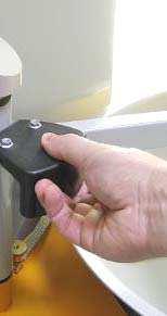
41 19. Press the key The cleaning of the recovery hose will be started. 20. Press the button on the monocyclone. The cleaning process is started. 21. The hose is blown off in pulses The procedure can be stopped or resumed manually by the user. 22. Swing the funnel on the cyclone slowly away and, at the same time, clean it off with the compressed air gun 23. Clean the inside of the cyclone with the cleaning lance 24. Close the sieve and funnel on the cyclone again 25. Put the powder management system into operation (see chapter "Start-up") MagicCenter MC01 Cleaning / color change 39
42
43 Service/ /parameterization Attention: All MagicCenter settings are set at the factory and may not be changed by the customer! Parameters may only be modified after consultation with an ITW Gema service center! Changing operating language In order to input the settings on the operating panel, the plant must be in operation. To do this, proceed as follows: 1. Switch on the booth (see the booth operating instructions) - the Booth ready signal may be present 2. Switch on the control voltage in the powder management system with the key switch: the key switch returns to its starting position the interior lighting switches on the display shows the basic menu 3. MagicCenter MC01 Service/parameterization 41
44 Press the key, the previous menu appears 42 Service/parameterization MagicCenter MC01
45 Messages Error messages If faults occur in the powder management system, an error message shown in red font appears on the display. The causes of these errors must be eliminated, before further procedures can be carried out (see therefore the troubleshooting guide). If the error has been eliminated, the display returns to the previous menu again. No. Display text Description Activity 01 Clean the Level base sensor OptiSpeeder empty, level sensor indicates the status, no coating operation possible: Powder accumulation on level sensor Sensor defective Cable defective 02 Clean the Level top sensor OptiSpeeder empty, level sensor indicates the status, no coating operation possible: 03 Clean the Cyclone level base sensor Powder accumulation on level sensor Sensor defective Cable defective Cyclone funnel empty, level sensor indicates the status, no coating operation possible: Open OptiSpeeder service cover and front panel: - Clean the sensor - Readjust the sensor sensitivity - Check the fluidizing of the sensor if necessary, increase the fluidizing air pressure - Remove the fluidizing air hose and ckeck it replace replace Open OptiSpeeder service cover and front panel: - Clean the sensor - Readjust the sensor sensitivity - Check the fluidizing of the sensor if necessary, increase the fluidizing air pressure - Remove the fluidizing air hose and ckeck it replace replace MagicCenter MC01 Messages 43
46 No. Display text Description Activity 04 Clean the Cyclone level top sensor Powder accumulation on level sensor Sensor defective Cable defective This function not active at the moment 05 Open service cover OptiSpeeder service cover is open Proximity switch defect Cable defective 06 Air supply low pressure Air pressure dropped below the threshold value of 4,5 bar Sudden pressure decrease 07 Cylinder does not open OptiSpeeder cylinder does not move to the preset position, control unit switches to Standby mode 08 Cylinder does not close OptiSpeeder cylinder does not move to the preset position, control unit switches to Standby mode 09 Cylinder limit switch defective Both limit switches illuminate, control unit switches to Standby mode 10 Vibrator defective Motor protection switch Q6 has reacted 13 Powder recovery pump conveying problem Vibrator defective Cable broken Powder pump does not function properly - Clean the sensor - Readjust the sensor sensitivity - Check the fluidizing of the sensor if necessary, increase the fluidizing air pressure - Remove the fluidizing air hose and ckeck it replace replace Close the cover Check the function, if necessary, replace it replace Increase the preessure at the main pressure regulator Check the compressed air supply Check the compressed air supply, if necessary, wait until the system has reached the operating pressure Remove lateral panel: - Check the cylinder for contamination and clean, if necessary - Check the compressed air - Restart, select the corresponding function - Contact an ITW Gema service center Remove lateral panel: - Check the cylinder for contamination and clean, if necessary - Check the compressed air - Restart, select the corresponding function - Contact an ITW Gema service center - Contact an ITW Gema service center Remove the small maintenance panel and switch on the motor protection switch again. With repeated Alarms, contact an ITW Gema service center replace replace 44 Messages MagicCenter MC01
47 No. Display text Description Activity 14 Powder recovery pump overpressure - Pump defective - see the corresponding operating manual OptiFeed PP05 - Hose clogged Check the recovery system - Check the level sensor (see also Error message no. 03) - Check the cyclone funnel for powder abrasion Powder pump is switched off - Hose clogged or connected incorrectly - Pressure sensor at the OptiFeed PP05 Powder pump defective V valve block failure Safety equipment (F7) has reacted, control unit switches to Standby mode 16 Fuse Fxx defective Fuse (1 AT) in the WAGO-Modul A1 defective, control unit switches to Standby mode 19 Powder alert in OptiSpeeder Powder warning, flashlight activated 20 Powder shortage in OptiSpeeder Powder bag empty, chain conveyor is stopped, flashlight activated 21 CAN bus malfunction No communication with CM10/CM20 CAN-Bus participant defective - Contact an ITW Gema service center Check the recovery system and/or connect correctly replace (see also corresponding OptiFeed PP05 operating manual) Check the 24 VDC Power pack (G4) Check the safety equipment whether all 4 LEDs illuminate green - If one or more LEDs illuminate, reset the correcponding channel and if necessary, restart Replace the fuse, otherwise contact an ITW Gema service center Check the powder bag, otherwise powder shortage Replacing the powder bag Switch on the CM10/CM20 superordinated control unit Contact an ITW Gema service center Warnings Warnings shown with a green font are notes for the operating personnel. If a warning is present, it appears on the display. The warning must be acknowledged. Afterwards, the last illustration shown appears on the display. No. Display text Description Activity 51 Cleaning not completed Cleaning not completely terminated because of abort or power failure. Press the "cleaning broken" key, in order to acknowledge it 52 Key switch off or Emergency stop Key switch off or Emergency stop Rotate the key switch clockwise MagicCenter MC01 Messages 45
48
49 Maintenance Daily after longer working interruptions and at the end of shift - Before switching off the plant, the OptiSpeeder must be emptied and cleaned Check weekly - Check the injector nozzles and replace them, if necessary Check every 6 months - Check the cylinder guideways and gaskets and replace them, if necessary MagicCenter MC01 Maintenance 47
50
51 Spare parts list Ordering spare parts When ordering spare parts for powder coating equipment, please indicate the following specifications: - Type and serial number of your powder coating equipment - Order number, quantity and description of each spare part Example: - Type MagicCenter MC01 Serial number Order no , 1 piece, Clamp - Ø 18/15 mm When ordering cable or hose material, the required length must also be given. The spare part numbers of this yard/meter ware is always marked with an *. The wearing parts are always marked with a #. All dimensions of plastic hoses are specified with the external and internal diameter: Example: Ø 8/6 mm, 8 mm outside diameter (o/d) / 6 mm inside diameter (i/d) WARNING! Only original ITW Gema spare parts should be used, because the explosion protection will also be preserved that way. The use of spare parts from other manufacturers will invalidate the ITW Gema guarantee conditions! MagicCenter MC01 Spare parts list 49
 269 018 Touch panel control")
52 Touch panel control unit 1 Touch panel - 5.7" Compact Flash card - 32 MB (not shown) Touch panel control unit 50 Spare parts list MagicCenter MC01
53 MagicCenter MC01 Spare parts list 51
OptiCenter OC01 Powder management center
 En Operating instructions and spare parts list OptiCenter OC01 Powder management center Translation of the original operating instructions Documentation - OptiCenter OC01 Copyright 2009 Gema Switzerland
Operating instructions and spare parts list. Waste powder conveying from recovery container WPS01
 En Operating instructions and spare parts list Waste powder conveying from recovery container WPS01 Documentation WPS01-PP03 Copyright 2006 ITW Gema GmbH All rights reserved. This publication is protected
WPS02 Waste powder conveying with BIG-BAG station
 En Operating instructions and spare parts list WPS02 Waste powder conveying with BIG-BAG station Translation of the original operating instructions Documentation WPS02 Copyright 2008 ITW Gema GmbH All
Application cup for OptiFlex 2 GM03 manual powder gun
 En Operating instructions and spare parts list Application cup for OptiFlex 2 GM03 manual powder gun Translation of the original operating instructions Documentation OptiFlex GM03 application cup Copyright
Operating instructions and spare parts list. LM01 Level sensor. Translation of the original operating instructions
 En Operating instructions and spare parts list LM01 Level sensor Translation of the original operating instructions Documentation LM01 Level sensor Copyright 2005 Gema Switzerland GmbH All rights reserved.
OptiSpray F Manual coating equipment
 En Operating instructions and spare parts list OptiSpray F Manual coating equipment Translation of the original operating instructions Documentation OptiSpray F Manual coating equipment Copyright 2006
Operating instructions and spare parts list. OptiFlow powder injector (IG02 type)
") En Operating instructions and spare parts list OptiFlow powder injector (IG02 type) Documentation OptiFlow powder injector (IG02 type) Copyright 2004 ITW Gema AG All rights reserved. This publication is
En Operating instructions and spare parts list OptiFlow powder injector (IG02 type) Documentation OptiFlow powder injector (IG02 type) Copyright 2004 ITW Gema AG All rights reserved. This publication is
OptiFlow powder injector (IG02 type)
") En Operating instructions and spare parts list OptiFlow powder injector (IG02 type) Translation of the original operating instructions Documentation OptiFlow powder injector (IG02 type) Copyright 2004
En Operating instructions and spare parts list OptiFlow powder injector (IG02 type) Translation of the original operating instructions Documentation OptiFlow powder injector (IG02 type) Copyright 2004
OptiCenter OC02 Powder management center
 1011 502 En Operating instructions and spare parts list OptiCenter OC02 Powder management center Translation of the original operating instructions Documentation OptiCenter OC02 Copyright 2008 Gema Switzerland
OptiFlow Plug-in injector (IG02)
") E Operating Instructions and Spare Parts List OptiFlow Plug-in injector (IG02) IG02 OptiFlow Injector 9 10 IG02 OptiFlow Injector Table of Contents 1 OptiFlow plug-in injector for organic powders...............................
E Operating Instructions and Spare Parts List OptiFlow Plug-in injector (IG02) IG02 OptiFlow Injector 9 10 IG02 OptiFlow Injector Table of Contents 1 OptiFlow plug-in injector for organic powders...............................
Operating Instructions and Spare Parts List. Tilt Table FPS13. Ausgabe 07/02. Tilt Table FPS13
 E Operating Instructions and Spare Parts List 15 Copyright 2000 ITW Gema AG., CH-9015 St. Gall All rights reserved. This publication is protected by copyright. Unauthorized copying is prohibited by law.
Operating instructions and spare parts list. XT08 Horizontal axis
 En Operating instructions and spare parts list XT08 Horizontal axis Documentation XT08 Copyright 2004 ITW Gema AG All rights reserved. This publication is protected by copyright. Unauthorized copying is
FPS16 Fresh powder system
 En Operating instructions and spare parts list FPS16 Fresh powder system Translation of the original operating instructions Documentation FPS16 Fresh powder system Copyright 2005 Gema Switzerland GmbH
Powder injector OptiFlow IG07
 Rev. 00 1011 527 EN Operating instructions and Spare parts list Powder injector OptiFlow IG07 Translation of the original operating instructions Documentation OptiFlow IG07 Copyright 2017 Gema Switzerland
Manual coating equipment OptiFlex 2 B
 En Operating instructions and spare parts list Manual coating equipment OptiFlex 2 B Translation of the original operating instructions Documentation OptiFlex 2 B Copyright 2010 ITW Gema GmbH All rights
XT 6 Horizontal Axis
 E Operating Instructions and Spare Parts List 11 12 Table of Contents................................................... 1 1. Field of Application........................................... 1 2. Description.................................................
Operating instructions and spare parts list. PZ Powder center with Gematic control unit
 En Operating instructions and spare parts list PZ Powder center with Gematic control unit Documentation PZ Powder center with Gematic control unit Copyright 2004 ITW Gema AG All rights reserved. This publication
OptiCenter OC05 Powder management center
 1011 506 En Operating instructions and spare parts list OptiCenter OC05 Powder management center Translation of the original operating instructions Documentation OptiCenter OC05 Copyright 2008 Gema Switzerland
Manual powder gun OptiFlex 2 GM03
 En Operating instructions and spare parts list Manual powder gun OptiFlex 2 GM03 Translation of the original operating instructions Documentation OptiFlex 2 GM03 Copyright 2010 ITW Gema GmbH All rights
EasySelect GM01-E Manual Powder Gun
 E Operating Instructions and Spare parts list EasySelect GM01-E Manual Powder Gun EasySelect GM01-E 25 26 EasySelect GM01-E Table of Contents Safety rules Safety rules for electrostatic powder coating
OptiGun 2-AE1 Enamel automatic gun (GA02-E1 type)
") En Operating instructions and spare parts list OptiGun 2-AE1 Enamel automatic gun (GA02-E1 type) II 2 D Translation of the original operating instructions Documentation OptiGun 2-AE1 Enamel automatic gun
En Operating instructions and spare parts list OptiGun 2-AE1 Enamel automatic gun (GA02-E1 type) II 2 D Translation of the original operating instructions Documentation OptiGun 2-AE1 Enamel automatic gun
OptiGun 2-AE Automatic Powder Gun (GA02)
") E Operating Instructions and Spare Parts List Automatic Powder Gun (GA02) 31 32 Table of Contents 1. Operating Instructions................................................... 1 1.1. Safety rules for electrostatic
E Operating Instructions and Spare Parts List Automatic Powder Gun (GA02) 31 32 Table of Contents 1. Operating Instructions................................................... 1 1.1. Safety rules for electrostatic
Operating instructions and spare parts list. MagicCylinder II Powder coating booth
 En Operating instructions and spare parts list MagicCylinder II Powder coating booth Documentation - Powder coating booth MagicCylinder II Copyright 2007 ITW Gema GmbH All rights reserved. This publication
Operating instructions and spare parts list. OptiFlex F. Manual coating equipment
 En Operating instructions and spare parts list OptiFlex F Manual coating equipment Documentation OptiFlex B manual coating equipment Copyright 2005 ITW Gema AG All rights reserved. This publication is
Operating instructions and spare parts list FPS14 Fresh powder system
 En Operating instructions and spare parts list FPS14 Fresh powder system 0102 II 3 D Documentation FPS14 Fresh powder system Copyright 2004 ITW Gema AG All rights reserved. This publication is protected
Operating instructions and spare parts list. OptiFlex S. Manual coating equipment
 En Operating instructions and spare parts list OptiFlex S Manual coating equipment Documentation OptiFlex S manual coating equipment Copyright 2005 ITW Gema AG All rights reserved. This publication is
Powder coating equipment OptiFlex 2 BN (Boron Nitride)
") En Operating instructions and spare parts list Powder coating equipment OptiFlex 2 BN (Boron Nitride) WARNING: This equipment was developed for use with electrically non-conducting powders. The use of
En Operating instructions and spare parts list Powder coating equipment OptiFlex 2 BN (Boron Nitride) WARNING: This equipment was developed for use with electrically non-conducting powders. The use of
OptiGun GA03 Automatic powder gun
 1010 772 En Operating instructions and spare parts list OptiGun GA03 Automatic powder gun 0102 II 2D Translation of the original operating instructions Documentation OptiGun GA03 Automatic powder gun Copyright
OptiGun GA03-P Automatic powder gun
 1011 460 En Operating instructions and spare parts list OptiGun GA03-P Automatic powder gun 0102 II 2D Translation of the original operating instructions Documentation OptiGun GA03-P Automatic powder gun
Operating instructions and spare parts list OptiStar CG07 Manual gun control unit
 En Operating instructions and spare parts list OptiStar CG07 Manual gun control unit Order no. 1004 068 Documentation OptiStar CG07 Manual gun control unit Copyright 2006 ITW Gema AG All rights reserved.
Quick reference guide. OptiFlex F. Manual coating equipment. Translation of the original operating instructions
 En Quick reference guide OptiFlex F Manual coating equipment Translation of the original operating instructions Quick reference guide OptiFlex F manual coating equipment Copyright 2006 Gema Switzerland
Operating instructions and spare parts list. OptiSelect. Manual powder gun
 En Operating instructions and spare parts list OptiSelect Manual powder gun Documentation OptiSelect manual powder gun Copyright 2005 ITW Gema AG All rights reserved. This publication is protected by copyright.
Operating instructions and spare parts list. FPS15 Tilt table
 En Operating instructions and spare parts list FPS5 Tilt table Documentation FPS5 Tilt table Copyright 004 ITW Gema AG All rights reserved. This publication is protected by copyright. Unauthorized copying
Operating instructions and spare parts list. OptiStar CG07 Manual Gun control unit
 En Operating instructions and spare parts list OptiStar CG07 Manual Gun control unit Documentation OptiStar CG07 Gun control unit Copyright 2005 ITW Gema AG All rights reserved. This publication is protected
Operating Instructions and Spare Parts List. ZA02 Reciprocator. EIssued 08/03. ZA02 Reciprocator 29
 E Operating Instructions and Spare Parts List 29 30 Table of Contents Safety Rules Technical data for the ZA 02 Reciprocator Schematic Diagram 1. Description of function..................................................
EasySelect-Cup Manual Powder Gun
 E Operating Instructions and Spare parts list EasySelect-Cup Manual Powder Gun EasySelect-Cup 27 28 EasySelect-Cup Table of Contents Safety rules EasySelect-Cup Manual Powder gun...........................................
CRS-D Powder Coating Booth with Reverse Jet Cleaning System
 Operating Instructions CRS-D Powder Coating Booth with Reverse Jet Cleaning System CRS-D (J) 27 1 1 1 2 2 2 4 4 4 3 3 3 CRS-D Booth with Reverse Jet Cleaning System 1 10 2 3 9 12 11 11 1 Exhaust air unit
Rev EN. Operating instructions and Spare parts list. Vertical axis ZA13. Translation of the original operating instructions
 Rev. 00 1011 516 EN Operating instructions and Spare parts list Vertical axis ZA13 Translation of the original operating instructions Documentation ZA13 Copyright 2017 Gema Switzerland GmbH All rights
Manual gun OptiSelect GM03
 Rev. 01 1011 454 EN Operating instructions and Spare parts list Manual gun OptiSelect GM03 Translation of the original operating instructions Documentation OptiSelect GM03 Copyright 2018 Gema Switzerland
Robot gun RobotGun GM03-R
 Rev. 00 1011 533 EN Operating instructions and Spare parts list Robot gun RobotGun GM03-R Translation of the original operating instructions Documentation RobotGun GM03-R Copyright 2017 Gema Switzerland
Manual coating equipment OptiFlex 2 B
 En Quick reference guide Manual coating equipment Translation of the original operating instructions Documentation Copyright 2010 Gema Switzerland GmbH All rights reserved. This publication is protected
Manual equipment OptiFlex 2 F
 Rev. 00 1007 142 EN Quick reference guide Manual equipment OptiFlex 2 F Translation of the original operating instructions Documentation OptiFlex 2 F Copyright 2016 Gema Switzerland GmbH All rights reserved.
KeContact P20. User manual
 KeContact P20 User manual Comments to this manual In this manual you will find warnings against possible dangerous situations. The used symbols apply to the following meanings:!! WARNING! Indicates a potentially
OptiCenter (OC01/OC02)
") 1 OptiCenter OC01/02 Tender Document 1 OptiCenter (OC01/OC02) Your powder management solution presents a new generation of powder management systems: the new OptiCenterO1/O2. It is clean, it is quick,
1 OptiCenter OC01/02 Tender Document 1 OptiCenter (OC01/OC02) Your powder management solution presents a new generation of powder management systems: the new OptiCenterO1/O2. It is clean, it is quick,
Operating instructions and spare parts list. ZA06 Reciprocator
 En Operating instructions and spare parts list ZA06 Reciprocator Documentation ZA06 Reciprocator Copyright 2006 ITW Gema GmbH All rights reserved. This publication is protected by copyright. Unauthorized
PG 1-A Automatic Powder Gun
 E Operating Instructions and Spare Parts List Automatic Powder Gun 25 26 Tabel of Contents Safety rules for electrostatic powder coating operations Automatic powder gun...........................................
Operating instructions
 Operating instructions Digital tank contents indicator DTA 10 DTA 10 DTA 10 0 4.0 m fuel oil 0 3.5 m water Read instructions before using device! Observe all safety information! Keep instructions for future
EASY 1-F Powder Coating Equipment
 E Operating Instructions and Spare parts list EASY 1-F Powder Coating Equipment 0102 II (2) D EASY 1-F ELECTROSTATIC POWER MANUAL EQUIPMENT 13 14 1 2 12 11 10 9 8 3 4 5 6 7 1 EasyTronic control unit 2
PG 2-A Automatic Powder Gun (and PG 2-AX Automatic Powder Gun for Quick Colour Changes)
") E Operating Instructions and Spare Parts List Automatic Powder Gun (and X Automatic Powder Gun for Quick Colour Changes) 31 32 Table of Contents Automatic Powder Gun...........................................
E Operating Instructions and Spare Parts List Automatic Powder Gun (and X Automatic Powder Gun for Quick Colour Changes) 31 32 Table of Contents Automatic Powder Gun...........................................
User Guide. Lubricus Lubrication System LUB-D1/LUB-D2/LUB-D3/LUB-D4 (24 VDC)
") User Guide Lubricus Lubrication System LUB-D1/LUB-D2/LUB-D3/LUB-D4 (24 VDC) version 04/2013 Content General Information 3 Warning 3 Scope of Supply 3 Overview 3 General safety details 4 Intended use 4
User Guide Lubricus Lubrication System LUB-D1/LUB-D2/LUB-D3/LUB-D4 (24 VDC) version 04/2013 Content General Information 3 Warning 3 Scope of Supply 3 Overview 3 General safety details 4 Intended use 4
Swing Piston Compressors and Vacuum Pumps
 Swing Piston Compressors and Vacuum Pumps NPK 018 AC Pressure NPK 018 DC Pressure NPK 018 AC Vacuum NPK 018 DC Vacuum Operating and Installation Instructions Read and observe these Operating and Installation
SPARK PLUG CLEANING KIT OPERATING MANUAL
 SPARK PLUG CLEANING KIT OPERATING MANUAL Spark Plugs - Tools & Accessories P/N 01.20.002 Rev. 08/2015 Copyright Copyright 2015 MOTORTECH GmbH. All rights reserved. Distribution and reproduction of this
Operating Instructions and Spare Parts List. PG 1-Cup Gun. Issued 09/98
 E Operating Instructions and Spare Parts List 27 28 Table of Contents Directions for use Electrostatic Manual Spraying equipment for Powder Coating Safety rules for the electrostatic powder coating Technical
Type 3360, Service Manual. Serviceanleitung Service Manuel
 Electromotive control valve Elektromotorisches Regelventil Vanne de régulation électromotorisée Service Manual Serviceanleitung Service Manuel We reserve the right to make technical changes without notice.
SENTRY ISOBUS Tip Flow Monitor. Software Version 1.00
 SENTRY 6141 U S E R M A N U A L ISOBUS Tip Flow Monitor Software Version 1.00 Copyrights 2016 TeeJet Technologies. All rights reserved. No part of this document or the computer programs described in it
Operating instructions Spray nozzle SDU
 Operating instructions Spray nozzle SDU INDEX Page 1. General... 2 2. Safety... 2 4 A. Nozzles type... 5 B. Nozzles inserts... 5 C. Revision... 5 D. Monitoring... 6 E. Heating... 6 F. Accessories... 6
Wind Power Inverter WINDY BOY 5000A/6000A
 Wind Power Inverter WINDY BOY 5000A/6000A User Manual WB5A-6A-BA-BEN114530 TBEN-WB50-60A Version 3.0 EN SMA Solar Technology AG Table of Contents Table of Contents 1 Information on this Manual.........................
Exchange of rollers from the XTS-Mover
 Service documentation for AT901-0050-0550 and AT9011-00x0-0550 Version: Date: 1.0 0.10.017 Table of contents Table of contents 1 Foreword... 5 1.1 Notes on the documentation... 5 1. Documentation issue
Instruction Manual. Automatic Fuel Oil De-aerator Flow-Control. Flow-Control 3/K-1 # Flow-Control 3/K-2 # 70019
 Mess-, Regel- und Überwachungsgeräte für Haustechnik, Industrie und Umweltschutz Lindenstraße 20 DE-74363 Güglingen Telefon: +49(0)7135-102-0 Service: +49(0)7135-102-211 Telefax: +49(0)7135-102-147 E-Mail:
INSTRUCTION MANUAL. I/P Converter DSG BXXY3Z DSG BXXY4Z
 INSTRUCTION MANUAL I/P Converter DSG BXXY3Z DSG BXXY4Z Revision 2.0 3.626 016136 en Page 1/15 Should you have any questions concerning the I/P converter, please contact the Service Department of the Product
SI AT A22. English. Printed: Doc-Nr: PUB / / 000 / 01
 SI AT A22 English 1 Information about the documentation 1.1 About this documentation Read this documentation before initial operation or use. This is a prerequisite for safe, trouble-free handling and
SI AT A22. English. Printed: Doc-Nr: PUB / / 000 / 03
 SI AT A22 English 1 Information about the documentation 1.1 About this documentation Read this documentation before initial operation or use. This is a prerequisite for safe, trouble-free handling and
MPS 1-F / MPS 2-F Manual Powder System
 E Operating Instructions and Spare Parts List MPS -F / MPS -F Manual Powder System MPS -F / MPS -F MPS -F / MPS -F Table of contents Directions for use Safety rules for the electrostatic powder coating
Colormax Powder Coating System Color Change Process
 Nordson Corporation OPERATOR S CARD P/N 1015049B Colormax Powder Coating System Color Change Process Safety WARNING: Allow only qualified personnel to perform the following tasks. Follow the safety instructions
Operating manual. original operating manual. HDA eco Box 12/24V DC Automatic Dispenser. Translation of the. Item No.:
 Operating manual HDA eco Box 12/24V DC Automatic Dispenser Item No.: 110 500 900 Translation of the original operating manual Important! Copyright The operating manual is always to be read before commissioning
Installation, Operating & Maintenance Instructions. All-metal gate valve with compact or extended pneumatic actuator
 Installation, Operating & Maintenance Instructions All-metal gate valve with compact or extended pneumatic actuator Series 48 DN 16 320 mm (I.D. ⅝" 12") This manual is valid for the following product ordering
Original Operating Manual
 2010-10-29 Original Operating Manual Control Panel Comfort for Pedelecs Series 4313 Save for future use! Marquardt GmbH Schlossstraße 16 78604 Rietheim-Weilheim E-mail: marquardt@marquardt.de Website:
VAPORIX-PCM. Technical Documentation. Corrective control module for connection to VAPORIX-Control. Version: 3 Edition: Art.
 Technical Documentation VAPORIX-PCM Corrective control module for connection to VAPORIX-Control Version: 3 Edition: 2016-08 Art. No: 350102 FAFNIR GmbH Schnackenburgallee 149 c 22525 Hamburg, Germany Tel.:
Oil-free piston compressors KK and piston vacuum pumps KV
 Oil-free piston compressors KK and piston vacuum pumps KV Installation and Operating Instructions 0678106030L02 1707V003 Contents Important information 1 About this document 2 1.1 Warnings and symbols
Printed: Doc-Nr: PUB / / 000 / 00
 ORIGINAL OPERATING INSTRUCTIONS Hilti HTE-P 33 dispenser It is essential that the operating instructions are read before the tool is operated for the first time. Always keep these operating instructions
VARIFUEL MAINTENANCE AND REPAIR INSTRUCTIONS
 VARIFUEL2 200-120 MAINTENANCE AND REPAIR INSTRUCTIONS MOTORTECH Gas Regulation P/N 01.50.008-200-120-EN Rev. 06/2015 Copyright Copyright 2015 MOTORTECH GmbH. All rights reserved. Distribution and reproduction
Mod: KLD6-12/35XLAS-N
 12/2011 Mod: KLD6-12/35XLAS-N Production code: 1914070 INSTRUCTION MANUAL LOGIC LINE PLUS HOOD Reseller Stamp for Warranty Dear customer, Above all, thank you for choosing our product and we would like
Installation and Operating Manual for Tank and Equipment Cleaning Nozzles Series 5TM
 Installation and Operating Manual for Tank and Equipment Cleaning Nozzles Series 5TM 150 150 150 This instruction manual contains proprietary information which is protected by copyright laws. No part of
original operating manual Operating manual Translation of the Item-No.: ,
 Translation of the original operating manual Operating manual Item-No.: 015 431 551, 015 431 581 Important! Copyright The operating manual is always to be read before commissioning the equipment. No warranty
Micro Diaphragm Gas Sampling Pumps
 Operating and Installation Instructions Micro Diaphragm Gas Sampling Pumps Type range: NMP 03 KP DC-B1 NMP 03 KP DC-S NMP 03 KP DC-B3 NMP 03 KP DC-M NMP 03 KP DC-L You have selected a high-quality KNF
Off-line filter system
 Off-line filter system 30 NFF2, 50 NFF2, 80 NFF2 RE 51433-B/04.10 Replaces: -.- English Operating instructions The data specified above only serve to describe the product. No statements concerning a certain
I. Safety precautions
 . Safety precautions The items described in these instructions and on the inverter itself are very important so that you can use the inverter safely, prevent injury to yourself and other people around
DC Master 24/ A
 USERS MANUAL DC Master 24/12 50-60A DC-DC converter MASTERVOLT Snijdersbergweg 93, 1105 AN Amsterdam The Netherlands Tel.: +31-20-3422100 Fax.: +31-20-6971006 www.mastervolt.com ENGLISH Copyright 2015
Tension Meter. Edition FT 03.E. FT Series. Instruction Manual. Valid as of: Please keep the manual for future reference!
 Tension Meter FT Series S C H M I D T c o n t r o l i n s t r u m e n t s Edition FT 03.E Model FT Instruction Manual Valid as of: 01.09.2011 Please keep the manual for future reference! Contents 1 Warranty
Inverter / Charger Accessory for Steca Solarix PLI Phase / Parallel Kit. Installation and operating instructions Z01 17.
 Inverter / Charger Accessory for Steca Solarix PLI 5000-48 3-Phase / Parallel Kit Installation and operating instructions GB Z01 17.31 Table of Contents About this Manual... 2 Purpose... 2 Scope... 2 Keywords
Prodigy Powder Port Feed Center
 Prodigy Powder Port Feed Center Customer Product Manual Issued 2/ For parts and technical support, call the Finishing Customer Support Center at (800) 433-939. This document is subject to change without
INSTALLATION USER MANUAL
 INSTALLATION & USER MANUAL DYNAMIC LOAD MANAGEMENT -PREMIUM- This document is copyrighted, 2016 by Circontrol, S.A. All rights are reserved. Circontrol, S.A. reserves the right to make improvements to
Relay Retrofit Program Cutting Tool Safety Guide
 Relay Retrofit Program Cutting Tool Safety Guide Copyright This document and parts thereof must not be reproduced or copied without written permission from ABB, and the contents thereof must not be imparted
VARIFUEL MAINTENANCE AND REPAIR INSTRUCTIONS
 VARIFUEL2 140-65 MAINTENANCE AND REPAIR INSTRUCTIONS MOTORTECH Gas Regulation P/N 01.50.008-140-65-EN Rev. 06/2015 Copyright Copyright 2015 MOTORTECH GmbH. All rights reserved. Distribution and reproduction
The information in this instruction manual is subject to modifications without prior notice and is the exclusive property of Zorzini.
 Dear Customer, Thank you for choosing a Zorzini S.p.A. product. Zorzini manway doors and manhole covers 1 are designed and manufactured according to the highest standards in regards safety, functionality
2 TONNE TROLLEY JACK
 2 TONNE TROLLEY JACK 61829 IMPORTANT: Please read these instructions carefully to ensure the safe and effective use of this product and save these instructions for future reference. This manual has been
MPS 1-B / MPS 2-B Manual Powder System
 E Operating Instructions and Spare Parts List MPS -B / MPS -B Manual Powder System MPS -B / MPS -B 7 Issued / - V. Issued / - V. 8 MPS -B / MPS -B Table of Contents Directions for use Safety rules for
Inhalt. Granule jet blasting device PG 5 8. Owner s Manual. Translation of the original instructions
 Inhalt Granule jet blasting device PG 5 8 Owner s Manual Translation of the original instructions 1 This instruction manual is protected by copyright. No use outwith the strict limitations of copyright
Powder Feed Center. Customer Product Manual Part A03
 Powder Feed Center Customer Product Manual Issued 1/09 For parts and technical support, call the Industrial Coating Systems Customer Support Center at (800) 433-9319 or contact your local Nordson representative.
Accessories for Wind Power Inverter WINDY BOY PROTECTION BOX 400 / 500 / 600
 Accessories for Wind Power Inverter WINDY BOY PROTECTION BOX 400 / 500 / 600 Installation Guide WBP-Box-IEN103320 IMEN-WBP-BOX Version 2.0 EN SMA Solar Technology AG Table of Contents Table of Contents
RediCoat by Nordson. Hopper and VBF Dolly Systems. Customer Product Manual Part A Issued 10/07
 RediCoat by Nordson Hopper and VBF Dolly Systems Customer Product Manual Part 1082648A Issued 10/07 This document is subject to change without notice. Nordson Corporation Amherst, Ohio USA 2 Table of Contents
2-PHASE STEPPING MOTOR DRIVER FE Z5 DISPENSE
 2-PHASE STEPPING MOTOR DRIVER FE Z5 DISPENSE For Diaphragm Dosing Pumps FEM 1.02_.55 / FEM 1.09_.55 Controller board package, without pump: ID 160536 Operating and Installation Manual It is important to
Installation, Operating & Maintenance Instructions. UHV gate valve with pneumatic actuator. Series 108 DN mm (I. D. 2½ 8 )
") Installation, Operating & Maintenance Instructions UHV gate valve with pneumatic actuator Series 108 DN 63 200 mm (I. D. 2½ 8 ) This manual is valid for the following product ordering numbers: 108.. -.
Installation, Operating & Maintenance Instructions UHV gate valve with pneumatic actuator Series 108 DN 63 200 mm (I. D. 2½ 8 ) This manual is valid for the following product ordering numbers: 108.. -.
Prodigy HDLV Pump. Customer Product Manual Part A02
 Prodigy HDLV Pump Customer Product Manual Issued 1/07 For parts and technical support, call the Industrial Coating Systems Customer Support Center at (800) 433-9319 or contact your local Nordson representative.
Assembly and Maintenance Manual Type ASNU
 Assembly and Maintenance Manual Type ASNU Hatschekstr.36 69126 Heidelberg Germany Tel +49(0)6221 30470 Fax +49(0)6221 304731 info@stieber.de www.stieber.de Date of issue: 30.05.2018 GB Revision: 0 U:\EngUsers\!ProduktDoku\1AAA_Einbauerklaerung_Wartungsanleitung_Konformitaetserklaerung\1AAA_Wartungsanleitungen\Orginal_Worddatei\_ASNU.docx
Operators and Maintenance Manual. Display EEM MOT 01 FE02.02
 1/16 Operators and Maintenance Manual Display EEM MOT 01 FE02.02 Rev. 01 December 2017 2/16 Table of Contents Introduction... 3 1. General information... 3 2. Handling in transport and storage... 4 3.
04979, 04980, 04981, 04982, 04983, 04984, 39054, 39055, 39056, 39057, 39225, 81459,
 Hydraulic Bottle Jacks 04979, 04980, 04981, 04982, 04983, 04984, 39054, 39055, 39056, 39057, 39225, 81459, 82132. These instructions accompanying the product are the original instructions. This document
Important instructions
 Operation manual Please read this manual, before starting the unit. It contains important notes on commissioning and handling. Keep these instructions for future reference. Be careful even if you pass
SAFETY PRECAUTIONS SAFETY FIRST!... 1 ABOUT THE CODE READER CONTROLS AND INDICATORS... 3 DISPLAY FUNCTIONS... 4
 Table of Contents SAFETY PRECAUTIONS SAFETY FIRST!... 1 ABOUT THE CODE READER CONTROLS AND INDICATORS... 3 DISPLAY FUNCTIONS... 4 USING THE CODE READER CODE RETRIEVAL PROCEDURE... 7 VIEWING ABS DTCs...
Installation, Operating & Maintenance Instructions. HV gate valve with pneumatic actuator. Series 110 DN mm (I. D.
 Installation, Operating & Maintenance Instructions HV gate valve with pneumatic actuator Series 110 DN 250 320 mm (I. D. 10" 12") This manual is valid for the following product ordering numbers: 11048-.