Explanation of Safety Signal Words
|
|
|
- Lynette Hawkins
- 5 years ago
- Views:
Transcription
1
2 Explanation of Safety Signal Words The safety signal word designates the degree or level of hazard seriousness. DANGER: Indicates an imminently hazardous situation which, if not avoided, will result in death or serious injury. WARNING: Indicates a potentially hazardous situation which, if not avoided, could result in death or serious injury. CAUTION: Indicates a potentially hazardous situation which, if not avoided, may result in minor or moderate injury. CAUTION: Used without the safety alert symbol indicates a potentially hazardous situation which, if not avoided, may result in property damage.
3 Safety Precautions WARNING: To prevent personal injury and/ or property damage, Study, understand, and follow all safety precautions and operating instructions before using this Hendrickson Rear Suspension Bushing Tool. If the operator cannot read instructions, operating instructions and safety precautions must be read and discussed in the operator s native language. Only qualified operators may install, operate, adjust, maintain, clean, repair, inspect, or transport this suspension bushing tool. Wear eye protection that meets ANSI Z87.1, CE EN166, AS/NZS 1337, and OSHA standards. Do not use this suspension bushing tool for anything other than its intended purpose. No alteration shall be made to this product. Inspect the condition of the suspension bushing tool before each use; do not use if damaged, altered, or in poor condition. Use only those repair parts called out in the parts list in this document. Items found in the parts list have been carefully tested and selected by OTC. Hose Before operating the pump, tighten all hose connections using the correct tools. Do not overtighten; connections need only be secure and leak-free. Overtightening can cause premature thread failure or high pressure fittings to split at pressures lower than their rated capacities. Should a hydraulic hose ever rupture, burst, or need to be disconnected, immediately shut OFF the pump, and open the control valve to release all pressure. NEVER grasp a leaking, pressurized hose with your hands; the force of escaping hydraulic fluid could cause serious injury. Do not subject the hose to any potential hazard such as fire, extreme cold or heat, sharp surfaces, or heavy impact. Do not allow the hose to kink, twist, curl, or bend so tightly that the fluid flow within the hose is blocked or reduced. Do not use the hose to move attached equipment. Periodically inspect the hose for wear, because any of these conditions can damage the hose and result in personal injury. Hose material and coupler seals must be compatible with the hydraulic fluid used. Hoses also must not come in contact with corrosive materials, such as creosote-impregnated objects and some paints. Consult the manufacturer before painting a hose. Never paint couplers. Hose deterioration due to corrosive material can result in personal injury. Pump Do not exceed the maximum capacity of the pump or tamper with the internal high pressure relief valve. Creating pressure beyond the rated capacity can result in personal injury. Completely retract the cylinder before opening the filler screw on the pump to add hydraulic fluid. An overfill can cause personal injury due to excess reservoir pressure created when cylinders are retracted. Cylinder Do not exceed the maximum capacity of the cylinder. Creating pressure beyond the rated capacity can result in personal injury. s must be aligned and fully engaged so cylinder force is straight, avoiding an offcenter load condition. 1


4 HENDRICKSON COMFORT AIR Pivot Bushing Removal HENDRICKSON COMFORT AIR Saddle Pin Bushing Support Alignment Tool Pivot Bushing Remove Install 4 4 Pivot Bushing Removal 1. Insert the adapter pin through the alignment tool and into the pivot bushing hole as shown in Figure 1. Threaded Rod Pin Alignment Tool Head Plate Hex Nut 2. Place the clamping plate over the alignment tool. 3. Assemble the clamping nuts to the threaded rods. 4. Insert a threaded rod through the upper holes in the clamping plate and the head plate. Install a hex nut on the threaded rod, but do not tighten at this time. Clamping Nut Clamping Plate Figure 1 5. Insert a threaded rod through the lower holes in the clamping plate and the head plate. Install a hex nut on the threaded rod, but do not tighten at this time. Remove the Alignment Tool and Pin. Illustration showing the assembly after steps Tighten the clamping nuts to the clamping plate. See Figure Remove the alignment tool and adapter pin. Figure 2 2

5 HENDRICKSON COMFORT AIR Pivot Bushing Removal Hex Nut Cylinder Mounting Plate Figure 3 Cylinder Pin Pivot Bushing Removal contd. 8. Thread the cylinder into the cylinder mounting plate. See Figure 3. WARNING: To prevent personal injury, the cylinder must be fully threaded into the cylinder mounting plate. 9. Install the cylinder mounting plate onto the end of the threaded rods. Adjust the clamping nuts as needed to fit the threaded rods through the holes in the cylinder mounting plate. Assemble the hex nuts on the threaded rods. Tighten the hex nuts on both ends of the threaded rods. 10. Hold the D-pin adapter over the pivot bushing until contact is made with the adapter pin. 11. Insert the adapter pin into the head of the cylinder. 12. Prepare the hydraulic pump for use by following the instructions provided with the pump regarding hookup, venting, priming, and operation. WARNING: To prevent personal injury, pump capacity must not exceed 10,000 psi. 13. Connect the hydraulic hose from the hydraulic pump to the cylinder. 14. Operate the pump to extend the cylinder piston and apply pressure to push the pivot bushing out of the beam. WARNING: To prevent personal injury from possible breakage under pressure, do not stand in the vicinity of the tool while the pivot bushing is being extracted. It is especially important to not stand in the direction of the hydraulic force. 3

6 HENDRICKSON COMFORT AIR Pivot Bushing Installation Figure 4 Pin P-80 Bushing Lubricant Pivot Bushing Installation 1. Clean and thoroughly lubricate the entire surface of the inside diameter of the beam and the outer diameter of the bushing. See Figure Insert the adapter pin into the head of the cylinder. 3. Place the pivot bushing on the end of the adapter pin as shown in Figure Operate the pump to extend the cylinder piston and apply enough pressure to hold the tool and components. Check the alignment of the pivot bushing. WARNING: To prevent personal injury, pump capacity must not exceed 10,000 psi. 5. Operate the pump to apply pressure to install the pivot bushing completely into the beam. WARNING: To prevent personal injury from possible breakage under pressure, do not stand in the vicinity of the tool while the pivot bushing is being installed. It is especially important to not stand in the direction of the hydraulic force. 4
 Remove 4 4 4 Install 4 4 4 Removal 1. Mark the beam to show the alignment of the existing D-pin.")


7 HENDRICKSON PRIMAAX EX Removal PRIMAAX EX Saddle Pin Bushing Support Alignment Tool (52K or 46K) Remove Install Removal 1. Mark the beam to show the alignment of the existing D-pin. Install the alignment tool over the D-pin, and place the clamping plate over the alignment tool. See Figure 5. Threaded Rod Mark the alignment of the D-pin. Head Plate Hex Nut 2. Assemble the clamping nuts to the threaded rods. Clamping Nut 3. Insert a threaded rod through the upper holes in the clamping plate and the head plate. Install a hex nut on the threaded rod, but do not tighten at this time. Clamping Plate Alignment Tool Figure 5 4. Insert a threaded rod through the lower holes in the clamping plate and the head plate. Install a hex nut on the threaded rod, but do not tighten at this time. Illustration showing the assembly after steps Tighten the clamping nuts to the clamping plate. See Figure Remove the alignment tool. Remove the Alignment Tool. Figure 6 5
8 HENDRICKSON PRIMAAX EX Removal Cylinder Mounting Plate Hex Nut Cylinder Pin Figure 7 Removal contd. 7. Thread the cylinder into the cylinder mounting plate. See Figure 7. WARNING: To prevent personal injury, the cylinder must be fully threaded into the cylinder mounting plate. 8. Install the cylinder mounting plate onto the end of the threaded rods. Adjust the clamping nuts as needed to fit the threaded rods through the holes in the cylinder mounting plate. Assemble the hex nuts on the threaded rods. Tighten the hex nuts on both ends of the threaded rods. 9. Place the D-pin adapter over the D-pin. 10. Insert the adapter pin into the head of the cylinder. 11. Prepare the hydraulic pump for use by following the instructions provided with the pump regarding hookup, venting, priming, and operation. WARNING: To prevent personal injury, pump capacity must not exceed 10,000 psi. 12. Connect the hydraulic hose from the hydraulic pump to the cylinder. 13. Operate the pump to extend the cylinder piston and apply pressure to push the D-pin out of the beam. WARNING: To prevent personal injury from possible breakage under pressure, do not stand in the vicinity of the tool while the D-pin is being extracted. It is especially important to not stand in the direction of the hydraulic force. 6
9 HENDRICKSON PRIMAAX EX Installation Align D-pin with marks made during removal. Saddle D-pin Lubricant with chassis grease (NLGI #2) Figure 8 Installation 1. Clean and thoroughly lubricate the entire surface of the inside diameter of the beam and outer bushing. See Figure Insert the saddle into the head of the cylinder. 3. Assemble the new D-pin and the D-pin adapter as shown. Align the line in the D-pin adapter with the alignment marks made during the removal procedure. 4. Operate the pump to extend the cylinder piston and apply enough pressure to hold the tool and components. Check the alignment of the D-pin. The centerline of the D-pin must be aligned with the centerline of the inside diameter of the beam. WARNING: To prevent personal injury, pump capacity must not exceed 10,000 psi. 5. Operate the pump to apply pressure to install the D-pin completely into the beam. Confirm the D-pin is centered in the beam. WARNING: To prevent personal injury from possible breakage under pressure, do not stand in the vicinity of the tool while the D-pin is being installed. It is especially important to not stand in the direction of the hydraulic force. 7


10 HENDRICKSON PRIMAAX EX Pivot Bushing Removal HENDRICKSON PRIMAAX EX Saddle Pin Bushing Support Alignment Tool Pivot Bushing Remove Install Pivot Bushing Removal 1. Insert the adapter pin through the alignment tool and into the pivot bushing hole as shown in Figure 9. Threaded Rod Pin Alignment Tool Bushing Support Head Plate Hex Nut 2. Insert the bushing support over the pivot bushing. 3. Assemble the clamping nuts to the threaded rods. Figure 9 4. Insert a threaded rod through the upper holes in the clamping plate and the head plate while positioning the head plate over the bushing support. Install a hex nut on the threaded rod, but do not tighten at this time. 5. Insert a threaded rod through the lower holes in the clamping plate and the head plate. Install a hex nut on the threaded rod, but do not tighten at this time. Clamping Nut Remove the Alignment Tool and Pin. Clamping Plate Illustration showing the assembly after steps 1 6. Figure Tighten the clamping nuts to the clamping plate. See Figure Remove the alignment tool and adapter pin. 8

11 HENDRICKSON PRIMAAX EX Pivot Bushing Removal Cylinder Mounting Plate Hex Nut Cylinder Figure 11 Pin Pivot Bushing Removal contd. 8. Thread the cylinder into the cylinder mounting plate. See Figure 11. WARNING: To prevent personal injury, the cylinder must be fully threaded into the cylinder mounting plate. 9. Install the cylinder mounting plate onto the end of the threaded rods. Adjust the clamping nuts as needed to fit the threaded rods through the holes in the cylinder mounting plate. Assemble the hex nuts on the threaded rods. Tighten the hex nuts on both ends of the threaded rods. 10. Hold the D-pin adapter over the pivot bushing until contact is made with the adapter pin. 11. Insert the adapter pin into the head of the cylinder. 12. Prepare the hydraulic pump for use by following the instructions provided with the pump regarding hookup, venting, priming, and operation. WARNING: To prevent personal injury, pump capacity must not exceed 10,000 psi. 13. Connect the hydraulic hose from the hydraulic pump to the cylinder. 14. Operate the pump to extend the cylinder piston and apply pressure to push the pivot bushing out of the beam. WARNING: To prevent personal injury from possible breakage under pressure, do not stand in the vicinity of the tool while the pivot bushing is being extracted. It is especially important to not stand in the direction of the hydraulic force. 9
12 HENDRICKSON PRIMAAX EX Pivot Bushing Installation Figure 12 Pin P-80 Bushing Lubricant Pivot Bushing Installation 1. Clean and thoroughly lubricate the entire surface of the inside diameter of the beam and the outer diameter of the bushing. See Figure Insert the adapter pin into the head of the cylinder. 3. Place the pivot bushing on the end of the adapter pin as shown. 4. Operate the pump to extend the cylinder piston and apply enough pressure to hold the tool and components. Check the alignment of the pivot bushing. WARNING: To prevent personal injury, pump capacity must not exceed 10,000 psi. 5. Operate the pump to apply pressure to install the pivot bushing completely into the beam. WARNING: To prevent personal injury from possible breakage under pressure, do not stand in the vicinity of the tool while the pivot bushing is being installed. It is especially important to not stand in the direction of the hydraulic force. 10


13 FCCC V-RIDE Removal FCCC V-Ride Saddle Pin Bushing Support Alignment Tool (52K or 46K) Remove Install Removal 1. Mark the beam to show the alignment of the existing D-pin. Install the alignment tool over the D-pin, and place the clamping plate over the alignment tool. See Figure 13. Threaded Rod Mark the alignment of the D-pin. Bushing Support Head Plate Hex Nut 2. Insert the bushing support into the head plate. Clamping Nut 3. Assemble the clamping nuts to the threaded rods. Alignment Tool Figure Insert a threaded rod through the upper holes in the clamping plate and the head plate. Install a hex nut on the threaded rod, but do not tighten at this time. Clamping Plate 5. Insert a threaded rod through the lower holes in the clamping plate and the head plate. Install a hex nut on the threaded rod, but do not tighten at this time. Remove the Alignment Tool. Illustration showing the assembly after steps Tighten the clamping nuts to the clamping plate. See Figure 14. Figure Remove the alignment tool. 11
14 FCCC V-RIDE Removal Cylinder Mounting Plate Hex Nut Cylinder Pin Figure 15 Removal contd. 8. Thread the cylinder into the cylinder mounting plate. See Figure 15. WARNING: To prevent personal injury, the cylinder must be fully threaded into the cylinder mounting plate. 9. Install the cylinder mounting plate onto the end of the threaded rods. Adjust the clamping nuts as needed to fit the threaded rods through the holes in the cylinder mounting plate. Assemble the hex nuts on the threaded rods. Tighten the hex nuts on both ends of the threaded rods. 10. Place the D-pin adapter over the D-pin. 11. Insert the adapter pin into the head of the cylinder. 12. Prepare the hydraulic pump for use by following the instructions provided with the pump regarding hookup, venting, priming, and operation. WARNING: To prevent personal injury, pump capacity must not exceed 10,000 psi. 13. Connect the hydraulic hose from the hydraulic pump to the cylinder. 14. Operate the pump to extend the cylinder piston and apply pressure to push the D-pin out of the beam. WARNING: To prevent personal injury from possible breakage under pressure, do not stand in the vicinity of the tool while the D-pin is being extracted. It is especially important to not stand in the direction of the hydraulic force. 12

15 FCCC V-RIDE Installation Align D-pin with marks made during removal. Saddle D-pin Lubricant with chassis grease (NLGI #2) Figure 16 Installation 1. Clean and thoroughly lubricate the entire surface of the inside diameter of the beam and outer bushing. See Figure Insert the saddle into the head of the cylinder. 3. Assemble the new D-pin and the D-pin adapter as shown. Align the line in the D-pin adapter with the alignment marks made during the removal procedure. 4. Operate the pump to extend the cylinder piston and apply enough pressure to hold the tool and components. Check the alignment of the D-pin. The centerline of the D-pin must be aligned with the centerline of the inside diameter of the beam. WARNING: To prevent personal injury, pump capacity must not exceed 10,000 psi. 5. Operate the pump to apply pressure to install the completely into the beam. Confirm the D-pin is centered in the beam. WARNING: To prevent personal injury from possible breakage under pressure, do not stand in the vicinity of the tool while the D-pin is being installed. It is especially important to not stand in the direction of the hydraulic force. 13


16 FCCC V-RIDE Pivot Bushing Removal FCCC V-Ride Saddle Pin Bushing Support Alignment Tool Pivot Bushing Remove Install 4 4 Pivot Bushing Removal 1. Insert the adapter pin through the alignment tool and into the pivot bushing hole as shown in Figure 17. Threaded Rod Pin Alignment Tool Head Plate Hex Nut 2. Assemble the clamping nuts to the threaded rods. 3. Insert a threaded rod through the upper holes in the clamping plate and the head plate. Install a hex nut on the threaded rod, but do not tighten at this time. 4. Insert a threaded rod through the lower holes in the clamping plate and the head plate. Install a hex nut on the threaded rod, but do not tighten at this time. 5. Tighten the clamping nuts to the clamping plate. See Figure Remove the alignment tool and adapter pin. Clamping Nut Remove the Alignment Tool and Pin. Clamping Plate Figure 17 Illustration showing the assembly after steps 1 5. Figure 18 14

17 FCCC V-RIDE Pivot Bushing Removal Cylinder Cylinder Mounting Plate Hex Nut Figure 19 Pin Pivot Bushing Removal contd. 7. Thread the cylinder into the cylinder mounting plate. See Figure 19. WARNING: To prevent personal injury, the cylinder must be fully threaded into the cylinder mounting plate. 8. Install the cylinder mounting plate onto the end of the threaded rods. Adjust the clamping nuts as needed to fit the threaded rods through the holes in the cylinder mounting plate. Assemble the hex nuts on the threaded rods. Tighten the hex nuts on both ends of the threaded rods. 9. Hold the D-pin adapter over the pivot bushing until contact is made with the adapter pin. 10. Insert the adapter pin into the head of the cylinder. 11. Prepare the hydraulic pump for use by following the instructions provided with the pump regarding hookup, venting, priming, and operation. WARNING: To prevent personal injury, pump capacity must not exceed 10,000 psi. 12. Connect the hydraulic hose from the hydraulic pump to the cylinder. 13. Operate the pump to extend the cylinder piston and apply pressure to push the pivot bushing out of the beam. WARNING: To prevent personal injury from possible breakage under pressure, do not stand in the vicinity of the tool while the pivot bushing is being extracted. It is especially important to not stand in the direction of the hydraulic force. 15

18 FCCC V-RIDE Pivot Bushing Installation Figure 20 Pin P-80 Bushing Lubricant Pivot Bushing Installation 1. Clean and thoroughly lubricate the entire surface of the inside diameter of the beam and outer diameter of the bushing. See Figure Insert the adapter pin into the head of the cylinder. 3. Place the pivot bushing on the end of the adapter pin as shown. 4. Operate the pump to extend the cylinder piston and apply enough pressure to hold the tool and components. Check the alignment of the pivot bushing. WARNING: To prevent personal injury, pump capacity must not exceed 10,000 psi. 5. Operate the pump to apply pressure to install the pivot bushing completely into the beam. WARNING: To prevent personal injury from possible breakage under pressure, do not stand in the vicinity of the tool while the pivot bushing is being installed. It is especially important to not stand in the direction of the hydraulic force. 16
 2 575170 2 Threaded Rod 3 575173 1 Cylinder Mounting Plate 4 575169 2 Clamping Nut 5 575171 1 Clamping Plate 6 575172 1 Head Plate 7 4106A 1")
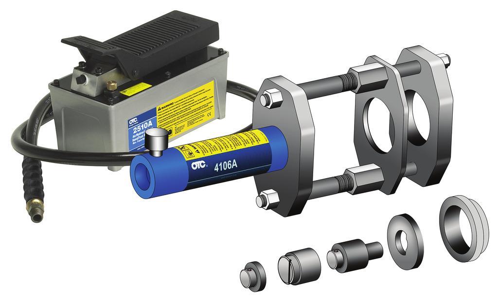
19 Parts List Item No. Part No. Qty. Description Hex Nut Kit (contains four nuts) Threaded Rod Cylinder Mounting Plate Clamping Nut Clamping Plate Head Plate A 1 Hydraulic Cylinder (25 Ton) Saddle Pin Alignment Tool Bushing Support Warning Decal (not shown) Warranty / Authorized Service Center List (not shown) Hose Assembly (4247 only; not shown) 2510A 1 Air / Hydraulic Pump (4247 only; not shown) Hose Half Coupler (4247 only; not shown) 17
20 Kits The chart below outlines the Hendrickson Suspension Tool packages and Kits available for specific Hendrickson applications. If you currently own one tool package, consider purchasing adapter kits for other specific applications. Hendrickson Tool Package Part No. No. 2510A Air/Hyd. Pump (w/ hose & coupler) No Bare Tool Hendrickson Kits available No (Volvo, Navistar, and Paccar) No (Comfort Air, Primaxx EX, and FCCC V-Ride) No (AIRTEK NXT [rear bushing only]) 4246 Tool Packages include items 4274 marked w/

21 Inspection and Maintenance CAUTION: To prevent personal injury, Only qualified personnel shall perform inspections to this Hendrickson Rear Suspension Bushing Tool. Before each use, an approved inspector must inspect the suspension bushing tool for bends, cracks, dents, elongated holes, or missing hardware. If damage is found, discontinue use. Use only those repair parts called out in the parts list in this document. Items found in the parts list have been carefully tested and selected by OTC. Maintenance To prevent contamination from entering the hydraulic system and damaging the cylinder, keep the cylinder clean. When the cylinder is not in use, keep the piston rod fully retracted and stored upside down. Use protective covers on disconnected quick couplers. Disposal At the end of its useful life, dispose of the suspension bushing tool according to federal, state, and local regulations. Order replacement parts at OTCparts.com This document contains product parts lists and information regarding operation and maintenance. Items listed in the parts list have been carefully tested and selected by OTC. Therefore, use only OTC replacement parts. Product questions may be directed to the OTC Technical Service Department at (800)
22 655 Eisenhower Drive Owatonna, MN USA Phone: (507) Tech. Serv.: (800) Fax: (800) Order Entry: (800) Fax: (800) International Sales: (507) Fax: (507) Bosch Automotive Service Solutions Inc. Form No Rev. C, June 12, 2018
Rear Suspension Bushing Remover/Installer
 655 EISENHOWER DRIVE OWATONNA, MN 55060-0995 USA PHONE: (507) 455-7000 TECH. SERV.: (800) 533-6127 FAX: (800) 955-8329 ORDER ENTRY: (800) 533-6127 FAX: (800) 283-8665 INTERNATIONAL SALES: (507) 455-7223
Hydraulic Hub Grappler Kit
 655 EISENHOWER DRIVE OWATONNA, MN 55060-0995 USA PHONE: (507) 455-7000 TECH. SERV.: (800) 533-6127 FAX: (800) 955-8329 ORDER ENTRY: (800) 533-6127 FAX: (800) 283-8665 INTERNATIONAL SALES: (507) 455-7223
Component for OTC No or No. 1750A
 655 Eisenhower Drive Owatonna, MN 55060 USA Phone: (507) 455-7000 Tech. Serv.: (800) 533-6127 Fax: (800) 955-8329 Order Entry: (800) 533-6127 Fax: (800) 283-8665 International Sales: (507) 455-7223 Fax:
3-Stage Under Axle Jack Weight: 69.5 kg (153 lbs.)
") 655 Eisenhower Drive Owatonna, MN 55060-0995 USA Phone: (507) 455-7000 Tech. Serv.: (00) 533-627 Fax: (00) 955-329 Order Entry: (00) 533-627 Fax: (00) 23-665 International Sales: (507) 455-7223 Fax: (507)
655 Eisenhower Drive Owatonna, MN 55060-0995 USA Phone: (507) 455-7000 Tech. Serv.: (00) 533-627 Fax: (00) 955-329 Order Entry: (00) 533-627 Fax: (00) 23-665 International Sales: (507) 455-7223 Fax: (507)
Air / Hydraulic Pump
 Form No. 538016 Parts List & Operating Instructions for: 2510A Original Instructions Air / Hydraulic Pump Maximum Capacity: 690 bar (10,000 psi) Description: The 2510A air/hydraulic pump is designed to
Collision Repair Set. Form No No. 1517A 4-Ton Set. No. 1519A 10-Ton Set. Parts List & Operating Instructions for: 1519A. Part No. Item No.
 SPX Corporation 655 Eisenhower Drive Owatonna, MN 55060-0995 USA Phone: (507) 455-7000 Tech. Serv.: (800) 533-6127 Fax: (800) 955-8329 Order Entry: (800) 533-6127 Fax: (800) 283-8665 International Sales:
Component for OTC No or No. 1750A Engine Mounting Adapter
 655 EISENHOWER DRIVE OWATONNA, MN 55060-0995 USA PHONE: (507) 455-7000 TECH. SERV.: (800) 533-6127 FAX: (800) 955-8329 ORDER ENTRY: (800) 533-6127 FAX: (800) 283-8665 INTERNATIONAL SALES: (507) 455-7223
High Lift Transmission Jack Max. Capacity: kg (1,000 lbs.)
") 655 EISENHOWER DRIVE OWATONNA, MN 55060-0995 USA PHONE: (507) 455-7000 TECH. SERV.: (800) 533-6127 FAX: (800) 955-8329 ORDER ENTRY: (800) 533-6127 FAX: (800) 283-8665 INTERNATIONAL SALES: (507) 455-7223
655 EISENHOWER DRIVE OWATONNA, MN 55060-0995 USA PHONE: (507) 455-7000 TECH. SERV.: (800) 533-6127 FAX: (800) 955-8329 ORDER ENTRY: (800) 533-6127 FAX: (800) 283-8665 INTERNATIONAL SALES: (507) 455-7223
Tire Bead Seater. Explanation of Safety Signal Words. The safety signal word designates the degree or level of hazard seriousness.
 Form No. 563999 Parts List & Operating Instructions for: 5702 Original Instructions Tire Bead Seater Application: Seats tubeless tires in a wide range of sizes. For example, small ATVs, passenger cars
Operating instructions Form no safety definitions
 Operating instructions Form no. 1000437 safety definitions safety symbols are used to identify any action or lack of action that can cause personal injury. Your reading and understanding of these safety
OPERATOR S MANUAL Model 60010
 OPERATOR S MANUAL Model 60010 10- TON SNAP LOCK PORTA POWER SET W/ WHEELED CASE PROFESSIONAL HYDRAULIC JACKS 1531 W. Mohawk Drive Phone 715-453-9602 Customer Service 800-995-2250 Tomahawk, WI 54487 Fax
Air / Hydraulic Pump Instructions. CAUTION: Read and Understand These Operating, Servicing, and Safety Instructions, Before Using This Machine.
 Air / Hydraulic Pump Instructions CAUTION: Read and Understand These Operating, Servicing, and Safety Instructions, Before Using This Machine. 1-800-467-2464 10 Cooperative Way Wright City, MO 63390 P.O.
Operating, Servicing, and Safety Manual Model # Hydraulic Bender
 Operating, Servicing, and Safety Manual Model # 900 90 Hydraulic Bender CAUTION: Read and Understand These Operating, Servicing, and Safety Instructions, Before Using This Machine. 1-800-467-2464 10 Cooperative
TWO-STAGE HYDRAULIC PUMP. RWP55-IBT-Air
 ORIGINAL INSTRUCTIONS Form No.1000458 5 SPX Corporation 5885 11th Street Rockford, IL 61109-3699 USA Tech. Services: (800) 477-8326 Fax: (800) 765-8326 Order Entry: (800) 541-1418 Fax: (800) 288-7031 Internet
WCI-20 Power-Pak Coldwork Hydraulic Power Supply Rev B
 WCI-20 Power-Pak Coldwork Hydraulic Power Supply Rev B OM-PS-9303-2 Seattle, Washington WCI-20 Power Pak Manual Table of Contents Section 1 Introduction 1.1 Introduction... 1 1.2 Safety Precautions...
Low Lift Transmission Jack
 655 Eisenhower Drive Owatonna, MN 55060 USA Phone: (507) 455-7000 Tech. Serv.: (800) 533-6127 Fax: (800) 955-8329 Order Entry: (800) 533-6127 Fax: (800) 283-8665 International Sales: (507) 455-7223 Fax:
Instruction Manual. Maximum Operating Pressure 700 bar
 Remote Hydraulic Cutter Model HC-120R Maximum Operating Pressure 700 bar ABSOLUTE EQUIPMENT PTY LTD 2/186 Granite Street, GEEBUNG QLD 4034 Australia sales@absoluteequipment.com.au Phone: +61 7 3865 4006
Instruction Manual. Double Acting Hydraulic, Hollow Piston Cylinders RHD Series. Maximum Operating Pressure 700 bar
 Double Acting Hydraulic, Hollow Piston Cylinders RHD Series Maximum Operating Pressure 700 bar ABSOLUTE EQUIPMENT PTY LTD 2/186 Granite Street, GEEBUNG QLD 4034 Australia sales@absoluteequipment.com.au
Air / Hydraulic Under Axle Jack
 655 Eisenhower Drive Owatonna, MN 55060-0995 USA Phone: (507) 455-7000 Tech. Serv.: (800) 533-6127 Fax: (800) 955-8329 Order Entry: (800) 533-6127 Fax: (800) 283-8665 International Sales: (507) 455-7223
Racing Jack Max. Capacity: 3,000 lbs. (1,361 kg)
") R SPX Corporation 655 Eisenhower Drive Owatonna, MN 55060-0995 USA Phone: (507) 455-7000 Tech. Serv.: (800) 533-6127 Fax: (800) 955-8329 Order Entry: (800) 533-6127 Fax: (800) 283-8665 International Sales:
R SPX Corporation 655 Eisenhower Drive Owatonna, MN 55060-0995 USA Phone: (507) 455-7000 Tech. Serv.: (800) 533-6127 Fax: (800) 955-8329 Order Entry: (800) 533-6127 Fax: (800) 283-8665 International Sales:
Air / Hydraulic Floor Service Jack
 SPX Corporation 655 Eisenhower Drive Owatonna, MN 55060-0995 USA Phone: (507) 455-7000 Tech. Serv.: (800) 533-6127 Fax: (800) 955-8329 Order Entry: (800) 533-6127 Fax: (800) 283-8665 International Sales:
Instruction Manual. Single Acting, Pancake, Locking Collar Hydraulic Cylinders RPLC Series. Maximum Operating Pressure 700 bar
 Single Acting, Pancake, Locking Collar Hydraulic Cylinders RPLC Series Maximum Operating Pressure 700 bar ABSOLUTE EQUIPMENT PTY LTD 2/186 Granite Street, GEEBUNG QLD 4034 Australia sales@absoluteequipment.com.au
Motorcycle/ATV Lift. Max. Capacity: 1,500 lbs. Parts List
 SPX Corporation 655 Eisenhower Drive Owatonna, MN 55060-0995 USA Phone: (507) 55-7000 Tech. Serv.: (800) 533-627 Fax: (800) 955-89 Order Entry: (800) 533-627 Fax: (800) 283-8665 International Sales: (507)
MANUAL PALLET VALVE # Manifold Mount Outlet Port # /16-20 UNF SAE-4 Outlet Port # /4 NPT Outlet Port Max. Capacity: 5,000 PSI
 Form No. 102963 SPX Corporation 5885 11th Street Rockford, IL 61109-3699 USA Internet Address: http://www.hytec.com Tech. Services: (800) 477-8326 Fax: (800) 765-8326 Order Entry: (800) 541-1418 Fax: (800)
Air / Hydraulic Floor Service Jack
 655 Eisenhower Drive Owatonna, MN 55060 USA Phone: (507) 455-7000 Tech. Serv.: (800) 533-6127 Fax: (800) 955-8329 Order Entry: (800) 533-6127 Fax: (800) 283-8665 International Sales: (507) 455-7223 Fax:
Instruction Manual. Single Acting Hydraulic Aluminium Pull Cylinders RAP Series. Maximum Operating Pressure 700 bar
 Single Acting Hydraulic Aluminium Pull Cylinders RAP Series Maximum Operating Pressure 700 bar ABSOLUTE EQUIPMENT PTY LTD 2/186 Granite Street, GEEBUNG QLD 4034 Australia sales@absoluteequipment.com.au
Air Assist Bottle Jack Max. Capacity: 12 Tons (4313C) & 20 Tons (4321C) Operating Range: psi
 & 20 Tons (4321C) Operating Range: psi") R SPX Division 655 Eisenhower Drive Owatonna MN 55060 Phone: (507) 455-7000 Tech. Serv.: (800) 533-6127 Fax: (800) 955-8329 Order Entry: (800) 533-6127 Fax: (800) 283-8665 International Sales: (507) 455-7223
R SPX Division 655 Eisenhower Drive Owatonna MN 55060 Phone: (507) 455-7000 Tech. Serv.: (800) 533-6127 Fax: (800) 955-8329 Order Entry: (800) 533-6127 Fax: (800) 283-8665 International Sales: (507) 455-7223
Instruction Manual. Maximum Operating Pressure 510 bar
 Single Speed Diesel Power Unit Model HPD11 Maximum Operating Pressure 510 bar ABSOLUTE EQUIPMENT PTY LTD 2/186 Granite Street, GEEBUNG QLD 4034 Australia sales@absoluteequipment.com.au Phone: +61 7 3865
Forklift Jack. Scissors Max. Capacity: 4 ton Scissors Low Height: 2-5/32 in. (55 mm) Scissors High Height: 17-29/32 in. (455 mm)
 Scissors High Height: 17-29/32 in. (455 mm)") 655 Eisenhower Drive Owatonna, MN 55060 USA Phone: (507) 455-7000 Tech. Serv.: (800) 533-6127 Fax: (800) 955-8329 Order Entry: (800) 533-6127 Fax: (800) 283-8665 International Sales: (507) 455-7223 Fax:
655 Eisenhower Drive Owatonna, MN 55060 USA Phone: (507) 455-7000 Tech. Serv.: (800) 533-6127 Fax: (800) 955-8329 Order Entry: (800) 533-6127 Fax: (800) 283-8665 International Sales: (507) 455-7223 Fax:
Bench Press. Form No Parts List & Operating Instructions for: Max. Capacity: 16.5 Ton
 655 Eisenhower Drive Owatonna, MN 55060 USA Phone: (507) 455-7000 Tech. Serv.: (800) 533-627 Fax: (800) 955-8329 Order Entry: (800) 533-627 Fax: (800) 283-8665 International Sales: (507) 455-7223 Fax:
Instruction Manual. Single Acting, High Tonnage, Low Height Cylinders RSH Series. Maximum Operating Pressure 700 bar
 Single Acting, High Tonnage, Low Height Cylinders RSH Series Maximum Operating Pressure 700 bar ABSOLUTE EQUIPMENT PTY LTD 2/186 Granite Street, GEEBUNG QLD 4034 Australia sales@absoluteequipment.com.au
XP-AIR Multi-Port Power Pack Operation and Maintenance Manual
 XP-AIR Multi-Port Power Pack Operation and Maintenance Manual http://www.torsionx.com Safety Guide To use the XP-AIR Multi-Port Power Pack safely you must follow correct operation guidelines and inspect
Clevis Plunger & Base Instruction Manual
 MODELS: CED09 & CED16 SFA Companies 10939 N. Pomona Ave. Kansas City, MO 64153 Tel: 888-332-6419 - Fax: 816-448-2142 E-mail: sales@bvahydraulics.com Website: www.bvahydraulics.com CED09-M0_102017 Clevis
Manifold w/ Needle Valve Instruction Manual
 MODELS: MFC2 & MFC4 Manifold w/ Needle Valve Instruction Manual SFA Companies 10939 N. Pomona Ave. Kansas City, MO 64153 Tel: 888-332-6419 - Fax: 816-448-2142 E-mail: sales@bvahydraulics.com Website: www.bvahydraulics.com
Operating Instructions & Parts Manual
 Porto-Power Blackhawk Automotive is a licensed trademark Flat Body Rams Operating Instructions & Parts Manual Model Number B65139 (Ram w/ magnetic adapters) B65140 (Ram only) Capacity 5 Ton 4 Ton Model
Bench Press Max Capacity: 16.5 Ton
 R SPX Corporation 655 Eisenhower Drive Owatonna, MN 55060-0995 USA Phone: (507) 455-7000 Tech. Serv.: (800) 533-627 Fax: (800) 955-8329 Order Entry: (800) 533-627 Fax: (800) 283-8665 International Sales:
Instruction Manual. Single Acting, Aluminium, Locking Collar Hydraulic Cylinders ARSLC Series. Maximum Operating Pressure 700 bar
 Single Acting, Aluminium, Locking Collar Hydraulic Cylinders ARSLC Series Maximum Operating Pressure 700 bar ABSOLUTE EQUIPMENT PTY LTD 2/186 Granite Street, GEEBUNG QLD 4034 Australia sales@absoluteequipment.com.au
Gauge Adapter Instruction Manual
 Instruction Manual MODELS: CF3812, CF3812E, CF3814 & CF4514 CF3812-M1_092017! This is the safety alert symbol. It is used to alert you to potential personal injury hazards. Obey all safety messages that
Instruction Manual. 08 Series Auto 2 Speed Electric Power Units Model PEM8414 & PEM8424. Maximum Operating Pressure 700 bar
 08 Series Auto 2 Speed Electric Power Units Model PEM8414 & PEM8424 PEM8414 PEM8424 Maximum Operating Pressure 700 bar ABSOLUTE EQUIPMENT PTY LTD 2/186 Granite Street, GEEBUNG QLD 4034 Australia sales@absoluteequipment.com.au
XP-115 Multi-Port Power Pack Operation and Maintenance Manual
 XP-115 Multi-Port Power Pack Operation and Maintenance Manual http://www.torsionx.com Safety Guide To use the XP-115 Multi-Port Power Pack safely you must follow correct operation guidelines and inspect
Service Jacks. No. 1503A Max. Capacity: 2-1/2 Tons No. 1504A Max. Capacity: 3 Tons. Service Jack Item List
 SPX Corporation 655 Eisenhower Drive Owatonna, MN 55060-0995 USA Phone: (507) 455-7000 Tech. Serv.: (800) 533-6127 Fax: (800) 955-8329 Order Entry: (800) 533-6127 Fax: (800) 283-8665 International Sales:
High Lift Transmission Jack
 655 Eisenhower Drive Owatonna, MN 55060-0995 USA Phone: (507) 455-7000 Tech. Serv.: (800) 533-6127 Fax: (800) 955-8329 Order Entry: (800) 533-6127 Fax: (800) 283-8665 International Sales: (507) 455-7223
Air Assist Bottle Jack Max. Capacity: 12 Tons (4313C) & 20 Tons (4321C) Operating Range: psi
 & 20 Tons (4321C) Operating Range: psi") Form No. 545742 Parts List and Operating Instructions for: 4313C 4321C Air Assist Bottle Jack Max. Capacity: 12 Tons (4313C) & 20 Tons (4321C) Operating Range: 40 150 psi 45 44 43 42 41 40 39 22 1 37 28
Form No. 545742 Parts List and Operating Instructions for: 4313C 4321C Air Assist Bottle Jack Max. Capacity: 12 Tons (4313C) & 20 Tons (4321C) Operating Range: 40 150 psi 45 44 43 42 41 40 39 22 1 37 28
Service Jack. Form No Parts List & Operating Instructions 1510B. Max. Capacity: 5 and 10 Tons. 1 of 3. Sheet No. Issue Date: Rev.
 SPX Corporation 655 Eisenhower Drive Owatonna, MN 55060-0995 USA Phone: (507) 455-7000 Tech. Serv.: (800) 533-6127 Fax: (800) 955-8329 Order Entry: (800) 533-6127 Fax: (800) 283-8665 International Sales:
KLW4000D Multi-Port Power Pack
 KLW4000D Multi-Port Power Pack Operation and Maintenance Manual Safety Guide To use the KLW4000DMulti-Port Power Pack safely you must follow correct operation guidelines and inspect the equipment regularly.
High Lift Transmission Jack
 655 Eisenhower Drive Owatonna, MN 55060 USA Phone: (507) 455-7000 Tech. Serv.: (800) 533-6127 Fax: (800) 955-8329 Order Entry: (800) 533-6127 Fax: (800) 283-8665 International Sales: (507) 455-7223 Fax:
High Lift Transmission Jack
 SPX Corporation 655 Eisenhower Drive Owatonna, MN 55060-0995 USA Phone: (507) 455-7000 Tech. Serv.: (800) 533-6127 Fax: (800) 955-8329 Order Entry: (507) 455-1480 Fax: (800) 283-8665 International Sales:
Operating, Servicing, and Safety Manual Model # Hydraulic Bender
 - 1 - Operating, Servicing, and Safety Manual Model # 2500 180 Hydraulic Bender CAUTION: Read and Understand These Operating, Servicing, and Safety Instructions, Before Using This Machine. 1-800-467-2464
Operating Instructions for: PE10 Series. Electric-Powered 10 Series Hydraulic Pump SPX
 Operating Instructions for: PE10 Series Electric-Powered 10 Series Hydraulic Pump Table of Contents Description............................................................2 PE10-Series Electric / Hydraulic
Hand Pump Instruction Manual
 MODEL: ZP601S Hand Pump Instruction Manual SFA Companies 10939 N. Pomona Ave. Kansas City, MO 64153 Tel: 888-332-6419 * Fax: 816-891-6599 E-mail: sales@bvahydraulics.com Website: www.bvahydraulics.com
IN-LINE HYDRAULIC FLOW TESTER
 SPX Corporation 5885 11th Street Rockford, IL 61109-3699 USA Internet Address: http://www.powerteam.com Tech. Services: (800) 477-8326 Fax: (800) 765-8326 Order Entry: (800) 541-1418 Fax: (800) 288-7031
Hydraulic Transmission Jack, Telescopic
 Operating Instructions & Parts Manual Hydraulic Transmission Jack, Telescopic Model 4000 400 (Air Operated) Capacity 000 lbs. 000 lbs. Model 4000 Model 400 U.S. Patent No. 6,02,377! This is the safety
Hydraulic Spreader. Operating Instructions & Parts Manual
 Porto-Power Blackhawk Automotive is a licensed trademark Hydraulic Spreader Operating Instructions & Parts Manual Model Numbers B65123 B65145 B65123 B65145 This is the safety alert symbol. It is used to
GM Ball Joint Adapter Kit
 655 Eisenhower Drive Owatonna, MN 55060 USA Phone: (507) 455-7000 Tech. Serv.: (800) 533-6127 Fax: (800) 955-8329 Order Entry: (800) 533-6127 Fax: (800) 283-8665 International Sales: (507) 455-7223 Fax:
Portable Two-Stage Under Axle Jack Max. Capacity: First Stage: 27.5 Tons Second Stage: 11 Tons. Safety Precautions
 SPX Corporation Eisenhower Drive Owatonna, MN 00-0 USA Phone: (07) -7000 Tech. Serv.: (00) -7 Fax: (00) - Order Entry: (00) -7 Fax: (00) - International Sales: (07) -7 Fax: (07) -70 Form No. Parts List
Honda, Acura Ball Joint Adapter Kit
 655 Eisenhower Drive Owatonna, MN 55060 USA Phone: (507) 455-7000 Tech. Serv.: (800) 533-6127 Fax: (800) 955-8329 Order Entry: (800) 533-6127 Fax: (800) 283-8665 International Sales: (507) 455-7223 Fax:
MODEL 890 / 892 POWER POST 10 TON CAPACITY
 MODEL 890 / 892 POWER POST 10 TON CAPACITY Jackco Transnational Inc. LIMITED ONE YEAR WARRANTY Jackco Transnational Inc. warrants all Jackco equipment and tools to the original purchaser against any manufacturing
Rams. Operating Instructions & Parts Manual. Model Number B65141 B65553 B65555 B65441 B65446 B65449 B65746
 Porto-Power Blackhawk Automotive is a licensed trademark Rams Operating Instructions & Parts Manual Model Number B6141 B6 B6 B6441 B6446 B6449 B6746 Capacity Ton Ton Ton 10 Ton 10 Ton 10 Ton Ton SFA Companies
Short Rams. Operating Instructions & Parts Manual. Model Number B65141 B Capacity 2 Ton 10 Ton
 Porto-Power Blackhawk Automotive is a licensed trademark Short Rams Operating Instructions & Parts Manual Model Number B65141 B65441 Capacity 2 Ton 10 Ton SFA Companies 2004 10939 N. Pomona Ave. Kansas
Operating Instructions & Parts Manual. Model HW93300 shown
 Shop Press Operating Instructions & Parts Manual Model Number HW93300,(hand operated pump) HW93301 (air operated pump) HW93302,(electric pump) HW93305,(double acting, hand operated pump) HW93306,(double
Rams. Operating Instructions & Parts Manual. Model Number B65142 B65150 B65442 B65444 B65452 B Capacity 4 Ton 4 Ton 10 Ton 10 Ton 10 Ton 25 Ton
 Porto-Power Blackhawk Automotive is a licensed trademark Rams Operating Instructions & Parts Manual Model Number B65142 B65150 B65442 B65444 B65452 B65740 Capacity 4 Ton 4 Ton 10 Ton 10 Ton 10 Ton 25 Ton
2 TON CAPACITY PROFESSIONAL SERIES ALUMINUM JACK OWNER'S MANUAL SPECIFICATIONS
 80006 OWNER'S MANUAL CONTENTS: Page 1 Specifications 2 Warning Information 3 Setup, Operating and Preventative Maintenance 4 Troubleshooting 5 Maintenance 6 Exploded View Drawing and Replacement Parts
ABSOLUTE EQUIPMENT PTY LTD
 Manual Hydraulic Toe Jack Model DTJ Series ABSOLUTE EQUIPMENT PTY LTD 2/186 Granite Street, GEEBUNG QLD 4034 Australia sales@absoluteequipment.com.au Phone: +61 7 3865 4006 Fax: +61 7 3102 6288 This is
ABSOLUTE EQUIPMENT PTY LTD
 Manual Hydraulic Toe Jack Model DTJ Series ABSOLUTE EQUIPMENT PTY LTD 2/186 Granite Street, GEEBUNG QLD 4034 Australia sales@absoluteequipment.com.au Phone: +61 7 3865 4006 Fax: +61 7 3102 6288 This is
Hyundai, Infiniti, Nissan, Saab, Toyota Ball Joint Adapter Kit
 655 Eisenhower Drive Owatonna, MN 55060 USA Phone: (507) 455-7000 Tech. Serv.: (800) 533-6127 Fax: (800) 955-8329 Order Entry: (800) 533-6127 Fax: (800) 283-8665 International Sales: (507) 455-7223 Fax:
Under Axle Jack Max. Capacity: 25 Tons
 SPX Corporation 655 Eisenhower Drive Owatonna, MN 55060-0995 USA Phone: (507) 455-7000 Tech. Serv.: (800) 533-6127 Fax: (800) 955-8329 Order Entry: (800) 533-6127 Fax: (800) 283-8665 International Sales:
Hand Pump Instruction Manual
 MODELS: P350, P1000, & P1000AD Instruction Manual P350-M0_092017 Maximum Operating Pressure 10,000 PSI Model P350 Models P1000 &P1000AD! This is the safety alert symbol. It is used to alert you to potential
Long Chassis Hydraulic Service Jacks
 Long Chassis Hydraulic Service Jacks Operating Instructions & Parts Manual Model Number Atd-7390 Atd-7391 Capacity 5 Ton 10 Ton Atd Tools Inc. 160 Enterprise Drive, Wentzville MO 63385 Printed in China
Hydraulic Transmission Jacks
 Hydraulic Transmission Jacks Operating Instructions & Parts Manual Model Number Atd-7435 Atd-7436 Atd-7437 Capacity 1100 Lb. 2000 Lb. 3000 Lb. Model Atd-7435 Model Atd-7436 Model Atd-7437 Atd Tools Inc.
Hand Pump Instruction Manual
 Hand Pump Instruction Manual MODELS: P101, P101S, P301, P301M, P4301 & P4301M P101-M0_11018 Maximum Operating Pressure 10,000 PSI Models P101 & P101S Models P301 & P4301 Model P301M & P4301M! This is the
jegs.com. Installation Instructions for Ton Aluminum Floor Jack
 Installation Instructions for 80077 3-Ton Aluminum Floor Jack Contents: Specifications Warning Information Setup and Operating Instructions Preventive Maintenance and Troubleshooting Hydraulic Maintenance
High Tonnage Single Acting Cylinders Instruction Manual
 MODELS: HG30002, HG30006, HG3002 HG4002 HG50002, HG50006, HG5002 HG30002-M0_02206 Instruction Manual - 300 Ton capacity - 400 Ton capacity - 500 Ton capacity Maximum Operating Pressure 0,000 PSI This is
6602LP CAPACITY: 2 TON LOW RIDER SERVICE JACK
 CONTENTS: Page 1 Specifications 2 Warning Information 3 Setup Instructions 4 Operating Instructions, Preventative Maintenance, Inspection and Proper Storage 5 Hydraulic Jack Maintenance Guide and Regular
Porta-Punch Manual
 Porta-Punch Manual 474 E. 05th Street Cleveland, OH 4408-378 (26) 68-7400 Fax (26) 68-7009 www.clevelandsteeltool.com E-mail: sales@clevelandsteeltool.com 800-446-4402 TABLE OF CONTENTS Page General Information...
PE39 Series Compact Torque Wrench Pump
 SPX Bolting Systems Unit 4, Wansbeck Business Park Rotary Parkway Ashington Northumberland NE63 8QW spxboltingsystems.com Tel: +44 (0) 1670 850580 Fax: +44 (0) 1670 850655 Operating Instructions for: PE39PED1BPR
WARNING SPECIFICATIONS MODEL # A 1-1/2 TON TRANSMISSION JACK. Manufactured to comply with the ASME PASE-2014 Safety Standard.
 MODEL # 791-7180 A 1-1/2 TON TRANSMISSION JACK BEFORE USING THIS DEVICE, READ THIS MANUAL COMPLETELY AND THOROUGHLY, UNDERSTAND ITS OPERATING PROCEDURES, SAFETY S AND MAINTENANCE REQUIREMENTS. It is the
CONTENTS: 5740AH - 40 Ton Air/Hydraulic Shop Press 5750AH - 50 Ton Air/Hydraulic Shop Press OWNER'S MANUAL
 OWNER'S MANUAL CONTENTS: Page 1 Specifications 2 Safety Information and Warranty Information 3 Parts List 4-6 Assembly Instructions 7 Pump and Ram Assembly Instructions 8 Procedure for Bleeding Air 9 Pump
Hydraulic Wheel Dolly
 Hydraulic Wheel Dolly Operating Instructions & Parts Manual Model Number HW93766 Capacity 3/4 Ton Made in the U.S.A. This is the safety alert symbol. It is used to alert you to potential personal injury
Hydraulic Spreader Instruction Manual
 Hydraulic Spreader Instruction Manual MODEL NUMBERS: SR05, SR07 & SR10 SFA Companies 10939 N. Pomona Ave. Kansas City, MO 64153 Tel: 888-332-6419 * Fax: 816-448-2142 E-mail: sales@bvahydraulics.com Website:
SPECIFICATIONS CONTENTS: Warning Information. Operating Instructions Preventative Maintenance and Troubleshooting
 Model 3322 22 Ton Air/Hydraulic Truck Axle Jack OWNER'S MANUAL CONTENTS: Page 1 Page 2 Page 3-4 Page 4-5 Page 5 Page 6 Page 7 Page 8 Specifications Warning Information Assembly Operating Instructions Preventative
Mini Jacks Instruction Manual
 J11050-M0_062017 Instruction Manual MODELS: J11050, J11055-5 Ton Capacity J11100-10 Ton Capacity J11200-20 Ton Capacity This is the safety alert symbol. It is used to alert you to potential personal injury
Premium Supply. Direct Push. Models PCK-3530-DP PCK DP PCK-530-DP. Operator s Manual and Installation Instructions
 Direct Push Models PCK-3530-DP PCK-3530-2DP PCK-530-DP Operator s Manual and Installation Instructions Premium Supply 2038 West Interstate 30 866-934-0777 Proud members of: and June 20, 2018 Table of Contents
Hydraulic Gear Puller Instruction Manual
 + HGP053-M0_052015 Hydraulic Gear Puller Instruction Manual MODELS: HGP053 HGP103 HGP153 HGP253 HGP503-5 Ton Capacity -10 Ton Capacity -15 Ton Capacity -25 Ton Capacity -50 Ton Capacity SFA Companies 10939
High Tonnage Double Acting Cylinders Instruction Manual
 HDG15002-M0_092015 High Tonnage Double Acting Cylinders Instruction Manual MODELS: HDG15002, HDG15004, HDG15006, HDG15008, - 150 Ton Capacity HDG15010, HDG15012 HDG20002, HDG20004, HDG20006, HDG20008,
Single Acting Aluminum Cylinders Instruction Manual
 MODELS: HU2002T, HU2004T, HU2006T HU3002T, HU3004T, HU3006T HU5002T, HU5004T, HU5006T, HU5010T Single Acting Aluminum Cylinders Instruction Manual - 20 Ton Capacity - 30 Ton Capacity - 50 Ton Capacity
Air Actuated Hydraulic Bottle Jacks
 Air Actuated Hydraulic Bottle Jacks Operating Instructions & Parts Manual Model Number Atd-7412 Atd-7420 Capacity 12 Ton 20 Ton Atd Tools Inc. 160 Enterprise Drive, Wentzville MO 63385 Printed in China
Gas Engine Pumps Instruction Manual
 MODELS: PG70M3N05 & PG70M4N05 Gas Engine Pumps Instruction Manual SFA Companies 10939 N. Pomona Ave. Kansas City, MO 64153 Tel: 888-332-6419 * Fax: 816-448-2142 E-mail: sales@bvahydraulics.com Website:
Air Hydraulic Pumps Instruction Manual
 MODELS: PA3801-HP12 Air Hydraulic Pumps Instruction Manual SFA Companies 10939 N. Pomona Ave. Kansas City, MO 64153 Tel: 888-332-6419 * Fax: 816-891-6599 E-mail: sales@bvahydraulics.com Website: www.bvahydraulics.com
Heavy Duty Engine Cranes
 Heavy Duty Engine Cranes Operating Instructions & Parts Manual Model Number Atd-7484 Atd-7485 (Foldable Legs) Capacity 2 Ton 2 Ton Model Atd-7484 Model Atd-7485 Atd Tools Inc. 160 Enterprise Drive, Wentzville,
6722 Rev. A CAPACITY: 22 TON TRUCK AXLE JACK WITH AIR RETURN
 CONTENTS: Page Specifications 2 Warning Information Setup Instructions and Operating Instructions 4 Preventative Maintenance, Inspection and Proper Storage 5 Troubleshooting, Owner/User Responsibility
Heavy Duty Bottle Jacks
 Heavy Duty Bottle Jacks Models: 10300 & 10500 10300 10500! This is the safety alert symbol. It is used to alert you to potential personal injury hazards. Obey all safety messages that follow this symbol
Low Profile Service Jack
 Low Profile Service Jack Model GMG29031 Capacity 3 Ton U.S. Patent No. 6,199,379! This is the safety alert symbol. It is used to alert you to potential personal injury hazards. Obey all safety messages
Fast Lift Service Jack, Low Profile
 Blackhawk Automotive is a Licensed Trade Mark Made by SFA Companies, Kansas City, MO Fast Lift Service Jack, Low Profile Operating Instructions & Parts Manual Model BH6023B Capacity 2 Ton! U.S. Patent
HYDRAULIC PUMP. INSTALLATION, OPERATION, & MAINTENANCE MANUAL MAINTENANCE MANUAL #: MM-HP Rev. A Page 1 of 12
 INSTALLATION, OPERATION, & #: MM-HP001 4-20-09 Rev. A Page 1 of 12 HYDRAULIC PUMP PART NUMBER HP46982ALSL & HP46982SL HYDRAULIC PUMP MM-HP001 Rev. A Page 2 of 12 Table of Contents 1.0 General Page 3 2.0
Hydraulic Long Jacks
 Operating Instructions & Parts Manual Hydraulic Long Jacks Model 44915 44930 44940 44980 44981C (Air option) Capacity 1-1/2 Ton 3 Ton 4 Ton 8 Ton 8 Ton Models 44915, 44930, 44940 & 44980 Model 44981C U.S.
Vehicle Lift System Max. Capacity: 10 Tons (Pair) at 150 PSI
 at 150 PSI") 655 Eisenhower Drive Owatonna, MN 55060 USA Phone: (507) 455-7000 Tech. Serv.: (800) 533-6127 Fax: (800) 955-8329 Order Entry: (800) 533-6127 Fax: (800) 283-8665 International Sales: (507) 455-7223 Fax:
655 Eisenhower Drive Owatonna, MN 55060 USA Phone: (507) 455-7000 Tech. Serv.: (800) 533-6127 Fax: (800) 955-8329 Order Entry: (800) 533-6127 Fax: (800) 283-8665 International Sales: (507) 455-7223 Fax:
High-Lift Wheel Dolly Max. Capacity: 1,500 lbs. (681 kg)
") 55 Eisenhower Drive Owatonna, MN 5500-0995 USA Phone: (507) 455-7000 Tech. Serv.: (800) 533-27 Fax: (800) 955-8329 Order Entry: (800) 533-27 Fax: (800) 283-85 International Sales: (507) 455-7223 Fax: (507)
55 Eisenhower Drive Owatonna, MN 5500-0995 USA Phone: (507) 455-7000 Tech. Serv.: (800) 533-27 Fax: (800) 955-8329 Order Entry: (800) 533-27 Fax: (800) 283-85 International Sales: (507) 455-7223 Fax: (507)
2 Speed Hydraulic Hand Pump
 Porto-Power Blackhawk Automotive is a licensed trademark 2 Speed Hydraulic Hand Pump Operating Instructions & Parts Manual B65122 B65421 SFA Companies 10939 N. Pomona Ave. Kansas City, MO 64153 816-891-6390
Pulling Post Kit Operating Instructions & Parts Manual
 Porto-Power Blackhawk Automotive is a licensed trademark Pulling Post Kit Operating Instructions & Parts Manual Model Number B93601A Items included: B93600A 10 Ton Pulling Post B65428 Air Pump with Hose
MODEL 25-OM-10-C & 25-OA-10-C HYDRAULIC BOOSTER
 SPX Corporation 5885 11th Street Rockford, IL 61109-3699 USA Internet Address: http://www.powerteam.com Tech. Services: (800) 477-8326 Fax: (800) 765-8326 Order Entry: (800) 541-1418 Fax: (800) 288-7031