Digital Multimeter AHMAD FOUAD ALWAN
|
|
|
- Oscar Crawford
- 5 years ago
- Views:
Transcription
1 Digital Multimeter AHMAD FOUAD ALWAN

2 What is a Digital Multimeter?


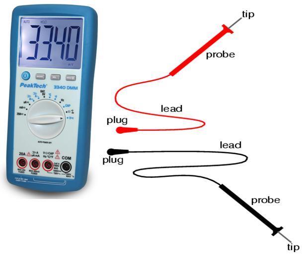
3 Test leads are used to connect the multimeter to the circuit to be tested.
4 1. To know how to use the Ammeter and how to read the measure. 2. To learn how to operate the Voltmeter and read the recorded voltage. 3. Have knowledge about measuring resistance using the Ohmmeter.
5 The voltmeter is used to measure the voltage potential across a component in an active circuit. It can be used to measure either DC or AC voltages, resistance, and current in an electric circuit.
6 How to measure voltage Ammeter use A digital multimeter measures AC / DC voltage, resistance, and current in an electric circuit. How to measure current Current is the measure of the rate of electron "flow" in a circuit. It is measured in the unit of the Ampere, simply called "Amp," (A).
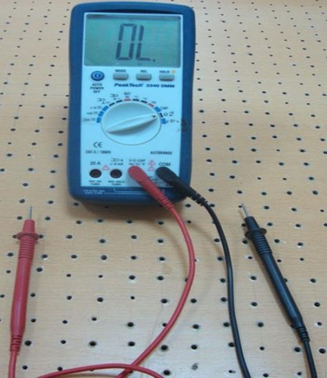
7
8 How to measure resistance Use of Ohm's Law
9 Take and the measure the voltage and resistance of a circuit, use the Ohm's Law equation to calculate circuit current. Compare this calculated figure with the measured figure for circuit current:
10 Taking the measured figures for voltage and current, use the Ohm's Law equation to calculate circuit resistance. Compare this calculated figure with the measured figure for circuit resistance: Taking the measured figures for resistance and current, use the Ohm's Law equation to calculate circuit voltage. Compare this calculated figure with the measured figure for circuit voltage:
11

12 1. LCD - Display Screen to show the measurements 2. Function / Range Selector Rotary Switch This rotary switch selects function and range needed. Each time the rotary switch is moved from OFF to a function setting, all LCD segments will turn on for one second. 3. COM - Terminal This is the negative (ground) input terminal for all measurement modes. Connection is made to it using the black test lead. 4. V/Ω/CAP/Hz/Temp. - Input Terminal This is the positive input terminal for all functions except current/capacitance measurements. Connection is made to it using the red test lead.
13 6. 20 A - Input Terminal This is the positive input terminal for current measurement (AC or DC) up to 20 A. Connection is made to it using the red test lead. 7. HOLD - Button Press HOLD-button to toggle in and out of the DATA-Hold mode. In the DATA-Hold mode, the "HOLD" annunciator is displayed and the last reading is frozen on the display. Press the HOLD-button again to exit and resume readings. To switch on or off the backlight, press HOLD-button for 2 sec. 8. REL - Δ - button When the REL- Δ button is pressed the present reading becomes the zero reading and all subsequent readings are displayed relative to this value. This function is cleared by pressing the REL- Δ button > 1 sec. which returns the meter to normal operation. 9. MODE - button For switching from AC/DC voltage ranges to current ranges and from resistance, diode test and continuity test. 10. ON/OFF button For switching the instrument on and off.
14 Connection of test leads The supplied test leads can be used for measurements up to 1000 V. High-voltage measurements should be done with care and in presence of a person, who is educated in first-aid. The maximum input voltage for this instrument is 1000 V DC or 700 V AC and to be on the safe side, these values mustn t be passed. The maximum voltage - difference between COMinput and earth is 500 V DC/AC eff. Higher voltage-differences may cause personal injury or damage of the unit.
15
16 There are many different functions to choose from on the function switch. The first is off. The meter should always be returned to this position when not in use. The V markings are for measuring DC and AC voltage The Ω marking is for measuring resistance. The A marking is for measuring current.

17 Measurements must only be made with the circuit power OFF. 1. Insert the black and red test lead into the COM and V/Ω/CAP/Hz/Temp. - Input terminal respectively. 2. Set the Rotary Selector Switch to the Ω - position. 3. Select the function by pressing the Mode - button. 4. Follow steps 1 and 3 as for resistance measurements.
18 1. Insert the black and red test lead into the COM and V/Ω/CAP/Hz/Temp.- input terminal respectively. 2. Set the Rotary Selector Switch to the Ω - position. 3. Select the *))) function by pressing the MODE - button. 4. Follow steps 1 and 3 as for resistance measurements. An audible tone will sound for resistance less than approx. 50 W. After all measurements are completed, disconnect the test leads from the circuit and from the multimeter input terminals. 5. The red lead should be connected to the anode and the black lead to the cathode. For a silicon diode, the typical forward voltage should be about 0,6 V.
19
20 Turn Power Off before connecting multimeter Break Circuit Place multimeter in series with circuit Select highest current setting, turn power on, and work your way down. Turn power off Disconnect multimeter. Reconnect Circuit
21
22 Power always has to be off. Component has to be removed from circuit. Start at lowest Ohm setting.
. 2. Connect the test leads to the capacitor. Observe polarity when measuring polarized capacitors. 3.")
23 Turn off power and discharge the capacitor before attempting a capacitance measurement. Use the DCV function to confirm that the capacitor is discharged. 1. Set the Function / Range switch to CAP (capacitance). 2. Connect the test leads to the capacitor. Observe polarity when measuring polarized capacitors. 3. Read the capacitance directly from the display. A shorted capacitor will indicate an over range. An open capacitor will indicate near zero on all ranges.


24 1. Set the Function / Range switch to Hz for frequency measurement. 2. Connect the red test lead to the V/Ω/CAP/Hz/Temp. - Input jack and the black test lead to the COM - jack. 3. Connect test leads to the point of measurement and read the frequency from the display.

25 1. Select the required temperature range, by turning the rotary selector switch either to C or F position. Connect the thermocouple adaptor to the V/Ω/CAP/Hz/Temp.- and COM input terminal. 2. Connect a type K thermocouple to the thermocouple input terminal on the thermocouple adaptor. 3. Place the thermocouple junction tip at the point where the temperature is to be measured. 4. For very high temperatures the multimeter must be kept far enough away from the source of temperature to avoid heat damage. At high temperatures, the life of the temperature probe will be reduced.
26 1. Insert the black test lead plug into the negative COM jack and the red test lead plug into the positive V jack. 2. Select the BAT 9V position using the function select switch. 3. Connect the red test lead to the positive side of the 9V battery and the black test lead to the negative side of the 9V battery. 4. Read the voltage in the display

27 When you connect the test probes to an AC outlet, do not turn the rotary selector switch to another range. It could damage the meter s internal components or injure you. Understanding Phantom readings in some DC and AC voltage ranges, when the test leads are not connected to any circuit, the display might show a phantom reading. This is normal. When you connect the test leads to a circuit, accurate reading appears. Before making any measurements always examine the instrument and accessories used with the instrument for damage, contamination (excessive dirt, grease, etc.) and defects. Examine the test leads for cracked or frayed insulation and make sure the lead plugs fit snugly into the instrument jacks. In any abnormal conditions exist do not attempt to make any measurements.
28 Insert the black and red test leads into the COM and V/Ω/ CAP/Hz/Temp.- input terminals respectively. Select the desired AC voltage range (V ~) or DC voltage range (V ). To avoid possible electric shock, instrument damage, do not take any voltage measurements if the voltage is above 1000 V DC / 700 V AC V DC and 700 V AC are the maximum voltages, that this instrument is designed to measure. The "COM" terminal potential should not exceed 500 V measured to ground

29 Connect the test lead tips in parallel with the circuit to be measured (e.g. across a load or power supply). Be careful not to touch any energized conductors. Note the reading. When all measurements are complete, disconnect the test leads from the circuit under test. Remove the leads from the multimeter. For DC voltage readings, the RED lead tip. Should be connected to the positive side of the circuit, the BLACK lead to the negative side. A minus (negative) sign on the left hand of the LCD will appear if the leads are connected the other way round.

30 These are made in series with the test circuit. All the current to be measured flows through the multimeter. 1. Insert the BLACK test lead in the COM input terminal. 2. For measuring currents less than 400 ma, connect the red test lead to the μa/ma input terminal. For measuring currents between 400 ma and 20 A connect RED test lead to the 20 A terminal. 3. Select the desired current range and select AC/DC by pressing MODE-button. 4. If the (20 A) range is selected then the (20 A) input terminal must be selected in step2. If the (μa, ma) ranges is selected the (ma) input terminal must be selected in step 2.

31 a. Do not attempt to measure currents in high energy circuits capable of delivering greater than 500 V. Since the fuse is rated at 250 V damage or injury could occur. The ma input terminal is protected by a 500 ma/250 V fast blow fuse. b. If a current greater than 20 A on the 20 A ranges or greater ranges flow, the fuse will blow causing an open circuit between the current measuring terminals.
32 To avoid electric shock, disconnect all the test probes before removing the fuse. Replace only with the same type of fuse. Not note remove the top cover. Service should be performed only by qualified personnel. For continued protection against fire or other hazard, replace only with fuse of the specified voltage and current ratings.
33 Press ON/OFF button to turn the meter off and disconnect the test probes. Remove the back cover by unscrewing the five screws and pulling off the meter s cover. Remove the blown fuse. Install the new fuse in the fuse compartment. Replace the cover and secure it with the screws. Do not operate your meter until the back cover is in place and fully closed.
99 Washington Street Melrose, MA Fax TestEquipmentDepot.com. Instruction Manual. Model 2831D 4 ½ Digit True RMS Digital Multimeter
 99 Washington Street Melrose, MA 02176 Fax 781-665-0780 TestEquipmentDepot.com Instruction Manual Model 2831D 4 ½ Digit True RMS Digital Multimeter 1 1. PRODUCT DESCRIPTION 1-1. Introduction Thank you
True RMS Autoranging Multimeter
 Owner's Manual True RMS Autoranging Multimeter Model No. 73754 CAUTION: Read, understand and follow Safety Rules and Operating Instructions in this manual before using this product. Safety Operation Maintenance
ASTROAI USER MANUAL DIGITAL MULTIMETER. NOTE: Fully read and understand this manual before using this instrument.
 ASTROAI USER MANUAL DIGITAL MULTIMETER NOTE: Fully read and understand this manual before using this instrument. WARNING: To avoid possible electric shock or personal injury, and to avoid possible damage
Autoranging Multimeter
 Owner's Manual Autoranging Multimeter Model No. 82334 CAUTION: Read, understand and follow Safety Rules and Operating Instructions in this manual before using this product. Safety Operation Maintenance
Autoranging Industrial Multimeter
 Owner's Manual Autoranging Industrial Multimeter Model No. 82005 CAUTION: Read, understand and follow Safety Rules and Operating Instructions in this manual before using this product. Safety Operation
Digital Multimeter User's Manual
 Digital Multimeter User's Manual MS8239A MS8239A DIGITAL MULTIMETER Auto Power Off V HOLD 600 600 20 10A A m 10A 20m 2 m V MAX 10A/ 500V COM 600V CAT III IEC61010-1 12V 9V BATT. k 2M 600V MAX MAX ma/250v
Mini Multimeter with Non-Contact Voltage Detector (NCV)
") Owner s Manual Mini Multimeter with Non-Contact Voltage Detector (NCV) Model No. 82314 CAUTION: Read, understand and follow Safety Rules and Operating Instructions in this manual before using this product.
Owner s Manual Mini Multimeter with Non-Contact Voltage Detector (NCV) Model No. 82314 CAUTION: Read, understand and follow Safety Rules and Operating Instructions in this manual before using this product.
Table of Contents Title Page No.
 Table of Contents Title Page No. INTRODUCTION 1 SAFETY PRECAUTIONS / WARNINGS 2 CONTROLS AND INDICATORS 4 PREPARATION AND CAUTION BEFORE USE 5 TESTING PROCEDURES 6 A. AC/DC VOLTAGE MEASUREMENT 6 B. RESISTANCE
Mini Multimeter with Non-Contact Voltage Detector (NCV)
") Owner s Manual Mini Multimeter with Non-Contact Voltage Detector (NCV) Model No. 82315 REL CAUTION: Read, understand and follow Safety Rules and Operating Instructions in this manual before using this
Owner s Manual Mini Multimeter with Non-Contact Voltage Detector (NCV) Model No. 82315 REL CAUTION: Read, understand and follow Safety Rules and Operating Instructions in this manual before using this
MM300. INSTRUCTION MANUAL Manual-Ranging Digital Multimeter
 INSTRUCTION MANUAL Manual-Ranging Digital Multimeter MM300 DATA HOLD AUDIBLE CONTINUITY BATTERY TEST DIODE TEST 10A 2MΩ ESPAÑOL pg. 13 FRANÇAIS pg. 25 MM300-1390109ART.indd 1 9/21/2015 2:48:00 PM GENERAL
5.2 PRE-OPERATION PROCEDURE WARRANTY
 4/02 Form #314 OPERATING INSTRUCTIONS MODELS DM-210A, 220A, 230A DIGITAL MULTIMETER PLEASE READ THESE OPERATING INSTRUCTIONS CAREFULLY Misuse and or abuse of these instruments cannot be prevented by any
MY /2-DIGIT DIGITAL MULTIMETER Users Manual
 MY-65 4 1/2-DIGIT DIGITAL MULTIMETER Users Manual Read the Users Manual thoroughly before use. WARRANTY This instrument is warranted to be free from defects in material and workmanship for a period of
MOdel No: MM19.V3 WARNING CAUTION 1. SAFETY INSTRUCTIONS
 Instructions for: Digital Multimeter - 6 Function MOdel No: MM19.V3 Thank you for purchasing a Sealey product. Manufactured to a high standard this product will, if used according to these instructions
DT33B/C/D OPERATOR S MANUAL LIMITED WARRANTY AND LIMITATION OF LIABILITY
 BACK LIGHT D I G I TA L M U LT I M E T E R DT33B OPERATOR LIMITED WARRANTY AND LIMITATION OF LIABILITY This product will be free from defects in material and workmanship for one year from the date of purchase.
INSTRUCTION MANUAL IDM97II DIGITAL MULTIMETER EN FR IT DE
 INSTRUCTION MANUAL IDM97II DIGITAL MULTIMETER EN FR IT DE ISO-TECH IDM97II DIGITAL MULTIMETER INSTRUCTION MANUAL 1 2 WARNING THESE SERVICING INSTRUCTIONS ARE FOR USE BY QUALIFIED PERSONNEL ONLY. TO AVOID
OPERATING INSTRUCTIONS
 CM OPERATING INSTRUCTIONS 9 Function, Auto Range Digital Multi-Meter DM6450 INTERTEK Read this owner s manual thoroughly before use and save. C LISTED US I. DISPLAY FUNCTIONS & SYMBOLS 9 6 10 11 14 8 7
OPERATING INSTRUCTIONS
 OPERATING INSTRUCTIONS Digital Clamp Meter DSA500A IMPORTANT: RECEIVING INSTRUCTIONS Visually inspect all components for shipping damage. If you find damage, notify the carrier at once. Shipping damage
INSTRUCTION MANUAL IDM67 DIGITAL MULTIMETER
 INSTRUCTION MANUAL IDM67 DIGITAL MULTIMETER EN FR IT DE JP IDM67 DIGITAL MULTIMETER INSTRUCTION MANUAL 1 2 INTRODUCTION 1-1 Unpacking and Inspection Upon removing your new Digital Multimeter from its packing,
User Guide. Model Insulation Tester / Megohmmeter
 User Guide Model 380260 Insulation Tester / Megohmmeter Introduction Congratulations on your purchase of Extech s Insulation Tester/Megohmmeter. The Model 380260 provides three test ranges plus continuity
Digital/Analog Megohmmeter Model 1026
 Digital/Analog Megohmmeter Model 1026 USER MANUAL 99 Washington Street Melrose, MA 02176 Phone 781-665-1400 Toll Free 1-800-517-8431 Visit us at www.testequipmentdepot.com Table of Contents Warning...3
INSTRUCTION MANUAL IDM93N DIGITAL MULTIMETER EN FR IT DE
 INSTRUCTION MANUAL IDM93N DIGITAL MULTIMETER EN FR IT DE ISO-TECH IDM93N DIGITAL MULTIMETER INSTRUCTION MANUAL 1 2 WARNING THE SERVICING INSTRUCTIONS DESCRIBED WITHIN THIS MANUAL ARE FOR USE BY QUALIFIED
User's Guide. True RMS Multim eter. Extech 430
 User's Guide True RMS Multim eter Extech 430 Introduction Congratulations on your purchase of the Extech 430 (part number EX430) True RMS Autoranging Multimeter. This meter measures AC/DC Voltage, AC/DC
Dawson DDM190D. Digital Multimeter User s Manual
 Dawson DDM190D Digital Multimeter User s Manual TABLE OF CONTENTS LIMITED WARRANTY AND LIMITATION OF LIABILITY... 3 Out of the Box... 3 Accessories... 4 Safety Information... 7 Certification... 7 INTRODUCTION...
A.W. SPERRY INSTRUMENTS INC.
 1/94 Form #245 OPERATING INSTRUCTIONS Model SP-152A POCKET SIZE MULTLTESTER PLEASE READ THESE OPERATING INSTRUCTIONS CAREFULLY Misuse and or abuse of these instruments cannot be prevented by any printed
User Guide. Model Insulation Tester / Megohmmeter
 User Guide Model 380260 Insulation Tester / Megohmmeter Introduction Congratulations on your purchase of Extech s Insulation Tester/Megohmmeter. The Model 380260 provides three test ranges plus continuity
INSTRUCTION MANUAL IDM91E DIGITAL MULTIMETER EN FR IT DE JP
 INSTRUCTION MANUAL IDM91E DIGITAL MULTIMETER EN FR IT DE JP ISO - TECH IDM 91E DIGITAL MULTIMETER INSTRUCTION MANUAL 1 2 WARNING THESE SERVICING INSTRUCTIONS ARE FOR USE BY QUALIFIED PERSONNEL ONLY. TO
Dawson DAN100. Analog Multimeter User s Manual
 Dawson DAN100 Analog Multimeter User s Manual TABLE OF CONTENTS LIMITED WARRANTY AND LIMITATION OF LIABILITY... 3 Out of the BoxError! Bookmark not defined. Accessories... 4 Safety Information... 6 Certification...
Model UT601: OPERATING MANUAL
 Table of Contents Title Page Overview Unpacking Inspection Safety Information Rules For Safe Operation International Electrical Symbols The Meter Structure Functional Buttons Display Symbols Measurement
ATD-5570 Deluxe Automotive Meter with RPM and Temperature Functions Owner s Manual Features:
 ATD-5570 Deluxe with and Temperature Functions Owner s Manual Features: _rev_0817 Contents Meter Functions Maintenance Safety DANGER IMPORTANT FUNCTION Terminal Input limit AC olts 750 olts AC RMS DC olts
ATD-5570 DELUXE AUTOMOTIVE METER
 Contents ATD-5570 DELUXE AUTOMOTIVE METER INSTRUCTION MANUAL Introduction Safety Getting Started Meter Basics Digital and Analog display Function and Range Select Push-button Functions Alternate Function
KMP Insulation-Continuity Tester. Users Manual
 KMP 7036 Insulation-Continuity Tester Users Manual KMP7036 Insulation-Continuity Tester Users Manual English September 2011, Rev.1 2011 Amprobe Test Tools. All rights reserved. Printed in China Limited
Digital/Analog Megohmmeter Model 1026 USER MANUAL
 Digital/Analog Megohmmeter Model 1026 USER MANUAL Limited Warranty The Megohmmeter Model 1026, is warranted to the owner for a period of 2 years from the date of original purchase against defects in manufacture.
LAB 7. SERIES AND PARALLEL RESISTORS
 Name: LAB 7. SERIES AND PARALLEL RESISTORS Problem How do you measure resistance, voltage, and current in a resistor? How are these quantities related? What is the difference between a series circuit and
DIGITAL MULTIMETER INSTRUCTION MANUAL
 IDM97/97RMS DIGITAL MULTIMETER INSTRUCTION MANUAL ISO - TECH IDM 97/97RMS DIGITAL MULTIMETER INSTRUCTION MANUAL 1 2 WARNING These meters should only be used by experienced personnel. To avoid the risks
BENCHTOP INSTRUMENT BENCH TYPE DIGITAL MULTIMETER DM-1140B OPERATION MANUAL V2.0
 99 Washington Street Melrose, MA 02176 Phone 781-665-1400 Toll Free 1-800-517-8431 Visit us at www. BENCHTOP INSTRUMENT BENCH TYPE DIGITAL MULTIMETER DM-1140B OPERATION MANUAL V2.0 Take off the fuse,
OPERATING INSTRUCTION
 99 Washington Street Melrose, MA 02176 Phone 781-665-1400 Toll Free 1-800-517-8431 Visit us at www.testequipmentdepot.com 8/05 Form #270 OPERATING INSTRUCTION MODEL 3005 DIGITAL INSULATION-CONTINUITY TESTER
90W DC Power Supply. User Manual. 99 Washington Street Melrose, MA Phone Toll Free
 99 Washington Street Melrose, MA 02176 Phone 781-665-1400 Toll Free 1-800-517-8431 Visit us at www.testequipmentdepot.com 1410 90W DC Power Supply User Manual Safety Summary The following safety precautions
Model UT602/603: OPERATING MANUAL
 Table of Contents Title Page Overview Unpacking Inspection Safety Information Rules For Safe Operation International Electrical Symbols The Meter Structure Functional Buttons Display Symbols Measurement
Technical Workshop: Electrical December 3, 2016
 Technical Workshop: Electrical December 3, 2016 ELECTRICAL: CIRCUITS Key terms we will be using today: Voltage (V): The difference in electrical potential at one point in a circuit in relation to another.
INSTRUCTION MANUAL DM383B Fax: (503)
") INSTRUCTION MANUAL DM383B 1-800-547-5740 Fax: (503) 643-6322 www.ueiautomotive.com email: info@ueitest.com Introduction The DM383B is a handheld, battery powered digital multimeter that is designed to
INSTRUCTION MANUAL DM383B 1-800-547-5740 Fax: (503) 643-6322 www.ueiautomotive.com email: info@ueitest.com Introduction The DM383B is a handheld, battery powered digital multimeter that is designed to
COMPONENT-TESTER INSTRUCTION MANUAL
 ICT76 COMPONENT-TESTER INSTRUCTION MANUAL ISO-TECH ICT 76 COMPONENT TESTER INSTRUCTION MANUAL 1 2 1. Introduction 1.1 Unpacking and checking When you unpack your new component tester, these are the items
Model ST Instruction Manual. Digital Insulation Tester. reedinstruments. www. com
 Model ST-5500 Digital Insulation Tester Instruction Manual reedinstruments com Table of Contents Safety... 3 Specifications...4-5 General... 4 Electrical... 5 Meter Description... 6 Operating Instructions...6-7
User Guide. Model Insulation Tester / Megohmmeter. Introduction
 User Guide Model 380363 Insulation Tester / Megohmmeter Introduction Congratulations on your purchase of Extech s Insulation Tester/Megohmmeter. The Model 380363 provides three test ranges plus continuity
MODEL No: TA SAFETY INSTRUCTIONS 2. FEATURES. fig.1. Original Language Version
 Instructions for: digital automotive analyser 14 function WITH IC MODEL No: TA303 Thank you for purchasing a Sealey product. Manufactured to a high standard this product will, if used according to these
Chapter 9 Basic meters
 Chapter 9 Basic meters Core Competency Units UEENEEE003B Solve problems in extra-low voltage single path circuits UEENEEE004B Solve problems in multiple path DC Circuits Essential Knowledge and Associated
Fundamentals of Multimeter Training
 Fundamentals of Multimeter Training House Cleaning REMINDER: This Webinar is being Recorded Please Turn Off Cell Phones net About the Presenter Larry Rambeaux Senior Account Representative Larry has over
27 II/28 II. Digital Multimeters. Getting Started Manual. Specifications
 27 II/28 II Digital Multimeters Getting Started Manual PN 3368142 September 2009 2009 Fluke Corporation. All rights reserved. Printed in USA. Specifications are subject to change without notice. All product
PHY152H1S Practical 3: Introduction to Circuits
 PHY152H1S Practical 3: Introduction to Circuits Don t forget: List the NAMES of all participants on the first page of each day s write-up. Note if any participants arrived late or left early. Put the DATE
Item ref: UK & UK MTB01 & MTB02 DIGITAL MULTITESTERS. User Manual
 Item ref: 600.101UK & 600.102UK MTB01 & MTB02 DIGITAL MULTITESTERS User Manual Please read this manual thoroughly and ensure all contents are fully understood before using the apparatus. Warning To avoid
3-1/2 Digit LCD Multimeter with Tachometer Kit
 3-1/2 Digit LCD Multimeter with Tachometer Kit Item 95670 Instructions and precautions Visit our website at: http://www.harborfreight.com Read this material before using this product. Failure to do so
USER MANUAL. Insulation Tester + DMM. Model MG320
 USER MANUAL Insulation Tester + DMM Model MG320 Table of Contents 1. INTRODUCTION 3 2. SAFETY 3 3. METER DESCRIPTION 5 4. CONTROL BUTTONS 6 5. SYMBOLS AND ANNUNCIATORS 6 6. OPERATING INSTRUCTIONS 7 6.1
#180 LOADpro OPERATING MANUAL
 April 2011 Version 1.2 Protected by U.S. Patent 6,356,853 EU Patent 1,203,202 Japan Patent Pending Caterpillar P/N 275-9936 UPS P/N 3023348 Volvo P/N 85107792 #180 LOADpro OPERATING MANUAL Watch our product
Batteries n Bulbs: Voltage, Current and Resistance (8/6/15) (approx. 2h)
 (approx. 2h)") Batteries n Bulbs: Voltage, Current and Resistance (8/6/15) (approx. 2h) Introduction A simple electric circuit can be made from a voltage source (batteries), wires through which current flows and a resistance,
Batteries n Bulbs: Voltage, Current and Resistance (8/6/15) (approx. 2h) Introduction A simple electric circuit can be made from a voltage source (batteries), wires through which current flows and a resistance,
Model Insulation Tester / Megohmmeter. User Manual
 Model 380363 Insulation Tester / Megohmmeter User Manual Introduction Congratulations on your purchase of Extech s Insulation Tester/Megohmmeter. The Model 380363 provides three test ranges plus continuity
Safety design conforming to the following provisions
 Safety design conforming to the following provisions of IEC61010. Overvoltage category III 300V AC, pollution degree 2 Overvoltage category II 600V AC/DC, pollution degree 2 Protected throughout by double
TES-1601 INSTRUCTION MANUAL AUTORANGING INSULATION TESTER SAFETY INFORMATION TES ELECTRICAL ELECTRONIC CORP. Warnings and Safety symbols:
 TES-1601 AUTORANGING INSULATION TESTER INSTRUCTION MANUAL SAFETY INFORMATION The circuit under test must be de-energized and isolated before connections are made except for voltage measurement. Circuit
DC REGULATED POWER SUPPLY
 INSTRUCTION MANUAL Models 1620A/ 1621A/ 1622A/ 1623A/ 1626A/ 1627A DC REGULATED POWER SUPPLY Test Equipment Depot - 800.517.8431-99 Washington Street Melrose, MA 02176 TestEquipmentDepot.com TABLE OF CONTENTS
MODEL No s: PP3, PP3K
 instructions for: Power PROBE 3 12-24v MODEL No s: PP3, PP3K Thank you for purchasing a Sealey product. Manufactured to a high standard this product will, if used according to these instructions and properly
DC REGULATED POWER SUPPLY
 INSTRUCTION MANUAL Models 1620A/ 1621A/ 1622A/ 1623A/ 1626A/ 1627A MANUAL DE INSTRUCCIONES DC REGULATED POWER SUPPLY TABLE OF CONTENTS 1. INTRODUCTION... 3 2. FEATURES... 3 3. SPECIFICATIONS... 4 4. PRCAUTIONS
Student Exploration: Advanced Circuits
 Name: Date: Student Exploration: Advanced Circuits [Note to teachers and students: This Gizmo was designed as a follow-up to the Circuits Gizmo. We recommend doing that activity before trying this one.]
OPERATING INSTRUCTION
 11/05 Form #271 99 Washington Street Melrose, MA 02176 Phone 781-665-1400 Toll Free 1-800-517-8431 OPERATING INSTRUCTION Visit us at www.testequipmentdepot.com MODEL 3132 ANALOG INSULATION-CONTINUITY TESTER
GENERAL <ELECTRICAL>
 00E-1 GROUP 00E GENERAL CONTENTS HARNESS CONNECTOR INSPECTION................................. 00E-2............. 00E-6................. 00E-6 TROUBLESHOOTING STEPS.......... 00E-6 INFORMATION
HD110C Heavy-Duty Digital Multimeter
 HD110C Heavy-Duty Digital Multimeter Key features: Measures 1500 VDC CAT IV 1000 V IP67 Rated Magne-Grip holster with magnetic hanging strap No hassle warranty No waiting. No shipping charges. Our commitment
Table of Contents. Title Page UT501/UT502 OPERATING MANUAL. Introduction. Unpacking the Meter. Safety Information. International Electrical Symbols
 Table of Contents Title Page Introduction Unpacking the Meter Safety Information International Electrical Symbols The Meter Structure Key Functions Rotary Switch Measurement Operation A. Measuring Voltages
Series and Parallel Networks
 Series and Parallel Networks Department of Physics & Astronomy Texas Christian University, Fort Worth, TX January 17, 2014 1 Introduction In this experiment you will examine the brightness of light bulbs
INSTRUCTION MANUAL DM5B Fax: (503)
") INSTRUCTION MANUAL DM5B 1-800-547-5740 Fax: (503) 643-6322 www.ueitest.com email: info@ueitest.com Introduction The DM5B digital multimeter is a pocket sized, hand held, battery operated, voltage, current
INSTRUCTION MANUAL DM5B 1-800-547-5740 Fax: (503) 643-6322 www.ueitest.com email: info@ueitest.com Introduction The DM5B digital multimeter is a pocket sized, hand held, battery operated, voltage, current
RS-3 PRO RS-1007 PRO. CAT IV Analog Clamp meter Series. Users Manual. For detailed specifications and ordering info go to
 RS-3 PRO RS-1007 PRO CAT IV Analog Clamp meter Series Users Manual For detailed specifications and ordering info go to www.testequipmentdepot.com RS-3 PRO RS-1007 PRO CAT IV Analog Clampmeter Series English
ATD-5540 Digital Automotive Engine Analyzer/Multimeter Owner s Manual
 ATD-5540 Digital Automotive Engine Analyzer/Multimeter Owner s Manual Features: Made in China to ATD Tools, Inc. Specifications Visit us at www.atdtools.com ATD5540_rev_0817 ATD-5540 Contents SAFETY WARNING
Electronic Service Manuals
 Electronic Service Manuals This electronic document is provided as a service to our customers. We do not create the contents of the information contained in this document. Should you have detailed questions
Electronics Technology and Robotics I Week 2 Basic Electrical Meters and Ohm s Law
 Electronics Technology and Robotics I Week 2 Basic Electrical Meters and Ohm s Law Administration: o Prayer o Bible Verse o Turn in quiz Meters: o Terms and Definitions: Analog vs. Digital Displays: Analog
INSTRUCTION MANUAL CM69 TRMS AC EARTH LEAKAGE CLAMP METER. 1. SAFETY INFORMATION: Always read before proceeding. REMEMBER: SAFETY IS NO ACCIDENT
 CM69 TRMS AC EARTH LEAKAGE CLAMP METER INSTRUCTION MANUAL 1. SAFETY INFORMATION: Always read before proceeding. REMEMBER: SAFETY IS NO ACCIDENT These instructions contain both information and warnings
l The Battery Tester is designed for measuring the l AC four-terminal method to measure the internal
 Certificate of Calibration We hereby certify that this product has been calibrated and found to be in accordance with the applicable SPECIFICATIONS and STANDARDS. Accuracies of the standard equipment used
ANALOGUE INSULATION-CONTINUITY and VOLTAGE METER
 99 Washington Street Melrose, MA 02176 Phone 781-665-1400 Toll Free 1-800-517-8431 Visit us at www.testequipmentdepot.com BST-IT26 ANALOGUE INSULATION-CONTINUITY and VOLTAGE METER INSTRUCTION MANUAL Index
Digital Multimeter: This handheld device is used by this course to measure voltage and resistance we will not use this to measure current or capacitan
 Digital Multimeter: This handheld device is used by this course to measure voltage and resistance we will not use this to measure current or capacitance. For current you will use an analog ammeter and
INSTRUCTION MANUAL ANALOGUE INSULATION TESTER KEW 3131M KYORITSU ELECTRICAL INSTRUMENTS WORKS,LTD., TOKYO JAPAN
 INSTRUCTION MANUAL ANALOGUE INSULATION TESTER KEW 3131M KYORITSU ELECTRICAL INSTRUMENTS WORKS,LTD., TOKYO JAPAN Contents 1. Safety Precautions... 1 2. Features... 3 3. Specifications... 4 4. Instrument
INSTRUCTION MANUAL MARTINDALE CM52 CLAMP METER. ELECTRIC Trusted by professionals. Other products from Martindale:
 Other products from Martindale: 18th Edition Testers All-in-one s Calibration Equipment Continuity Testers Electrician s Kits Full Calibration & Repair Service Fuse Finders Digital Clamp Meters Digital
Manual Supplement. For IEC V, CAT I & 600, CAT II Meters only. Serial NO and greater.
 Manual Title: 45 User Supplement Issue: 2 Part Number: 855981 Issue Date: 5/01 Print Date: January 1989 Page Count: 8 Revision/Date: 4, 7/97 This supplement contains information necessary to ensure the
SCALIX MULTIPURPOSE SCALES SCALIX COMPACT SCALE FKS-600 FKS-6000 INSTRUCTION MANUAL
 + SCALIX MULTIPURPOSE SCALES SCALIX COMPACT SCALE FKS-600 FKS-6000 INSTRUCTION MANUAL SIDE AC/DC adaptor Socket TOP Weighing platform The arch face of platform is front. Correct the direction of the pan.
BATTERY CHARGER-STARTER
 BATTERY CHARGER-STARTER MODEL NO: WBC240 & WBC400 PART NO: 6261505 & 6261515 OPERATION & MAINTENANCE INSTRUCTIONS GC0116 INTRODUCTION Thank you for purchasing this CLARKE Battery Charger/Starter. Please
with lcd display 12-42v
 instructions for: AUTO PROBE with lcd display 12-42v MODEL No: PP7 Thank you for purchasing a Sealey product. Manufactured to a high standard this product will, if used according to these instructions
KTD30 Digital Insulation and Continuity Tester. User Manual. kewtechcorp.com
 KTD30 Digital Insulation and Continuity Tester User Manual 1 kewtechcorp.com The Kewtech KTD30 Continuity Insulation Tester is designed for use by suitably qualified personnel familiar with electrical
UT108/109 Handheld Automotive Multi-Purpose Meters Operating Manual
 P/N:110401103464 UT108/109 Handheld Automotive Multi-Purpose Meters Operating Manual Table of Contents Title Overview Unpacking Inspection Safety Information Rules for Safe Operation Automotive Servicing
Ohm s Law. 1-Introduction: General Physics Laboratory (PHY119) Basic Electrical Concepts:
 Basic Electrical Concepts:") Ohm s Law General Physics Laboratory (PHY119) 1-Introduction: Basic Electrical Concepts: 1- Current (I): Is the flow of electrons through a conductor or semiconductor. For current to flow, it requires
Ohm s Law General Physics Laboratory (PHY119) 1-Introduction: Basic Electrical Concepts: 1- Current (I): Is the flow of electrons through a conductor or semiconductor. For current to flow, it requires
GENERAL <ELECTRICAL>
 00E-1 GROUP 00E GENERAL CONTENTS HARNESS CONNECTOR INSPECTION................... 00E-2............. 00E-6................. 00E-6 TROUBLESHOOTING STEPS.......... 00E-6 INFORMATION FOR DIAGNOSIS.......
IDEAL INDUSTRIES INC. TECHNICAL MANUAL - SUPPLEMENT MODEL
 IDEAL INDUSTRIES INC. TECHNICAL MANUAL - SUPPLEMENT MODEL 61-791 The Service Information provides the following: This is a Supplemental Manual to Megger s DM220 Service Manual and is intended for Performance
Principles and types of analog and digital ammeters and voltmeters
 Principles and types of analog and digital ammeters and voltmeters Electrical voltage and current are two important quantities in an electrical network. The voltage is the effort variable without which
Northwest RV Supply Manual Compliments of Printed From TROUBLESHOOTING
 TROUBLESHOOTING for the 5 BUTTON 3109228.001 COMFORT CONTROL CENTER SYSTEM INTRODUCTION The Comfort Control Center control system can be used to operate the following Duo-Therm Units: Roof Top Air Conditioners
Chapter 3. ECE Tools and Concepts
 Chapter 3 ECE Tools and Concepts 31 CHAPTER 3. ECE TOOLS AND CONCEPTS 3.1 Section Overview This section has four exercises. Each exercise uses a prototyping board for building the circuits. Understanding
Electric current, resistance and voltage in simple circuits
 Lab 6: Electric current, resistance and voltage in simple circuits Name: Group Members: Date: T s Name: pparatus: ulb board with batteries, connecting wires, two identical bulbs and a different bulb, a
Lab 2 Electrical Measurements and Ohm s Law
 Lab 2 Electrical Measurements and Ohm s Law Safety and Equipment No special safety precautions are necessary for this lab. Computer with PASCO Capstone, PASCO 850 Universal Interface Double banana/alligator
Safety design conforming to the following provisions
 Safety design conforming to the following provisions of IEC61010. Overvoltage category III 300V, pollution degree 2, Overvoltage category II 600V, pollution degree 2, Data hold switch for easy reading
BENCHTOP INSTRUMENT. Multi-channel DC Power Supply TP2000N/TP2000PU/TP4000N Series Operation Manual V1.0
 BENCHTOP INSTRUMENT Multi-channel DC Power Supply TP2000N/TP2000PU/TP4000N Series Operation Manual V1.0 CONTENTS 1. INTRODUCTION... - 1-2. PRODUCTION MODELS... - 2-3. SPECIFICATIONS... - 3-4. PANEL CONTROLS
USER'S MANUAL. Standard-version BM810 & BM510 Series. X-version BM810X & BM510X Series. CF-version BM810CF & BM510CF Series
 USER'S MANUAL Standard-version BM810 & BM510 Series X-version BM810X & BM510X Series CF-version BM810CF & BM510CF Series This manual is applicable to all meter protection versions or otherwise specified
User's Manual. High Voltage Megohmmeter. Analog Insulation Tester plus AC Voltage and Continuity Tests. Model
 User's Manual High Voltage Megohmmeter Analog Insulation Tester plus AC Voltage and Continuity Tests Model 380353 Warranty EXTECH INSTRUMENTS CORPORATION warrants this instrument to be free of defects
KTD30 Digital Insulation and Continuity Tester
 KTD30 Digital Insulation and Continuity Tester User Manual www.kewtechcorp.com 1 The Kewtech KTD30 Loop Impedence Tester is designed for use by suitably qualified personnel familiar with electrical supply
AMPTRON AMPTRON PRODUCT RANGE. ELECTRONICS (Pty) Ltd REG. NO: 79/02792/07. Cape Town
 Ltd REG. NO: 79/02792/07. Cape Town") ELECTRONICS (Pty) Ltd REG. NO: 79/02792/07 Cape Town Web site: www.amptron.co.za E-mail: amptron@adept.co.za Unit 8 Boulevard Park Off Boulevard Drive Bellville 7530 P O Box 137 Parow 7499 Tel: 27 21 9300929
ELECTRONICS (Pty) Ltd REG. NO: 79/02792/07 Cape Town Web site: www.amptron.co.za E-mail: amptron@adept.co.za Unit 8 Boulevard Park Off Boulevard Drive Bellville 7530 P O Box 137 Parow 7499 Tel: 27 21 9300929
TRIPLETT. Model 310 Type C Type 9. Test Equipment Depot Washington Street, Melrose, MA TestEquipmentDepot.
 TRIPLETT Model 310 Type 9 310-C Type 9 Test Equipment Depot - 800.517.8431 99 Washington Street, Melrose, MA 02176 TestEquipmentDepot.com TABLE OF CONTENTS SAFETY RULES... 2 INTRODUCTION...8 SPECIFICATIONS...
PTC8001 Temperature Calibrator
 PTC8001 Temperature Calibrator Table of Contents 1. Introduction....................1 1.1 Customer Service................1 1.2 Standard Equipment..............1 1.3 Safety Information................2
Electrical Energy and Power Ratings
 Section 1 - From the Wall Socket Electrical Energy and ower Ratings Batteries and the mains are sources of electrical energy. Electrical appliances can then convert this into other forms of energy. e.g.
DIGITAL RCD(ELCB) TESTER
 TESTER") INSTRUCTION MANUAL DIGITAL RCD(ELCB) TESTER KEW 5410 R KYORITSU ELECTRICAL INSTRUMENTS WORKS, LTD. Contents 1. Safety Warnings.... 1 2. Procedure of removing Cover. 3 2-1 Method of removing the Cover.
INSTRUCTION MANUAL DIGITAL RCD(ELCB) TESTER KEW 5410 R KYORITSU ELECTRICAL INSTRUMENTS WORKS, LTD. Contents 1. Safety Warnings.... 1 2. Procedure of removing Cover. 3 2-1 Method of removing the Cover.