Service Manual Notes... iii. Tools Needed... v Parts:... v Technical Help... v Additional Notes... v. 1. Machine Overview Covers...
|
|
|
- Molly Park
- 5 years ago
- Views:
Transcription

1 5K Service Manual
2 ii
3 Table of Contents Service Manual Notes... iii Tools Needed... v Parts:... v Technical Help... v Additional Notes... v 1. Machine Overview Covers Drive Train Conveyor Drive Pulley & O-Ring Drive Motor: Belt, Pulleys, and Clutch Double Sided Timing Belt and Drive Pulleys Feed System Feed Table Feed Drive Belts Feed Gauge Assembly through Nip Wheel Conveyor Extended Conveyor Belts Wiper Rolls through Electrical a Drive Motor b Control Panel c Processor Board d NRDG Drive e.10a IEC Bracket Assembly f IEC Outlet Assembly g. Fold Plate Switch h. Door Switch Assembly i. NIP Wheel Assembly with Sensors j. Schematic Trouble Shooting. 31 through Appendix 36 through Addendums 40 through 47 iii
4 iv
5 Service Manual Notes Tools Needed Set of standard Inch Allen Wrenches 7/16 Deep Socket & Driver 1 ¼ Socket Torque Wrench, with 12 ft*lbs capabilities Philips head Screw Driver Parts: For parts please contact Infinity Solutions Manufacturing. Phone: (207) Fax: (207) Part numbers are included for components shown in exploded views through out the manual and in the appendix. Technical Help The majority of service operations are covered in this manual. However if you are unable to resolve a problem please contact technical support at Infinity Solutions Manufacturing. Phone: (207) Additional Notes This manual is for use with the Infinity Solutions 5K. v

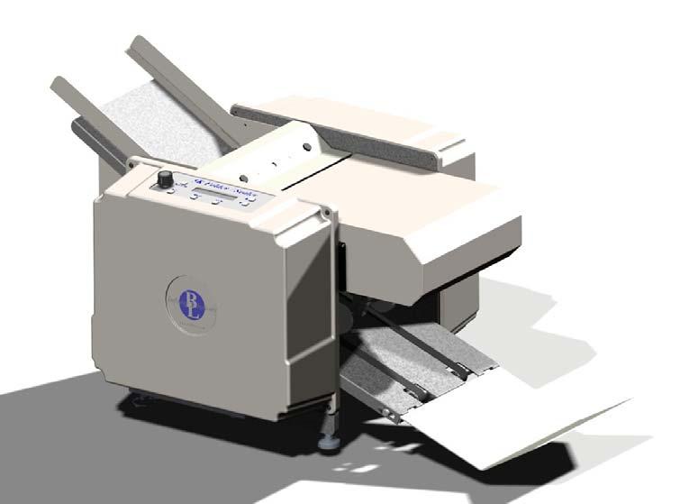
6 1. Machine Overview Read the operators manual to become familiar with the machine operation. Feed Gauge Cover Paper Guide Electrical Side Cover Feed Table Upper Fold Plate Conveyor Nip Wheels Drive Train Access Door Motor Side Cover Conveyor Figure 1: A 6


7 Control Panel IEC Assembly, Fig 2 Catch Tray Lower Fold Plate Figure 1: B Power Cord Plug Power Switch / Breaker Figure 2: Power Connection and Switch 7
 Installation 1. Installation is the reverse of removal.")
8 1.1. Covers a) Removal 1. Remove the cover screws (4x). 2. Slide the cover off the machine. b) Installation 1. Installation is the reverse of removal. Cover Figure 3: Covers Cover Screw (4x) 8
 Removal Disconnect the power cord from the machine. 1. Remove the drive train side cover. 2. Roll the o-ring off of the conveyor pulley.")

9 2. Drive Train Roll Gear Feed Drive Belt Feed Drive Pulley Door Switch Double Sided Belt Feed Pinion Pulley Conveyor Pulley Motor Belt Motor Pulley and Clutch Figure 4; Drive Train Note: If motor belt is marked 5M450 15, then see addendum 2.1. Conveyor Drive Pulley & O-Ring a) Removal Disconnect the power cord from the machine. 1. Remove the drive train side cover. 2. Roll the o-ring off of the conveyor pulley. 3. Remove the conveyor pulley. a) Loosen the set screw. b) Pull the pulley off of the shaft. O-Ring b) Installation 1. Place the conveyor pulley onto the shaft with the hub on the Figure 5: Conveyor Drive inside. 2. Align the O-Ring grove in the pulley with the O-Ring grove on the roll shaft. Note: The conveyor pulley is mounted on a floating shaft and the pulley will self align itself, however is best if they are closely aligned to begin with. Tighten the set screw 3. Roll the o-ring onto the conveyor pulley. 4. Ensure the o-ring or pulley can not contact any other drive train components. 9
 Removal Disconnect the power cord from the machine 1. Loosen all four motor screws and slide the drive motor forward to loosen the belt tension. 2.")

10 Note: For conveyor pulley and O-ring part # s see the Appendix. If existing pulley does not have shown hub, then the clear o-ring must be used. Otherwise, the black one is needed Drive Motor: Belt, Pulleys, and Clutch a) Removal Disconnect the power cord from the machine 1. Loosen all four motor screws and slide the drive motor forward to loosen the belt tension. 2. Slide motor belt off of the motor pulley. 3. Remove the motor clutch and pulley. a) Loosen set screw. b) Pull the motor clutch and pulley off of the motor shaft. Note: If the motor pulley needs to be removed from the clutch, remove the set screws, the large center nut on the clutch and disassemble. To break the nut loose reinstall the belt, place a socket driver on the end of the hex shaft and loosen the center nut on the clutch. Alternately, if the clutch is already removed, the inside can be placed in a vise and the center nut can be loosened. 4. Remove the roll drive pulley. a) Loosen both the set screws. b) Slide the pulley off of the shaft. Figure 6: Drive Motor System b) Installation 1. Install the roll drive pulley onto the roll shaft with hex end. Ensure the drive key is properly placed in the keyway. Butt the pulley up with the coinciding pulley on the shaft and tighten both set screws. 2. Install the motor clutch and pulley onto the motor shaft. Ensure the drive key is properly placed in the keyway. Note that an undersized 3/16 key is used. 3. Slide the belt onto the pulleys. Align the motor clutch and pulley on the motor shaft so that the belt rides on the middle of the pulley. Tighten the set screw. 4. Adjust the belt tension (See Section 2.2.c) 5. Check for clearance of the belt between nearby pulleys and ensure there will be no interference. If any interference is found realign pulleys. c) Adjustments Belt Tension 1. With the motor mounting screws loose, slide the drive motor back until the belt is taut. Tighten the motor mounting screws. Motor Clutch Adjustment The motor clutch must be adjusted if: (i) Being replaced (ii) The motor pulley has been removed from the clutch (iii) The center nut on the clutch has been loosened or tightened. Note: If improperly adjusted premature component failure or poor machine performance can occur. 1. Use a torque wrench to tighten the center nut of the clutch to 12 ft/lbs. Figure 7: 1 and 2/3 forms folded together 10
 through the back of the machine while it runs at full speed (See Figure 8).")
 The form should make it through with minimal slipping of the motor. Note: by listening to the motor you will be able to hear if it slips.")
11 2. With the drive train completely assembled and all protective guards in place plug in the machine and power it on. 3. Test the adjustment by running a 1 2/3 folded form (See Figure 7) through the back of the machine while it runs at full speed (See Figure 8). a) To feed the form into the back of the machine, remove the rear fold plate. The fold plate switch will have to be depressed to run the machine in the forward direction. b) The form should make it through with minimal slipping of the motor. Note: by listening to the motor you will be able to hear if it slips. If the form does not make it through the machine then the clutch is too loose: tighten the clutch and repeat. 4. To determine if the clutch is too tight run two forms folded together through the back of the machine. The paper should not make it through the machine, however the clutch should slip. You will be able to briefly hear this just as the motor shuts down. If the clutch does not slip at all loosen the center nut. 5. Repeat steps 3 and 4 until both above criteria are met. Insert folded form here for clutch adjustment Note: If pulley material is aluminum, then see addendum Figure 8: Back of the Machine Figure 9: Motor Clutch Exploded View 11
12 2.3. Double Sided Timing Belt and Drive Pulleys Figure 10: Drive Train Exploded View a) Removal Disconnect the power cord from the machine. 1. Remove the conveyor pulley, motor belt and the gears. (See Section 2.2) 2. Remove the double sided belt. a) Loosen the idler tension bracket and slide the bracket and pulley down to release tension on the belt. b) Remove the idler pulley from the bracket. Note: The pulley uses a double screw attachment and both sides must be held to unscrew the screws. 3. Remove the roll pulleys. a) Loosen the set screws and remove the pulleys. 4. Remove the belt. b) Installation 1. Installation is the reverse of removal. 2. Adjust belt tension. (See Section 2.2C) 12
13 c) Adjustments 1. With the idler bracket loose, slide the idler wheel and bracket up until the belt is tight. Tension the belt so that the belt and gears move freely with minimal resistance. If the belt is too loose excess noise and premature belt failure can occur. 3. Feed System Figure 11: Feed Assembly 3.1. Feed Table (See Figure 1A) a) Removal Disconnect the power cord from the machine. 1. Remove both the side covers. 2. Remove the feed pulleys and belt. 3. Remove the feed table screws, 2x per side (4x total). 4. Remove the feed table. b) Installation 1. Installation is the reverse of removal. 13
 3. Slide the drive shaft through the drive train side frame. 4. Pull the idler shafts out the back side of the chassis. 5. Remove the belts.")
14 3.2. Feed Drive Belts a) Removal Disconnect the power cord from the machine 1. Remove the E-clips from the drive shaft (4x). (See Figure 11) 2. Remove shaft support screws from the side frames. (See Figure 12) 3. Slide the drive shaft through the drive train side frame. 4. Pull the idler shafts out the back side of the chassis. 5. Remove the belts. a) Inspect the belts for any wear or damage. If any is found replace the belts. b) Installation 1. Place the idler rollers onto the idler shafts and place the belt around the rollers. a) Insert the drive roller inside the belts. (Note: ensure that the 1-way bearing is positioned on the side closest to the electrical side frame) b) Insert the idler shafts, rollers and belts into the chassis and insert shaft screws into the side frame. Note: The crowned roller goes to the back of the machine. (See Figure 1111) 2. Insert the drive shaft through drive train side frame, insert the shaft into the drive roller as the shaft is being inserted into the side frame. 3. Replace the E-clips (4x). 4. Ensure belts are aligned and are oriented with the blue side visible. 5. Reinstall feed pulleys and belt. Figure 12: Feed Rollers and Belts c) Adjustment Paper Feed Tray Width Adjustment Place a squared up stack of the paper to be used into the tray and align the paper to the fixed side of the tray. Adjust the sliding side so that there is approximately 1/8 inch between the stack of paper and the guide. If there is no gap the paper may bind and not feed; if too loose paper may feed crooked. 14
 4. Pull the feed gauge assembly up and out of the machine.")
15 4. Feed Gauge Assembly Figure 12: Feed Gauge Assembly d) Removal Disconnect the power cord from the machine. 1. Remove the feed gauge cover. 2. Remove both side covers. 3. Remove the x-tie screws from both side frames. (See Figure 22) 4. Pull the feed gauge assembly up and out of the machine. Note: If the x-tie is too tight in the chassis to remove it may be necessary to loosen the feed table, feed idler shafts, conveyor, sensor x-tie, and front & rear motor guard screws on the motor side frame. (See Figure 22, Page 22) Adjustment Screw Figure 13: Cross-section of Feed Gauge e) Installation 1. Assembly is the reverse of the removal. 15
16 2. Adjust the feed gauge. f) Adjustment Disconnect the power cord from the machine. 1. Remove feed gauge cover 2. Place 1 form on the feed table and hand feed the form into the machine by moving the feed belt with your hand. 3. Pull the paper out of the machine. You should feel resistance, but not too much. Turn the adjustment screw clockwise for less resistance and counter-clockwise for more resistance. 16
17 5. Nip Wheel g) Removal NOTE: Static Brush Part # not shown Figure 15: Nip Wheel Disconnect the power cord from the machine. 1. Remove upper fold plate. 2. Remove 3 Felt Holder thumb screws and remove felt holder assembly 3. While holding NIP WHEEL Assembly, remove 2 screws holding Sensor Mount Bracket and swing assembly down onto exit conveyor. 4. Unplug sensor cable from sensor and remove NIP Wheel Assembly h) Installation Installation is the reverse of the removal. i) Adjustment Note: The nip wheel should be adjusted every time a new fold or form is used that yields a different final size. 1. Set the form with desired fold onto the conveyer so that it is touching the edge of the roll. 2. Adjust the nip wheel so that it is ½ from the other side of the folded form. (See Figure 16) 17

18 Roll Nip Wheel Folded Form Figure 16: Nip Wheel Adjustment 6. Conveyor NIP WHEELS MAY NOT BE WHITE Figure 17: Extended Conveyor 18
 j) Removal Disconnect the power cord from the machine. 1. Remove the E-clips on both the idler shafts (8x). 2. Remove the springs from both idler shafts.")
19 6.1 Extended Conveyor Belts Note: Only the 7K Plus is equipped with the extended conveyor, the 5K is equipped with the standard conveyor which does not contain the additional conveyor table and belts. (This may be purchased as an option) j) Removal Disconnect the power cord from the machine. 1. Remove the E-clips on both the idler shafts (8x). 2. Remove the springs from both idler shafts. Note: Different size springs are used for the intermediate idler shaft and for the final idler shaft. 3. Remove the feet from the final idler shaft. 4. Slide and orient the final idler shaft in table slot to allow for removal and slide the shaft out of the table. 5. Remove the extended conveyor arm from one side of the extended conveyor. 6. Slide and orient intermediate idler shaft in the table slot to allow for remove and then slide it out of the table. 7. Remove the conveyor belts. k) Installation 1. Place the conveyor belts around the rolls on both conveyor tables. 2. Place the extended table near the conveyor table and insert the intermediate shaft into the table, making sure that the belts for the extended conveyor are on the pulleys. Figure 18: Conveyor 3. Reattach extended conveyor arm. 4. Orient the shaft such that the bore for the spring is aligned with the notch for the spring, insert springs. 5. Insert E-Clips onto the intermediate idler shaft (4x). 6. Place and hold the final idler rollers inside the extended conveyor belt. 7. Slide the final idler shaft in place. 8. Insert E-Clips (4x). 9. Orient the shaft such that the bore for the spring is aligned with the notch for the spring, insert springs. 10. Reattach the feet so that the conveyor table sits evenly. 19

20 7. Wiper ITEM PartNo DESCRIPTION QTY Felt Holder Wiper Felt Strip Black #10-32 Thumb Screw MATERIAL THIS DOCUMENT AND THE DATA DISCLOSED HERIN OR FINISH HEREWITH IS NOT TO BE REPRODUCED, USED OR DISC- LOSED IN WHOLE OR IN PART TO ANYONE WITHOUT THE PERMISSION OF BRI-LIN CORPORATION B L UNLESS OTHERWISE SPECIFIED ALL DIMENSIONS ARE IN INCHES TOLERANCES: ANGLES 1 1 PLACE DECIMALS.05 DRAWING TITLE 2 PLACE DECIMALS PLACE DECIMALS PLACE DECIMALS.0005 Bri-Lin Corporation 16 Amarosa Drive Rochester, NH WIPER ASSEMBLY PART # REVISION DRAWN BY MD A AAS 1:1.5 1/11/2005 DRAWING # SCALE DRAWING DATE (1) Removal Figure 19: Wiper Assembly 1. Remove all three thumb screws. 2. Slide the wiper assembly off the x-tie and remove from the machine. 3. Inspect the felt wiper, if it is dirty flip over or replace. (2) Installation 1. Slide the wiper assembly in place. 2. Insert the two thumb screws facing out the front of the machine. 3. Adjust the pressure on the roll so the felt is slightly touching. Check that the holder is parallel with the roll. Note: If the felt is pressing too hard on the roll it can increase the load on the motor and reduce the performance of the machine. If the felt is not contacting the roll it will not properly clean and can mark up the forms with ink. 4. Insert the last thumb screw into the top of the felt holder. 20
 2. Remove the fold trays, simply lift up trays and slide out of chassis. 3. Remove the feed gauge x-tie mounting screws from the drive train side of the chassis.")
21 8. Rolls Note: If roll configuration is different than shown, see addendum Figure 20: Rolls (1) Removal Disconnect the power cord from the machine. 1. Remove the drive train components. (See Section: 2, page 9) 2. Remove the fold trays, simply lift up trays and slide out of chassis. 3. Remove the feed gauge x-tie mounting screws from the drive train side of the chassis. (See Figure 22) 4. Remove the feed table mounting screws from the drive train side of the chassis. (See Figure 22) 5. Remove the feed roller mounting screws from the drive train side of the chassis. (See Figure 22) 6. Remove the conveyor table mounting screws from the drive train side of the chassis. (See Figure 22) 7. Remove the nip wheel x-tie mounting screw from the drive train side of the chassis. (See Figure 22) 8. Remove the drive motor guards and the drive motor mounting screws. The drive motor can be left in the machine. 9. Ensure the electrical side cover is in place and on a sturdy surface tip the machine so that the electrical side is face down. Ensure the drive motor is securely resting and no wires are being pinched or stretched. 10. Remove the base plate mounting screws and rear leg from the drive train side frame. SERVICING THE ROLLS Figure 21 21
 Clean rolls by wiping down with a household cleaner such as OOPS or the equivalent. (2) Installation 1.")
22 11. Slide the drive train side frame off of the rolls and remove. 12. Inspect the rolls for wear and replace any damaged or worn components. a) Clean rolls by wiping down with a household cleaner such as OOPS or the equivalent. (2) Installation 1. Installation is the reverse of removal Cover (4x) Feed Gauge X-tie Feed Idler Shafts Nip Wheel X-Tie Feed Table Conveyor Table Rear Motor Guard Front Motor Guard Drive Motor (4x) Figure 22: Side Frame Screws This view is shown with roller bearings Note: If Frames are not as shown, see addendum Roller Bearing Needle Bearing Part # Part # BEARING IDENTIFICATION 22
 Unscrew the power switch bracket from the electrical side frame. b) Unscrew and remove the rear motor guard. 3. Disconnect the electrical leads from the motor. 4.")
23 9. Electrical Figure 23: Electrical Components a) Drive Motor Part # (1) Removal Disconnect the power cord from the machine 1. Remove both the side covers. 2. Remove the rear motor guard. a) Unscrew the power switch bracket from the electrical side frame. b) Unscrew and remove the rear motor guard. 3. Disconnect the electrical leads from the motor. 4. Remove the motor clutch with pulley. (See Section 2.2) 5. Remove the motor mounting screws and slide the motor from the chassis. Motor Part # (2) Installation 3. Installation is the reverse of the removal. 23
 Installation 1.")
 Processor Board Part #41-0468-00 (1) Removal Disconnect the power cord from the machine. 1. Remove the electrical side cover. 2.")
24 b) Control Panel See Figure 22 (1) Removal Disconnect the power cord from the machine. 1. Remove the electrical side cover. 2. Disconnect wiring of speed pot from drive board. 3. Remove 2 screws that attach Control Panel. 4. Lift the Control Panel straight up, separating it from the Processor Board 5. If faulty replace with a new unit. (2) Installation 1. Carefully install Control Panel into Processor Board through header interface 2. Reassemble in reverse order of above c) Processor Board Part # (1) Removal Disconnect the power cord from the machine. 1. Remove the electrical side cover. 2. Remove Control Panel as described above 3. Disconnect electrical connectors from the unit. 4. Remove 4 mounting screws and remove unit (2) Installation 1. Reassemble in reverse order as above (see schematic for wiring) d) NRDG Drive Part # (1) Removal Disconnect the power cord from the machine. 1. Remove the electrical side cover. 2. Disconnect electrical connectors from the drive. 3. Remove mounting screws. 4. Remove the power supply and if faulty replace with new unit. (2) Installation Reassemble in reverse order as above (see schematic for wiring) 24
25 e) 10A IEC Bracket Assembly (1) Removal Disconnect the power cord from the machine. 1. Remove the electrical side cover. 2. Disconnect electrical connections from assembly 3. Remove mounting screws and remove unit. 4. Replace failed components as required (2) Installation Reassemble in reverse order as above (see schematic for wiring) 25
26 f) IEC Outlet Assembly (1) Replacement Disconnect the power cord from the machine. 1. Remove the electrical side cover. 2. Disconnect electrical connections from assembly 3. Remove mounting screws and remove unit 4. Replace failed components as required (2) Installation Reassemble in reverse order as above (see schematic for wiring) 26

27 g) FOLD PLATE SWITCH, DPDT Part # Fold Plate Switch (1) Replacement Disconnect the power cord from the machine. 1. Remove rear fold plate. 2. Remove side covers to access rear motor cover screws 3. Remove rear motor cover screws and rear motor cover 4. Disconnect electrical connections from fold plate switch 5. Remove mounting screws and remove unit 6. Replace failed components as required (2) Installation Reassemble in reverse order as above (see schematic for wiring) 27
28 h) Door Switch Assembly (1) Replacement Disconnect the power cord from the machine. 1. Remove side door 2. Disconnect electrical connections from door switch 3. Remove mounting screws and remove unit 4. Replace failed component as required (2) Installation Reassemble in reverse order as above (see schematic for wiring) 28
29 i) NIP Wheel Assembly with Sensor (1) Replacement Disconnect the power cord from the machine. 1. Remove upper fold plate. 4. Remove 3 Felt Holder thumb screws and remove felt holder assembly 5. While holding NIP WHEEL Assembly, remove 2 screws holding Sensor Mount Bracket and swing assembly down onto exit conveyor. 6. Unplug sensor cable from sensor and remove NIP Wheel Assembly 7. Remove sensor hold down screw and remove sensor from assembly 8. Replace failed components as required (2) Installation Reassemble in reverse order as above (see schematic for wiring) 29
30 30 j. Schematic
31 10. Troubleshooting 11.1Machine Will Not Power On 1. Check that the power switch / breaker is in the on position. (when in the on position it will be lit up red) 2. Check that the power cord is properly connected to the machine. 3. Confirm the following components are not faulty in the proceeding order: a) Wall socket b) Power cord: test by switching it with a known working power cord. The machine utilized a standard IEC computer power cord. c) Power switch / breaker: If the power switch will not light up, wait a few minutes and try again. If it will still not work, replace the switch. If the power switch / breaker comes on but only stays on for short periods of time, replace the switch. d) Electrical connections: (a) Disconnect the power cord from the machine. (b) Remove electrical side cover. (c) Refer to the wiring schematic and check all electrical connections. e) If the above steps have been followed and the machine will still not power on please contact Infinity Solutions Manufacturing Machine Powers On But Will Not Run 1. Ensure the drive train cover is in place and the safety switch is engaged. Disconnect the power cord from the machine 2. Open the access panel on the drive train cover. With a 7/16 socket turn over the hex end shaft and attempt to rotate, if there is heavy resistance or it is locked proceed with the following steps. If it will rotate with minimal resistance go to step 3. a) Check for a paper jam. b) Inspect for any foreign objects in the rolls. c) Remove the drive train cover and inspect drive train components for faulty components. i) If all components appear to be in acceptable condition remove the drive motor belt and attempt to rotate the hex shaft again. If this solves the problem test the drive motor. ii) If the problem persists with the drive motor belt removed, repeat steps (a), (b), and (c) to ensure they are not the issue. If no solution is found continue removing components until the problem is isolated. 3. Minimal resistance when rotation the shaft. a) Ensure the drive train cover is in place and the safety switch is engaged. i) If a bad switch is suspected, test for continuity with a multi-meter and replace if needed b) Check proper operation of the electrical components in the following order. 1. Fold Plate Switch 2. Control Panel 3. Electrical Connections 4. Power Supply Board 5. Drive Board 6. Drive Motor 11.3 Machine Stops Running 1. If the machine is still powered on, check to see if the forms on the exit conveyor of the machine are blocking the counter sensor. (If the sensor is blocked for more than1/2 second, the machine will stop to prevent a possible jam in the exit area of the machine.) 31
32 2. If the sensor is blocked, increase the starting speed of the machine before pressing RUN. (This may be necessary on machines that are running 14 EZ or Return Envelopes.) Also check that NIP Wheel assembly is properly adjusted. 3. If the machine powered off while running check the power switch / breaker. a) If the machine repeatedly shuts off, wait a few minutes and test again. If the problem persists test the power switch / breaker Paper Jams Automatically Clearing a Jam 1. Remove all paper from the feed table. 2. If the breaker power switch has tripped (light is off) then flip it to the on (lighted) position. 3. Remove both fold plates. 4. Press the reverse button to remove paper from the back of the machine. 5. If the paper is not moving or you cannot see it, then you need to manually clear the jam. (See Section Replace the fold plates Manually Clearing a Paper Jam Disconnect the power cord from the machine. 1. Remove all paper from the feed table. 2. Remove both fold plates from the machine. 3. Remove the access panel in the motor side cover. 4. Place the breaker bar socket over the shaft with the hex end. 5. Rotate the breaker bar in either direction until the jammed form is out of the machine. 6. Replace the fold plates. 7. Replace the paper on the feed table. 8. Replace the side cover access panel. 9. Make sure that the power switch is in the off position. 10. Connect the power cord to the machine Diagnosing the Paper Jam Table 1 outlines the different problems which cause paper jams and the symptoms which will help you to identify the cause. Problem Double Feed Buckled Form Bad Fold Symptom Unfold the form that caused the jam, you will find that it is actually two forms folded together. There will be an extra fold in form near the correct fold location. The form which caused the jam will be folded crooked. Causes Bad Feed Gauge Setting Too much paper on the feed table Wrong fold plate setting Feed Table Paper Guide set improperly Fold Plates set improperly Solution ¼ Turn CCW on feed gauge adjust screw Check both fold plates. Make sure they are set to the correct mark on the scale. Check both fold plates. Make sure that both paper stops are square. 32 Table 1: Paper Jam Diagnostics
33 11.5 Improper Functioning of the Machine Misaligned Folds If your forms are running through the machine OK but they re folding a little bit crooked or are not folding right on the perforation, you need to adjust the fold plate settings. The location of perforations on forms generally fluctuates by about 1/16 in either direction. Forms manufacturers do this to avoid the forms sticking together. Because of this fluctuation, it is sometimes necessary to fine tune the placement of the paper stop on the fold plates. The first step is to identify which fold plate is misaligned. Watch the form as it is fed into the machine, and then compare it to the finished form. Once you ve identified which fold plate needs to be adjusted, remove it from the machine. If the fold is crooked, check to make sure that the paper stop is parallel to the front edge of the fold plate. Check that the indicator points on the paper stop indicate the same reading on the two scales of the fold plate. Also check the feed table to make sure that paper guides are set correctly. If the fold is just a bit off of the perforation, adjust the paper stop by the amount that the fold is off. If the fold is happening early, then move the paper stop away from the open end of the fold plate. If the fold is happening late, then move the paper stop towards the open end of the fold plate Paper Feed Problems Double Feeds If the machine is occasionally feeding two forms at once, readjust the feed gauge Won t Feed If your machine won t feed forms through: 1. Try reducing the size of the paper stack on the feed table. a) Adjust the feed table paper guides. 2. Try resetting the feed gauge Dirty forms 1. Clean rolls with OOPS or an equivalent cleaning solvent. a) Spray solvent onto a clean rag and wipe down rolls. 2. Inspect felt wiper. a) Replace if dirty or flip over Motor Runs only in one direction 1. Check the rear fold plate and ensure it is properly installed. 2. Test the fold plate switch. (See Section ) Excessive Noise Note: These machines are capable of processing up to 7,000 forms per hour. Some noise is to be expected. Be alert for unusual noises or grinding sounds. Disconnect the power cord from the machine. 1. Check for paper jam or foreign object in rolls. a) If a paper jam is found see section Remove drive train side cover. a) Inspect entire drive train for damaged, worn, improperly tensioned or misaligned components. Particularly take note of the condition of the belts. 33
 If the noise if no longer present the problem has been isolated to the drive train system.")


34 b) If no visual problems, remove the motor drive belt. (a) Replace drive train cover and power machine on and run the motor. If the noise is still present replace the motor. (b) If the noise if no longer present the problem has been isolated to the drive train system. Check drive train components again, check rolls, conveyor system for damaged components or foreign object Poor Stacking 1. Adjust the nip wheel. Note: The nip wheel should be adjusted every time a new fold or form is used that yields a different final size. 2. Check the conveyor belts for any damage. 3. With the machine running observe the conveyor belts and ensure they are operating properly Sensors 1. Reflective Counter Sensor, if counter is not functioning correctly check exit NIP Wheel assembly I set correctly. 2. Check wiring that connections are being made Door Switch Test the continuity, if the continuity does not correspond to the table below replace the switch. Figure 4: Sensor SENSOR Table 2: Door Switch Continuity 1 & A 1 & B 1 Switch Closed Open Continuity Switch Open Continuity No Note: Normal operation requires that wires be connected to Terminals 1 and B A B Figure 5: Door Switch 34

35 Fold Plate Switch Test the continuity, if the continuity is not correct, replace the switch. This is a double pole double throw switch with N/C, N/O, and Common identified on the switch. N/C SWITCH 1 N/O SWITCH 2 COMMON SW1 N/C SWITCH 2 COMMON SW2 N/O SWITCH 2 Figure 8: Fold Plate Switch
36 11. Appendix 36 Side Frame Assembly Drawings


37 SHEET 2 OF 2 ITEM PartNo DESCRIPTION QTY Lower Fold Plate Lower Fold Plate Bottom Fold Plate Paper Stop Fold Plate Paper Stop Base Hardened Flat Washer Red #10-32 Thumb Screw Scale UNLESS OTHERWISE SPECIFIED ALL DIMENSIONS ARE IN INCHES TOLERANCES: ANGLES 1 1 PLACE DECIMALS.05 2 PLACE DECIMALS PLACE DECIMALS PLACE DECIMALS.0005 MATERIAL THIS DOCUMENT AND THE DATA DISCLOSED HERIN OR HEREWITH IS NOT TO BE REPRODUCED, USED OR DISC- FINISH LOSED IN WHOLE OR IN PART TO ANYONE WITHOUT THE PERMISSION OF BRI-LIN CORPORATION B L DRAWING TITLE Bri-Lin Corporation 16 Amarosa Drive Rochester, NH LOWER FOLD PLATE ASSEMBLY, 3K PART # REVISION DRAWN BY B AAS DRAWING # SCALE DRAWING DATE MD :3 7/21/2005 SHEET 2 OF ITEM PartNo DESCRIPTION QTY Fold Plate Paper Stop Fold Plate Paper Stop Base Lower Fold Plate Lower Fold Plate Bottom Hardened Flat Washer Red #10-32 Thumb Screw Upper Foldplate Scale UNLESS OTHERWISE SPECIFIED ALL DIMENSIONS ARE IN INCHES TOLERANCES: ANGLES 1 1 PLACE DECIMALS.05 2 PLACE DECIMALS PLACE DECIMALS PLACE DECIMALS.0005 MATERIAL THIS DOCUMENT AND THE DATA DISCLOSED HERIN OR HEREWITH IS NOT TO BE REPRODUCED, USED OR DISC- FINISH LOSED IN WHOLE OR IN PART TO ANYONE WITHOUT THE PERMISSION OF BRI-LIN CORPORATION B L DRAWING TITLE Bri-Lin Corporation 16 Amarosa Drive Rochester, NH UPPER FOLD PLATE ASSEMBLY, 3K REVISION DRAWN BY PART # A AAS DRAWING # SCALE DRAWING DATE :3 7/21/
38 38 7KPlus Exploded Drive Train

39 Retard Assembly Optional Indexing Feed Retard Assembly 39

40 12. Addendums Over the last several years, the 7KPlus has changed several times. Listed in this addendum are most of the changes that have been made. If the machine being serviced does not have the components listed, contact Infinity Solutions Manufacturing. 7KPlus with Gear Driven Feed 40 Drive Train w/15mm Belt

41 Roll Gears Feed Drive Gear Double Sided Belt Conveyor Pulley Feed Pinion Gear Idler Gear Door Switch Motor Belt Motor Pulley and Clutch 41

42 SHEET 2 OF 3 13 ITEM PartNo DESCRIPTION QTY Spur Gear, Pinion Spur Gear, Feed Spur Gear, Large Idler Spur Gear, Roll Drive Feed Idler Bracket SHCS x SHLDR 1/2 x 3/4 x 3/ Set Screw, SSS #10-32 x 1/4" Set Screw, SSS 4-40 x MATERIAL THIS DOCUMENT AND THE DATA DISCLOSED HERIN OR FINISH HEREWITH IS NOT TO BE REPRODUCED, USED OR DISC- LOSED IN WHOLE OR IN PART TO ANYONE WITHOUT THE PERMISSION OF BRI-LIN CORPORATION Feed Gear Cluster 1. Removal B L UNLESS OTHERWISE SPECIFIED ALL DIMENSIONS ARE IN INCHES TOLERANCES: ANGLES 1 1 PLACE DECIMALS.05 DRAWING TITLE 2 PLACE DECIMALS PLACE DECIMALS PLACE DECIMALS.0005 Bri-Lin Corporation 16 Amarosa Drive Rochester, NH CHASSIS PART # REVISION DRAWN BY DRAWING # SCALE DRAWING DATE MD :2 7/27/2005 Disconnect the power cord from the machine. 1. Remove the large idler gear by removing the shoulder-bolt on which it is mounted. 2. To remove the pinion idler, feed gear and drive gears. a) Loosen set screw(s). b) Pull the gear off of the shaft. 3. Inspect gears for broken or chipped teeth. Replace the gear if any defects are found. 2. Installation 1. Place the upper and lower roll drive gears onto the roll shafts. Note: Only the lower roll drive gear requires a shaft key and it should already be present because it is shared with the roll drive pulley. The upper roll drive gear does not require a keyway. However the set screw should be positioned to tighten into the key slot on the shaft. 2. Visually align the gears and tighten set screws. 3. Install the feed gears. a) Place the large idler gear on the shoulder-bolt and tighten the bolt into the idler block. b) Slide the feed gear on the feed drive shaft and the small idler gear on to the feed roll shaft. (See Error! Reference source not found.) c) Tighten set screws 42
43 Double Sided Timing Belt and Drive Pulleys a) Removal Disconnect the power cord from the machine. 1. Remove the conveyor pulley, motor belt and the gears. (See Section 2.2) 2. Remove the double sided belt. a) Loosen the idler tension bracket and slide the bracket and pulley down to release tension on the belt. b) Remove the idler pulley from the bracket. Note: The pulley uses a double screw attachment and both sides must be held to unscrew the screws. 3. Remove the roll pulleys. a) Loosen the set screws and remove the pulleys. 4. Remove the belt. b) Installation 1. Installation is the reverse of removal. 2. Adjust belt tension. (See Section 2) 43


44 3. Adjustments 1. With the idler bracket loose, slide the idler wheel and bracket up until the belt is tight. Tension the belt so that the belt and gears move freely with minimal resistance. If the belt is too loose excess noise and premature belt failure can occur Feed Gauge 6 7 ITEM PartNo DESCRIPTION QTY Sprung Feed Guage X-Tie Sprung Feed Guage Roll Feed Guage Slide Pin Feed Guage Clear O-Ring Feed Retard Spring Black #10-32 Thumb Screw Adjustment Screw Feed Guage Cover FHSCS #10-32 x 1" UNLESS OTHERWISE SPECIFIED ALL DIMENSIONS ARE IN INCHES TOLERANCES: ANGLES 1 1 PLACE DECIMALS.05 2 PLACE DECIMALS PLACE DECIMALS PLACE DECIMALS.0005 MATERIAL THIS DOCUMENT AND THE DATA DISCLOSED HERIN OR FINISH HEREWITH IS NOT TO BE REPRODUCED, USED OR DISC- LOSED IN WHOLE OR IN PART TO ANYONE WITHOUT THE PERMISSION OF BRI-LIN CORPORATION B L Bri-Lin Corporation 16 Amarosa Drive Rochester, NH DRAWING TITLE FEED GUAGE ASSY LARGE MACHINE REVISION DRAWN BY PART # A AAS DRAWING # SCALE DRAWING DATE MD :2 1/18/2005 a) Removal Disconnect the power cord from the machine. 1. Remove the feed gauge cover. 2. Remove both side covers. 3. Remove the x-tie screws from both side frames. 4. Pull the feed gauge assembly up and out of the machine. Note: If the x-tie is too tight in the chassis to remove it maybe necessary to loosen the feed table, feed idler shafts, conveyor, sensor x-tie, and front & rear motor guard screws on the motor side frame. 4. Installation 1. Assembly is the reverse of the removal. 2. Adjust the feed gauge. Adjustment Screw Paper Form Cross-section of Feed Gauge 44
45 5. Adjustment Disconnect the power cord from the machine. 1. Remove feed gauge cover 2. Place 1 form on the feed table and hand feed the form into the machine by moving the feed belt with your hand. 3. Pull the paper out of the machine. You should feel resistance, but not too much. Turn the adjustment screw clockwise for less resistance and counter-clockwise for more resistance. Nip Wheels 9 ITEM PartNo DESCRIPTION QTY Nip Wheel Caster Nip Wheel Block Nip Wheel Nip Wheel T-Hinge Shoulder Screw, 1/4" x 5/8" x # Set Screw, SSS #10-32 x 1/4" Red #10-32 Thumb Screw E-Clip, 1/4" Shaft,.025" Thick Mylar Velvet MATERIAL THIS DOCUMENT AND THE DATA DISCLOSED HERIN OR HEREWITH IS NOT TO BE REPRODUCED, USED OR DISC- FINISH LOSED IN WHOLE OR IN PART TO ANYONE WITHOUT THE PERMISSION OF BRI-LIN CORPORATION Nip Wheel UNLESS OTHERWISE SPECIFIED ALL DIMENSIONS ARE IN INCHES TOLERANCES: ANGLES 1 1 PLACE DECIMALS.05 2 PLACE DECIMALS PLACE DECIMALS PLACE DECIMALS.0005 B L DRAWING TITLE Bri-Lin Corporation 16 Amarosa Drive Rochester, NH PART # REVISION DRAWN BY MD DRAWING # SCALE DRAWING DATE A 1:3 1/11/2005 a) Removal Disconnect the power cord from the machine. 1. Remove both the side covers. 2. Remove the x-tie screws from both side frames. 3. Slide the nip wheel assembly out of the front of the machine. 6. Installation Installation is the reverse of the removal. NIP WHEELS MAY NOT BE WHITE Roll 7. Adjustment Note: The nip wheel should be adjusted every time a new fold or form is used that yields a different final size. 1. Set the form with desired fold onto the conveyer so that it is touching the edge of the roll. Nip Wheel Folded Form 2. Adjust the nip wheel so that it is ½ from the other side of the folded form. Nip Wheel Adjustment 45

46 Sealer Rollers SHEET 3 OF 3 38 ITEM PartNo DESCRIPTION Rolls Config/ QTY Hardened Race Urethane Feed Roll Feed Drive Roll Hex End Roll Conveyor Drive Roll " Delrin Thrush Washer " Delrin Thrush Washer MATERIAL THIS DOCUMENT AND THE DATA DISCLOSED HERIN OR FINISH HEREWITH IS NOT TO BE REPRODUCED, USED OR DISC- LOSED IN WHOLE OR IN PART TO ANYONE WITHOUT THE PERMISSION OF BRI-LIN CORPORATION Rolls B L UNLESS OTHERWISE SPECIFIED ALL DIMENSIONS ARE IN INCHES TOLERANCES: ANGLES 1 1 PLACE DECIMALS.05 DRAWING TITLE 2 PLACE DECIMALS PLACE DECIMALS PLACE DECIMALS.0005 Bri-Lin Corporation 16 Amarosa Drive Rochester, NH CHASSIS PART # REVISION DRAWN BY DRAWING # SCALE DRAWING DATE MD :3 7/25/ a) Removal Disconnect the power cord from the machine. 1. Remove the all drive train components. (See Section: 0) 2. Remove the fold trays, simply lift up trays and slide out of chassis. 3. Remove the feed gauge x-tie mounting screws from the drive train side of the chassis. (See Figure ) 4. Remove the feed table mounting screws from the drive train side of the chassis. (See Figure ) 5. Remove the feed roller mounting screws from the drive train side of the chassis. (See Figure ) 6. Remove the conveyor table mounting screws from the drive train side of the chassis. (See Figure ) 7. Remove the nip wheel x-tie mounting screw from the drive train side of the chassis. (See Figure ) Figure 6: Rolls 8. Remove the counter sensor x-tie mounting screw from the drive train side of the chassis. (See Figure ) 9. Remove the drive motor guards and the drive motor mounting screws. The drive motor can be left in the machine. 10. Ensure the electrical side cover is in place and on a sturdy surface tip the machine so that the electrical side is face down. Ensure the drive motor is securely resting and no wires are being pinched or stretched. 11. Remove the base plate mounting screws and rear leg from the drive train side frame. 12. Slide the drive train side frame off of the rolls and remove.

47 13. Inspect the rolls and delrin spacers for wear and replace any damaged or worn components. a) Clean rolls by wiping down with a household cleaner such as OOPS or the equivalent. 8. Installation 1. Installation is the reverse of removal Note: Make sure the correct spacers are installed on each shaft. Cover (4x) Feed Gauge X-tie Feed Idler Shafts Feed Table Counter X-Tie Nip Wheel X-Tie Conveyor Table Rear Motor Guard Front Motor Guard Drive Motor (4x) Side Frame Screws This view is shown with needle bearings with hardened race ROLLER BEARING NEEDLE BEARING Part # Part # BEARING IDENTIFICATION 47
")
")


48 Phone (866) Fax (603)
IMPORTANT! DO NOT THROW AWAY THE SHIPPING CARTON AND PACKING MATERIAL
 Operator s Manual IMPORTANT! DO NOT THROW AWAY THE SHIPPING CARTON AND PACKING MATERIAL ii Table of Contents Operator Safety... 1 Introduction... 2 Unpacking and Setup... 3 Unpacking... 3 Setup... 4 ROCKET
CALIFORNIA TRIMMER MOWER MAINTENANCE MANUAL
 CALIFORNIA TRIMMER MOWER MAINTENANCE MANUAL 2 Table of Contents Section 1: General Information Page Handle Assembly Instructions 4 Maintenance All Models 6 Oil Change Procedures All Models 9 Height Adjustment
Sure-Feed Engineering Inc. SE-900-EI. Operation & Parts Manual
 . SE-900-EI Operation & Parts Manual SE 900 EI OWNERS MANUAL Table of Contents 1. Installation guide 2. Set-up instructions 3. Operation instructions 4. Cleaning 5. Troubleshooting 6. Parts manual 7. Electrical
Maintenance and Repair
 Maintenance and Repair WARNING ALWAYS shut off the engine, remove key from ignition, make sure the engine is cool, and disconnect the spark plug and positive battery terminal from the battery before cleaning,
XPS-ProFeed Shuttle SERVICE MANUAL. Revised:
 XPS-ProFeed Shuttle SERVICE MANUAL Revised: 9-14-15 RENA SYSTEMS INC. 910 East Main Street; Suite 200 Norristown, PA 19401-4110 Phone: (610) 650-9170 Fax: (610) 270-3947 Web Site: www.renausa.com SAFETY
XPS-ProFeed Shuttle SERVICE MANUAL. Revised:
 XPS-ProFeed Shuttle SERVICE MANUAL Revised: 1-14-15 RENA SYSTEMS INC. 910 East Main Street; Suite 200 Norristown, PA 19401-4110 Phone: (610) 650-9170 Fax: (610) 270-3947 Web Site: www.renausa.com SAFETY
SE-1200-MP ECO - SERIES
 Inc. SE-1200-MP ECO - SERIES Operation & Parts Manual SE 1200 MP ECO -SERIES OWNERS MANUAL Table of Contents 1. Installation guide 2. Set-up instructions 3. Operation instructions 4. Cleaning 5. Troubleshooting
2020 Dual Tabber Operation Manual
 2020 Dual Tabber Operation Manual Revision 1.2 10 Clipper Road 10/24/2006 West Conshohocken, PA 19428-2721 Tel : 800-523-0320 / 610-825-6205 Fax: 610-825-1397 www.secap.com Index SECTION 1 Introduction
Marsh Shipping Supply Co. LLC. Marsh TD2100 Electric Taper Technical Manual
 Marsh Shipping Supply Co. LLC Marsh TD2100 Electric Taper Technical Manual 2 A wall-socket must be close to the product and readily accessible. The overall system is protected against overload by the branch
Perfmaster Air V3. Serial Number. Date
 Perfmaster Air V3 12-2015 Serial Number Date TABLE OF CONTENTS SPECIFICATIONS.3 SAFETY PROCEDURES/CARE & MAINTENANCE..4 COMPONENT IDENTIFICATION 5 DELIVERY TRAY ASSEMBLY.6 PAPER STOP ASSEMBLIES..7 MACHINE
SE-600-P Eco-Series. Operation & Parts Manual
 SE-600-P Eco-Series Operation & Parts Manual SE 600 PC & PS SERIES OWNERS MANUAL Table of Contents 1. Set-up instructions 2. Bridge-Tramming Procedure 3. Operation instructions 4. Cleaning 5. Troubleshooting
Maintenance Information
 45530136 Edition 1 July 2008 Electric Screwdrivers EL 24V DC Series Maintenance Information Save These Instructions WARNING Always wear eye protection when operating or performing maintenance on this tool.
Sofa Slideout Assembly OWNER'S MANUAL. Rev: Page 1 Sofa Slideout Owners Manual
 Sofa Slideout Assembly OWNER'S MANUAL Rev: 06.14.2016 Page 1 Sofa Slideout Owners Manual TABLE OF CONTENTS Warning, Safety, and System Requirement Information 3 Product Information 3 Prior to Operation
Maintenance Information
 Form 16575334 Edition 1 April 2005 Electric Screwdrivers EL, EP and ET 34V DC Series Maintenance Information Save These Instructions WARNING Maintenance procedures have the potential for severe shock hazard
1 Green Pressure Regulator Spring Automatic transmissions operate at temperatures between 150ºF and
 Installation Instructions for 603107 Valve Body Kit C-4 1970 & Later Tools Required Speed Handle or Ratchet 3/8 Drive 1/2 Socket 3/8 Drive 7/16 Socket 3/8 Drive 5/16 Socket 3/8 Drive Small Screwdriver
Embedded Rack Slide-out System
 Embedded Rack Slide-out System SERVICE MANUAL Rev: 02.16.2017 Page 1 Electric Embedded Rack Slide-out System TABLE OF CONTENTS Safety Information 3 Product Information 3 Operation 4 Extending Slide-Out
Service Manual Gulf Stream Electronic Full Wall Slide Systems
 Service Manual Gulf Stream Electronic Full Wall Slide Systems CONTENTS Page Before you operate the slide system 2 Operating Instructions 3 Preventive maintenance 3 Manually overriding your slide system
BOLT-ON AND WELD-ON FLUSH FLOOR SLIDEOUT SYSTEMS OPERATION AND SERVICE MANUAL
 BOLT-ON AND WELD-ON FLUSH FLOOR SLIDEOUT SYSTEMS OPERATION AND SERVICE MANUAL TABLE OF CONTENTS SYSTEM...... Warning........ Description...... Prior to Operation OPERATION... Main Components... Mechanical...
AUTOMATIC FOODSERVICE EQUIPMENT. AUTOMATIC ELECTRIC BROILER MODELS 824E & 850E and 624E & 650E. B-Series Broiler OWNER S MANUAL
 AUTOMATIC FOODSERVICE EQUIPMENT AUTOMATIC ELECTRIC BROILER MODELS 824E & 850E and 624E & 650E B-Series Broiler OWNER S MANUAL FOR YOUR SAFETY: Do not store or use gasoline or other flammable vapors or
PRODUCT INFORMATION BULLETIN #3365 DIGITAL MOTOR CONTROL PLATTER SYSTEMS For Serial Number and After
 PRODUCT INFORMATION BULLETIN #3365 DIGITAL MOTOR CONTROL PLATTER SYSTEMS For Serial Number 28640996 and After Record Platter System Identification Numbers Here: Model # Serial # Table of Contents Program
TC1000 Service Manual SALES: CUSTOMER SERVICE:
 TC1000 Service Manual SALES: 800-278-3933 CUSTOMER SERVICE: 800-745-1373 Table of Contents Section Page I. Overview 2 II. Troubleshooting Tables 3 III. Maintenance Procedures Procedure 1 Removal and Reinstallation
AUTOMATIC FOODSERVICE EQUIPMENT. AUTOMATIC ELECTRIC BROILER MODELS 952E, 932E and 922E OWNER S MANUAL
 AUTOMATIC FOODSERVICE EQUIPMENT AUTOMATIC ELECTRIC BROILER MODELS 952E, 932E and 922E OWNER S MANUAL IMPORTANT: RETAIN THIS MANUAL IN A SAFE PLACE FOR FUTURE REFERENCE. FOR YOUR SAFETY: Do not store or
TABLE OF CONTENTS. Ram Assembly
 TABLE OF CONTENTS DUC Cover------------------------------------------------------------------------------------ 00 Table of Contents----------------------------------------------------------------------------
OPERATION AND PARTS MANUAL
 OPERATION AND PARTS MANUAL MODEL NUMBER : PART NUMBER : GTL 1110 1900-0510 SERIAL NUMBER : BAYNE MACHINE WORKS, INC. PHONE: (864) 288-3877 910 FORK SHOALS ROAD TOLL FREE: (800) 535-2671 GREENVILLE S.C.,
Return to Instruction Sheet index. Installation Instructions For C-4 70 and Later, Except 70 Falcon
 Page 1 of 8 Return to Instruction Sheet index TCI 260100 Trans-Scat Automatic Transmission Installation Instructions For C-4 70 and Later, Except 70 Falcon TCI 260100 Kit Contains: Qty. Description One
Auto Sentry-eXP Maintenance. Revised 12/21/07
 Auto Sentry-eXP Maintenance Revised 12/21/07 Maintenance Procedures for Auto Sentry exp Bill Dispenser Credit Card Reader Bill Acceptor Bill Dispenser Maintenance Bill Dispenser Problem / Cause Bill Dispenser
Maintenance Information
 80234313 Edition 1 June 2006 Air Grinder, Die Grinder, Sander and Belt Sander Series G1 (Angle) Maintenance Information Save These Instructions WARNING Always wear eye protection when operating or performing
icreaseexcel Digital Creaser Operators Manual
 2-2013 6-2013 Version 1.0 3.0 icreaseexcel Digital Creaser Operators Manual WWW.MBMCORP.COM 800-223-2508 TABLE OF CONTENTS SPECIFICATIONS.1a SAFETY PROCEDURES/CARE & MAINTENANCE..1b COMPONENT IDENTIFICATION
Customer Name: Serial Number: Y-Axis Stall
 Technician Name: Date: Technician Name: Date: Customer Name: Serial Number: Y-Axis Stall Issue Explanation and Background Each drive motor on the machine (the x, y and z axes motors) has a sensor called
LS8.0T Service Manual
 LS8.0T Service Manual 1 TABLE OF CONTENTS CHAPTER 1: SERIAL NUMBER LOCATION...3 CHAPTER 2: PREVENTATIVE MAINTENANCE 2.1 Preventative Maintenance. 4 2.2 Tension and Centering the Running Belt....6 CHAPTER
DrVanos.com Stage II Installation Instructions. Tool rental is available with the purchase of a vanos kit *See website for more info*
 DrVanos.com Stage II Installation Instructions Special Tools Needed: Camshaft locking tool TDC Crank pin Sprocket turning tool Tool rental is available with the purchase of a vanos kit *See website for
Heavy Duty Miniature Quick-Change Applicator (Side-Feed Type) with Mechanical or Air Feed Systems
 with Mechanical or Air Feed Systems") Heavy Duty Miniature Quick-Change Applicator (Side-Feed Type) with Mechanical or Air Feed Systems Instruction Sheet 408-8040 30 NOV 17 Rev H Ram Assembly Ram Post Locking Screw Stock Drag Drag Release
Heavy Duty Miniature Quick-Change Applicator (Side-Feed Type) with Mechanical or Air Feed Systems Instruction Sheet 408-8040 30 NOV 17 Rev H Ram Assembly Ram Post Locking Screw Stock Drag Drag Release
WS2H/ WS3 Error Codes
 WS2H & WS3 Troubleshooting Page 1 WS2H/ WS3 Error Codes Possible Errors Code Description 1001 No Encoder Pulses 1002 Unexpected Stall, Main Drive 1003 Run Time To Long, Main Drive 14001 Message Queue Full
Overload Warning System DS 50
 Overload Warning System DS 50 Grove - FMTV Trouble Shooting Manual Level 1 - Basics - 1 Table of contents Troubleshooting Manual PAT Overload Warning system DS 50 Level 1 -Basics- Item Content Page 1.
A B C D E F. Tools Required (supplied by others)
") Page 1 of 17 Parts List Below Deck Automatic Retractable Security Cover Kit (1) Tube End Bearing Plate (A) (1) Rope Reel and Cover Drum Motor Assembly (B) (1) Cover Drum (1) Pulley Support Channel (2)
Page 1 of 17 Parts List Below Deck Automatic Retractable Security Cover Kit (1) Tube End Bearing Plate (A) (1) Rope Reel and Cover Drum Motor Assembly (B) (1) Cover Drum (1) Pulley Support Channel (2)
Thank you for purchasing a Nelson RainTrain2.
 Thank you for purchasing a Nelson RainTrain2. Read this manual carefully to learn how to operate and service your machine properly. Failure to do so can result in personal injury and/or property damage.
M52tu-M54 VANOS Assembly & Timing Using G.A.S. Professional Cam Tool Kit
 Home BMW Solutions Porsche Solutions DIY Tech Engine Services Dyno Services Machining About Contact Store Tool Rental M52tu-M54 VANOS Assembly & Timing Using G.A.S. Professional Cam Tool Kit This procedure
Tech Note Truck 14 & 15.5 Twin Plate Cast Iron Type Installation Guidelines
 1. (14 & 15.5 ) Check condition of the flywheel. Grind to resurface or replace flywheel. Surface MUST BE machined or premature clutch failure can occur. Flywheel depth must be 2.938 (74.62mm) for 14 (350mm)
SX1000 Service Manual SALES: CUSTOMER SERVICE:
 SX1000 Service Manual SALES: 800-278-3933 CUSTOMER SERVICE: 800-745-1373 Revision: August 1999 Table of Contents Section Page I. Overview 2 II. Troubleshooting Tables 3 III. Maintenance Procedures Procedure
Cybex Arc Trainer Owner s & Service Manual. 7 - Service
 7 - Service Table of Contents......... iii Warnings/Cautions All warnings and cautions listed in this chapter are as follows:! WARNING: All maintenance activities shall be performed by qualified personnel.
Model 2300DL Installation Guide
 Model 2300DL Installation Guide POWER ACCESS CORPORATION 4 HERSHEY DRIVE, DOCK 4 ANSONIA, CT 06401 800-344-0088 WEBSITE: www.power-access.com EMAIL: salesinfo@power-access.com 1 STANDARD PARTS MODEL 2300DL
OPERATION AND PARTS MANUAL
 OPERATION AND PARTS MANUAL MODEL NUMBER : PART NUMBER : GRL 1110 1900-0540 SERIAL NUMBER : BAYNE MACHINE WORKS, INC. PHONE: 864.288.3877 910 FORK SHOALS ROAD TOLL FREE: 800.535.2671 GREENVILLE SC, 29605
PORSCHE V r Valve Timing Instructions. Copyright 2009 Written by Mike Frye Edited my Adam G.
 PORSCHE 928 32V r Valve Timing Instructions Copyright 2009 Written by Mike Frye Edited my Adam G. Sections: Overview.3 Disclaimer/warnings/things to watch for 4 Terms and naming conventions used in this
SMALL BLOCK CHEVY STANDARD CAM INSTALLATION INSTRUCTIONS
 SMALL BLOCK CHEVY STANDARD CAM INSTALLATION INSTRUCTIONS P/N s 251000-0002 SBC Gear Drive 1/2 Cam Hub 251000-0003 SBC Gear Drive 5/8 Cam Hub ****DUE TO MANUFACTURING TOLERANCES OF THE CAM, CRANK AND GEAR
Part No amatic 350
 Watch our installation video on YouTube Installation Instructions Shift Improver Kit Part No. 30262 1968-1981 TurboHy urbohydr drama amatic 350 B&M Racing and Performance Products 2002 Congratulations!
AutoStream - Model HV. Manual
 AutoStream - Model HV Manual Part Number: 901546 This Product Guide supports autoloader part number 311-0314 with serial numbers beginning with B1011Axxx 2014 Thiele Technologies, Inc. - Streamfeeder.
LUGGAGE RACK MG TD with Original Steel Wheels. Installation Instructions. Step 1
 Created on 7/7/2003 8:34:00 PM by Michael Grant Last Revised 2/2/2008 1:55:00 PM Page 1 of 14 1 2 3 243-705 LUGGAGE RACK MG TD with Original Steel Wheels If your TD has been converted to wire wheels, please
SERVICE PARTS LIST 1-1/8" ROTARY HAMMER MILWAUKEE ELECTRIC TOOL CORPORATION W. LISBON RD., BROOKFIELD, WI Drwg.
 00 0 200 204 276 EXAMPLE: Component Parts (Small #) Are Included When Ordering The Assembly (Large #). SERVICE PARTS LIST SPECIFY CATALOG NO. AND SERIAL NO. WHEN ORDERING PARTS PAGE 1 OF 3 BULLETIN NO.
Bag 1. Bag 1. Center Pivot. Center Pivot
 8 00734 01901 5 Center Pivot Bag 1 3374 - Center Pivot Socket 4019 - Alum Pivot ball 3254-2-56 Button Head *Note - Sometimes it is helpful to slightly over-tighten the top clamp screws, then work the ball
TOSHIBA Thermal Printer B-SX6T/SX8T SERIES. Maintenance Manual. Document No. EO Original Mar., 2006 (Revised ) PRINTED IN JAPAN
 PRINTED IN JAPAN") TOSHIBA Thermal Printer B-SX6T/SX8T SERIES Maintenance Manual Original Mar., 2006 (Revised ) Document No. PRINTED IN JAPAN TABLE OF CONTENTS Page 1. UNPACKING--------------------------------------------------------------------------------------------------------
TOSHIBA Thermal Printer B-SX6T/SX8T SERIES Maintenance Manual Original Mar., 2006 (Revised ) Document No. PRINTED IN JAPAN TABLE OF CONTENTS Page 1. UNPACKING--------------------------------------------------------------------------------------------------------
Wheeler Mfg. Div Rex Intl USA Inc Jefferson Road Ashtabula, OH Tel: Fax:
 Wheeler Mfg. Div Rex Intl USA Inc. 3744 Jefferson Road Ashtabula, OH 44004 Tel: 800-321-7950 Fax: 440-992-2925 wheeler@wheelerrex.com www.wheelerrex.com Some Operating Hints...... 2 The 68115 features
EB Conveyor Maintenance Guide
 EB Conveyor Maintenance Guide EN-0037 Rev A EB Conveyor Maintenance Guide www.qdraw.com Table of Contents Overview Page 3 Exploded View Of A Standard EB Conveyor Page 4 Preventative Maintenance Page 5
Installation Manual TWM Performance Short Shifter Cobalt SS/SC, SS/TC, HHR SS, Ion Redline and Saab 9-3
 Page 1 Installation Manual TWM Performance Short Shifter Cobalt SS/SC, SS/TC, HHR SS, Ion Redline and Saab 9-3 Please Note: It is preferable to park on a flat surface, as you will have to engage and disengage
INSTALLATION AND OPERATING INSTRUCTIONS
 ASTRO ENVELOPE FEEDER AMC-2000 INSTALLATION AND OPERATING INSTRUCTIONS INTRODUCTION Thank you for purchasing the Astro Envelope Feeder. It is fast, efficient, reliable, and designed to provide many years
TCI Trans-Scat
 Page 1 of 5 Return to Instruction Sheet index TCI 350000 Trans-Scat Installation Instructions For TURBO HYDRAMATIC 350 This kit will allow you to reprogram your transmission to meet your driving needs
INSTALLATION INSTRUCTIONS AND OWNER S MANUAL
 INSTALLATION INSTRUCTIONS AND OWNER S MANUAL Thank you for purchasing the AlloyCover from WeatherTech. Manufactured with pride using superior quality materials and workmanship. With proper care, your cover
INSTALLATION AND OPERATING INSTRUCTIONS
 ASTRO ENVELOPE FEEDER AMC-2000 INSTALLATION AND OPERATING INSTRUCTIONS INTRODUCTION Thank you for purchasing the Astro Envelope Feeder. It is fast, efficient, reliable, and is designed to give you many
Southwest Windpower Instruction Sheet AIR-X Circuit Replacement Kit
 Southwest Windpower Instruction Sheet AIR-X Circuit Replacement Kit Tools Required 5 / 32 Hex key 5 / 16 Hex key 7 / 64 Hex key Standard screwdriver Pair of external snap ring pliers Rubber mallet Hammer
The POWER. In PRESENTATION PRODUCTS. Instruction Book for BOARDROOM ELECTROL DA-LITE SCREEN COMPANY, INC.
 The POWER In PRESENTATION PRODUCTS Instruction Book for BOARDROOM ELECTROL DA-LITE SCREEN COMPANY, INC. 3100 North Detroit Street Post Office Box 137 Warsaw, Indiana 46581-0137 Phone: 574-267-8101 800-622-3737
SERVICE MANUAL. Standard Horizon PF-P310 Paper Folder
 SERVICE MANUAL Standard Horizon PF-P310 Paper Folder Read this manual, and thoroughly familiarize yourself with its contents before operating or servicing this equipment. PF-P310/SM FOREWORD Paper Folder
1967 (Late) CORVETTE STANDARD (NON-ADJUSTABLE) STEERING COLUMN DISASSEMBLY & REPAIR INSTRUCTIONS PAPER #2
 CORVETTE STANDARD (NON-ADJUSTABLE) STEERING COLUMN DISASSEMBLY & REPAIR INSTRUCTIONS PAPER #2") Last Revision: 03SE2012 1967 (Late) - 1968 CORVETTE STANDARD (NON-ADJUSTABLE) STEERING COLUMN DISASSEMBLY & REPAIR INSTRUCTIONS PAPER #2 Disassembly and Repair Instructions Addressed in this Paper Degree
Last Revision: 03SE2012 1967 (Late) - 1968 CORVETTE STANDARD (NON-ADJUSTABLE) STEERING COLUMN DISASSEMBLY & REPAIR INSTRUCTIONS PAPER #2 Disassembly and Repair Instructions Addressed in this Paper Degree
CABINET REEL OPERATING INSTRUCTIONS
 CABINET REEL OPERATING INSTRUCTIONS MODELS 15, 25, 40 & 60 SERIES RAPID-AIR CORPORATION 4601 KISHWAUKEE ST. ROCKFORD, IL 61109-2925 Phone: (815) 397-2578 Fax: (815) 398-3887 Web Site: www.rapidair.com
Ready-To-Run Mini Conveyors
 Installation, Maintenance & Parts Manual DORNER MFG. CORP. INSIDE THE USA OUTSIDE THE USA P.O. Box 0 975 Cottonwood Ave. TEL: -800-97-8664 TEL: 6-67-7600 Hartland, WI 509-000 USA FAX: -800-69-440 FAX:
FlexJet Carriage Circuit Board (PCB) Replacement
 Replacement") P/N: 111484 R0 14140 NE 200th St. Woodinville, WA. 98072 PH: (425) 398-8282 FX: (425) 398-8383 ioline.com FlexJet Carriage Circuit Board (PCB) Replacement Notices: Warning! Ensure that all AC power cables
P/N: 111484 R0 14140 NE 200th St. Woodinville, WA. 98072 PH: (425) 398-8282 FX: (425) 398-8383 ioline.com FlexJet Carriage Circuit Board (PCB) Replacement Notices: Warning! Ensure that all AC power cables
1995 Mitsubishi Montero LS. Ensure timing marks are aligned. Mark timing belt direction of rotation.
 TIMING BELT NOTE: Ensure timing marks are aligned. Mark timing belt direction of rotation. Removal 1. Disconnect negative battery cable. Drain engine coolant. Remove engine coolant reservoir tank, fan
PLEASE BE SAFE WHEN RIDING... ALWAYS WEAR A HELMET AND OBEY ALL LAWS!
 Powered Personal Transportation Electric Power Board Product Handbook FOR THE BLADEZ XTR Street ELECTRIC POWER BOARD Model: PB-SM1806 PLEASE BE SAFE WHEN RIDING... ALWAYS WEAR A HELMET AND OBEY ALL LAWS!
JBI Docupunch P33 Automatic Punch
 JBI Docupunch P33 Automatic Punch Instruction Manual Provided By http://www.mybinding.com http://www.mybindingblog.com TABLE OF CONTENTS SECTION I: INSTALLATION & TESTING: 1) Uncrating, Inspection & removal
Installation & Service Manual
 Installation & Service Manual for M² Sync Slideout Control Box #1510000122 CONTENTS Introduction Installation Installation Problems Program Mode Operation Mode Preventative Maintenance Fault Diagnostics
AUTOMATIC TRANSMISSIONS Mitsubishi F3A20 Series TRANSMISSION APPLICATION TABLE
 Article Text ARTICLE BEGINNING AUTOMATIC TRANSMISSIONS Mitsubishi F3A20 Series APPLICATION TRANSMISSION APPLICATION TABLE Vehicle Application Transmission Model Colt 3-Speed (1990-94)... F3A21 Colt Vista
Transmission Overhaul Procedures-Bench Service
 How to Assemble the Lower Reverse Idler Gear Assembly Special Instructions In 1996 Eaton changed the reverse idler system design. In the nut design, the reverse idler bearing was lubricated through a hole
INSTALLATION GUIDE CRF150R Manual Revision:
 REKLUSE MOTOR SPORTS The z-start Pro Clutch INSTALLATION GUIDE CRF150R 191-810 Manual Revision: 032508 2002 Rekluse Motor Sports Rekluse Motor Sports, Inc. 110 E. 43rd Street Boise, Idaho 83714 208-426-0659
S-1750IJ. Product Guide
 S-750IJ Product Guide Part Number: 00900529 2007 Thiele Technologies, Inc. - Streamfeeder. All rights reserved. No part of this publication may be reproduced, photocopied, stored on a retrieval system,
P-600. Technical Manual. Troubleshooting Repairs Replacements
 P-600 Technical Manual Troubleshooting Repairs Replacements Table of Contents P-600 Lift Symptoms and Problems Finding the Problem Before Getting Inside 3 Pneumatic Systems 4 Electrical Systems 5 Mechanical
DESIGNED BY EXPERIENCE PLASTIC SPHERE DISPENSER USER MANUAL. Manufactured by PSDS, Inc. for sole distribution by:
 DESIGNED BY EXPERIENCE PLASTIC SPHERE DISPENSER USER MANUAL Manufactured by PSDS, Inc. for sole distribution by: AEROSTAT, INC. 8830 AIRPORT BLVD LEESBURG, FL 34788 WEBSITE: AEROSTATINC.COM TEL: 352 787-1348
LS10.0T Service Manual
 LS10.0T Service Manual 1 TABLE OF CONTENTS CHAPTER 1: SERIAL NUMBER LOCATION...3 CHAPTER 2: PREVENTATIVE MAINTENANCE 2.1 Preventative Maintenance. 4 2.2 Tension and Centering the Running Belt....6 CHAPTER
Operating and Maintenance Instructions
 HIGH SPEED ALLOY GRINDER MODEL AG05 Operating and Maintenance Instructions Sales, Service, and Technical Assistance Call Toll Free 800 / 654-4519 Ray Foster Dental Equipment 5421 Commercial Dr, Huntington
Installation and Service Manual M² Sync Room Slideout System without Room Lock Connectors on Control Box
 Installation & Service Manual M² Sync Room Slideout System w/o Room Locks: for Slideout Control Box# 1510000143 and 1510000198 Figure 1 01/13 Power Gear #3010002088 Rev. 0C Installation and Service Manual
HYDRAULICS. TX420 & & lower. Hydraulic Tandem Pump Removal. 4. Remove the LH side panel (Fig. 0388).
.") TX420 & 425 240000299 & lower 4. Remove the LH side panel (Fig. 0388). Hydraulic Tandem Pump Removal Note: Cleanliness is a key factor in a successful repair of any hydraulic system. Thoroughly clean all
TX420 & 425 240000299 & lower 4. Remove the LH side panel (Fig. 0388). Hydraulic Tandem Pump Removal Note: Cleanliness is a key factor in a successful repair of any hydraulic system. Thoroughly clean all
Check the wires going to the back of the computer, if the wires are secure and console will not start see step b.
 ELECTRONIC TROUBLESHOOTING 1. PROBLEM: Console LED's will not light, console will not power up The bike must be pedaled at greater than 50 RPM while Check the wires going to the back of the computer, if
Heavy Duty Miniature Quick-Change Applicator (End-Feed Type) with Mechanical or Air-Feed Systems
 with Mechanical or Air-Feed Systems") Heavy Duty Miniature Quick-Change Applicator (End-Feed Type) with Mechanical or Air-Feed Systems Instruction Sheet 408-8039 02 JUN 16 Rev G Ram Post Wire Disc Insulation Disc Insulation Crimper Stripper
Heavy Duty Miniature Quick-Change Applicator (End-Feed Type) with Mechanical or Air-Feed Systems Instruction Sheet 408-8039 02 JUN 16 Rev G Ram Post Wire Disc Insulation Disc Insulation Crimper Stripper
Crestline Altra Series TM Dampener. Installation Instructions. Heidelberg GTO. X /98 Rev-A
 Crestline Altra Series TM Dampener Installation Instructions Heidelberg GTO X88-63 7/98 Rev-A GENERAL INFORMATION ATTENTION CRESTLINE ALTRA SERIES TM DAMPENER OWNER! Accel Graphic Systems provides parts
Adjustable Angled Incline Conveyor Owners Manual with Operating Instructions
 Adjustable Angled Incline Conveyor Owners Manual with Operating Instructions Revision 012211 Table of Contents Basic Conveyor Features 3 Getting Started 4 Setting Up the Incline Conveyor 5 Belt Removal
959 PARTS LIST. Item # Description Qty. Part number
 959 SCHEMATIC I 959 PARTS LIST Item # Description Qty. Part number 1 Paper Guide Adjustment Knob 2 W-O032036 2 Paper Guide (LS) 1 W-A095040 3 Paper Guide (RS) 1 W-A095041 4 Feed Table Only 1 W-A095285
INSTRUCTIONS FOR CONTINUED AIRWORTHINESS
 INSTRUCTIONS FOR CONTINUED AIRWORTHINESS for GROVE MODEL 40-108 & 40-208 MAIN WHEELS DOCUMENT 12012-12 REV IR January 16, 2012 TABLE OF CONTENTS SECTION PAGE Title Page...1 Table of Contents...2 Record
Primus Wind Power. AIR Circuit Replacement Instructions
 Primus Wind Power AIR Circuit Replacement Instructions Items included with this kit: (see Exploded View p. 3) ITEM ITEM NAME QUANTITY 1 SCREW - SOCKET HEAD - 10-24 X 1-1/2" 4 includes 1 spare 2 O-RING
Installation and Maintenance Instructions JSE2-0241MAEAD Extruder Clutch. World Leader in Modular Torque Limiters
 World Leader in Modular Torque Limiters Installation and Maintenance Instructions JSE2-0241MAEAD Extruder Clutch 1304 Twin Oaks Street Wichita Falls, Texas 76302 (940) 723-7800 Fax: (940) 723-7888 E-mail:
Maintenance Information
 80234313 Edition 2 May 2014 Air Grinder, Die Grinder, Sander and Belt Sander Series G1 (Angle) Maintenance Information Save These Instructions Product Safety Information WARNING Failure to observe the
Installation and Maintenance Instructions JSE MAEAD Extruder Clutch. World Leader in Modular Torque Limiters
 World Leader in Modular Torque Limiters Installation and Maintenance Instructions JSE.5-0104MAEAD Extruder Clutch 1304 Twin Oaks Street Wichita Falls, Texas 76302 (940) 723-7800 Fax: (940) 723-7888 E-mail:
Maintenance Instructions. World Leader in Modular Torque Limiters. JSE AEA Extruder Clutch
 World Leader in Modular Torque Limiters PROTECTING EQUIPMENT& MACHINERYYEARSInstallation and Maintenance Instructions JSE.5-0234AEA Extruder Clutch 1304 Twin Oaks Street Wichita Falls, Texas 76302 (940)
Model 2300JL Installation Guide
 Model 2300JL Installation Guide POWER ACCESS CORPORATION 4 HERSHEY DRIVE, DOCK 4 ANSONIA, CT 06401 800-344-0088 WEBSITE: www.power-access.com EMAIL: salesinfo@power-access.com 1 STANDARD PARTS MODEL 2300JL
SE-1200-IJ ECO - SERIES. Operation & Parts Manual
 SE-1200-IJ ECO - SERIES Operation & Parts Manual SE 1200 IJ ECO - SEREIS OWNERS MANUAL Table of Contents 1. Installation guide 2. Set-up/operation instructions 3. Cleaning 4. Troubleshooting 5. Parts manual
Tagger with Stand. Manual
 Tagger with Stand Manual 2018 Streamfeeder - BW Integrated Systems. All rights reserved. No part of this publication may be reproduced, photocopied, stored on a retrieval system, or transmitted without
Installation Manual for VHM-25 Series Arms Channel Mount
 3875 Cypress Drive Petaluma, CA 94954 800.228.2555 707.773.1100 Fax 707.773.1180 www.gcx.com Installation Manual for VHM25 Series Arms Channel Mount Install Time: 1015 minutes The purpose of this manual
INSTALLATION AND OPERATING INSTRUCTIONS
 ASTRO ENVELOPE FEEDER AMC-2000-5 FOR RYOBI 3302 / ITEK 3985 (2 COLOR) INSTALLATION AND OPERATING INSTRUCTIONS INTRODUCTION Thank you for purchasing the Astro Envelope Feeder. It is fast, efficient, reliable,
OPERATIONS & MAINTENANCE MANUAL KENNETH WALKER OBSERVATORY AT DEMIGUEL ELEMENTARY SCHOOL
 OPERATIONS & MAINTENANCE MANUAL KENNETH WALKER OBSERVATORY AT DEMIGUEL ELEMENTARY SCHOOL Department of Mechanical Engineering April 23, 2010 1 TABLE OF CONTENTS Dome Rotation Overview... 3 Maintenance...
INSTALLATION INSTRUCTIONS FOR THE TOMAHAWK ELECTRIC REVERSE
 INSTALLATION INSTRUCTIONS FOR THE TOMAHAWK ELECTRIC REVERSE LAST UPDATED: April 2018 Thank you for choosing the Motor Trike Electric Reverse. We ask that you read the directions before you start and follow
XR Conveyor Maintenance Guide
 XR Conveyor Maintenance Guide EN-0035 Rev. A XR Conveyor Maintenance Guide www.qdraw.com Table of Contents 05/20/2009 Overview Page 3 XR Conveyor Assembly Page 4 General Information Exploded View of an
Rising Stem Instructions
 Rising Stem Instructions 13968 Rising Stem Torque Adapter 13970 Rising Stem Hand Wheel Adapter Wheeler Rex Ashtabula, Ohio Tel: 800 321 7950 or 440 992 2925 Fax: 440 992 2925 wheeler@wheelerrex.com www.wheelerrex.com
Installation and Maintenance Instructions JSE1-0128MAEAD Extruder Clutch. World Leader in Modular Torque Limiters
 World Leader in Modular Torque Limiters Installation and Maintenance Instructions JSE1-0128MAEAD Extruder Clutch 1304 Twin Oaks Street Wichita Falls, Texas 76302 (940) 723-7800 Fax: (940) 723-7888 E-mail:
INSTALLATION INSTRUCTIONS
 INSTALLATION INSTRUCTIONS WARNING: NEVER EXCEED YOUR VEHICLE MANUFACTURER'S RECOMMENDED TOWING CAPACITY A20 5TH WHEEL HITCH TABLE OF CONTENTS Page# Description 1 Warnings & Precautions 2 - Assembly & Installation