f i r e - p a r t s. c o m
|
|
|
- Alvin Boone
- 5 years ago
- Views:
Transcription
1 A M E R I C A N F L A M E A F AF-4000 Series Electronic Gas Control Valve APPLICATION The AF-4000 Electronic Gas Control Valve is designed for use in gas in hearth products, wall mount furnaces, and space heating appliances. For use with Propane or natural gas. AF-4XXX MODEL IDENTIFICATION A F 4 X X X Inlet/Outlet Configuration 0 = Side Inlet/ Side Outlet, 3/8 NPT 1 = Back Inlet/Side Outlet, 3/8 NPT 2 = Side Inlet/Back Outlet, 3/8 NPT 3 = Back inlet/ Back outlet, 3/8 NPT 4 = Back-Side Inlet/Back-Side outlet, 3/8 NPT American Flame 5 = Side Inlet/Side Outlet, 1/2" NPT 6 = Side Inlet/Outlet, 1/2" NPT, Back Inlet/Outlet, 3/8 NPT HI/LO Control 0 = Manual without Hi/Lo Solenoid or Mech. Adjust. 1 = Mech. HI to LO Adjustment 4000 Series 2 = With High/Low Solenoid (Remote) 3 = With High/Low Variable DC Motor Drive (Remote) 4 = With High/Low Step Motor (Model AF-4000MOT) Type of Valve 0 = Vented Control Valve 1 = Ventfree Control Valve FEATURES Multi positional (All Plans) / Versatile Mounting. DC volt powered internal solenoids. 50,000 BTU/hr as tested by CSA per test standard with a 2 wc inlet and 1 wc outlet with 1 wc pressure drop (All inlet/outlet configurations). AF-4000 series available with 0ºF to 175ºF (-18 0 C to 79 0 C) temperature range. Multiple inlet/outlet connections (3/8 NPT, Optional 1/2" NPT Side Inlet and Outlet). Multiple Pilot connections (Side and Back). Fine mesh screens on inlets. Multiple mounting holes (All SAE threads) Low profile / Compact size. Easy pilot adjustment screw (Valve on the front). European style inlet / outlet pressure taps (Located on the valve front). Simple unique rotary conversation from natural to propane gas. Vented / Vent free models available. REV Page 1 of 11
2 TABLE #1 AF-4000 VOLTAGE / CAPACITY RATINGS Model Position Internal Solenoids Capacity@ 1 Pressure Drop Capacity@ 1 Pressure Drop Side inlet & outlet Back inlet & outlet All Models Multi positional 6 Volt DC 50,000 BTU/hr 50,000 BTU/hr Pressure Drop in. w.c Pressure Drop & Capacity Curve AF-4000 Series Gas Control outlet = 3.5 Pressure drop outlet = 3.0 pressure drop 5.0 Inlet & 2.5 outlet = 2.5 pressure drop outlet = 2..0 pressure drop outlet = 1.5 pressure drop outlet = 1.0 pressure drop Btu/hr X 1K This information is American Flame lab generated data and is to be used as reference only. SPECIFICATIONS Main Gas Connections: Pilot Gas connections and flow: Pilot locations: Valve: 3/8 in. NPT thread on all Inlet and Outlet connections. Optional 1/2"NPT Side Inlet and Outlet Connection Size: 7/16-24 UNS. Flow: ~ 5,250 Btu/hr at 7.0 in wc Maximum. Side & Back of valve. Ambient Temperature Range: 0 0 F to F (-18 0 C to 79 0 C) Voltage: Approvals: 6 Volt DC Powered CSA International Valve: Report Number Module: Report Number Model / Voltage / Capacity: Reference Table #1 REV Page 2 of 11
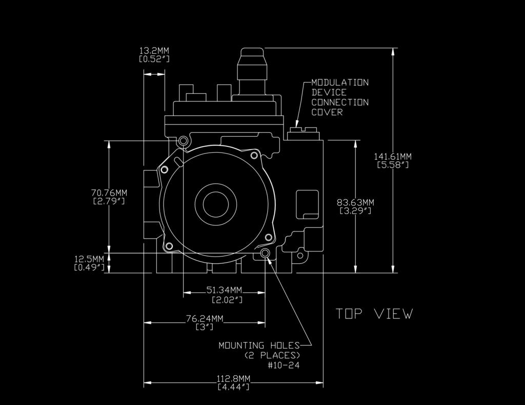
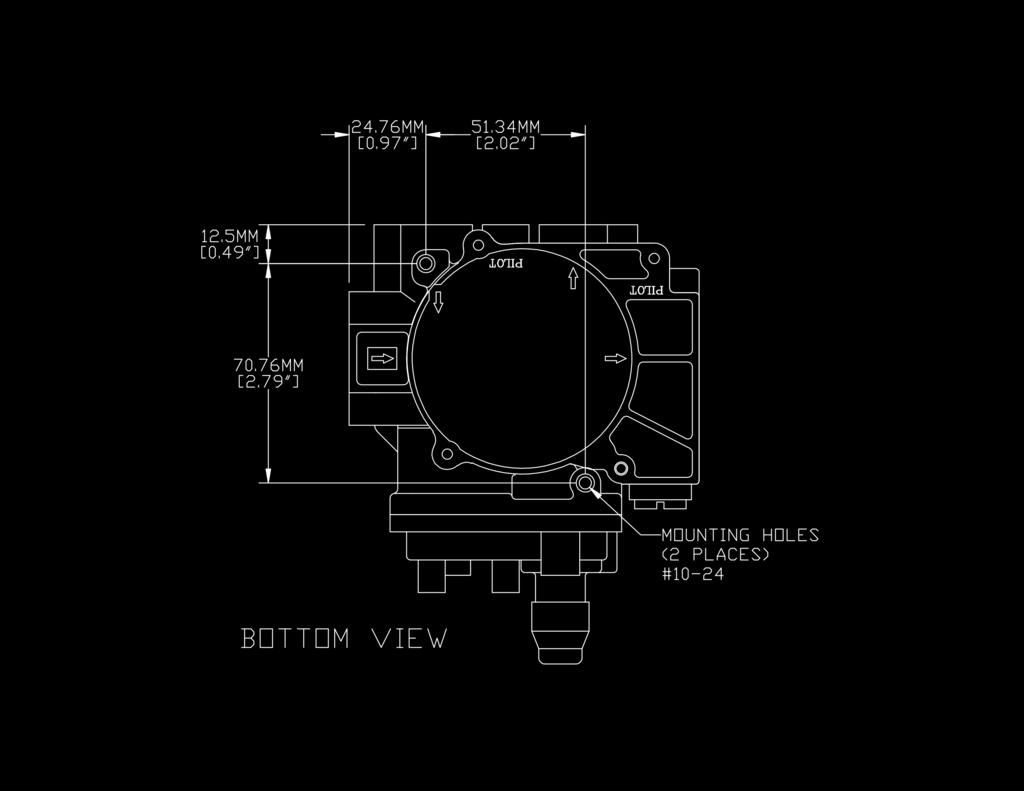
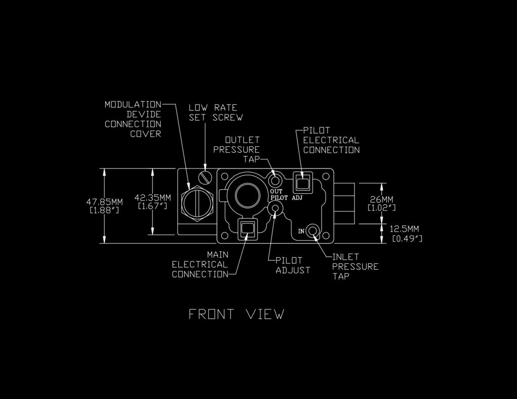
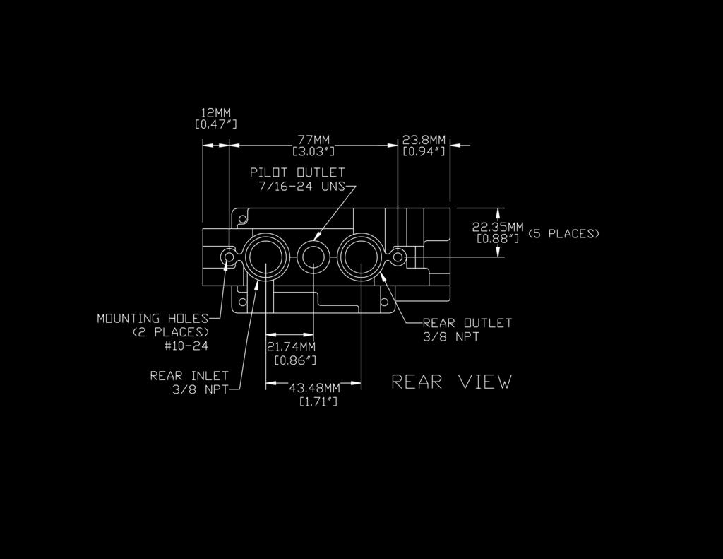
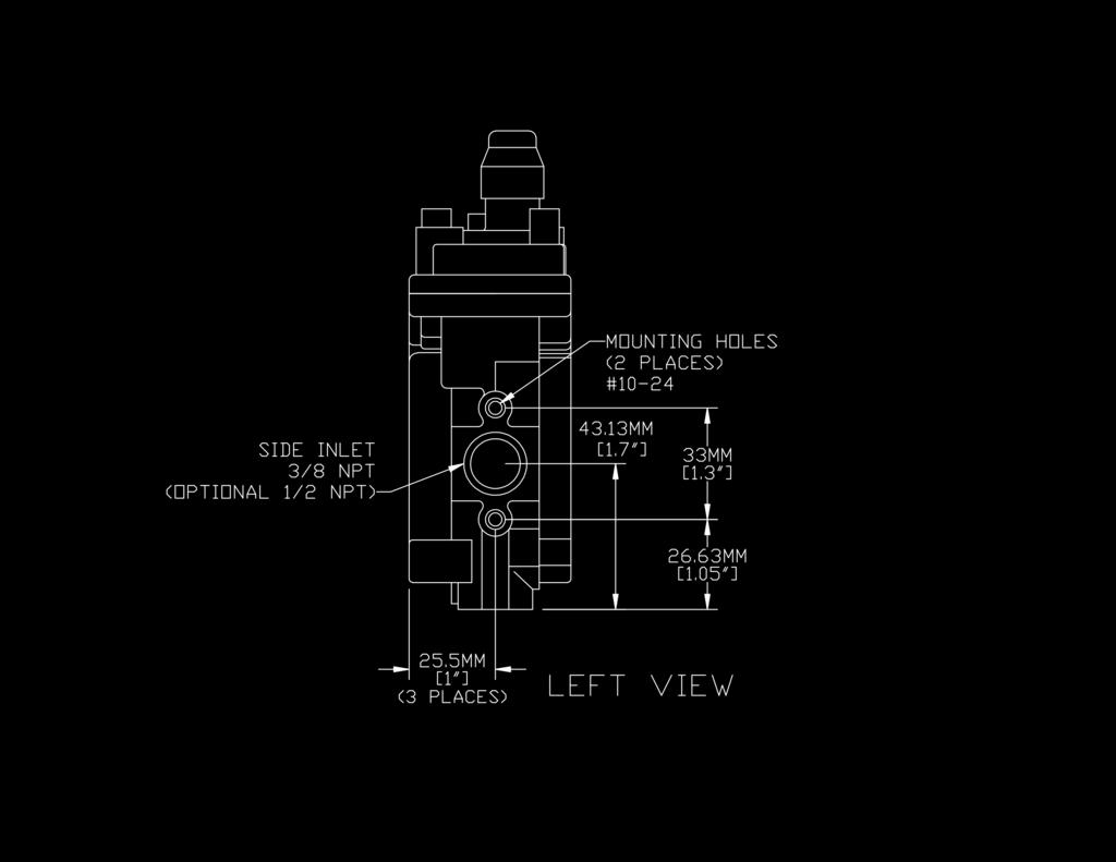
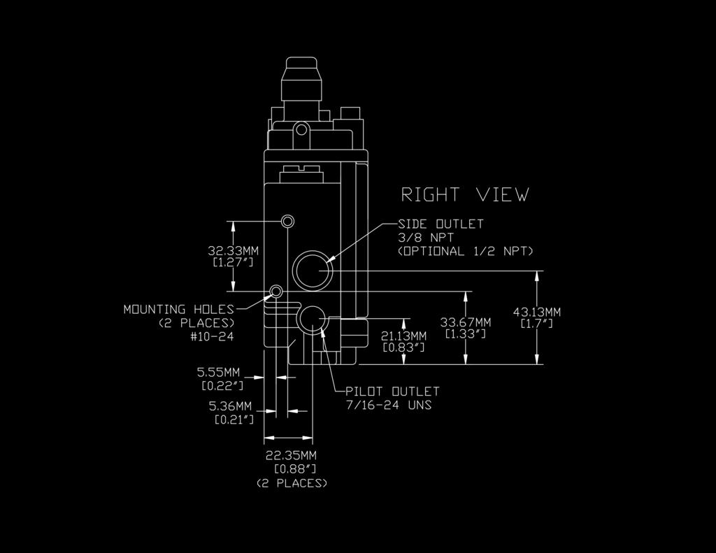
3 DIMENSIONS REV Page 3 of 11
4 INSTALLATION When Installing this Product. Read these instructions carefully. Failure to follow these instructions completely could damage the product or cause a hazardous condition. Check the ratings given in the instructions and on the product to make sure the AF-4000 Electronic Gas Control is suitable for your application. Installer must be a trained, experienced service technician. After installation is complete, check out product operation as provided in these instructions. Oxygen depletion hazard. Can cause injury or death due to asphyxiation. 1. Use only vented gas pilot assemblies on vented appliances. 2. Use only unvented pilot assemblies on unvented appliances. Fire or explosion hazard. Can cause property damage, servere injury or death.follow these warnings exactly: 1. Disconnect power before wiring to prevent electrical shock or equipment damage. 2. To avoid dangerous accumlation of fuel gas, turn off gas supply at the appliance service valve before starting installation, and perform a Gas Leak Test after installation is complete. 3. Always install the sediment tap in the gas supply line to prevent contamination of the gas control. 4. Do not force the gas control knob. Use only your hand to turn the gas control knob. Never use any tools. If the gas contron knob does not operate by hand, the gas control should be replaced by a qualified service technician. Force or any attempt to repair the gas control valve can result in fire or explosion. Location: Locate the AF-4000 gas control where it cannot be affected by steam cleaning, high humidity, dripping water, corrosive chemicals, dust or grease accumulation or excessive heat. To assure proper operation, follow these guidelines: 1. Locate gas control in well-ventilated area. 2. Mount gas control high enough to avoid exposure to flooding or splashing water. 3. Assure the ambient temperature does not exceed the ambient temperature ratings for each component. 4. Cover gas control if appliance is cleaned with water, steam, or chemicals or to avoid dust and grease accumulation. 5. Avoid locating gas control where exposure to corrosive chemical fumes or dripping water is likely. Install Piping to Gas Control: All piping must comply with the local codes and ordinances or with the National Fuel code (ANSI Z223.1 NFPA No. 54) which ever applies. Tubing installation must comply with approved standards and practices. 1. Use new, properly reamed pipe free from chips, When tubing is used, assure the ends are square, deburred and clean. All tubing bends must be smooth and without deformation. 2. Run pipe or tubing to the control. If tubing is used, obtain a tube-to-pipe coupling to connect the tubing to the control. 3. Install sediment trap in the supply line to the gas control. See Figure #1 Gas Leakage Hazard. Failure to follow precautions can result in a gas-filled work area. Shut off the main gas supply before removing end cap. Test for gas leakage when installation is complete. Figure #1 REV Page 4 of 11


 push in the Simple Rotary knob and rotate 90º.")

5 Installation of AF-4000 Control 1. Mount control 0 to 90 degrees in any direction, from the upright position of the gas control knob, including vertically. 2. Mount the control so gas flow is in the direction of the arrow on the side Figure #2 or back of the control. 3. Thread pipe 9/16 in. into the control. Do not inset deeper than 3/8 in. Valve distortion or malfunction can result if the pipe is inserted too deeply. 4. Apply a moderate amount of good quality pipe compound to pipe only, leaving two (2) end threads bare. On LP installations, use compound resistant to LP gas. See Figure #2 5. Remove plastic dust seals over the control Inlet and Outlet if necessary. 6. Connect pipe to control Inlet and Outlet. Use wrench on either side of the pipe outlet. See Figure #3 Converting the AF-4000 Natural to Propane Figure #3 The AF-4000 f i electronic r e control - valve p is convertable a from r natural t gas s to propane. gas c by a Simple o Rotary mknob located on the front (Face) of the valve. Note: Figure #4 1. Unscrew and remove the cover cap. Note: the position of the marker on the shaft of the Simple Rotary knob. This mark will point to NAT or LP that indicates the type of gas the valve is set on. 2. To convert the AF-4000 from the factory setting (NAT) push in the Simple Rotary knob and rotate 90º. Note: the marker will now point to LP and the shaft will stay in. 3. To convert the AF-4000 back to the factory setting (NAT) push in the Simple Rotary knob and rotate 90º. Note: the marker will now point to NAT and the shaft will stay out. 4. After the conversion has been made check the out let pressure with a manometer. The factory setting on the internal regulator is 3.50 wc natural and 10.5 wc propane. 5. Replace the cover cap. Use extreme caution when changing this Simple Rotary knob Figure #4 Spark to Pilot Burner Connections This gas control uses a spark to pilot burner assembly. The pilot gas connections are as follows: 1. Select the pilot outlet on the AF-4000 valve to be used (Side or back) connection. If the side connection is used, the plug will need to be moved to the back pilot conection. After the plug has been installed check for leaks with rich soap and water solution. REV Page 5 of 11
 modual Note: Figure #6. 2.")

 pin male connectors on the front (Face) of the AF-4000 electronic control valve Note: Figure # 7. 2.")
6 2. Connect the pilot tubing fitting into the gas control connection and tighten. (Use caution on brass connectors) Note: Figure #5 Wiring The Pilot 1. Connect the S & I wires from the pilot assembly to the S & I terminals on the (AF-4000 MOD) modual Note: Figure #6. 2. Route the S & I wires from the pilot assembly to the (AF-4000 MOD) module in an area that will be away from the pilot or main burner flame. AUX Connection 6 Volt DC Adaptor Power Connection Learn AUX POWER IPI 8 Pin IPI Connection Continuous Pilot Off/On Remote/Off ADJ. S I Figure #5 Figure #6 S Pilot Connection (AF-4000 MOD) Module Top I Pilot Connection Wiring The (AF-4000) Valve 1. Locate the (2) pin male connectors on the front (Face) of the AF-4000 electronic control valve Note: Figure # If the AF-4000 electronic control valve is eqiuped with a HI/LO solenoid, HI/LO DC motor drive, or HI/LO Step Motor locate the wiring connections on the HI/LO device Note: Figure #8 Hi Lo Optional Manual HI/LO Optional Step Motor HI/LO (AF-4000MOT) Optional HI/LO solenoid Optional Veriable HI/LO Figure #7 Figure # 8 Wiring The (AF-4000 MOD) Module 1. Locate the (AF-4000 MOD) module in an area that that will not exceed an ambient temperature of 150º F. 2. Locate all the connections on the (AF-4000 MOD) module Note: Figure #6. 3. Locate all the wire connections on the (8) pin connector wiring harness Note Figure #12. REV Page 6 of 11
7 4. Connect the (2) wires from the spark to pilot assembly to the terminals marked S & I on the (AF-4000 MOD) module Note location on Figure #9. 5. Connect the (8) pin female connector on the wiring harness to the (8) pin male connector on the (AF-4000 MOD) module Note location on Figure # Connect the black wire marked GROUND from the wiring harness to the appliance chassie. 7. Plug the (2) pin female connector marked PILOT (Orange & White wires) from the wiring harness to the (2) pin male connector on the front (Face) of the AF-4000 electronic control valve (Marked PILOT on the control valve) Note locations Figures #7 & # Plug the (2) pin female connector marked MAIN (Green & White wires) from the wiring harness to the (2) pin male conector on the front (Face) of the AF-4000 electronic control valve (Marked MAIN on the control valve) Note locations Figures #7 & # If a manual rocker or wall switch is used connect the (2) Brown wires marked SWITCH from the wiring harness to the switch Note marked wires Figure #12. Optional: If a 6 volt power supply is used connect the (2) 1/4 female terminals from the 6 volt transformer to the (2) 1/4 male terminals marked POWER on the module Note: location on Figure #11. Optional: If an AF-4000 BP battery pack is used follow the Wiring The (AF-4000 BP) Battery Pack section in these instructions. Continuous Pilot Off/On Switch Remote/Off Switch ADJ. Learn Button AUX Connection S Pilot Connection I Pilot Connection AF-4000 MOD Module Rt Side AF-4000 MOD Module Lt Side Figure # 9 Figure #10 6 Volt DC Adaptor Power Connection 8 Pin IPI Connection (2) open terminals (No Wires) 1/4 female terminal (Manual Switch) Brown Wire Brown Wire (2) White Wires Green Wire Orange Wire Black Wire 2 Pin connector (Main) 2 Pin connector (Pilot) (8) Pin Female Connector (White) 1/4 Fork terminal (Ground Wire) AF-4000 MOD Module End AF-4000 MOD 8 Pin Connector Wiring Harness Figure # 11 Figure #12 Special Features On The (AF-4000 MOD) Module The (AF-4000 MOD) module has (2) special features built into the system. CONTINUOUS PILOT FEATURE: This allows the user to change from a spark to pilot system to a standing pilot system for direct vent appliances during Cold Climate to keep the firebox warm. 1. There is a switch located on the side right side of the (AF-4000 MOD) module that reads CONTINUOUS PILOT ON/OFF this switch will allow the user to select the pilot mode of operation. Note: Figure #9 REV Page 7 of 11
8 2. When the continuous pilot switch is in the OFF position and the appliance on/off switch is turned ON the pilot will spark and light, and when the appliance on/off switch is turned OFF the pilot will shut OFF when the main burner shuts OFF. 3. When the continuous pilot switch is in the ON position and the appliance on/off switch is turned ON the pilot will spark and light, when the appliance on/off switch is turned OFF the pilot will stay ON when the main burner shuts OFF. This setting is generally used in Cold Climate to keep the firebox warm. 4. The CONTINUOUS pilot mode can also be activated by an (Optional) hand held Remote Control. REMOTE CONTROL FEATURE: The (AF-4000 MOD) module has a built in remote control receiver this allows the user to program a hand held remote transmitter, wireless wall mount thermostat or wireless wall mount switch to the appliance at any time during or after installation of the appliance. 1. There is a switch located on the right side of the (AF-4000 MOD) module that reads REMOTE/OFF. Note: Figure #9 2. When the remote/off switch is in the OFF position the appliance will operate from an appliance mounted rocker switch or wall switch connected to the (2) BROWN wires on the (AF-4000 MOD) Module. 3. When the remote/off switch is in the REMOTE position the appliance will operate from the (Optional) Remote Control transmitter wireless wall mount thermostat or wireless wall mount switch. Note: The AF-4000 MOD must be programmed to the (Optional) Remote Control transmitter wireless wall mount thermostat or wireless wall mount switch. 1. To program the AF-4000 MOD (Make sure the system is power) locate the learn button on the AF-4000 MOD (Note Figure #10) press and release the learn button there will be a beep sound from the AF-4000 MOD then press any key on the remote transmitter. Once the AF-4000 MOD internal receiver accepts the transmitter code there will be a series of confirming beeps. 2. The remote system is ready for use. AF-4000 MOD (Options) The AF-4000 f i MOD r can e be powered - by p two (2) a different r scores t (1) is s a standard. 110 c volt AC o to 6.0 volt mdc adaptor. This adaptor is connected to the AF-4000 MOD by connecting the (2) 1/4 female terminals from the adaptor to the (2) 1/4 male terminals located on the AF-4000 MOD marked (power). Using the 6.0 volt adaptor (only) without using the AF-4000 BP battery pack the system will not have a back up power scores during a power outages. Wiring The (AF-4000 BP) Battery Pack 1. Locate the (AF-4000 BP) battery pack in an area that that will not exceed an ambient temperature of 130º F (Batteries exposed to temperatures above 120ºF will drain voltage and shorten battery life). 2. Locate the AUX connection and the optional Hi/Lo wire connections on the (AF-4000 BP) battery pack Note: Figure # Locate the wire connections on the (4) pin connector wiring harness and the solenoid or DC motor drive wiring harness shown in Note Figure # Install (4) AA alkaline batteries in the (AF-4000 BP) battery pack. 5. Plug one of the (4) pin female connector on the (AF-4000 BP) battery pack wiring harness into the (4) pin male connector located on the back of the battery pack Note location shown in Figure # Plug the other (4) pin male connector on the (AF-4000 BP) battery pack wiring harness into the (4) pin female AUX connector located on the (AF-4000 MOD) module shown Note location shown in Figure # If the model of AF-4000 electronic control valve has a Hi/Lo solenoid or DC motor drive use the solenoid or DC motor drive wiring harness shown in Figure #13 Note: If the Hi/Lo Step Motor (Model AF-4000MOT) has been selected the this requires a unique operating control transmitter and receiver specifically set-up for the desired Hi/Lo increments required by the burner installed in the appliance that the AF-4000 valve system is used on. Wiring The Optional Hi/Lo 1. Connect the striped ends of the RED and BLACk wires on solenoid or DC motor drive wiring harness to the screw terminals located on ther top of the (AF-4000 BP) battery pack Note: location in Figure #13 2. Connect the (2) 1/4 female terminals on the solenoid or DC motor drive wiring harness to the matching color (RED & BLACK) 1/4 male terminals on the Hi/Lo solenoid or the Hi/Lo DC motor drive. Note: locations in Figure #8 & # Note the Latching Solenoid mode and DC Motor Drive mode switch located on the front of the (AF-4000 BP) battery pack in Figure #13. REV Page 8 of 11
9 4. Use the Latching Solenoid mode when connecting to a Hi/Lo solenoid and the DC Motor Drive mode when using the Hi/Lo DC motor drive. 5. When the (AF-4000MOT) Hi/Lo Step Motor is used the 4 pin connector from the step motor connects directly into the 4 pin AUX connection on the (AF-4000MOD) Requires 4-AA 1.5V alkaline batteries HI/LO Connection RED Wire HI/LO Connection BLACK Wire Latching Solenoid DC Motor Drive Module Battery Pack Battery cover slides on/off Latching Solenoid DC Motor Drive Module Battery Pack Front HI/LO Connection BLACK Wire HI/LO Connection RED Wire Figure #13 1/4 Female Terminals RED Wire Striped & Tinned Black Wire 4 Pin AUX Connection Solenoid or DC motor Drive Wiring Harness 18 (4) Pin AUX Connectors Module Battery Pack Back Battery Pack to Module Wiring Harness Direct Spark Ignition Operation (DSI) (optional) The AF-4000 series gas valve may be used in conjunction with the AF-5000MOD direct spark ignition control for DSI operation. 1. For operation with the direct spark ignition control module (AF-5000MOD), both pilot outlets (side and rear) must be plugged. 2. Follow the AF-5000MOD control instructions for wiring and additional directions on using the AF-4000 series gas valve in a direct spark ignition configuration. Fire or explosion hazard. Can cause property damage, severe injury or death. 1. Stand away from the main burner while lighting, Hidden gas leaks can cause flashbacks in the appliance. 2. Check for gas leaks with rich soap and water solution any time work is done on a gas system. Gas Leak Test 1. Paint the pipe connectors upstream of the gas control with rich soap and water solution, Bubbles indicate a gas leak. 2. If a leak is detected, tighten the pipe connections. 3. Light the main burner. 4. With the main burner in operation, paint the pipe joints (including adapters) with rich soap and water solution. 5. If another leak is detected, tighten the adapter screws, joints, and pipe conections. 6. Replace part if leak cannot be stopped. REV Page 9 of 11
10 Equipment Danger Hazard. Improper adjustment of gas input and burner can cause carboning and/or unnecessary shutdown of the system. 1. Do not exceed the input rating stamped on the appliance nameplate, or manufacture recommended burner orifice pressure for size orifice(s) used. Be sure primary air supply to the main burner is properly adjusted for complete combustion. Follow the instructions of the appliance manufacturer. 2. IF CHECKING GAS INPUT BY CLOCKING GAS METER: Be sure there is no gas flow through the meter other that to the appliance being checked. Other appliances must remain off with the pilots extinguished (or the consumption must be deducted from the meter reading). Convert the flow rate to Btuh as described in the GAS Controls Handbook, from , and compare to the Btuh input rating on the appliance nameplate. 3. IF CHECKING GAS INPUT WITH MANOMETER: Both the input and output pressure taps have a captive screw. To measure the pressure of the tap, loosen, but do not remove the captive screw, attach a plastic tube with a 1/3 in. shell I.D. and connect the manometer. After checking the pressure, turn the gas control knob to the OFF position, Before opening the outlet pressure tap, be sure the gas control knob is in the OFF position. Before opening the inlet pressure tap, shut the gas supply at the manual valve in the gas piping to the appliance or, for LP, at the tank. Repeat the Gas LeakTest at the pressure tap with mainburner operating. MAINTENANCE Fire or explosion hazard. Can cause property damage, severe injury or death. Do not attempt to take a part the gas control or to clean it. Improper assembly and cleaning can cause unreliable operation. Regular preventive maintenance is important in applications that place a heavy load on the system such as those used in commerical cooking, agricultural, and industrial application because: In many such applications, particularly commerical cooking, the equipment operates 100,000 to 200,000 cycles per year. Such heavy cycling can wear out the gas control in one to two years. Exposure to water, dirt, chemicals, and heat can damage the gas control and shut down the control system. The maintance program should include regular checkout of the system as outlined in the Checkout section, and checkout the system as discribed in the appliance manufacturers literature. Maintance frequency must be determined individually for each application, Some considerations are: Cycling frequency. Appliances that may cycle 20,000 times annually should be checked monthly. Intermittent use. Appliances that are used seasonally should be checked before shutdown and again before the next use. Consequence of unexpected shutdown, where the cost of an unexpected shutdown would be high, and the system should be checked more often. Dusty, wet, or corrosive envirornment. Because these environments can cause the gas control to deteriorate more rapidly, the system should be checked more often. Any control should be replaced if it does not perform properly on checkout or service. In addition, replace any module if it is wet or looks like it has been wet. SERVICE Fire or explosion hazard. Can cause property damage, severe injury or death. Do not disassemble the gas control; it contains non replaceable components. Attempted disassembly or repair can damage the control. Fire or explosion hazard. Can cause property damage, severe injury or death. Exactly follow the warnings and the lighting instructions. REV Page 10 of 11
11 1. Before lighting, smell around the appliance area for gas. If the appliance uses LP (bottled) gas, be sure to smell next to the floor because LP gas is heavier than air. If you smell gas, immediately shut off the manual valve in the gas piping to the appliance or, on LP at the tank. Do not try to light any appliance. Do not touch any electrical switch or use the phone. Leave the building and call your gas supplier. If your gas supplier cannot be reached, call the fire department. 2. The gas conrol must be replaced if it has been flooded with water. Call a qualified service technician. 3. The gas control is a safety device. It must be replaced in case of any physical damage such as bent terminals, missing parts, stripped threads, or evidence of exposure to heat. IMPORTANT: Follow the operating instructions provided by the manufacturer of your heating appliance. TROUBLESHOOTING IMPORTANT: An experienced qualified service technician should perform trouble-shooting procedures. If the pilot will not stay lit: 1. Confirm that the S wire and the I wire are properly connected to the (AF-4000 MOD) modual S and I terminals. Note: Figure #7 for terminal locations. 2. Confirm that the Spark to Pilot burner is properly grounded to the AF-4000 gas control valve and to the (AF-4000 MOD) module. 3. Check the power sorce (1) the 6-volt power adaptor or the (AF-4000 BP) battery pack connections and condition of batteries. 4. Optional check the position of the CONTINUOUS PILOT switch on the (AF-4000 MOD) module If main burner does not come ON when the manual switch or remote control is turned ON: 1. Confirm that the pilot sparks and lights. 2. Check the (2) pin plastic connectors that plug in the face of the AF-4000 gas control valve Note: Figure #6 3. Confirm that theaf-4000 gas control is properly grounded to the (AF-4000 MOD) module. Limited Warranty American Flame, Inc. warrants the AF-4000 Valve series for 12 months from the date of purchase or installation to the original purchaser to be free from defects in materials and workmanship. Damage to the AF-4000 Valve caused by accident, misuse, abuse, or installation error, whether performed by a contractor, service company, or owner, is not covered by this warranty. American Flame will not be responsible for labor charges and/or damage incurred in installation, repair, replacement, or for incidental or consequential damage. Some states, provinces, and nations do not allow exclusion or limitations of incidental or consequential damages, so the above limitations or exclusions may not apply. This warranty gives you specific legal rights. You may also have other rights that vary by state, province, or nation. American Flame, Inc Conservation Way Fort Wayne, IN Phone (260) Fax (260) REV Page 11 of 11
MODERUSTIC Battery Operated Remote Control Electronic Safety Pilot System IPI Intermittent Pilot Light For Fire Pits or Fireplaces
 MODERUSTIC Battery Operated Remote Control Electronic Safety Pilot System IPI Intermittent Pilot Light For Fire Pits or Fireplaces Model: AFVK-SP-MH/L Remote flame height adjustment DC Motor Drive Hi,
Models: AFVK-SP-SPLIT AFVK-SP-H/L-SPLIT AFVK-SP-MH/L-SPLIT INSTALLATION AND OPERATING INSTRUCTION
 Electronic Safety Pilot System for Vented Gas Logs Models: AFVK-SP-SPLIT AFVK-SP-H/L-SPLIT AFVK-SP-MH/L-SPLIT IF YOU CANNOT READ OR UNDERSTAND THESE INSTALLATION INSTRUCTIONS DO NOT ATTEMPT TO INSTALL
Remote Flame Height Adjustment Solenoid Hi to Lo (Natural/Propane Gas) Remote Flame Height Adjustment DC Motor Drive Hi to Lo (Natural/Propane Gas)
 Remote Flame Height Adjustment DC Motor Drive Hi to Lo (Natural/Propane Gas)") N N H L N H L A M E R C A N F L A M E A F Electronic Safety System Models: AFVK-SP Manual Flame Height Adjustment Hi to Lo (Natural/Propane Gas) AFVK-SP-H/L AFVK-SP-MH/L (SPLPK-18 or SPLPK-24 Kits are
N N H L N H L A M E R C A N F L A M E A F Electronic Safety System Models: AFVK-SP Manual Flame Height Adjustment Hi to Lo (Natural/Propane Gas) AFVK-SP-H/L AFVK-SP-MH/L (SPLPK-18 or SPLPK-24 Kits are
Safety Pilot System For Vented Gas Logs
 HI A M E R I C A N F L A M E A F Models: AFVK AFVK-H/L AFVK-VH/L Safety Pilot System For Vented Gas Logs Manual Flame Height Adjustment High to Low (Natural/Propane Gas) Remote Flame Height Adjustment
Electronic Safety Pilot System for Vented Gas Logs Models: AFVK-SP AFVK-SP-MH/L
 L H L H L A M E R C A N F L A M E A F Electronic Safety System for Vented Gas Logs Models: AFVK-SP AFVK-SP-H/L AFVK-SP-MH/L F YU CANNT READ R UNDERSTAND THESE NSTALLAT NSTRUCTS D NT ATTEMPT T NSTALL R
B21 Series BASOTROL Gas Valve
 Installation Instructions B21 Issue Date September 19, 2017 Installation IMPORTANT: These instructions are intended as a guide for qualified personnel installing or servicing BASO Gas Products. Carefully
MODEL: 1410-A INSTALLATION AND OPERATION INSTRUCTIONS
 INTRODUCTION TRANSMITTER MODEL: 1410-A INSTALLATION AND OPERATION INSTRUCTIONS IF YOU CANNOT READ OR UNDERSTAND THESE INSTALLATION INSTRUCTIONS DO NOT ATTEMPT TO INSTALL OR OPERATE This remote control
MODEL RVS304. REMOTE CONTROLLED SAFETY PILOT KIT Supplemental Installation Instructions for use with Natural Gas Log Sets
 MODEL RVS304 REMOTE CONTROLLED SAFETY PILOT KIT Supplemental Installation Instructions for use with Natural Gas Log Sets NOTE: This kit is for both Natural Gas and LP Gas applications. For LP (Propane)
Gas Conversion Kits and Instructions
 General and Warnings FOR YOUR SAFETY WHAT TO DO IF YOU SMELL GAS Do not try to light any appliance. Do not touch any electrical switch; do not use any phone in your building. Leave the building immediately.
ROBERT H. PETERSON CO. AUTOMATIC REMOTE LIGHTING SAFETY PILOT SYSTEM WITH VARIABLE FLAME-HEIGHT REMOTE FOR NATURAL OR PROPANE GAS. Model APK-17(M)(P)
(P)") ROBERT H. PETERSON CO. Owner s Manual AUTOMATIC REMOTE LIGHTING SAFETY PILOT SYSTEM WITH VARIABLE FLAME-HEIGHT REMOTE FOR NATURAL OR PROPANE GAS FEATURES: CONTROL OPERATED ON/OFF VARIABLE FLAME-HEIGHT
ROBERT H. PETERSON CO. Owner s Manual AUTOMATIC REMOTE LIGHTING SAFETY PILOT SYSTEM WITH VARIABLE FLAME-HEIGHT REMOTE FOR NATURAL OR PROPANE GAS FEATURES: CONTROL OPERATED ON/OFF VARIABLE FLAME-HEIGHT
SAVANNAH EI & DELUXE SYSTEM TROUBLE SHOOTING GUIDE
 SAVANNAH EI & DELUXE SYSTEM TROUBLE SHOOTING GUIDE ***PLEASE MAKE SURE TO LEARN THE REMOTE TO THE SYSTEM (REFER TO PG 6) AND CHECK THE BATTERIES FIRST!!! (American Flame AF-4000 Series) Intermittent Pilot
INSTALLATION INSTRUCTIONS FOR PCBM-36C CONVERSION KIT From Natural Gas to Propane/LP Gas
 INSTALLATION INSTRUCTIONS FOR PCBM-36C CONVERSION KIT From Natural Gas to Propane/LP Gas For Use When Converting Models CB36N and VCB36N This conversion kit must be installed by a qualified service agency.
Natural Gas Conversion Instructions for
 CONVERSION INSTRUCTIONS Natural Gas Conversion Instructions for WM16-GBC1405WV WARNING FOR YOUR SAFETY: For Outdoor Use Only (outside any enclosure) WARNING FOR YOUR SAFETY: 1. Improper installation, adjustment,
MODEL: RCTS-MLT III INSTALLATION AND OPERATION INSTRUCTIONS
 INTRODUCTION MODEL: RCTS-MLT III INSTALLATION AND OPERATION INSTRUCTIONS IF YOU CANNOT READ OR UNDERSTAND THESE INSTALLATION INSTRUCTIONS DO NOT ATTEMPT TO INSTALL OR OPERATE This remote control system
BG1600M Intermittent Pilot Ignition Control
 Installation Instructions Issue Date March, 00 BG600M Intermittent Pilot Ignition Control Application The BG600M Intermittent Pilot Ignition Control is a safety control designed for indirect burner ignition
CAUTION WARNING WARNING PROFLAME 2 UPGRADE KIT RX RX 300 NG/LP. Installation & Maintenance Manual
 & Maintenance Manual PROFLAME 2 UPGRADE KIT + RX 300 NG/LP Upgrade Kit NG/LP Proflame 2 (Basic to Full Load with Remote) THIS KIT IS FOR USE WITH THE FOLLOWING MODELS: RX200: B34DT-2-F : B34 TOP VENT,
American Flame AF-4000 Series Intermittent Pilot Ignition System Trouble Shooting Guide
 American Flame AF-4000 Series Intermittent Pilot Ignition System Trouble Shooting Guide Contents IPI System Overview Pgs. 2-5 Module Audible Alerts Pgs. 6-7 Module Error Codes Pgs. 8-9 Extension Module
AUTOMATIC REMOTE CAPABLE SAFETY PILOT SYSTEM
 OWNER S MANUAL AUTOMATIC REMOTE CAPABLE SAFETY PILOT SYSTEM PRE-ASSEMBLED READY FOR INSTALLATION FEATURES: NON-STANDING FLAME-SENSING PILOT MANUAL SWITCH ON/OFF OPTIONAL REMOTE CONTROL BATTERY OPERATION
E Series CE Approved Intermittent Pilot Ignition Control
 Installation Instructions Issue Date January 11, 2013 E Series CE Approved Intermittent Pilot Ignition Control Application The E Series CE Approved Intermittent Pilot Ignition Control is a safety control
AUTOMATIC REMOTE CAPABLE SAFETY PILOT SYSTEM
 OWNER S MANUAL AUTOMATIC REMOTE CAPABLE SAFETY PILOT SYSTEM PRE-ASSEMBLED READY FOR INSTALLATION (Suitable for G4, G45, and PB series burners) (Sizes 12"- 24" for natural; 12"- 36" for propane gas) MODEL
Troubleshooting Guide
 Troubleshooting Guide IntelliFire Plus Ignition System *For authorized gas technicians use only. 9/15/2011 Hearth & Home Technologies Page1 Guide Table of Contents Introduction. 3 Tools and Instruments...
CHALLENGER Propane to Natural Gas Instructions
 Kit Part Number: CCRKIT02 Kit Includes: - Rating Label - (3) Natural Gas Orifices - T-15 Torx Wrench Recommended Tools: - Phillips-Head Screwdriver - Standard Adjustable Wrenches - Calibrated Combustion
Robert H. Peterson Co.
 RHP Robert H. Peterson Co. OWNER S MANUAL AUTOMATIC REMOTE CAPABLE SAFETY PILOT SYSTEM PRE-ASSEMBLED READY FOR INSTALLATION (Suitable for G4, G45, and PB series burners) (Sizes 12"- 24" for natural; 12"-
INSTALLATION AND OPERATION INSTRUCTIONS
 120 Cat. No. H8863 Model: WS-S-TMR INSTALLATION AND OPERATION INSTRUCTIONS IF YOU CANNOT READ OR UNDERSTAND THESE INSTALLATION INSTRUCTIONS DO NOT ATTEMPT TO INSTALL OR OPERATE INTRODUCTION This remote
Applies to: Models F, B, FE, and BE with spark pilot
 Form CP-F/B-GC (11/17) R8 Obsoletes Form CP-F/B-GC (Version A.2) Gas Conversion Kits and Instructions Applies to: Models F, B, FE, and BE with spark pilot NOTE: Units with standing (match - lit) pilots
MODEL NUMBER: MEDIUM DUTY ONBOARD AIR SYSTEM
 MODEL NUMBER: 10003 MEDIUM DUTY ONBOARD AIR SYSTEM IMPORTANT: It is essential that you and any other operator of this product read and understand the contents of this manual before installing and using
X4 Installation and Operation Manual - POWER FLAME INCORPORATED
 7.13.2 Set the burner s combustion air inlet damper to the approximate setting as shown in this manual for the desired firing rate. Also, verify that the correct main orifice is installed in the main orifice
Model: 1001TH - A INSTALLATION AND OPERATING INSTRUCTIONS
 Model: 1001TH - A INSTALLATI AND OPERATING INSTRUCTIS IF YOU CANNOT READ OR UNDERSTAND THESE INSTALLATI INSTRUCTIS DO NOT ATT TO INSTALL OR OPERATE INTRODUCTI This remote control system was developed to
G76x Direct Spark Ignition Controls
 Installation Sheets Manual 121 Gas Combustion Combination Controls and Systems Section G Technical Bulletin G76x Issue Date 0400 G76x Direct Spark Ignition Controls Figure 1: G76x Direct Spark Ignition
OWNER S MANUAL: Model # JGSBSEAR Searing Burner Station
 JACKSON GRILLS INC. #106-2480 Mt. Lehman Rd. Abbotsford, BC V4X 2N3 TEL: 1(888) 287-3333 FAX: 1(877) 855-5373 SUPPORT: support@jacksongrills.com WEB SITE: www.jacksongrills.com OWNER S MANUAL: Model #
Q35 Series Automatic Vent Damper System
 Installation Sheets Manual 121 Energy Conservation and Miscellaneous Kits Section Q Technical Bulletin Q35 Issue Date 0999 Q35 Series Automatic Vent Damper System Figure 1: Q35 Automatic Vent Damper System
OWNER'S MANUAL WARNING DANGER. Propane cylinders sold separately. The propane cylinder must be disconnected when this firebowl is not use.
 OWNER'S MANUAL READ BEFORE USE! Model No.: BH5003-3 Style No.: 66646 For Outdoor Use Only! Use Propane Gas Only! Propane cylinders sold separately. USE PROPANE GAS ONLY! -Do not store or use gasoline or
G600 Series Replacement Intermittent Pilot Ignition Controls
 Installation Instructions G600 Issue Date 0601 G600 Series ment Intermittent Pilot Ignition Controls Installation IMPORTANT: These instructions are intended as a guide for qualified personnel installing
40041 Heavy Duty ADA System with Booster Bracket for JK Heavy Duty ADA System with Booster Bracket for 2012 to Current JK
 40041 Heavy Duty ADA System with Booster Bracket for 2007-2011 JK 40044 Heavy Duty ADA System with Booster Bracket for 2012 to Current JK 40049 Heavy Duty ADA System Universal for all vehicles (booster
HEAVY DUTY ONBOARD AIR SYSTEM PART NO
 IMPORTANT: It is essential that you and any other operator of this product read and understand the contents of this manual before installing and using this product. SAVE THIS MANUAL FOR FUTURE REFERENCE
GAS FIRED BROILERS 36W36 235W36 43W36 243W36 136W36 C36 V136W36 C45
 DESIGN C E R TI F I E D THE MONTAGUE CO. SERVICE & PARTS MANUAL GAS FIRED BROILERS 36W36 235W36 43W36 243W36 136W36 C36 V136W36 C45 NOTICE This manual is prepared for the use of Service Technicians and
VQ400M SERIES CLASS A COMBINATION VALVES PRODUCT HANDBOOK APPLICATION
 VQ400M SERIES PRODUCT HANDBOOK APPLICATION The VQ400M Series class A safety combination valves are used for control and regulation of gaseous fluids in gas power burners, atmospheric gas boilers, melting
HEAVY DUTY ONBOARD AIR SYSTEM
 HEAVY DUTY ONBOARD AIR SYSTEM PART NO. 10005 IMPORTANT: It is essential that you and any other operator of this product read and understand the contents of this manual before installing and using this
Troubleshooting Electronic Ignition
 Troubleshooting Electronic Ignition Bob Wise CVC Coaching This session is designed to provide a broad approach to troubleshooting electronic ignition systems. Various hearth electronic systems will be
G72x Series Direct Spark Ignition Controls
 Installation Sheets Manual 121 Gas Combustion Combination Controls and Systems Section G Technical Bulletin G72x Issue Date 1299 G72x Series Direct Spark Ignition Controls Figure 1: G72x Direct Spark Ignition
INSTALLATION DATA 712 Series Pilot
 INSTALLATION DATA 712 Series Pilot Ignition Systems (FLAME RECTIFICATION) LOCKOUT MODEL 712-005 712-006 712-008 712-009 NON-LOCKOUT MODELS 712-005 712-016 712-017 712-019 712-022 CSA DESIGN CERTIFIED TO
VE Series. Class "A" Gas Valves. Product handbook APPLICATION CONTENTS. General. Technical. Installation and operation. Various
 Class "A" Gas Valves Product handbook APPLICATION These series class A gas valves are used for control and regulation of gaseous fluids in gas power burners, atmospheric gas boilers, melting furnaces,
5270 Edison Ave., Chino, CA (Tel) (Fax)
 (Fax)") 5270 Edison Ave., Chino, CA 91710 (Tel) 800-790-1299 (Fax) 909-718-1949 NOTICE Dear Customers: Thank you for choosing our barbeque grill and hope that you enjoy our product. Our gas valves and components
5270 Edison Ave., Chino, CA 91710 (Tel) 800-790-1299 (Fax) 909-718-1949 NOTICE Dear Customers: Thank you for choosing our barbeque grill and hope that you enjoy our product. Our gas valves and components
MEDIUM DUTY ONBOARD AIR SYSTEM
 MEDIUM DUTY ONBOARD AIR SYSTEM PART NO. 10003 IMPORTANT: It is essential that you and any other operator of this product read and understand the contents of this manual before installing and using this
AUTOMATIC REMOTE LIGHTING SAFETY PILOT SYSTEM FOR NATURAL OR PROPANE GAS EPK-1 PILOT KITS
 INSTALLATION & OWNER S MANUAL AUTOMATIC REMOTE LIGHTING SAFETY PILOT SYSTEM FOR NATURAL OR PROPANE GAS Models: EPK-1(M)(P) FEATURES: INTERMITTENT PILOT IGNITION NON-STANDING FLAME-SENSING PILOT MANUAL
INSTALLER MANUAL USER MANUAL. Contents
 Installation & user manual two way Contents INSTALLER MANUAL Important information General 1. Technical data 2. Description Installation: 1. Positioning the unit 2. Connection. 3. Parts description. 4.
GSL Electronics Modified Sine Wave Power Inverters
 GSL Electronics Modified Sine Wave Power Inverters Congratulations on choosing one of our Modified Sine Wave Inverters for your application. There are 6 models in the range, which will meet most of your
Air-Operated Waste Oil Drainer
 Air-Operated Waste Oil Drainer 20-Gallon Tank Owner s Manual WARNING: Read carefully and understand all ASSEMBLY AND OPERATION INSTRUCTIONS before operating. Failure to follow the safety rules and other
Outdoor Fire Pit Installation and Operating Instructions
 MODELS: SFRSR19DSI (19-inch Round Fire Pit) SFRSR25DSI (25-inch Round Fire Pit) MODELS: SFRSS20DSI (20-inch Square Fire Pit) SFRSS26DSI (26-inch Square Fire Pit) Outdoor Fire Pit Installation and Operating
Note: An arrow ( ) found in the text signifies change in content.
 found in the text signifies change in content.") Installation Instructions LPK-OH - LEGACY/PHOENIX NG to LP Gas Conversion Kit Models: LEGACY42-IFT PHOENIX42-IFT WARNING: This conversion kit shall be installed by a qualified service agency in accordance
Installation Instructions LPK-OH - LEGACY/PHOENIX NG to LP Gas Conversion Kit Models: LEGACY42-IFT PHOENIX42-IFT WARNING: This conversion kit shall be installed by a qualified service agency in accordance
VQ400M SERIES CLASS A COMBINATION VALVES INSTRUCTION SHEET APPLICATION
 VQ400M SERIES INSTRUCTION SHEET APPLICATION The VQ400M Series class A safety combination valves are used for control and regulation of gaseous fluids in gas power burners, atmospheric gas boilers, melting
AUTOMATIC REMOTE LIGHTING SAFETY PILOT SYSTEM WITH VARIABLE FLAME-HEIGHT REMOTE FOR NATURAL OR PROPANE GAS APK-17 PILOT KITS
 INSTALLATION & OWNER S MANUAL AUTOMATIC REMOTE LIGHTING SAFETY PILOT SYSTEM WITH VARIABLE FLAME-HEIGHT REMOTE FOR NATURAL OR PROPANE GAS Models: APK-17(M)(P) FEATURES: CONTROL OPERATED ON/OFF VARIABLE
Installation Instructions for Aux 101 Kit A044Z055
 Instruction Sheet 7-2013 Installation Instructions for Aux 101 Kit A044Z055 1 Introduction The information contained within is based on information available at the time of going to print. In line with
Q345A, Q3451, Q3481, Q348A, Q348B, Q362A, Q373A, Q381A and Q3452 Intermittent Pilot Burner/Igniter-Sensors
 QA, Q, Q8, Q8A, Q8B, Q6A, QA, Q8A and Q Intermittent Pilot Burner/Igniter-Sensors FEATURES PRODUCT DATA QA Q,Q8 Q8A,B Q6A QA QA, Q8A, Q8B and QA Intermittent Pilot Burner/Igniter-Sensors are compatible
Hydraulic Immediate Need Power Pack
 Safety, Operation, and Maintenance Manual WARNING Improper use of this tool can result in serious bodily injury This manual contains important information about product function and safety. Please read
Innovations in Remote Controls
 Innovations in Remote Controls Terry Brumbaugh SkyTech Products Group This session will cover various types of remote controls that are used in the hearth industry. From ultra-sonic remotes to infrared
Outdoor Thermocouple Flame Sense (TFS) Linear Fire Pits Installation and Operating Instructions
 Linear Fire Pits Installation and Operating Instructions") MODELS MH# 60069 Natural Gas Description Propane FPB-24LTFS-N 24 Linear Pan & Burner FPB-24LTFS-P FPB-30LTFS-N 30 Linear Pan & Burner FPB-30LTFS-P FPB-36LTFS-N 36 Linear Pan & Burner FPB-36LTFS-P Outdoor
MODELS MH# 60069 Natural Gas Description Propane FPB-24LTFS-N 24 Linear Pan & Burner FPB-24LTFS-P FPB-30LTFS-N 30 Linear Pan & Burner FPB-30LTFS-P FPB-36LTFS-N 36 Linear Pan & Burner FPB-36LTFS-P Outdoor
VQ400M SERIES CLASS A COMBINATION VALVES PRODUCT HANDBOOK APPLICATION
 VQ400M SERIES PRODUCT HANDBOOK APPLICATION The VQ400M Series class A safety combination valves are used for control and regulation of gaseous fluids in gas power burners, atmospheric gas boilers, melting
G196 Series BASOTROL Redundant Combination Gas Valve with Manual Shutoff Valve
 Product Bulletin Issue Date March 13, 2013 G196 Series BASOTROL Redundant Combination Gas Valve with Manual Shutoff Valve The G196 Series valves use the reliable valve body and magnetic operators from
Troubleshooting Guide
 Troubleshooting Guide *For Authorized Gas Technicians Use Only* 1 Table of Contents Introduction 3 Tools and Instruments 4 Intellifire Component Parts 5 Intellifire Basics 7 Problem: The Ignitor makes
SERVICE MANUAL RRG SERIES HEAVY DUTY GAS GRIDDLE - NOTICE - ML ML ML RRG Shown
 SERVICE MANUAL RRG SERIES HEAVY DUTY GAS GRIDDLE 24RRG 36RRG 48RRG 60RRG ML-135339-00024 ML-135340-00036 ML-135341-00048 ML-135342-00060 24RRG Shown - NOTICE - This Manual is prepared for the use of trained
Owner s Guide ca4053 ca4553
 PROFESSIONAL SERIES Owner s Guide ca4053 ca4553 Remote Start System IMPORTANT NOTE: The operation of the Security and Convenience System as described in this manual is applicable to most vehicles. However,
Info 110 4/98. RatioMatic Burners. RM Series version through 600 Sizes. 750 through 2000 Sizes
 Info 110 4/98 RatioMatic Burners RM Series version 1.01 50 through 600 Sizes 750 through 2000 Sizes For Ratiomatic Serial Numbers 95-5500 and Above Version 1.01 7/97 Contents 1.0 Operating Parameters &
GEMINI GAS CONTROL PRODUCT INFORMATION
 GEMINI GAS CONTROL PRODUCT INFORMATION The Gemini (6G) combination gas control valve is a versatile multifunction control designed to meet the requirements for use with non-piloted intermittent ignition
DIRECT-DRIVE PRESSURE WASHERS
 DIRECT-DRIVE PRESSURE WASHERS PJG SERIES PRESSURE WASHER MANUFACTURED BY: PJG-2002B PJG-2502-6.5B PJG-3002B PJG-4002B INTRODUCTION Thank you for purchasing a Mancorp Pressure Washer. This manual covers
BGD278 Series BASOTROL CE Approved Gas Valve
 Product Bulletin Issue Date November 16, 2012 BGD278 Series BASOTROL CE Approved Gas Valve The BGD278 Series gas valve is a combination main and pilot valve intended for use in conjunction with solid-state
Condensate Pump. Installation and Safety Instructions CP-22 CP CP-22LP CP-22LP-230
 Condensate Pump Installation and Safety Instructions CP-22 CP-22-230 CP-22LP CP-22LP-230 CP-22 CP-22LP CP-22T CP-22LPT CP-22-230 CP-22LP-230 CP-22T-230 CP-22LPT-230 Rated Voltage 120 Volts / 60 Hz 220
Garden Hose Reel with 3/4In. x 100Ft. Hose. Owner s Manual
 Garden Hose Reel with 3/4In. x 100Ft. Hose Owner s Manual WARNING: Read carefully and understand all ASSEMBLY AND OPERATION INSTRUCTIONS before operating. Failure to follow the safety rules and other basic
Hydraulic PTO Flow Device
 Safety, Operation, and Maintenance Manual WARNING Improper use of this tool can result in serious bodily injury This manual contains important information about product function and safety. Please read
AIR PAINT SHAKER OWNER'S MANUAL
 AIR PAINT SHAKER OWNER'S MANUAL WARNING: Read carefully and understand all INSTRUCTIONS before operating. Failure to follow the safety rules and other basic safety precautions may result in serious personal
Please begin by checking that you have received all of the parts that come with your kit.
 1 INSTRUCTIONS EZ-EFI 30402-FK In-Line Fuel Kit Thank you for choosing products; we are proud to be your manufacturer of choice. Please read this instruction sheet carefully before beginning installation,
Power Inverter 400 MW Owner s Manual
 Power Inverter 400 MW 1204 Owner s Manual For safe and optimum performance, the Power Inverter must be used properly. Carefully read and follow all instructions and guidelines in this manual and give special
Installation Manual. English. French
 Installation Manual For model N400 - a 4.5 cu. ft., 2-way or 3-way, refrigerator. For model N500 - a 5.5 cu. ft., 2-way or 3-way, refrigerator. For model N510 - a 5.5 cu. ft., 2-way or 3-way, refrigerator.
S8600B,C,H,M; S8610B,C,H,M; S8670D,E,J,K Intermittent Pilot Gas Ignition Control
 S8600B,C,H,M; S8610B,C,H,M; S8670D,E,J,K Intermittent Pilot Gas Ignition Control APPLICATION The 8600 family of ignition controls provide ignition sequence, flame monitoring safety shutoff for intermittent
BGD258 Series BASOTROL CE Approved Class A Gas Valve
 Product Bulletin Issue Date May 21, 2010 BGD258 Series BASOTROL CE Approved Class A Gas Valve The BGD258 Series multi-function gas control valve works in conjunction with an electronic sequence control
SYSTEM CONTROL KIT. Model: CK-41F. Designed for use with the SWG Series Power Venter for controlling Natural Gas or L.P. Gas appliances.
 SYSTEM CONTROL KIT Model: CK-41F Designed for use with the SWG Series Power Venter for controlling Natural Gas or L.P. Gas appliances. ITEMS INCLUDED IN KIT: 1- Junction box with mounted pressure switch
36H Gas Control Product Information
 Single Stage 36H Two Stage 36H 36H Gas Control Product Information The 36H combination gas control valve is a versatile multifunction control designed to meet the requirements for use with intermittent
ELECTRONIC FIREPLACE DAMPER
 ELECTRONIC FIREPLACE DAMPER Model: FSE Low Profile Series The Flue Sentinel Electronic Fireplace Damper is designed to increase the comfort and energy efficiency of residential homes with gas-fired fireplaces.
60V RECHARGEABLE LITHIUM-ION BATTERY
 60V RECHARGEABLE LITHIUM-ION BATTERY LB60A00/LB60A03/LB60A01/LB60A02 Owner s Manual TOLL-FREE HELPLINE: 1-855-345-3934 www.greenworkstools.com Read all safety rules and instructions carefully before operating
VE4000 & VE5000 SERIES
 VE4000 & VE5000 SERIES CLASS "A" GAS VALVES PRODUCT HANDBOOK APPLICATION These series class A gas valves are used for control and regulation of gaseous fluids in gas power burners, atmospheric gas boilers,
Owner s Information Manual
 50ES---A and 50VL---C Comfort 13SEERThreePhase2½---5NominalTons (Sizes 30---60) Comfort 14 SEER Single and Three Phase 2---5 Nominal Tons (Sizes 24---60) Single Packaged Air Conditioner System With Puronr
BGH2UNCNTRLHT-01 Universal Hot Surface Ignition Control
 Installation Instructions BGH Issue Date vember 9, 2017 BGH2UNCNTRLHT-01 Universal Hot Surface Ignition Control Application The BASO Gas Products BGH2UNCNTRLHT-01 Universal Series Hot Surface Ignition
V5197A Firing Rate Gas Valve
 V5197A Firing Rate Gas Valve FEATURES PRODUCT DATA APPLICATION The V5197A is a firing rate valve used to provide variable flow control of air, natural gas, liquefied petroleum (LP), and manufactured gases.
Series 20 Installation Instructions
 Series 20 Installation Instructions Installation Instructions and field service checklist Read these instructions carefully. Failure to follow them could result in a fire or explosion causing property
f i r e - p a r t s. c o m
 System Overview: The primary components that are included in the SIT Proflame II GTMFS System Gas Valve Integrated Fireplace Control (IFC) SIT Pilot Assembly Transmitter (remote control) (GTMF model) 2
Nature Power Inverters. True Sinewave Inverter Modified Sinewave Inverter. Owner s Manual
 Version 1.1 Version 2 Nature Power Inverters True Sinewave Inverter Modified Sinewave Inverter Owner s Manual!!!!!!!!!!! 38304 38204 For safe and optimum performance, the Power Inverter must be used properly.
60 Watt Industrial LED Low Bay Light
 60 Watt Industrial LED Low Bay Light Owner s Manual WARNING: Read carefully and understand all ASSEMBLY AND OPERATION INSTRUCTIONS before operating. Failure to follow the safety rules and other basic safety
PAGE 1. TES Operation & Testing Guidelines: Tes Trouble shooting
 PAGE 1 This document outlines questions to ask and components to check during TES troubleshooting. More detailed troubleshooting procedures are available in the TES Troubleshooting Guide. 1. Flow Light
Condensate Pump. Installation and Safety Instructions CP-22 CP CP-22LP CP-22LP-230
 Condensate Pump Installation and Safety Instructions CP-22 CP-22-230 CP-22LP CP-22LP-230 CP-22 CP-22LP CP-22T CP-22LPT CP-22-230 CP-22LP-230 CP-22T-230 CP-22LPT-230 Rated Voltage 120 Volts / 60 Hz 220
Installation, Operation & Maintenance Manual
 Installation, Operation & Maintenance Manual Picture may differ from your specific application For Pro-Fill kits with part numbers beginning in BG BL-175 9-20-13 General Information & Precautions This
2.0 Burner Operating Parameters and Requirements
 ECLIPSE INFORMATION GUIDE Silicon Carbide Radiant Auto-Recupes Info 322 2/99 WARNING Handle silicon carbide tubes carefully. Do not drop them or hammer on them. Although they feature excellent mechanical
EPK-2V/3V-TR PILOT KITS
 INSTALLATION & OWNER S MANUAL Models: EPK-2V(P)-TR EPK-3V(P)-TR INTERMITTENT SPARK IGNITION PILOT REMOTE OR MANUAL OPERATION 2V model shown (Suitable for G4 and G45 series burners) AC POWER OPERATION VARIABLE
HALLMARK INDUSTRIES INC
 Performance Part No. HP. CONVERTIBLE JET PUMP USER S MANUAL GPH of Water @ Total Discharge Pressure of 40 psi Max. Pressure Max suction (shallow well) Max Suction (deep well) Max GPM (@0 head) Max Discharge
Model F822 thru F834 Mulsifyre Directional Spray Nozzles, Open, High Velocity General Description
 Technical Services: Tel: () 31-931 / Fax: () 791-55 Model F thru F3 Mulsifyre Directional Spray Nozzles, Open, High Velocity General Description The Mulsifyre Nozzles are open (nonautomatic) nozzles and
XP-115 Multi-Port Power Pack Operation and Maintenance Manual
 XP-115 Multi-Port Power Pack Operation and Maintenance Manual http://www.torsionx.com Safety Guide To use the XP-115 Multi-Port Power Pack safely you must follow correct operation guidelines and inspect
QUALITY MISTING PUMPS
 DIRECT DRIVE TOTALLY ENCLOSED FAN COOLED 60200KH, 60201KH MISTING PUMP MANUAL INCLUDING: SPECIFICATION DATA, GENERAL SAFETY PRECAUTIONS, OPERATION, INSTALLATION, PARTS, MAINTENANCE & WARRANTY QUALITY MISTING
NUTONE RANGE HOOD NTM SERIES
 INSTALLATION INSTRUCTIONS READ AND SAVE THESE INSTRUCTIONS HB0043 NUTONE RANGE HOOD NTM SERIES IMPORTANT SAFETY INSTRUCTIONS IMPORTANT SAFETY INSTRUCTIONS! WARNING TO REDUCE THE RISK OF FIRE, ELECTRIC
# and # FAST Fuel System Kits
 1 INSTRUCTIONS #307500 and #307501 Fuel System Kits Thank you for choosing products; we are proud to be your manufacturer of choice. Please read this instruction sheet carefully before beginning the installation.
HYDRAULIC LEVELING SYSTEMS OPERATIONS MANUAL (For systems with touch pad part number , , , , or no number at all)
") HYDRAULIC LEVELING SYSTEMS OPERATIONS MANUAL (For systems with touch pad part number 500089, 500105, 500210, 500456, 500535 or no number at all) Visit us on the web at www.powergearus.com 82-L0040-01 Rev.
HYDRAULIC LEVELING SYSTEMS OPERATIONS MANUAL (For systems with touch pad part number 500089, 500105, 500210, 500456, 500535 or no number at all) Visit us on the web at www.powergearus.com 82-L0040-01 Rev.
G96 Series BASOTROL Dual Operator Valve
 Product Bulletin Issue Date March 5, 2013 G96 Series BASOTROL Dual Operator Valve The G96 Series BASOTROL valves are combination, dual operator, automatic valves available with or without a pressure regulator.