MARINE. Diesel Fuel/Water Separators. Installation. Operation. Parts. Service Information
|
|
|
- Ashlie Hampton
- 5 years ago
- Views:
Transcription
1 Diesel Fuel/Water Separators stallation Operation Parts Service formation
2 INSTALLATION A. Filter Mounted Above Fuel Storage Tank. Select a location in the fuel line between the fuel tank and the fuel pump, ahead of the vacuum side filters. All secondary or pressure side filters located between the pump and the engine should be serviced and left in place.. Mount the DAHL unit vertically on the vacuum (suction) side of all fuel pumps in a convenient location for servicing and inspection of contaminants in the bowl. Locate the height of the unit between the bottom of the fuel tank and the inlet of the fuel pump if possible. See Figure. stall furnished shock pads as indicated in Figure. Engine Fuel Pump Factory Primary Filter (if applicable) FIGURE let let Fuel Tank NOTE: Allow vertical clearance below the unit of / inches for the 00 & 00 Series, inches for the 00 & 0 Series and inches for the Model for servicing the element and draining the contaminants.. stall the fuel line from the fuel tank to the DAHL filter INLET using appropriate non-galvanized fittings. See DAHL Fittings Chart on Page.. stall the fuel line from the DAHL filter OUTLET to the INLET of the transfer or fuel pump. NOTE: To obtain maximum element life, remove as much mechanical restriction as possible from the system by doing the following: a. Remove the primary filter (if this does not affect warranty). b. Use the largest diameter fuel line that is practical. c. Mount the unit as near to the level of the pump as possible. d. Eliminate sharp bends in the fuel lines wherever possible. The best indicator of a fuel element s condition is a vacuum gauge. (See -VK Series in the Baldwin Product Guide catalog.) A tapped fitting is recommended for mounting the gauge on the OUTLET port of the DAHL filter unit. (Manifold units are already tapped and plugged.) Remove the / inch plug and install the vacuum gauge there. Fittings and gauges are available from your dealer or contact Baldwin Filters. Prime the filter as indicated under ELEMENT REPLACEMENT section. B. Filter Mounted Below Fuel Storage Tank stallation procedures are the same as above plus an addition to Step : A ball- or butterfly-type shut-off valve must be installed ahead of the DAHL unit INLET. See Figure. This valve is necessary to shut off the fuel when changing the element. Valves are available from your dealer. NOTE: Valve not required when installing DAHL valved manifold units. FIGURE FIGURE Mounting Hardware Sequence (00-M Shown) NOTE: Fasteners Not Supplied with Unit Vacuum Gauge stallation FIGURE If it is ever necessary to dismantle the unit for inspection and/ or possible repairs, refer to the parts illustration. Then follow these simple steps:. Refer to ELEMENT REPLACEMENT section for disassembly. (Dismount if desired.). Remove the socket head bolts from the bowl ring to release the bowl. Stubborn bolts are easily removed by shocking the head. Place the allen wrench into the bolt and lightly rap the wrench with a hammer. Remove the bolt.. Unscrew the depressurizer cone to inspect the reverse flow valve. Caution: Cone edges are sharp. Use gloves or a rag REBUILD PROCEDURE 00-M 0-M/00-M/00-M All Manifold Units for protection.. Check all parts for damage. Replace all damaged parts or hard gaskets. (Order Gasket Kit 00-GK, 0-GK or 00-GK, as appropriate.). Refer to the parts illustration for reassembly. Clean all gasket grooves and contact surfaces of foreign matter. Coat the lid cover and bowl gaskets with grease and all other gaskets and O-Rings with oil. Hand tighten the depressurizer cone and wrench tighten the socket head bolts.. Again, refer to ELEMENT REPLACEMENT section to finish reassembly.
3 SERVICING NOTE: The bowl should always be drained before water or contaminant levels reach the bottom of the depressurizer cone. Check daily with the engine off. A. DAHL Units Mounted HIGHER Than Fuel Storage Tank. Turn engine off.. Vent the DAHL filter to allow draining as follows: (a) On DAHL Model 00-M without a primer bulb, loosen the outlet port swivel fitting connection. Remove the pipe plug and drain all contaminants. (b) On DAHL Models & 00-M with a primer bulb, remove the pipe plug and squeeze the primer bulb to evacuate all contaminants. MARINE Draining water A. When To Replace As a general guideline, depending on fuel quality and engine use, elements should be replaced as follows:. DAHL and DAHL 00 & 0 series, 00 hours or 0,000 miles. DAHL 00 & 00 series, 000 hours or 0,000 miles. If you have a vacuum gauge, the first replacement should be made at the very first indication of power loss at high RPMs. Make a note of the vacuum gauge reading at this point. The differences in various fuel system requirements make it impossible to predict what this reading will be. Mark the reading on the gauge dial or the unit for future element replacement. B. How To Replace Contaminated Element. Follow directions for Draining Water. Drain all water and sufficient fuel for easy handling of the filter body.. Loosen the lid clamp knobs on 00-M series or the T-Bolt handle on 0, 00 & 00 series to release the filter body from the lid. (It is not necessary to completely remove the seal clamp or T-Bolt from the DAHL filter lids.) Support the filter body with your hand prior to release.. Remove the element with a turning motion. At this point, you may clean the outside of the filter body. Use only clean diesel fuel or kerosene and wipe clean.. spect the ejector spring(s) at the bottom of the body. Also check the centerpipe O-Ring and replace if hard or damaged.. Remove and replace the lid cover gasket. Be sure the lid groove and body lip are clean. (Grease lid gasket before positioning.) TROUBLESHOOTING Engine starting and power loss problems from the fuel system are usually caused by one or more of the following: A. Air Leaks. Fittings. sure O-Rings on fittings in DAHL filter ports are lubricated and not damaged, cracked or dirty. NOTE: When using JIC fittings, be sure only mating JIC fittings are used. Misalignment will occur and air leakage will result from an attempt to fasten a fitting to a JIC fitting. Check for fitting looseness, seat dents, misalignment or unmatched threads. All fittings must be wrench tight.. Bubbles The Bowl. If bubbles appear at the depressurizer cone, a leak is indicated between the fuel tank and the inlet port. NOTE: Old fuel lines (rubber hose or metal tubing) may crack when moved. Check areas around push-on fittings, pipe adapters, hose clamps, etc. If air bubbles appear at the pipe plug, check for particles stuck in the valve seat or a partly open pipe plug. Also check for defective, miscentered or unlubricated bowl gaskets. Check bowl plug O-Ring to to make sure it is not cracked to extruded out of place. The bowl plug shoud be hand tightened only.. Gaskets. If the lid or bowl has been removed, make sure the gasket grooves are clean. spect gaskets for proper seating in the grooves. Lubricate gasket(s) with oil or grease. NOTE: On DAHL Model 00-M, the arrow on the lid clamp must point up (large lip on top). Be sure the lid and body lips are inside the clamp lips for a complete seal. Knob must be hand tight. (c) On DAHL 0, 00 & 00 series, open the primer plug. Remove the pipe plug and drain all contaminants.. Replace the pipe plug and follow the priming instructions shown below. B. DAHL Units Mounted LOWER Than Fuel Storage Tank. Turn engine off and close shut-off valve. (Valved Manifold units may be drained and elements replaced with the engine running at idle. Close inlet and outlet valves to isolate the filter being serviced.). Remove the pipe plug and drain all contaminants.. Replace the pipe plug and follow the priming instructions shown below. Element Replacement C. Reassembly. Lubricate the top and bottom element gaskets. stall the element onto the centerpipe with a turning motion.. Fill the filter body with clean diesel fuel to within one inch of the top.. Double check the lid cover gasket position in the lid groove.. Attach the body to the lid and hand tighten the lid clamp knob or the T-Bolt handle. NOTE: On DAHL Model 00-M, check the entire circumference of the body and lid for proper clamp alignment. (Clamp must be oriented with the knob to the right. See up arrow on band for correct orientation.) D. Priming. Eliminate air use existing fuel system primer, if so equipped. (a) On DAHL Model 00-M with a primer bulb, loosen the outlet port swivel fitting connection and squeeze the bulb repeatedly until diesel fuel appears at swivel. Then tighten swivel fitting. (b) If there is no primer bulb on a DAHL 00-M, remove the inlet port elbow fitting and fill to the top with clean diesel fuel. (Or, if you can pivot the unit upside down, prime it through the bowl plug.) (c) On DAHL 0, 00 & 00 series, remove the primer plug and fill to the top with clean diesel fuel. NOTE: Clean the heat deflector shield to remove any accumulated diesel fuel.. Start engine and check for leaks. B. Clogging and Restriction. Fuel Lines. Check for collapsed lines caused by sharp bends or excessive turns. Check tank and/or filter shut-off valve(s).. Filter Elements. Early clogging can occur from badly contaminated fuel (micro-organism growth, rust, sludge, dirt, etc.) Always carry a spare DAHL element. Asphaltinic materials (fuel oxidation products), which are normally harmless to the injection system, can eventually plug original equipment filters remaining in the fuel system. If problems persist after the DAHL element has been replaced, also replace the other fuel filter elements.. Filter let. Severely contaminated fuel may cause inlet plugging. this event, close the fuel tank supply shut-off valve (if equipped) and disconnect the inlet line. Remove the bowl and clean the inlet. Should the depressurizer cone also be plugged, disassemble and clean out.. Bleed Back. If fuel in the DAHL filter bleeds back to the fuel tank, an air leak or reverse flow valve problem is indicated. spect fuel lines and fittings first as indicated above. If the reverse flow valve is clogged, use air or clean fuel to flush out. C. Malfunction of Engine Parts Pre-existing conditions in pumps and injectors can also cause power loss and engine starting problems. See your equipment dealer if the above troubleshooting guides do not cover your problem.
4 DAHL FITTINGS CHART 0 Elbow Straight Thread with O-Ring/ Male JIC 0 Elbow Straight Thread with O-Ring/ Male JIC Drilled & Tapped for # Vacuum Gauge Hose Male JIC Straight Thread with O-Ring Female JIC Swivel-Push-On Hose Fitting Female Pipe Straight Thread with O-Ring FITTING FOR DAHL UNIT THREAD THREAD 0 Swivel Elbow Straight Thread with O-Ring/ Female JIC 0 Swivel Elbow Straight Thread with O-Ring/ Female JIC Drilled & Tapped for # Vacuum Gauge Hose & 00 Series /- UNF /-0 & 00 Series /- UNF /- 0 & 00 Series /- UNF /- 0 & 00 Series /- UNF /- 00 Series /- UNF /- 00 Series /- UNF /- & 00 Series /- UNF /-0 & 00 Series /- UNF /- & 00 Series /- UNF /- 0 & 00 Series /- UNF /- 0 & 00 Series /- UNF /- 0 & 00 Series /- UNF /- 0 & 00 Series /- UNF /- 0 & 00 Series /- UNF /- 00 Series /- UNF /- 00 Series /- UNF /- & 00 Series /- UNF /-0 & 00 Series /- UNF /- 0 & 00 Series /- UNF /- 0 & 00 Series /- UNF /- 00 Series /- UNF /- 00 Series /- UNF /- & 00 Series /-0 / Hose 0 & 00 Series /- / Hose 0, 00 & 00 Series /- / Hose 00 Series /- / Hose & 00 Series /- UNF /- NPT & 00 Series /- UNF /- NPT 0 & 00 Series /- UNF /- NPT 0 & 00 Series /- UNF /- NPT 0 & 00 Series /- UNF /- NPT 00 Series /- UNF /- NPT 00 Series /- UNF /- NPT 00 Series /- UNF /- 0 & 00 Series /- UNF /-
5 Model Specifications & Parts Recommended Flow Rate: 0 GPH (U.S.) (. LPH) / - w/o-ring Boss Height: /. ( mm) Width: /. (0. mm) Depth: /. (0. mm) Weight: lbs. (0. kg) Maximum Working Pressure: PSI ( kpa) -0 to + F (- to +0 C) Primer Plug O-Ring (cl. in 0-GK) Lid Bowl Gasket (Square Cut) (cl. in 0-GK) Filter Element (Order Bowl Gasket Separately) -A Pipe/Depressurizer Assembly - Aluminum Bowl (Order 0-B Separately) Brass Pipe Plug.. 0 mm OUT.00. mm IN.. mm.. mm OUT.. mm.00. mm.. mm.00 mm Model 00-M Specifications & Parts Recommended Flow Rate: 0 GPH (U.S.) ( LPH) /- w/o-ring Boss Height: /. ( mm) Width: /. ( mm) Depth: /. (. mm) Weight: lbs. (. kg) Maximum Working Pressure: PSI ( kpa) -0 to + F (- to +0 C) Mounting Bracket (cl. in 00-MNTG KIT) Lid Cover Centerpipe O-Ring (cl. in 00-GK) 0 Filter Element Spring Socket Head Bolt Reverse Flow Washer (cl. in 00-DEPR KIT & 00-GK) Reverse Flow Ball (cl. in 00-DEPR KIT) 00-M Marine or Aluminum Bowl 0 Bowl Plug O-Ring (cl. in 00-GK) Bracket Bolt, Washer & Nut Set (cl. in 00-MNTG KIT) Lid Cover Gasket (cl. in 00-GK) Body Centerpipe Bowl Gasket (cl. in 00-GK) Bowl Ring Reverse Flow Gasket (cl. in 00-DEPR KIT & 00-GK) Depressurizer Set (cl. in 00-DEPR KIT) -DS Heat Deflector Shield (00-M Only) 0 Bowl Plug Brass Pipe Plug... mm.. mm.. mm.. mm.. mm.0. mm mm 0
6 Model 0-M Specifications & Parts Recommended Flow Rate: 0 GPH (U.S.) (0 LPH) /- w/o-ring Boss Height: /. ( mm) Width:. (. mm) Depth: /. (. mm) Weight:. lbs. (. kg) Maximum Working Pressure: PSI ( kpa) -0 to + F (- to +0 C) T-Bolt Lid Cover Lid Cover Gasket (cl. in 0-GK) Centerpipe Body Bowl Gasket (cl. in 0-GK) Bowl Ring Reverse Flow Washer (cl. in 00-DEPR KIT & 0-GK) Depressurizer Set (cl. in 00-DEPR KIT) 0 -DS Heat Deflector Shield (0-M Only) 0- Primer Plug Primer Plug O-Ring (cl. in 0-GK) T-Bolt O-Ring (cl. in 0-GK) Lid O-Ring (cl. in 0-GK) Centerpipe O-Ring (cl. in 0-GK) Filter Element Spring Socket Head Bolt Reverse Flow Gasket (cl. in 0-GK) 0 Reverse Flow Ball (cl. in 00-DEPR KIT) 00-M Marine or Aluminum Bowl Bowl Plug O-Ring (cl. in 0-GK) Bowl Plug Brass Pipe Plug.. 00 mm.. mm.00.. mm mm.00. mm.. mm.. 0 mm.. mm 0 0 Model 00-M Specifications & Parts Recommended Flow Rate: 0 GPH (U.S.) ( LPH) /- w/o-ring Boss Height: /. (0 mm) Width: /. ( mm) Depth: /. (. mm) Weight: lbs. (. kg) Maximum Working Pressure: PSI ( kpa) -0 to + F (- to +0 C) T-Bolt Lid Cover Lid Cover Gasket (cl. in 00-GK) Body Bowl Gasket (cl. in 00-GK) Bowl Ring Socket Head Bolt Reverse Flow Washer (cl. in 00-DEPR KIT & 00-GK) Depressurizer Set (cl. in 00-DEPR KIT) 0 Bowl Collar -DS Heat Deflector Shield (00-M Only) 00- Primer Plug Primer Plug O-Ring (cl. in 00-GK) Nylon Gasket (cl. in 00-GK) Upper T-Bolt Seal (cl. in 00-GK) Lower T-Bolt Seal (cl. in 00-GK) Centerpipe O-Ring (cl. in 00-GK) 0 Filter Element Ejector Spring 0 Ejector Spring Clip Reverse Flow Gasket (cl. in 00-DEPR KIT & 00-GK) Reverse Flow Ball (cl. in 00-DEPR KIT) 00-M Marine or Aluminum Bowl Bowl Plug O-Ring (cl. in 00-GK) Bowl Plug Brass Pipe Plug.0.. mm.00. mm 0 0
7 Manifold Bracket 00-M Filter/Separator 0 Swivel / x /. /. Pipe-Thread Adapter / in Butterfly Shut-Off Valve /. Close Nipple / x / x /. Tee /. Elbow Long Nipple 0 Drilled & Tapped Tee /. NTP Plug 0.. mm.. 0 mm.. 0 mm MARINE Model 00-MMV Specifications & Parts Recommended Flow Rate: 0 GPH (U.S.) (0 LPH) /- NPT Height: /. (0 mm) Width: /. (0 mm) Depth: 0 /. ( mm) Weight: lbs. ( kg) Maximum Working Pressure: PSI ( kpa) -0 to + F (- to +0 C) 0.0. mm.. mm.0.. mm Model 00-M Specifications & Parts Recommended Flow Rate: 0 GPH (U.S.) ( LPH) /- w/o-ring Boss Height: /. (. mm) Width: /. (. mm) Depth: /. (. mm) Weight: lbs. (. kg) Maximum Working Pressure: PSI ( kpa) -0 to + F (- to +0 C) T-Bolt Lid Cover Lid Cover Gasket Body Bowl Gasket (cl. in 00-GK) Bowl Ring Socket Head Bolt Reverse Flow Washer (cl. in 00-DEPR KIT & 00-GK) Depressurizer Set (cl. in 00-DEPR KIT) 0 Bowl Collar -DS Heat Deflector Shield (00-M Only) Primer Plug Primer Plug O-Ring (cl. in 00-GK) Nylon Gasket (cl. in 00-GK) Upper T-Bolt Seal (cl. in 00-GK) Lower T-Bolt Seal (cl. in 00-GK) Centerpipe O-Ring (cl. in 00-GK) 0 Filter Element Ejector Spring 0 Ejector Spring Clip Reverse Flow Gasket (cl. in 00-DEPR KIT & 00-GK) Reverse Flow Ball (cl. in 00-DEPR KIT) 00-M Bowl Bowl Plug O-Ring (cl. in 00-GK) Bowl Plug Brass Pipe Plug mm.00. mm.. mm.. mm mm 0
8 Model 00-MM Specifications & Parts Recommended Flow Rate: 0 GPH (U.S.) (, LPH) - / NPT Height: /. (0 mm) Width:. ( mm) Depth: /. (. mm) Weight: lbs. (. kg) Maximum Working Pressure: PSI ( kpa) -0 to + F (- to +0 C) Manifold Bracket 00-M Filter/Separator 0 Swivel / x /.. Long Nipple x / x /. Tee /. Elbow 0. Long Nipple Drilled & Tapped Tee /. NTP Plug 0.. mm.00. mm.. 0 mm.0. mm.. mm.0.. mm Model 00-MMV Specifications & Parts Recommended Flow Rate: 0 GPH (U.S.) (, LPH) - / NPT Height: /. (0 mm) Width:. ( mm) Depth: /. (. mm) Weight: lbs. ( kg) Maximum Working Pressure: PSI ( kpa) -0 to + F (- to +0 C) Manifold Bracket 00-M Filter/Separator 0 Swivel / x /. /. Pipe-Thread Adapter /. Butterfly Shut-Off Valve /. Close Nipple x / x /. Tee /. Elbow 0. Long Nipple 0 Drilled & Tapped Tee /. NTP Plug 0.. mm.00. mm.. 0 mm 0.0. mm.. mm.0.. mm
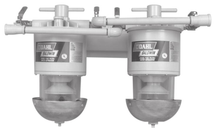
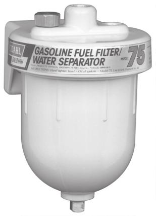
9 HOW THE DAHL SYSTEM WORKS MARINE Choose the size which can accommodate the flow rate recommended in the chart. (Maximum flow rate listed is for convenience in comparing with other systems only.) For most efficient separation and filtration, select from the recommended column. Flow Rates in Gallons Per Hour The chart is for Filter/Water Separators. Recyclers and Recycler/Blenders are limited by the pump. For example, a single 00 recycler unit has a flow rate limited to 0 GPH (U.S.), and a double 00 recycler unit has a flow rate limited to 0 GPH (U.S.).. The contaminated fuel enters the inlet port.. The T-Bolt redirects the fuel downward through the centerpipe.. Fuel flows through the reverse flow valve.. Fuel flow is spread by the depressurizer cone.. As fuel is discharged from the depressurizer cone, 0% of contaminant separation takes place. Most of the solid particles and water settle into the quiet zone of the bowl.. As the fuel rises upward, any remaining minute water droplets coalesce on the cone, baffle and bowl surfaces. Droplet size and weight gradually increase, causing downward flow into the sump.. Fuel is filtered completely by the element, which contains HydroShield media. The clean fuel then continues upward through the outlet port and on to the pump and injection system. HOW TO SELECT THE RIGHT DAHL FILTER FLOW RATES GPH (U.S.) Model Series Recommended Maximum Sump Capacity 0 0 oz oz. 00 Double 0 0 oz oz. 0 Double 0 00 oz oz. 00 Double 0 00 oz oz. 00 Double 0 0 oz. All Multiple Multiply Flow Rate and Sump Capacity Units by Number of Units ACCESSORIES REPLACEMENT FOR SERIES INDICATED: Series Shock Pad Mounting Kit...-SK... -SK... -SK...-SK REPLACEMENT GASKET FOR SERIES INDICATED: Series Gasket Kits ( rebuild)...00-gk...0-gk GK...00-GK REPLACEMENT ELEMENT FOR SERIES INDICATED: Series Micron Element Micron Element...-W...0-W... -W... 0-W...0-W 0 Micron Element WARNING: DO NOT use gasoline or any form of alcohol or anything containing it inside or outside a DAHL Fuel/Water Separator, with the exception of the DAHL Model which is designed to allow use on Gasoline Engines.
10 Dahl Fuel/Water Separators WHY DAHL? Filters are a compromise wherever located. As a one-step strainer, a filter must be porous enough to allow sufficient flow volume. This means the filters which came with the equipment are usually in the 0-0 micron range. However, if a more efficient media were used, the filter would become clogged very quickly, restricting the flow and resulting in frequent, costly element changes. Not only that, many fuel filters are not designed to remove significant amounts of water, even though water is a primary cause of injector pump and nozzle damage. Water and solid contaminants displace the diesel fuels lubricative coating on precision injection components. The loss of this protection results in wear, erosion, surface pitting and eventual fuel pressure loss. THE SOLUTION DAHL s functional dual chamber, -stage diesel fuel filter/water separators provide efficient suction side water separation and contaminant filtration. The key is the unique DAHL patented depressurizer cone, which spreads the flow of the fuel. The fact is, the more area to flow over, the slower the flow and the greater the separation of water and dirt from the fuel. DAHL diesel fuel filter/ water separators have less mechanical flow resistance because the fuel changes direction only once. COMPLETE EFFICIENCY DAHL removes virtually 00% of the water and solid contaminants. PROVEN PERFORMANCE DAHL diesel fuel/water separators have been tested and proven over millions of miles and hours under all sorts of conditions. Ask anyone who has used DAHL, or any Baldwin user, as Baldwin Filters makes DAHL products. MARINE DURABILITY Marine units, 00-M, 0-M, 00-M, 00-MMV, 00-M and 00-MMV have passed severe U.L. testing. Tests include fire endurance, vibration fatigue, impact and thermal shock. These filters have also met U.S. Coast Guard requirements for Marine Applications. CLEAN FUEL DAHL eliminates nearly all of the engine problems caused by water and solid contaminants in diesel fuel. addition to saving you the cost of expensive repair bills and aggravation, you can expect: Longer jection System Component Life Full Power Performance Less Element Replacement Cost BALDWIN LIMITED WARRANTY Baldwin Filters warrants each new Baldwin or DAHL Filter Product to be free from defects in workmanship and material as follows:. Housings one year from date of user s purchase.. Electronics, Pumps and Motors 0 days from date of user s purchase.. Replaceable Elements, Spin-ons, Etc. during equipment manufacturer s recommended filter service interval, if properly installed in a Baldwin recommended application. Baldwin will replace or repair at its option, free of charge, any part still in the Baldwin warranty period found by Baldwin s inspection to be defective when such product is returned to place of purchase or to Baldwin Filters with transportation charges prepaid. Specifically excluded from this warranty is damage resulting from excessive force, negligence, abuse, misuse, misapplication, tampering, improper installation, fire or accident. The warranty will not apply to any filter which has been cut apart or subject to tampering. Also, damage to plastic parts of fuel/water separators caused by the use of fluids containing alcohol is not covered by this warranty. Full details of this warranty are in the Policy and Procedures Manual at the Baldwin or DAHL distributor or may be obtained from Baldwin s Service Engineering Department. SUPERIOR ENGINEERING Die cast aluminum Impact-resistant large transparent or aluminium bowl Element service life is several times longer than conventional Easy to install, service and clean Positive air elimination Advanced spring design assures positive element seal Less mechanical resistance because of streamlined flow path Baffle system is designed to stop emulsification and disperse trapped air Ball check valve to stop reverse flow Six series specifically designed to fit diesel engines of various capacities Authorized Dealer Baldwin Filters Kearney NE -00 (00) baldwinfilter.com Designed and manufactured in the USA. Form (R /) 0 Baldwin Filters, a Parker Hannifin Company
200 & 300 SERIES Diesel Fuel/Water Separators
 200 & 300 SERIES Diesel Fuel/Water Separators Installation Operation Parts Service Information INSTALLATION A. FILTER MOUNTED ABOVE FUEL STORAGE TANK 1. Select a location in the fuel line between the fuel
RECYCLER, RECYCLER/BLENDER & FUEL TRANSFER MODELS
 RECYCLER, RECYCLER/BLENDER & FUEL TRANSFER MODELS Installation Operation Parts Service Information DAHL Recycler Units efficiently separate water and solid contaminants to maintain stability and purity
DIESEL FUEL FILTER/WATER SEPARATORS & Recycler Systems
 DIESEL FUEL FILTER/WATER SEPARATORS & Recycler Systems DAHL DIESEL FUEL FILTER/WATER SEPARATORS REMOVE DIESEL FUEL SYSTEM PROBLEMS ALONG WITH WATER Water and solid contaminants displace the diesel fuel
Model 100 Series Kits
 Introductory Installation Information 1. Always install DAHL 100 on the vacuum (suction) side of transfer pump and ahead of any other filter: On domestic vehicles, remove the 3/8 inch I.D. hose from the
Marine Fuel Filtration. Marine Turbine Series. Stage One: Separation. Stage Two: Coalescing. Stage Three: Filtration. And more
 filter assemblies are designed to be installed on the vacuum side of the fuel transfer pump for best efficiency and protect precision engine components from dirt, rust, algae, asphaltines, varnishes, and
75500MAX Series and 75500MAXM Series
 75500MAX Series and 75500MAXM Series Marine Fuel Filter/Water Separators Instruction Part Number 15349 Rev E Racor Turbine Series fuel filter/ water separators protect the precision components of your
All Racor filter materials and seals are compatible with ultra-low sulphur diesel (ULSD) fuel and B2 to B20 Biodiesel. See Racor bulletin 7679.
 fuel and B2 to B20 Biodiesel. See Racor bulletin 7679.") 000MA Water-in-fuel sensor and indicator. MA units have shielded see-thru bowls; MAM bowls are all-metal. UL-listed drain valve and water sensor probe options are available. Turbine Series Electric Primer
000MA Water-in-fuel sensor and indicator. MA units have shielded see-thru bowls; MAM bowls are all-metal. UL-listed drain valve and water sensor probe options are available. Turbine Series Electric Primer
DIESEL FUEL FILTER/WATER SEPARATORS & Re c ycler/blender Syste m s
 DIESEL FUEL FILTER/WATER SEPARATORS & Re c ycler/blender Syste m s DAHL DIESEL FUEL FILTER/WATER SEPARATORS REMOVE DIESEL FUEL SYSTEM PROBLEMS ALONG WITH WATER Water and solid contaminants displace the
660R-RAC Series. Gasoline Fuel Filter/Water Separators. Overview: Contact Information: Product Features: Instruction Part Number Rev F
 660R-RAC Series Gasoline Fuel Filter/Water Separators Instruction Part Number 1385 Rev F Overview: Don t be caught in the water without one of these Racor gasoline spin on series filters. These filters
120RMAM Marine Series Fuel Filter/Water Separators
 10RMAM Marine Series Fuel Filter/Water Separators Instruction Part Number 1945 Rev A Overview The 10RMAM fuel filter/water separator features 1/4-18 NPTF inlet and outlet fuel ports and a unitized mounting
320R-RAC Series. Gasoline Fuel Filter/Water Separators. Overview: Contact Information: Product Features: Instruction Part Number Rev.
 30R-RAC Series Gasoline Fuel Filter/Water Separators Instruction Part Number 37 Rev. D Overview: Racor 30R-RAC series filters are designed for high-performance applications, which means your engine will
Marine Fuel Filtration Marine 800 Series
 Racor recyclers offer large diesel engine operators both ease of maintenance and continuous engine operation. Continuous operations include filter changeouts and the draining of accumulated water from
Product Features: Removes 99% of free water. Available with 2, 10, or 30 micron Aquabloc II media
 120A and 120B Series Fuel Filter/Water Separators Instruction Part Number 10219 Rev B Overview: 120A and 120B fuel filter/water separators are designed to be installed on the suction side of the fuel system
Marine Turbine Series
 1000MA Water-in-fuel sensor and indicator. All Racor filter materials and seals are compatible with ultra-low sulphur diesel (ULSD) fuel and B2 to B20 Biodiesel. See Racor bulletin 7679. The complete Primer
Racor 75500FGX Turbine Series fuel
 Installation Instructions 75500FGX Fuel Filter Racor 75500FGX Turbine Series fuel filter/water separator assemblies are designed to be installed on the vacuum side of the fuel transfer pump for best efficiency
400 Series Spin-on Fuel Filter/Water Separators
 00 Series Spin-on Fuel Filter/Water Separators Instruction Part Number 09 Rev G 00 Series fuel filter/water separators are designed to handle today s tough fuel filtration problems and can be used anywhere
Introduction. Marine Turbine Series. Model Illustrations. Special Notes. Specifications 77/1000MA 73/1000MA 75/500MAX 75/900MAX 79/1000MAV 75/1000MAX
 Introduction Model Illustrations 5MA 5MAM 9MA 1MA 7/1MA 77/1MA 75/5MAX Special Notes 75/9MAX 75/1MAX 79/1MAV 1. See--thru bowl MA / MAX / MAV units are approved for Diesel service only. UL Listed, USCG
900MA/MAM and 1000MA/MAM (for marine applications)
") 900MA/MAM and 1000MA/MAM (for marine applications) Fuel Filter/Water Separator Instruction Part Number 19526 Rev B Racor Turbine Series fuel filter/ water separator protects the precision components of
900MA/MAM and 1000MA/MAM (for marine applications) Fuel Filter/Water Separator Instruction Part Number 19526 Rev B Racor Turbine Series fuel filter/ water separator protects the precision components of
Marine Fuel Filtration. Marine FBO. Features:
 The Racor assembly is specifically designed to meet the filtration requirements of today s high pressure common rail diesel injection systems. The unit is used for fuel dispensing pumps or as a primary
Maintenance Manual. Automated Fuel Maintenance System FTI-5A SINGLE TANK FUEL TECHNOLOGIES INTERNATIONAL
 Maintenance Manual Automated Fuel Maintenance System FTI-5A SINGLE TANK FUEL TECHNOLOGIES INTERNATIONAL 05/01/2016 Rev A Fuel Technologies FTI-5A Single Tank Maintenance Section FTI - Fuel Maintenance
General The Racor Marine Diesel Spin--on Series feature a variety of compact sizes to fit most installations and cramped engine compartments.
 Selection Selection Information General The Racor Marine Diesel Spin--on Series feature a variety of compact sizes to fit most installations and cramped engine compartments. Mounting Heads: These units
Air Operated Grease Ratio Pumps 50:1 BGRP
 INSTRUCTION MANUAL S1350, Rev C Air Operated Grease Ratio Pumps 50:1 BGRP Congratulations on purchase of this World Class Air Operated Grease Ratio Pump! World-class Industrial High Pressure Grease pump
Maintenance Manual. Automated. Fuel Maintenance System FTI-5A. FUEL TECHNOLOGIES INTERNATIONAL LLC
 Maintenance Manual Automated Fuel Maintenance System FTI-5A FUEL TECHNOLOGIES INTERNATIONAL LLC www.fueltechnologiesinternational.com 03/01/2011 - Fuel Technologies FTI-5A Maintenance Section FTI - Fuel
Maintenance Manual WITH ONE SUBMERSIBLE PUMP. Automated Fuel Maintenance System FTI-5A FUEL TECHNOLOGIES INTERNATIONAL LLC
 Maintenance Manual WITH ONE SUBMERSIBLE PUMP Automated Fuel Maintenance System FTI-5A FUEL TECHNOLOGIES INTERNATIONAL LLC Replacement Manuals Available on Website: www.fueltechnologiesinternational.com
Product Features. Easy installation. Pump adds only 3.3 to the overall assembly height. 60 GPH (227 LPH) flow rate while in priming mode.
 flow rate while in priming mode.") Primer Pump Kits RKP1912 (12 vdc) and RKP1924 (24 vdc) Instruction Part Number 14356 Rev C Primer pump kits are an innovative and proprietary system consisting of a prescreen filter, a flow by-pass circuit,
Primer Pump Kits RKP1912 (12 vdc) and RKP1924 (24 vdc) Instruction Part Number 14356 Rev C Primer pump kits are an innovative and proprietary system consisting of a prescreen filter, a flow by-pass circuit,
SERVICE PARTS LIST SPECIFY CATALOG NO. AND SERIAL NO. WHEN ORDERING PARTS 13 HP DIRECT DRIVE PRESSURE WASHER CATALOG NO
 SPECIFY CATALOG NO. AND SERIAL NO. WHEN ORDERING PARTS HP DIRECT DRIVE PRESSURE WASHER CATALOG NO. 555-22 SERVICE PARTS LIST STARTING SERIAL NUMBER B06A REVISED BULLETIN PAGE OF BULLETIN NO. 5-20-000 DATE
INSTRUCTION AND MAINTENANCE MANUAL GFH45 PRESSURE REGULATOR
 Enidine / Conoflow 105 Commerce Way Westminster, SC 29693 Tel: (864) 647-9521 Fax: (864) 647-7993 WARNING Conoflow s products are designed and manufactured using materials and workmanship required to meet
BMK-18 U.S. Patent #5,298,158
 BMK- U.S. Patent #5,29,5 Marine Dual Remote Filtration System Mounting Kit Installation and Servicing Instructions IMPORTANT NOTICE Read all instructions completely before attempting to install this unit.
Sachs shock manual. ( ) 2 & 4 Stroke RR Enduro. ( ) RS Dual Sport
 2 & 4 Stroke RR Enduro. ( ) RS Dual Sport") Sachs shock manual (2013 2015) 2 & 4 Stroke RR Enduro (2014-2015) RS Dual Sport 1 Introduction The procedures in this manual must take place in a clean environment using professional tools and some specific,
Sachs shock manual (2013 2015) 2 & 4 Stroke RR Enduro (2014-2015) RS Dual Sport 1 Introduction The procedures in this manual must take place in a clean environment using professional tools and some specific,
EJECTORS GENERAL OPERATION & MAINTENANCE MANUAL
 EJECTORS GENERAL OPERATION & MAINTENANCE MANUAL The information contained in this manual was current at the time of printing. The most current versions of all Hydro Instruments manuals can be found on
IMPORTANT OPERATING CONDITIONS. Failure to comply with any of these conditions invalidates the warranty. STANDARD CONFIGURATIONS
 X-SERIES TRIPLEX CERAMIC PLUNGER PUMPS OPERATING MANUAL MODELS X8 X10 X20 IMPORTANT OPERATING CONDITIONS Failure to comply with any of these conditions invalidates the warranty. Lubrication - Prior to
FPS- 80. Manual. Reverso Pumps, Inc. Ph: (954)
") FPS- 80 Manual Table of Contents System Overview... 1 Control Panel Overview... 2 Technical Specifications... 3 Electrical and Installation... Tank Diagrams... 5 Initial Setup... 6 Digital Timer Instructions:
FPS- 80 Manual Table of Contents System Overview... 1 Control Panel Overview... 2 Technical Specifications... 3 Electrical and Installation... Tank Diagrams... 5 Initial Setup... 6 Digital Timer Instructions:
Air Operated 1:1 Oil Ratio Pump OP-11
 INSTRUCTION MANUAL Air Operated 1:1 Oil Ratio Pump OP-11 Congratulations on purchase of this World Class Air Operated Oil Ratio Pump! S1221, Rev C World-class Industrial Oil Dispensing pumps with guaranteed
BMK-30. Heavy-Duty By-Pass Filtration System Installation and Servicing Instructions
 BMK-30 Heavy-Duty By-Pass Filtration System Installation and Servicing Instructions IMPORTANT NOTICE Read all instructions completely before attempting to install this unit. Improper installation could
INSTRUCTION AND MAINTENANCE MANUAL FR95 PRESSURE REGULATOR
 Enidine / Conoflow 105 Commerce Way Westminster, SC 29693 Tel: (864) 647-9521 Fax: (864) 647-7993 WARNING Conoflow s products are designed and manufactured using materials and workmanship required to meet
OWNERS MANUAL INSTALLATION AND OPERATING INSTRUCTIONS REPAIR PARTS LIST. Centrifugal Pump Primer MODEL 6D, HAN-DEE PRIMER
 OWNERS MANUAL INSTALLATION AND OPERATING INSTRUCTIONS REPAIR PARTS LIST Centrifugal Pump Primer 383 0893 MODEL 6D, HAN-DEE PRIMER IMPORTANT For best possible performance continuous, satisfactory operation,
INSTRUCTIONS AND SERVICE MANUAL WITH PARTS LIST
 CMP SERIES CPM15-15B (25905F300) CPM15-15B-H/D (25905F301) CPM18-15B (25905F303) CPM18-15B-H/D (25905F304) INDUSTRIAL PUMPS INSTRUCTIONS AND SERVICE MANUAL WITH PARTS LIST NOTE! To the installer: Please
PRESSURE REGULATOR BACK PRESSURE TO ATMOSPHERE WITH OUTSIDE SUPPLY
 PRESSURE REGULATOR BACK PRESSURE TO ATMOSPHERE WITH OUTSIDE SUPPLY All Rights Reserved. All contents of this publication including illustrations are believed to be reliable. And while efforts have been
Dual Remote Filtration System Installation and Servicing Instructions
 IMPORTANT NOTICE Read all instructions completely before attempting to install this unit. Improper installation could result in serious system and/or equipment damage. The installation of this system is
HALLMARK INDUSTRIES INC
 Performance Part No. HP. CONVERTIBLE JET PUMP USER S MANUAL GPH of Water @ Total Discharge Pressure of 40 psi Max. Pressure Max suction (shallow well) Max Suction (deep well) Max GPM (@0 head) Max Discharge
WARCO CHEMAG SERIES GH FILTERS
 WARCO CHEMAG SERIES GH FILTERS High Performance Pleated & Bag Type Filtration Systems INSTALLATION, OPERATION, AND MAINTENANCE INSTRUCTIONS Thank you for your purchase of a WARCO Series GH Filtration System.
Emergency Shear Valves
 Emergency Shear Valves 0060 Underpump Emergency Valve The Emco Wheaton 0060 Emergency Shear Valve incorporates a replaceable shear section and a heat sensitive fusible link assembly. The valve can be manually
Port size: 1 NPT Shaft size: 5/8 Solid or 1/2 Hollow. Pump shaft rotation: CW Standard/CCW Optional. Weight: 19 lbs. Rollers: Ultra Rollers standard
 4-, 5-, 6-, 7-, 8-Roller Pump Instruction Manual 01509-MN (Read carefully before installation and operation) GENERAL Delavan roller pumps are available with a variety of options, such as a choice of roller
QuickServe Online ( ) ISB6.7 CM2350 B101 Service Manual
 ISB6.7 CM2350 B101 Service Manual") Page 1 of 31 (/qs3/pubsys2/xml/en/manual/2883567/2883567-titlepage.html) Select Service Tools Recommended Cummins Service Tools 0.043 inch orificed diagnostic fuel line, Part Number 3164621 Diagnostic
Page 1 of 31 (/qs3/pubsys2/xml/en/manual/2883567/2883567-titlepage.html) Select Service Tools Recommended Cummins Service Tools 0.043 inch orificed diagnostic fuel line, Part Number 3164621 Diagnostic
Spin Klin 3"-4" Apollo Angle
 Spin Klin 3"-4" Apollo Angle w w w. a r k a l - f i l t e r s. c o m 3"-4" Spin Klin Angle Apollo Battery Service & Maintenance Manual Table of Contents Subject Page No. 1. Introduction... 3 2. Safety
#9040 FUEL TANK SWEEPER
 #9040 FUEL TANK SWEEPER INSTRUCTION MANUAL FILTERS AND REMOVES FINE BIO-CONTAMINANTS, ALGAE, ETC. SWEEPING PROCESS REMOVES LARGE CONTAMINANTS FROM OIL TANKS SUCH AS RUST, WATER, CRUDE AND DIRT CIRCULATES
Page 1 of 19. Part# /10/2006
 Part# 1002733-01 10/10/2006 This manual contains important information concerning the installation and operation of the gun washers listed above. Read manual thoroughly and keep for future reference INSTRUCTIONS
EVAC Commercial Marine Equipment TOILET TECHNICAL DATA EVAC 90, STAINLESS STEEL, FLOOR MODEL, *SHOCK TESTED. Fresh water.
 16 Apr 2009 Doc. 1:141J TECHNICAL DATA 5327002 EVAC 90, STAINLESS STEEL, FLOOR MODEL, *SHOCK TESTED Fresh water connection Shut-off valve Strainer Vacuum breaker 390 Gasket Seat and cover Pneumatic push
Val-Matic Air / Oil Hydraulic Panel Pump Control System. Operation, Maintenance and Installation Manual
 Manual No. 5AOP-OM1-2 Val-Matic Air / Oil Hydraulic Panel Pump Control System Operation, Maintenance and Installation Manual INTRODUCTION... 1 RECEIVING AND STORAGE... 1 DESCRIPTION OF OPERATION... 1 INSTALLATION...
Electric Diesel Pump EDP/12, EDP/24
 INSTRUCTION MANUAL Electric Diesel Pump EDP/1, EDP/4 S1940, Rev C Congratulations on purchase of this World Class Electric Diesel Pump! Portable Diesel transfer pumps designed for everyday use in Agricultural,
Hydraulic PTO Flow Device
 Safety, Operation, and Maintenance Manual WARNING Improper use of this tool can result in serious bodily injury This manual contains important information about product function and safety. Please read
300 Series INSTRUCTION MANUAL. Compressed Air Filters Models 302 (grade) through 317 (grade)
 through 317 (grade)") INSTRUCTION MANUAL 300 Series Compressed Air Filters Models 302 (grade) through 317 (grade) FORM NO.: 3259480 REVISION: 01/2014 READ AND UNDERSTAND THIS MANUAL PRIOR TO OPERATING OR SERVICING THIS PRODUCT.
INSTRUCTION MANUAL 300 Series Compressed Air Filters Models 302 (grade) through 317 (grade) FORM NO.: 3259480 REVISION: 01/2014 READ AND UNDERSTAND THIS MANUAL PRIOR TO OPERATING OR SERVICING THIS PRODUCT.
GROUP 13C 13C-1 CONTENTS GENERAL DESCRIPTION... 13C-2 FUEL TANK... 13C-11 FUEL SUPPLY DIAGNOSIS... 13C-3 SPECIAL TOOLS... 13C-8
 13C-1 GROUP 13C CONTENTS GENERAL DESCRIPTION......... 13C-2 DIAGNOSIS....... 13C-3 INTRODUCTION TO DIAGNOSIS........................ 13C-3 TROUBOLESHOOTING STRATEGY..... 13C-3 SYMPTOM CHART...................
FPS-500. Fuel Polishing System Eliminates Microbial Contamination. Operating Manual
 FPS-500 Fuel Polishing System Eliminates Microbial Contamination Operating Manual Stabilizes Fuel Removes Water & Sludge Prevents Tank Sediments Improves Engine Reliability Optimizes Fuel Quality Optimal
INSTALLATION, OPERATION, AND MAINTENANCE MANUAL
 INSTALLATION, OPERATION, AND MAINTENANCE MANUAL MODEL 4D-200 REDUCED PRESSURE PRINCIPLE (RPZ) & MODEL 4D-700 REDUCED PRESSURE DETECTOR ASSEMBLY (RPDA) BACKFLOW PREVENTERS 2 ½ 10 Conbraco Industries Inc.
SERVICING INSTRUCTIONS
 TSP Series 66 Triplex Plunger Pump SERVICING INSTRUCTIONS TRIPLEX TRIPLEX SERVICING PUMP PROCEDURES Valve Replacement: All inlet and discharge valves can be serviced without disrupting the inlet or discharge
Operating Manual. High Performance Vacuum Pump Models and 15600
 Operating Manual High Performance Vacuum Pump Models 15400 and 15600 CoolTech High Performance Vacuum Pumps Congratulations on purchasing one of Robinair s top quality CoolTech vacuum pumps. Your pump
TYPE E Main Valve Sizes 3 /8 through 12
 Technical Data SD 3001E PRINTED IN U.S.A. SD 3001E/9709 SPENCE ENGINEERING COMPANY, INC. 150 COLDENHAM ROAD, WALDEN, NY 12586-2035 A B TYPE E MAIN VALVE FACE TO FACE DIMENSIONS C D E DIMENSIONS (inches)
Crispin Valves Operating Guide. Crispin
 Crispin Valves Operating Guide Crispin Since 1905 Crispin Multiplex Manufacturing Co. 600 Fowler Avenue Berwick, PA 18603 1-800-AIR-VALV T: (570) 752-4524 F: (570) 752-4962 www.crispinvalve.com sales@crispinvalve.com
OWNER S MANUAL. Model GALLON SPRAYER REVISION 11/11
 OWNER S MANUAL Model 675 100 GALLON SPRAYER 010-0675 REVISION 11/11 TABLE OF CONTENTS PAGE INSTALLATION INSTRUCTIONS FOR JOHN DEERE 6000 SERIES 3 INSTALLATION OF FENDER SUPPORT 3 INSTALLATION OF TANK AND
CONTENTS. VIKING PUMP, INC. A Unit of IDEX Corporation Cedar Falls, IA USA SECTION TSM 710.1
 TECHNICAL SERVICE MANUAL industrial heavy duty motor speed pumps SERIES 4076 AND 4176 SIZES hle, ate and ale SECTION TSM 710.1 PAGE 1 of 8 ISSUE B CONTENTS Introduction....................... 1 Safety
LABORATORY ZERO AIR GENERATOR MODEL N-GC1500 USER S MANUAL
 LABORATORY ZERO AIR GENERATOR MODEL N-GC1500 USER S MANUAL Content 1. Introduction...2 2. Important safety instruction...3 3. System component...4 4. Engineering design overview...5 5. Installation...6
Maintenance Information
 16573347 Edition 2 February 2014 Air Grinder Series 88H Maintenance Information Save These Instructions Product Safety Information WARNING Failure to observe the following warnings, and to avoid these
4" Spin Klin Twin Apollo Battery. Service & Maintenance Manual
 4" Spin Klin Twin Apollo Battery Service & Maintenance Manual Table of Contents Subject Page No. 1. Introduction... 3 2. Safety Instructions... 3 3. Description and Operation... 4 4. Technical Data...
Spin Klin 4" Apollo Twin
 Spin Klin 4" Apollo Twin w w w. a r k a l - f i l t e r s. c o m 4" Spin Klin Twin Apollo Battery Service & Maintenance Manual Table of Contents Subject Page No. 1. Introduction... 3 2. Safety Instructions...
Fixed Displacement Gear Pumps
 Fixed Displacement Gear Pumps D/H/HD Series Introduction Series D/H/HD Features Pressure-loaded design Efficient, simple design - few moving parts Exceptionally compact and lightweight for their capacity
High Performance Vacuum Pump Model 15120A/15121A Operating Manual...
 High Performance Vacuum Pump Model 15120A/15121A Operating Manual... Operating Manual Table of Contents Warnings...1 CoolTech high performance vacuum pumps...1 Pump components...2 Before using your vacuum
INSTALLATION INSTRUCTIONS FOR THE TRUCK MOUNTED VIPER ADDITIVE INJECTION SYSTEM GTP-8776C
 INSTALLATION INSTRUCTIONS FOR THE TRUCK MOUNTED VIPER ADDITIVE INJECTION SYSTEM GTP-8776C This additive injection system was designed to be used with five gallon jug of additive. The system is supplied
Industrial Pro FH239 Series Filter/Separator/Warmer Installation Instructions
 Industrial Pro FH239 Series Filter/Separator/Warmer Installation Instructions K L Cover Industrial Pro Single Short H I W A B D F P C E J Bottom Bowl G Vent Cap Filter Element (includes part C) I R S T
Hydraulic Immediate Need Power Pack
 Safety, Operation, and Maintenance Manual WARNING Improper use of this tool can result in serious bodily injury This manual contains important information about product function and safety. Please read
OWNER S TECHNICAL MANUAL
 OWNER S TECHNICAL MANUAL 2.5kg Grease Kit 6336 Description The Champion 6336 2.5kg grease kit is a manually operated, spring powered grease kit that comes complete with a hand piece. It is designed to
MODEL HD-BTC. Installation, Operation & Repair Parts Information REV041416
 MODEL HD-BTC Installation, Operation & Repair Parts Information REV041416 TABLE OF CONTENTS SAFETY INSTRUCTIONS 1 DEFINITIONS 1 SPECIFICATIONS 2 INSTALLATION INSTRUCTIONS 2 OPERATING INSTRUCTIONS 2 MAINTENANCE
TECHNICAL DATA CAUTION
 Page 1 of 6 1. DESCRIPTION The Viking Model D-2 Accelerator is a quick-opening device, with an integral anti-flood assembly, used to increase the operating speed of a differential type dry pipe valve.
BMK-12. Dual-Gard By-Pass Filter Mounting Kit Installation and Servicing Instructions
 BMK-12 Dual-Gard By-Pass Filter Mounting Kit Installation and Servicing Instructions IMPORTANT NOTICE Read all instructions completely before attempting to install this unit. Improper installation could
AIR/HYDRAULIC INJECTION GUN MODEL INSTRUCTIONS
 I. OPERATION & DESCRIPTION The Air / Hydraulic Injection Gun is a high-pressure tool that should be used with caution and according to these instructions. IMPORTANT: The Gun is 0,000 psi rated. Do not
DISPLACEMENT PUMP INSTRUCTIONS-PARTS LIST Rev. K. Model , Series A Model , Series B Model , Series A
 INSTRUCTIONS-PARTS LIST INSTRUCTIONS This manual contains important warnings and information. READ AND KEEP FOR REFERENCE. DISPLACEMENT PUMP 308190 Rev. K 3000 psi (210 bar) MAXIMUM WORKING PRESSURE Model
Section 10 Chapter 17
 Section 10 Chapter 17 24 Valve, 8.3 Liter Engine Air Intake System Note: All coding used in the 8.3 Liter and 9 Liter engine manuals are Cummins engine codes. These engine codes have no meaning to New
Maintenance Information
 16573370 Edition 2 February 2014 Air Grinder 99V Series Maintenance Information Save These Instructions Product Safety Information WARNING Failure to observe the following warnings, and to avoid these
MicroCoat System Operating Manual MC4000 Series MC785M, MC785M-WF Spray Valves
 MicroCoat System Operating Manual MC Series MC785M, MC785M-WF Spray Valves A NORDSON COMPANY Introduction The MicroCoat System provides precise lubrication control for metal stamping operations. The MC
Ideal Installation. I & M Mark 67 (1/2 6 ) Control Line. Installation & Maintenance Instructions for Mark 67 Pressure Regulators
 Control Line. Installation & Maintenance Instructions for Mark 67 Pressure Regulators") I & M Mark (/ ) 0 Wasson Road Cincinnati, OH 0 USA Phone --00 Fax -8-00 info@richardsind.com www.jordanvalve.com Installation & Maintenance Instructions for Mark Pressure Regulators Warning: Jordan Valve
I & M Mark (/ ) 0 Wasson Road Cincinnati, OH 0 USA Phone --00 Fax -8-00 info@richardsind.com www.jordanvalve.com Installation & Maintenance Instructions for Mark Pressure Regulators Warning: Jordan Valve
1/2" AIR DRIVEN DIAPHRAGM PUMP
 1/2" DRIVEN DIAPHRAGM PUMP OPERATION AND SERVICE GUIDE O-1225D NOV. 2008 Page 1 of 6 Refer to Bulletin P-605, Parts List P-9151 DRIVEN, DOUBLE DIAPHRAGM PUMP MANUAL Congratulations on purchasing one of
Airless Spray Gun INSTRUCTIONS DP psi (345 bar) Maximum Working Pressure
 Maximum Working Pressure") INSTRUCTIONS DP-6376 Airless Spray Gun 5000 psi (345 bar) Maximum Working Pressure INSTRUCTIONS This manual contains important warnings and information. READ AND KEEP FOR REFERENCE. Table of Contents Warnings......................................
INSTRUCTIONS DP-6376 Airless Spray Gun 5000 psi (345 bar) Maximum Working Pressure INSTRUCTIONS This manual contains important warnings and information. READ AND KEEP FOR REFERENCE. Table of Contents Warnings......................................
MicroCoat. System Operating Manual MC2000 Series. MC785, MC785-WF Spray Valves. US: UK: Mexico:
 MicroCoat System Operating Manual MC2 Series MC785, MC785-WF Spray Valves A NORDSON COMPANY US: 8-498-8865 UK: 8 585733 Mexico: 1-8-556-3484 Introduction The MicroCoat System provides precise lubrication
MODEL NUMBER: MEDIUM DUTY ONBOARD AIR SYSTEM
 MODEL NUMBER: 10003 MEDIUM DUTY ONBOARD AIR SYSTEM IMPORTANT: It is essential that you and any other operator of this product read and understand the contents of this manual before installing and using
HYDRAULIC PUMP. INSTALLATION, OPERATION, & MAINTENANCE MANUAL MAINTENANCE MANUAL #: MM-HP Rev. A Page 1 of 12
 INSTALLATION, OPERATION, & #: MM-HP001 4-20-09 Rev. A Page 1 of 12 HYDRAULIC PUMP PART NUMBER HP46982ALSL & HP46982SL HYDRAULIC PUMP MM-HP001 Rev. A Page 2 of 12 Table of Contents 1.0 General Page 3 2.0
Maintenance Information
 16572679 Edition 2 May 2014 Air Drill QP Series Maintenance Information Save These Instructions Product Safety Information WARNING Failure to observe the following warnings, and to avoid these potentially
SECTION 4 - FUEL/LUBRICATION/COOLING
 For Arctic Cat Discount Parts Call 606-678-9623 or 606-561-4983 SECTION 4 - FUEL/LUBRICATION/COOLING 4 TABLE OF CONTENTS Carburetor Specifications... 4-2 Carburetor Schematic... 4-2 Carburetor... 4-3 Cleaning
MK Rittenhouse & Sons Ltd. 115 Litre/30 US Gallon Greenhouse Sprayer Manual
 MK Rittenhouse & Sons Ltd. 115 Litre/30 US Gallon Greenhouse Sprayer Manual TABLE OF CONTENTS Introduction 3 Precautions & Maintenance 4-5 Piston pump Care & Maintenance 5-6 Shut Down & Winterizing 6 Troubleshooting
Combustion Technologies By-Pass Filtration Instructions
 Combustion Technologies By-Pass Filtration Instructions www.combustionusa.com Made in the USA Date Revision Jan 17 th, 2013 PLEASE READ AND UNDERSTAND ALL INSTALLATION INSTRUCTIONS PRIOR TO BEGINNING THE
12. CARBURETOR/FUEL PUMP
 12 CARBURETOR/FUEL PUMP SERVICE INFORMATION... 12-2 TROUBLESHOOTING... 12-2 THROTTLE VALVE DISASSEMBLY... 12-3 THROTTLE VALVE INSTALLATION... 12-4 CARBURETOR REMOVAL... 12-5 AUTO BYSTARTER... 12-6 FLOAT
Low Pressure Transfer Systems
 Chapter 7b Low Pressure Transfer Systems Automotive Diesel Technology Understanding & Servicing Contemporary Clean Diesel Technology Gus Wright Low Pressure Transfer Layout of a low-pressure fuel transfer
ESE Series Cast Iron Sewage Pumps
 Owner s Manual ESE Series Cast Iron Sewage Pumps TABLE OF CONTENTS General Safety.................... 2 Specifications..................... 3 Installation.................... 4 & 5 Troubleshooting...................
OPERATION MANUAL NT50 NOMAD TRANS-FLO AIR-OPERATED DOUBLE DIAPHRAGM PUMPS. A JDA Global Company. 7/11 rev. 1
 OPERATION MANUAL NT50 NOMAD TRANS-FLO AIR-OPERATED DOUBLE DIAPHRAGM PUMPS A JDA Global Company 7/11 rev. 1 CAUTION SAFETY POINTS TEMPERATURE LIMITS: Neoprene -17.8 C to 93.3 C 0 F to 200 F Buna-N -12.2
Kit Part Number:
 Equipped with AEM DRYFLOW Filter No oil required! Kit Part Number: 21-8203 2003-2005 Dodge Ram 5.7L V8 CARB EO # D-392-28 2005 Dodge Powerwagon Hemi CARB EO # D-392-28 Brute Force Intake Systems that are
INSTALLATION, OPERATION AND MAINTENANCE MANUAL (IOM)
") INSTALLATION, OPERATION AND MAINTENANCE MANUAL (IOM) IOM-1088 03-16 Model 1088 Vacu-Gard Blanketing Valve ISO Registered Company SECTION I I. DESCRIPTION AND SCOPE The Model 1088 Vacu-Gard is a tank blanketing
INSTALLATION, OPERATION AND MAINTENANCE MANUAL (IOM) IOM-1088 03-16 Model 1088 Vacu-Gard Blanketing Valve ISO Registered Company SECTION I I. DESCRIPTION AND SCOPE The Model 1088 Vacu-Gard is a tank blanketing
Air Operated Double Diaphragm Pump. M-Pump ½ Metallic Non Metallic Pump INSTALLATION, OPERATION & MAINTENANCE MANUAL
 Air Operated Double Diaphragm Pump M-Pump ½ Metallic Non Metallic Pump INSTALLATION, OPERATION & MAINTENANCE MANUAL 0.5 I.O.M rev 05. 12/2015 INDEX Title Section Introduction.1 Safety.2 Warranty, General
1-BUTTON DISPENSER INSTALLATION INSTRUCTIONS
 R 1-BUTTON DISPENSER INSTALLATION INSTRUCTIONS Model: #91162-00 The Green Earth II 1-button dispenser allows you to dispense one product for mop buckets and automatic scrubbers. The modular design lets
DEMA MODELS 606T INSTALLATION INSTRUCTIONS
 I. PARTS: A. Select-O-Spray Assembly B. 2 Pcs. Foot Strainers & 1/4" ID Tubing C. 4 Pcs. Mounting Screws & Anchors D. 1 Pc. 100-15K Metering Tip Kit TABLE 1 Hose I.D. 3/8" 1/2" 5/8" Max. Length 15 ft.
I-317. AWWA Check Valves WARNING INSTALLATION AND MAINTENANCE INSTRUCTIONS SERIES 317 WARNING
 Read and understand all instructions before attempting to install, remove, adjust, or perform maintenance on any Victaulic piping products Wear safety glasses, hardhat, and foot protection. Failure to
Service Handbook. High-Pressure Washer Pump
 Pump 629 9/28/01 3:22 PM Page 1 Service Handbook High-Pressure Washer Pump 3.532-629.0 10.00 Pump 629 9/28/01 3:22 PM Page 2 Pump 629 9/28/01 3:22 PM Page 3 TROUBLESHOOTING OVERVIEW How to Use This Manual