Autodesk's VEX Robotics Curriculum. Unit 6: Gears, Chains, and Sprockets
|
|
|
- Warren Wells
- 5 years ago
- Views:
Transcription
1 Autodesk's VEX Robotics Curriculum Unit 6: Gears, Chains, and Sprockets 1
2 Overview In Unit 6: Gears, Chains, and Sprockets, you modify the VEX test stand from Unit 5: Speed, Power, Torque, and DC Motors to learn more key engineering concepts that involve the use of gears, chains, and sprockets, along with key corresponding concepts such as reduction and ratio. The concepts regarding gears, gear ratios, force, torque, and motor speed have countless real-world applications. STEM Connections presents a scenario involving the operation of a winch installed on a coast guard helicopter for sea rescue operations. After completing the Think Phase and Build Phase in Unit 5: Speed, Power, Torque, and DC Motors, you will see how those concepts come into play in the real world. Unit Objectives After completing Unit 6: Gears, Chains, and Sprockets, you will be able to: Identify whether a gear reduction causes a speed reduction or a speed increase, and calculate gear ratios. Create a spur gear and animate a gear assembly using Autodesk Inventor Professional See the relationship between gearing, speed, and power; and incorporate VEX gears into a design. Modify the gearing of a VEX gearbox and understand the effect of gear ratios on speed and torque. Prerequisites Related resources for Unit 6: Gears, Chains, and Sprockets are: Unit 1: Introduction to VEX and Robotics Unit 2: Introduction to Autodesk Inventor Unit 4: Microcontroller and Transmitter Overview Unit 5: Speed, Power, Torque, and DC Motors Key Terms and Definitions The following key terms are used in Unit 6: Gears, Chains, and Sprockets: 2 Term Definition Bevel Gear A kind of gear in which the two gears working together lie in different planes, and have their teeth cut at right angles to the surfaces of two cones whose apices coincide with the point where the axes of the wheels would meet. Chain A connected flexible series of links used for fastening or securing objects and pulling or supporting loads. Gear One of a set of toothed wheels that work together to alter the relation between the speed of a driving mechanism and the speed of the driven parts. Autodesk's VEX Robotics Unit 6: Gears, Chains, and Sprockets
3 Term Definition Gear Ratio The relationship between the number of teeth on two gears that are meshed or two sprockets connected with a common roller chain, or the circumferences of two pulleys connected with a drive belt. Gear Ratio Gear ratio in a gearbox or transmission: The ratio between the rates at which the last and first gears rotate. Gear Reduction Involves using gears/sprockets/pulleys of two different sizes to work together, usually slowing output speed and increasing torque. Desired gear reductions can be accomplished in one or multiple stages. Gear Teeth A gear is different from a pulley in that a gear is a round wheel which has teeth that mesh with other gear teeth, allowing force to be fully transferred without slippage. Sprocket Any of various toothlike projections arranged on a wheel rim to engage the links of a chain. Spur Gear Spur gears are the simplest, and probably most common, type of gear. Their general form is a cylinder or disk. The teeth project radially, and with these "straight-cut gears," the leading edges of the teeth are aligned parallel to the axis of rotation. These gears can only mesh correctly if they are fitted to parallel axles. Worm Gear A worm is a gear that resembles a screw. It is a type of helical gear, but its helix angle is usually somewhat large (that is, close to 90 degrees) and its body is usually fairly long in the axial direction; and it is these attributes that give it its screwlike qualities. A worm is usually meshed with an ordinary looking, disk-shaped gear, which is called the gear, the wheel, the worm gear, or the worm wheel. The prime feature of a worm-and-gear set is that it allows the attainment of a high gear ratio with few parts in a small space. Required Supplies and Software The following supplies and software are used in Unit 6: Gears, Chains, and Sprockets: Supplies Software VEX Classroom Lab Kit Autodesk Inventor Professional 2011 Notebook and pen One assembled VEX motor test stand from the Unit 5: Speed, Power, Torque, and DC Motors > Build Phase. Overview 3
4 Supplies Software An assembled the gear ratio test stand from the Unit 6: Gears, Chains, and Sprockets > Build Phase. Small storage container for loose parts Work surface 5 lb. weight A surface (for example, a table or desk) with an edge at least 24 above the ground One stopwatch VEX Parts The following VEX parts are used in Unit 6: Gears, Chains, and Sprockets > Build Phase: 4 Quantity Part Number Abbreviations 5 BEARING-FLAT BF 10 NUT-832-KEPS NK 10 SCREW S4 2 SHAFT-3000 SQ3 2 SHAFT-COLLAR COL 1 SPACER-THICK SP2 1 SPACER-THIN SP1 1 VEX-12-TOOTH-GEAR G12 1 VEX-84-TOOTH-GEAR G84 2 WASHER-DELRIN WP Autodesk's VEX Robotics Unit 6: Gears, Chains, and Sprockets
5 VEX Parts The following VEX parts are used in Unit 6: Gears, Chains, and Sprockets > Amaze Phase: Quantity Part Number Abbreviations 1 VEX-36-TOOTH-GEAR G36 1 VEX-60-TOOTH-GEAR G60 Academic Standards The following national standards are supported in Unit 6: Gears, Chains, and Sprockets. Phase Standard Think Science (NSES) Unifying Concepts and Processes: Form and Function Physical Science: Motion and Forces Science and Technology: Abilities of Technological Design Technology (ITEA) 5.8: The Attributes of Design Mathematics (NCTM) Connections: Recognize and apply mathematics in contexts outside of mathematics. Algebra: Analyze change in various contexts. Measurement: Understand measurable attributes of objects and the units, systems, and processes of measurement. Communication: Communicate mathematical thinking coherently and clearly to peers, teachers, and others. Overview 5
6 Phase Standard Create Science (NSES) Unifying Concepts and Processes: Form and Function Physical Science: Motions and Forces Science and Technology: Abilities of Technological Design Technology (ITEA) 5.8: The Attributes of Design 5.9: Engineering Design 6.12: Use and Maintain Technological Products and Systems Mathematics (NCTM) Numbers and Operations: Understand numbers, ways of representing numbers, relationships among numbers, and number systems. Algebra Standard: Understand patterns, relations, and functions. Geometry Standard: Use visualization, spatial reasoning, and geometric modeling to solve problems. Measurement Standard: Understand measurable attributes of objects and the units, systems, and processes of measurement. Build Science (NSES) Unifying Concepts and Processes: Form and Function Physical Science: Motion and Forces Science and Technology: Abilities of Technological Design Technology (ITEA) 5.8: The Attributes of Design 5.9: Engineering Design 6.11: Appy the Design Process Mathematics (NCTM) Connections: Recognize and apply mathematics in contexts outside of mathematics. Numbers and Operations: Compute fluently and make reasonable estimates. Algebra: Analyze change in various contexts. Geometry: Use visualization, spatial reasoning, and geometric modeling to solve problems. Measurement: Understand measurable attributes of objects and the units, systems, and processes of measurement. Apply appropriate techniques, tools, and formulas to determine measurements. 6 Autodesk's VEX Robotics Unit 6: Gears, Chains, and Sprockets
7 Phase Standard Amaze Science (NSES) Unifying Concepts and Processes: Form and Function Physical Science: Motion and Forces Science and Technology: Abilities of Technological Design Technology (ITEA) 5.8: The Attributes of Design Mathematics (NCTM) Connections: Recognize and apply mathematics in contexts outside of mathematics. Numbers and Operations: Compute fluently and make reasonable estimates. Algebra: Analyze change in various contexts. Geometry: Use visualization, spatial reasoning, and geometric modeling to solve problems. Measurement: Understand measurable attributes of objects and the units, systems, and processes of measurement. Apply appropriate techniques, tools, and formulas to determine measurements. Communication: Communicate mathematical thinking coherently and clearly to peers, teachers, and others. Overview 7
8 Think Phase Overview This phase explains some of the fundamental concepts of gearing. It also covers the differences between spur gears and setups involving sprockets and chain. Phase Objectives After completing this phase, you will be able to: Identify whether a set of gears causes a speed reduction or a speed increase. Calculate gear ratios and their corresponding speed reduction or increase. Determine the direction an output shaft will rotate based on a known input. Prerequisites Related phase resources are: Unit 1: Introduction to VEX and Robotics Unit 5: Speed, Power, Torque, and DC Motors Required Supplies and Software The following supplies are used in this phase: Supplies Notebook and pen Work surface 8 Autodesk's VEX Robotics Unit 6: Gears, Chains, and Sprockets
9 Research and Activity As learned in Unit 5: Speed, Power, Torque, and DC Motors, a motor can generate a set amount of power; that is, it can provide a specific amount of energy every second. Since there is only so much energy to go around, and energy is the product of torque and speed, there is an inherent trade-off between torque and speed. In many cases, the motor output characteristics do not match the motor application. For example, a motor that is very fast but has only a little bit of torque might not be suitable to lift a heavy load. In these cases, it is necessary to use gear ratios to change the outputs to a more appropriate balance of torque and speed. About Gears Gears are toothed wheels that interlock, or mesh, in order to transmit rotational motion and power (torque) efficiently. Modern gear design is a very complicated combination of material selection and its properties, which deals with the wear, strength, and durability of the design. Gears are some of the most durable and rugged mechanical parts available with efficiencies of up to 98% and very long service lives, and, as a result, have significant advantages over most other drive systems. They are an ingenious combination of the best properties of simple machines. Gears improve upon the wheel by using projections called teeth that are designed to contact the teeth of another gear-transferring motion and force to the other gear. When gear teeth fit together in this manner they are said to be meshed. Meshed gears transmit rotational motion from one gear to another allowing torque to be transferred without slippage. The most common arrangement is for a gear to mesh with another similar gear of the same type, but a gear can mesh with any device or mechanism having compatible teeth, such as a rack that moves in a linear direction when acted upon by a rotating gear. The gear transmitting the force or motion is called the input or drive gear and the gear connected to the drive gear is called the output or driven gear. Gears control power transmission in three ways: Changing the direction through which power is transmitted. Changing the amount of force or torque. Changing the speed of rotation, typically measured in revolutions per minute (RPM). The most important mechanical feature of gears is that gears of unequal size can be combined to produce what is called a mechanical advantage, resulting in a change of rotational speed (RPM) and torque of the second gear. This is quantified as a gear ratio. Gears are made of many different materials, but metals and plastics are the primary modern materials. Modern gear design is a complicated combination of material selection and its properties, which deals with the wear, strength, and durability of the design. The first gears were actually made of wood and called peg wheels. Examples can still be found in use today around the world. There are many different kinds and sizes of gears, but only three major types are covered here; spur, bevel, and worm. Think Phase 9


10 Spur Gears Spur gears have been used since ancient times. They are used primarily to transfer speed and torque between parallel shafts. The most recognizable gear form, spur gears have many advantages of other types due to their simple design, low manufacturing costs, and easy maintenance. One downside to spur gears is that they are noisy due to the impacts of meshing teeth. Bevel Gears Bevel gears are conical-shaped gears used in machines where a change in the output shaft s direction is desired. The shafts must intersect. They may intersect at any angle, with 90 degrees the most common. The teeth are the same basic shape as a spur gear s teeth, but have a slight taper towards the apex of the cone. 10 Autodesk's VEX Robotics Unit 6: Gears, Chains, and Sprockets

11 Worm Gears Worm gears are used to transmit power between two shafts that are at right angles to each other. They are frequently used where a large speed reduction or large mechanical advantage is required in a limited space. It is not uncommon to achieve ratios of 300:1 or greater. Another property of worms is that the assembly automatically locks in position when power is not applied. The worm can easily turn the gear, but the gear cannot turn the worm due to the high friction. This property is useful in designs where a braking or locking action is desired. Gear Ratios Gear ratios work based on the physical principle of mechanical advantage. As you can see in the diagram below, when a small gear meshes with a larger gear, the torque applied onto the smaller gear is increased. This increase is based on the difference between the radius of each gear. You will notice that in this example, there is a torque increase of (3x). Think Phase 11
. A torque increase is not the only result of this gear ratio.")
12 The driving torque applies some force at a distance of D from the center of rotation. This force then applies some torque at distance 3D (this diameter is three times as large as the small gear). If we simplify things, we see the new torque is equal to the original torque multiplied by (3X). A torque increase is not the only result of this gear ratio. You can see in the diagram below that the smaller gear has half the circumference of the larger gear (the circumference is shown unrolled ). This means that the smaller gear must revolve three times in order for the large gear to revolve once; this results in the larger gear having (1/3) the rotational speed (RPM). Notice this is the inverse of the torque increase. For each increase in torque, there is an equivalent speed reduction; for each decrease in torque, there is an equivalent speed increase. Since the number of teeth a gear has is proportional to its radius, you can use tooth-count as a method for determining gear ratios. (For example, a 36-tooth gear is three times as big as a 12-tooth gear, so a 12:36-tooth gear would yield a 3:1 ratio.) You can think of a gear ratio as a multiplier on torque and a divider on speed. If you have a gear ratio of 3:1, you have three times as much torque as you would if you had a gear ratio of 1:1, but only 1/3 as much speed. Calculating the gear ratio between a pair of gears is simple. First, identify which gear is the driving gear, and which is the driven gear. The driving gear is the one that is providing the torque to turn the 12 Autodesk's VEX Robotics Unit 6: Gears, Chains, and Sprockets


13 other one. This gear is typically the one on the motor side of the reduction, or even directly attached to the motor. The other gear, the one that the driving gear is turning, is called the driven gear. To find gear ratio, you need to count the number of teeth on the driven gear and divide it by the number of teeth on the driving gear. See the examples in the diagram below. Think Phase 13

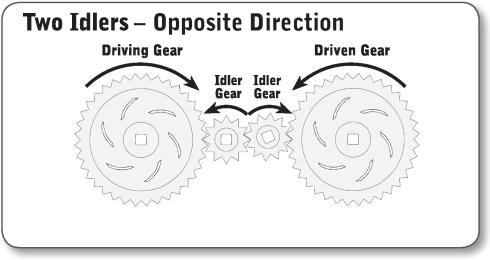
14 Idler Gears Gears can be inserted between the driving and driven gears. These are called idler gears, and they have no effect on the robot's gear ratio because their gear ratio contributions always cancel themselves out (because they are a driven gear relative to the first gear, and a driving gear relative to the last gear you first multiply by the number of teeth on the idler gear and then divide by the same number, which always cancels out). However, idler gears do reverse the direction of rotation. Normally, the driving gear and the driven gear turn in opposite directions. Adding an idler gear makes them turn in the same direction. Adding a second idler gear makes them turn in opposite directions again. Idler gears are typically used either to reverse the direction of spin between two gears or to transmit force from one gear to another gear far away (by using multiple idler gears to physically bridge the gap). 14 Autodesk's VEX Robotics Unit 6: Gears, Chains, and Sprockets

15 Think Phase 15
16 Compound Gear Ratio Compound gears are formed when you have more than one gear on the same axle. Compound gears are not to be confused with idler gears, as compound gears can affect the overall gear ratio of a system! In the compound gear system, there are multiple gear pairs. Each pair has its own gear ratio, but the pairs are connected to each other by a shared axle. The resulting compound gear system still has a driving gear and a driven gear, and still has a gear ratio (now called a compound gear ratio). The compound gear ratio between the driven and driving gears is then calculated by multiplying the gear ratios of each of the individual gear pairs. 16 Autodesk's VEX Robotics Unit 6: Gears, Chains, and Sprockets

17 Compound gears allow configurations with gear ratios that would not normally be achievable with the components available. In the example above, a compound gear ratio of 1:25 was achieved using only 12 and 60-tooth gears. This would give your robot the ability to turn an axle 25 times faster than normal (though it would only turn with 1/25th of the torque)! Gearing Design You can see how by using gear ratios you can affect the amount of loading applied to a motor by a mechanism. This is extremely important for mechanism design, because it is rare that the output of a motor is perfectly suited for a given application. As discussed in Unit 5: Speed, Power, Torque and DC Motors, the loading on the motor must be adjusted using gear to optimize system performance. Chain Drives Sprockets and chains are commonly used in applications where torque is needed to be transferred over longer distances than allowed by gears. Unlike spur gears, all of the sprockets in a chain drive rotate in the same direction. Think Phase 17


18 Chain Drives Roller chain is the most commonly used type of chain and has been in use since its invention late in the 19th century. It typically consists of rollers cushioned by bushings held in place by pins. These in turn are held in place by a set of roller link plates that are sandwiched between two link plates. You can find roller chains on bicycles and industrial machinery. Although very common, roller chains require constant lubrication and maintenance. Simpler cheaper versions without the bushings exist, but they are less durable and are reserved for less critical uses. Chains elongate while they are used so they must have some kind of adjustment or a convienient way to remove links to maintain proper tension. Roller chains incorporate a master link that can be removed easily to remove links. Most chain-drive mechanisms have some sort of tensioning device that can be adjusted without interrupting the operation of the device. 18 Autodesk's VEX Robotics Unit 6: Gears, Chains, and Sprockets


19 Sprockets Sprockets, although similar in appearance to gears from a distance, are distinctly different in design and use. Gears are designed to mesh directly with each other, while sprockets are incapable of directly meshing. They are specifically designed for meshing with a chain to transfer power. Other Types of Chains In light duty applications, plastic chains are finding their place. Although not as durable as metal chains, they do not need constant lubrication. Another advantage is they are easy to resize and do not have as many parts in their construction. The VEX Robotics System uses a plastic chain and matching sprockets. It is similar to a metal chain pintle design. Pintle chains are used in unprotected, dirty, or dusty environments where lubrication is not effective or desired. Think Phase 19
20 Chain Drive Gear Ratios The real nature of gear ratios is a little more complex than just counting teeth on gears. Gear ratio is actually defined as the number of rotations that the driving axle needs to make in order to turn the driven axle around once. When dealing with toothed gears, you can find the number of turns needed by counting teeth, as you have seen previously. All the gear ratios you have looked at so far have used spur gears. In sprocket and chain reductions, you can still count the teeth to find a gear ratio, because as with spur gears, the teeth count is proportional to the sprocket diameter. 20 Autodesk's VEX Robotics Unit 6: Gears, Chains, and Sprockets

21 Create Phase Overview This phase describes the creation and editing of spur, bevel, and worm gear sets. The Autodesk Inventor Design Accelerator application contains a specific gear generator for each type of gear. Gears are components that determine the speed, torque, and direction of power as it is transferred through a system. Properly designed gears transmit power smoothly and efficiently, thus reducing wear and impact on the system. By changing gear ratios, you can run machinery at optimum efficiency and adjust to changing conditions. Using Design Accelerator, you can identify multiple gear combinations, and validate their capabilities within your design. Protobot Gears The Protobot uses spur gears to drive the wheels and the arm as shown. Objectives After completing this phase, you will be able to: Describe gear generation in Design Accelerator. Describe options for spur, bevel, and worm gear generation. Use Design Accelerator to create spur gears. Animate a gear assembly. Create Phase 21
22 Prerequisites Before starting this phase, you must have: A working knowledge of the Windows operating system. Completed Unit 1: Introduction to VEX and Robotics > Getting Started with Autodesk Inventor. Completed Unit 2: Introduction to Autodesk Inventor > Quick Start for Autodesk Inventor. Technical Overview The following Autodesk Inventor tools are used in this phase: Icon Name Description Spur Gear Calculates dimensions and checks strength of external and internal gearing with straight and helical teeth. It contains geometric calculations for designing different types of correction distributions, including a correction with compensation of slips. Plane Use work planes when creating axes, sketch planes, or termination planes, or to position cross-sectional views or cutting planes. Use a work plane: When a part face is not available as a sketch plane for sketching new features. When an intermediate position is required to define other work planes (for example, at an angle to a face at an offset distance). 22 Create 2D Sketch A sketch consists of the sketch plane, a coordinate system, 2D curves, and the dimensions and constraints applied to the curves. Project Geometry Projects geometry (model edges, vertices, work axes, work points, or other sketch geometry) onto the active sketch plane as reference geometry. Circle Creates a circle from a center point and radius, or tangent to three lines. Dimension Adds dimensions to a sketch. Dimensions control the size of a part. They can be expressed as numeric constants, as variables in an equation, or in parameter files. Rectangle Use to create rectangles two ways: specifying diagonal corners or specifying length and width. Each rectangle side is a line segment. Vertical Constraint A geometric constraint that positions selected lines, ellipse axes, or pairs of points parallel to the Y-axis of the sketch coordinate system (same X coordinate). Horizontal Constraint The horizontal constraint causes lines, ellipse axes, or pairs of points to lie parallel to the X axis of the sketch coordinate system. Autodesk's VEX Robotics Unit 6: Gears, Chains, and Sprockets
23 Icon Name Description Equal Constraint A geometric constraint that causes selected arcs and circles to have the same radius or selected lines to have the same length. Fillet Placed features that round off or cap interior or exterior corners or features of a part. Mirror Use to mirror sketch geometry across a centerline. Rectangular Pattern Part, surface, and assembly features can be arranged in a pattern to represent hole patterns or textures, slots, notches, or other symmetrical arrangements. Chamfer Chamfers bevel part edges in both the part and assembly environments. Chamfers may be equal distance from the edge, a specified distance and angle from an edge, or a different distance from the edge for each face. ifeature An ifeature is one or more features that can be saved and reused in other designs. You can create an ifeature from any sketched feature that you determine to be useful for other designs. Features dependent on the sketched feature are included in the ifeature. After you create an ifeature and store it in a catalog, you can place it in a part by dragging it from Windows Explorer and dropping it in the part file or by using the Insert ifeature tool. Required Supplies and Software The following software is used in this phase: Software Autodesk Inventor Professional 2011 About Generating Gears The gear generators in Design Accelerator enable you to add gear models to your designs by entering data in a table format, and then validating your entries prior to producing the gear set. The gear generators automate the gear design process and reduce the time required to sketch and model gear data. The gear generators are designed so that you can add general information regarding the type of gear set selected and then provide data for the individual gears. At any time during this process, you can calculate the current data, preview the gear set in the graphics window, and review the calculations for possible issues. Create Phase 23


24 Spur Gears Component Generator You enter the gear design parameters to create the correct sized spur gear for the Protobot. Definition of Generated Gears The gear generators are where you enter gear data to produce gear models in your assemblies. After the required data is entered into the gear generator, the data is processed and models are produced based on the data provided. The data that you input into the gear generator and the resulting calculations are stored with the gear set. Because the values are stored as part of the generated gear set, you can review your results or revise your calculations at a later time. 24 Autodesk's VEX Robotics Unit 6: Gears, Chains, and Sprockets

25 Example: Generated Gears In the following illustration, a bevel gear set is created to change the direction and transmit power from the input shaft to the threaded rod. Now that the gear design has been finalized, the final shaft lengths can be determined, as well as the methods to secure the gears to the shafts. Gear Generator Options When you create or edit gear sets, you interact with the Gears Component Generator dialog box for the type of gear specified. The Design Accelerator enables you to efficiently design spur, bevel, and worm gear sets. To design and position your gear sets in your assemblies, you need to know what options are available in the dialog box and where they are located. The specific Gears Component Generator dialog box is displayed after you click the tool to generate gears. Within this dialog box, you enter the method and values required to calculate the gear set. The information varies depending on the method used. Each of the Gears Component Generator dialog boxes is divided into three main areas. In the Common area, you can specify the gear creation method and other information pertaining to the overall gear set. In the Gear1 and Gear2 areas, you can specify data that is specific to the individual gear. For example, for a bevel gear set, when you define the Cylindrical Face and Start Plane for each gear, the Shaft Angle is calculated and displayed in the Common area. Create Phase 25


26 Spur Gear Options The following options are available for creating spur gear sets. Enter data to design the gear set. Input power and speed requirements and review calculation results. Calculations are based on power and speed inputs, and information from the Design tab. 26 Autodesk's VEX Robotics Unit 6: Gears, Chains, and Sprockets

27 Specify information that applies to the entire gear set. Input data specific to the first gear. Input data specific to the second gear. Display a page containing all input data and calculations. Bevel Gear Options The following options are available for creating bevel gear sets. Enter data to design the gear set. Input power and speed requirements and review calculation results. Calculations are based on power and speed inputs, and information from the Design tab. Specify information that applies to the entire gear set. Input data specific to the first gear. Input data specific to the second gear. Display a page containing all input data and calculations. Create Phase 27

28 Worm Gear Options The following options are available for creating worm gear sets. Enter data to design the gear set. Input power and speed requirements and review calculation results. Calculations are based on power and speed inputs, and information from the Design tab. Specify information that applies to the entire gear set. Input data specific to the worm. Input data specific to the worm gear. Display a page containing all input data and calculations. 28 Autodesk's VEX Robotics Unit 6: Gears, Chains, and Sprockets

 From the Diametral Pitch list, select 24.0000 ul/in. (3) Verify that the Internal check box is not selected. (4) 5.")

29 Exercise: Generate Spur Gears In this exercise, you design two spur gears for the Protobot. The design parameters and an existing assembly are supplied to assist you with the gear design. 4. To set the Common values for the spur gear: Under Common, from the Design Guide list, select Number of Teeth. (1) From the Desired Gear Ratio list, select ul. (2) From the Diametral Pitch list, select ul/in. (3) Verify that the Internal check box is not selected. (4) 5. To define the values for Gear 1: Under Gear 1, click Cylindrical Face. Select the surface of the top shaft (1). Under Gear 1, click Start plane. Select the face (2). For Facewidth, enter The completed exercise Exercise: Create Spur Gears for the Protobot Make IFI_Unit6.ipj the active project. Open DesignGears.iam. The two parts represent a simplified design of the drive shafts from the Protobot. The center to center distance is set to two inches. 3. On the Design tab, Power Transmission panel, click Spur Gear. Create Phase 29


30 6. To define the values for Gear 2: In the Spur Gears Component Generator dialog box, under Gear 2, click Cylindrical Face. Select the surface of the lower shaft (1). Click Start plane. Select the face (2). For Facewidth, enter Review the updated calculation. The initial design fails as noted in red text in the summary window. 10. Under Gear 1, for Unit Correction, enter Click the chevron to resize the summary window. 8. To check your design, in the Spur Gears Component Generator dialog box, click Calculate. 11. To check your design again, click Calculate. The Unit Correction error for Gear 1 is resolved, as noted by the blue color of the text, but the design still fails. 12. Click the Calculation tab. 13. Under Method of Strength Calculation, select Legacy ANSI from the list. 14. Under Loads, for Power > Gear 1, enter 0.02 hp. 15. Click the Design tab. Click Calculate. The calculation indicates design compliance. 30 Autodesk's VEX Robotics Unit 6: Gears, Chains, and Sprockets


31 16. Click OK twice. The gears are created. 17. Drag the large gear. The gears rotate. 18. Save the file. 3. On the ViewCube, click Home. 4. On the Work Features panel, click Plane. 5. Move the cursor over the top edge of a gear tooth. Click when the center point of the edge is displayed as shown. 6. Click the edge of the same tooth to create a work plane through the center of the gear. 7. On the Sketch panel, click Create 2D Sketch. 8. Select the edge of the work plane. Create a Work Plane In this section of the exercise, you create a work plane through the spur gear In the browser, expand Spur Gears:1. Right-click Spur Gear1:1. Click Open. Create Phase 31
 when the large green dot and coincident constraint are displayed. Move the cursor to preview the circle.")

 For Distance, enter 0.")
. In the value input box, enter 0.375. (2) Click the checkmark. (3) 3. 4.")
32 9. Right-click in the graphics window. Click Slice Graphics. The gear is sliced along the new sketch. 5. Select the projected center point (1) when the large green dot and coincident constraint are displayed. Move the cursor to preview the circle In the browser, right-click the work plane. Click Visibility to turn off the work plane display. Extrude the Sketch In this section of the exercise, you extrude the center of the small spur gear. 1. On the Draw panel, click Project Geometry. 2. In the value input box, enter Press ENTER. 7. Press ESC to cancel the Circle tool. 8. On the ViewCube, click Home. 9. Press E to start the Extrude tool. 10. In the Extrude dialog box. Click Midplane. (1) For Distance, enter (2) Click OK. Select the top face of a gear tooth as shown. The edge and the center point of the gear are projected onto the sketch. 11. For Direct Manipulation. Select Symetric from the list. (1). In the value input box, enter (2) Click the checkmark. (3) On the ViewCube, click Front. On the Draw panel, click Circle. Autodesk's VEX Robotics Unit 6: Gears, Chains, and Sprockets
. Select the midpoint of the lower edge (2). 8.")
.")

33 12. Save the file. 5. Create a rectangle as shown. 6. On the Constrain panel, click Vertical Constraint. 7. Select the projected midpoint of the gear (1). Select the midpoint of the lower edge (2). 8. On the Constrain panel, click Horizontal Constraint. 9. Select the projected midpoint of the gear (1). Select the midpoint of the left edge (2). Create a Sketch In this section of the exercise, you create a sketch for the hole through the spur gear. 1. On the Sketch panel, click Create 2D Sketch Select the front face of the extruded circle. On the ViewCube, click Front. On the Draw panel, click Rectangle. 10. On the Constrain panel, click Equal Constraint. Create Phase 33


34 11. Select the two edges as shown. 17. Repeat this workflow to create the other three fillets. Tip: Instead of selecting two lines, select the corner. 12. On the Constrain panel, click Dimension. 13. Create a dimension on the top edge. 18. Press ESC to cancel the Fillet tool. Extrude the Sketch In this section of the exercise, you extrude the hole through the spur gear. 14. On the Draw panel, click Fillet On the ViewCube, click Home. Press E to start the Extrude tool. Select the rectangle as the profile. 4. For Operation, click Cut. 15. For Radius, enter Select the two edges as shown to create the first fillet. 34 Autodesk's VEX Robotics Unit 6: Gears, Chains, and Sprockets


35 5. Under Extents, select To Next from the list. 3. For color, select Green (Flat) from the list Click OK. 7. Save the file. Click Save. Click Done. In the browser, right-click Spur Gear1. Click iproperties. 7. Click the Physical tab. 8. For Material, select ABS Plastic from the list. 9. Click Apply. Note the updated properties of the gear, such as Mass, Area, and Volume. 10. Click Close. 11. Click Save. 12. Close the Spur Gear1 window, and return to the assembly. Note that the gear is updated in the assembly. Change the Material of the Gear In this section of the exercise, you change the material of the gear to ABS plastic. 1. On the Manage tab, Styles and Standards panel, click Styles Editor. 2. Expand Material. Select ABS Plastic. Create Phase 35

36 Extrude the Sketch on the Large Spur Gear In this section of the exercise, you extrude a sketch on the large spur gear. 1. In the browser, right-click Spur Gear2:1. Click Open. 2. On the ViewCube, click Home. 3. On the Sketch panel, click Create 2D Sketch Select the front face of the gear. On the ViewCube, click Front. On the Draw panel, click Circle. 7. Create a circle on the face of the gear. The center of the circle must be coincident with the projected center of the gear. In the value input box, enter Press ENTER Autodesk's VEX Robotics Unit 6: Gears, Chains, and Sprockets


37 9. On the ViewCube, click Home. 10. Press E to start the Extrude tool. 11. Select inside the circle as the profile. 16. On the Modify panel, click Fillet. 17. Select the inside edge of the extrusion. 18. For Radius, enter Click OK. 12. For Operation, select Cut. Mirror the Feature In this section of the exercise, you mirror the extrusion and the fillet. 1. On the Work Features panel, click Plane. 2. Move the cursor over the top edge of a gear tooth. Click when the center point of the edge is displayed as shown. 3. Click again to create a work plane through the center of the gear. 13. For Distance, enter Click the More tab. For Taper, enter Click OK. Create Phase 37

.")
38 4. On the Pattern panel, click Mirror. 5. Create a small circle on the face of the gear as shown. 5. In the browser, select the extrusion and fillet you created in the previous steps. You can also select the features in the graphics window. In the Mirror dialog box, click Mirror Plane. Select the work plane. Click OK. Rotate the gear to view the mirrored features. On the ViewCube, click Home. Turn off the visibility of the work plane. Extrude the Sketch for the Small Circle 6. On the Constrain panel, click Vertical Constraint. In this section of the exercise, you extrude the sketch for the small circle. 1. On the Sketch panel, click Create 2D Sketch. 7. Select the projected center of the gear (1). Select the center of the small circle (2). 8. On the Constrain panel, click Dimension. 9. Create a dimension on the circle Select the inside front face of the gear. On the ViewCube, click Front. On the Draw panel, click Circle. Autodesk's VEX Robotics Unit 6: Gears, Chains, and Sprockets


39 10. Create a dimension between the center of the gear and the center of the circle Press ESC to cancel the Dimension tool. Press E to start the Extrude tool. Select the small circle as the profile. For Distance, enter Click OK. Extrude the Sketch on the Back Face In this section of the exercise, you extrude a sketch on the back face of the gear Rotate the gear to view the back face. On the ViewCube, click Back. Using the workflow from the previous steps, create a new sketch on the back face. Create, constrain, and dimension a circle as shown. 4. On the ViewCube, click the top-right corner. 5. Extrude the circle a distance of Create a new sketch on the face of the extrusion. Create and dimension a diameter circle as shown. 7. Create Phase 39


40 8. Extrude the circle using the Cut operation for a distance of Click OK. Create a Feature Pattern Create the Hole In this section of the exercise, you create a hole On the ViewCube, click Home. Create a new sketch on the face of the small extrusion. Press H to start the Hole tool. Select the projected center of the sketch. For Hole Diameter, enter For Termination, select Through All from the list. In this section of the exercise, you create a feature pattern of the extruded and hole features. 1. On the ViewCube, click Home. 2. On the Pattern panel, click Rectangular. 3. In the browser, select the three extruded features and the hole feature. Autodesk's VEX Robotics Unit 6: Gears, Chains, and Sprockets


 For Spacing, enter 0.5. (2) 2. In the browser, expand Rectangular Pattern1.")

41 4. Click the Direction 1 Path selection button. 5. In the browser, expand the Origin folder. Select X Axis Click the Direction 2 Path selection button. In the browser, select Y Axis. For Count, enter 5. For Spacing, enter 0.5. Click OK. Suppress Pattern Occurrences In this section of the exercise, you suppress five of the pattern occurrences Under Direction 1, select the Midplane check box For Count, enter 5. (1) For Spacing, enter 0.5. (2) 2. In the browser, expand Rectangular Pattern1. You now suppress five occurrences. In the browser, move the cursor over each occurrence, noting which features are highlighted on the gear. When the bottom right occurrence (1) is highlighted, right-click the occurrence. Click Suppress. Create Phase 41


42 3. Repeat this workflow for the other four occurrences. Add the Center Feature 11. Select the small circle as the profile. 12. For Distance, enter Click OK. 14. Rotate the gear to view the back face. 15. Using the workflow from the previous steps, create a new sketch on the back face. Create and dimension a inch diameter circle as shown. In this section of the exercise, you create the center feature on the gear. 1. On the Sketch panel, click Create 2D Sketch Select the front face of the gear. On the ViewCube, click Front. On the Draw panel, click Circle. 16. Extrude the circle a distance of Create a small circle in the center of the gear as shown. 6. On the Constrain panel, click Dimension. 17. On the ViewCube, click Home. 18. On the Modify panel, click Chamfer Create a dimension on the circle. Press ESC. On the ViewCube, click Home. Press E to start the Extrude tool. Autodesk's VEX Robotics Unit 6: Gears, Chains, and Sprockets


43 19. Select the edge as shown. 3. Select Workspace to navigate to your working folder. 20. For Distance, enter Click OK Select SquareHole.ide. Click Open. Select the front face of the extrusion. Note that a check mark is added to Profile Plane1 in the dialog box. 6. Click Finish. 22. Save the file. Insert an ifeature In this section of the exercise, you insert an ifeature for the square hole in the gear. Note that this is an improved design from the square hole created on the small spur gear. An ifeature is one or more features that can be saved and reused in other designs. This ifeature was extracted from another gear. 1. On the Manage tab, Insert panel, click Insert ifeature. 2. Click Browse. The default location for ifeatures is displayed. Change the Material In this section of the exercise, you change the material to ABS plastic. 1. On the Manage tab, Styles and Standards panel, click Styles Editor. Create Phase 43
44 2. Expand Material. Select ABS Plastic. 3. For color, select Green (Flat) from the list Click Save. Click Done. In the browser, right-click Spur Gear2. Click iproperties. 7. Click the Physical tab. 8. For Material, select ABS Plastic. 9. Click Apply. Note the properties of the gear, such as Mass, Area, and Volume. 10. Click Close. 11. Click Save. 12. Close the Spur Gear2 window. Return to the assembly. Note that the gear is updated in the assembly. 13. Save the file. 44 Autodesk's VEX Robotics Unit 6: Gears, Chains, and Sprockets


45 Exercise: Animate a Gear Assembly In this exercise, you animate the arm mechanism by driving an existing assembly constraint. 4. Right-click the end of the shaft. Click Find in Browser. The completed exercise Exercise: Animate a Gear Assembly Make IFI_Unit6.ipj the active project. Open Arm-Assembly.iam. The shaft is highlighted in the browser. In this example, it is SHAFT-3000:5. 3. In the browser, expand Representations > View. Right-click Drive Train. Click Activate. Motion is provided by the motor (1), which drives the shaft (2). The two small gears (3) then drive the arm mechanism. Create Phase 45

.")


46 5. In the browser, expand SHAFT-3000:5. Locate Drive This Constraint (0.00 deg). This is a zero degree angle constraint between the shaft and the frame. 6. Right-click Drive This Constraint (0.00 deg). Click Suppress to turn on suppress. 7. In the graphics window, click and drag the small gear. The large gear and the arm mechanism also move. 8. In the browser, right-click Drive This Constraint (0.00 deg). Click Suppress to turn off suppress In the browser, expand Representations > View. Right-click Home. Click Activate. Note: If the arm assembly does not return to the position shown, suppress the constraint again, drag the arm close to the position shown, and then unsuppress the constraint. 10. Scroll back to SHAFT-3000:5. Right-click Drive This Constraint (0 deg). Click Drive Constraint. 11. In the Drive Constraint dialog box, click More. Autodesk's VEX Robotics Unit 6: Gears, Chains, and Sprockets

47 12. In the Drive Constraint dialog box: For Start, enter -30 deg. For End, enter 30 deg. Under Increment, for Amount of Value, enter 2. Under Repetitions, click Start/End/Start. Under Repetitions, enter Click Forward. Note: The start and end values set a range of 60 degrees, but the arm does not seem to move that much. This is because the constraint is driving the small gear. 14. Click Cancel. The arm mechanism returns to the original position. 15. Close the file. Do not save changes. Create Phase 47
48 Build Phase Overview In this phase, you experiment with different gear ratios using the test stand that you built in Unit 5. Phase Objectives After completing this phase, you will be able to: Describe the relationship between gearing, speed, and power. Incorporate VEX gears into a design. Prerequisites Before starting this phase, you must have: Completed Unit 6: Gears, Chains, and Sprockets > Think Phase. Have an assembled VEX motor test stand from the Unit 5: Speed, Power, Torque, and DC Motors > Build Phase. Related phase resources are: Unit 1: Introduction to VEX and Robotics 48 Autodesk's VEX Robotics Unit 6: Gears, Chains, and Sprockets
49 Unit 4: Microcontroller and Transmitter Overview Unit 5: Speed, Power, Torque, and DC Motors Required Supplies and Software The following supplies are used in this phase: Supplies Notebook and pen One assembled VEX motor test stand from the Unit 5: Speed, Power, Torque, and DC Motors > Build Phase Work surface Small storage container for loose parts Optional: Autodesk Inventor Professional 2009 VEX Parts The following VEX parts are used in this phase: Quantity Part Number Abbreviations 5 BEARING-FLAT BF 10 NUT-832-KEPS NK 10 SCREW S4 2 SHAFT-3000 SQ3 2 SHAFT-COLLAR COL 1 SPACER-THICK SP2 1 SPACER-THIN SP1 1 VEX-12-TOOTH-GEAR G12 1 VEX-84-TOOTH-GEAR G84 2 WASHER-DELRIN WP Build Phase 49

50 Activity Gear Ratio Test Stand In this activity, you add a single-stage gear reduction to the test stand from Unit 5 to enable the lifting of heavier objects. As you work on building this project, have some of your team members focus on expanding their expertise using Autodesk Inventor software. Later in the curriculum, you will be challenged to come up with your own creative solutions for robot design. You will save time and maximize your ability to create winning solutions if your team understands how to leverage the power of digital prototypes using Inventor. Note: Team members can download a free version of Autodesk Inventor Professional software to use at home, so you can come to class prepared to build and test your best ideas! To do this, simply join the Autodesk Education Community at 1. To complete the next step: Remove the 1x2x1x15 C-Channel from the existing test stand. Remove the motor from the 1x2x1x15 C-Channel. The completed model is as shown: 50 Autodesk's VEX Robotics Unit 6: Gears, Chains, and Sprockets
51 2. To complete the next step: Re-bolt the motor into its new position on the 1x2x1x15 C-Channel. Bolt the two Bearing Flats [BF] to the 1x2x1x15 C-Channel. The completed model is as shown: Build Phase 51

52 3. To complete the next step: Bolt four Bearing Flats to the test stand. The completed model is as shown: 52 Autodesk's VEX Robotics Unit 6: Gears, Chains, and Sprockets
![4. To complete the next step: Slide the 84 Tooth Gear [G84] and a Thick Spacer [SP2] onto the 4" shaft from the test stand.](/docs-images/89/100997691/images/53-1.jpg "Slide two Collars [COL], a 12 Tooth Gear [G12], a Thin Spacer [SP1], and 2 Delrin Washers [WP] on a 3\" shaft [SQ3]. Insert the 3\" Shaft into the Bearing Flat.")
53 4. To complete the next step: Slide the 84 Tooth Gear [G84] and a Thick Spacer [SP2] onto the 4" shaft from the test stand. Slide two Collars [COL], a 12 Tooth Gear [G12], a Thin Spacer [SP1], and 2 Delrin Washers [WP] on a 3" shaft [SQ3]. Insert the 3" Shaft into the Bearing Flat. Bolt the assembly from the previous step to the 2" Standoffs on the test stand. Insert the 3" Shaft fully into the Motor and tighten the two Shaft Collars. Slide the 84 Tooth Gear and Thick Spacer up against the Bearing Flat you attached to the 1x2x1x15 C-Channel and tighten the Shaft Collars. Ensure that the 84 Tooth Gear and 12 Tooth Gear are aligned such that the teeth mesh. Build Phase 53

54 The completed model is as shown: Your test stand is now complete and ready for use. Autodesk's VEX Robotics Unit 6: Gears, Chains, and Sprockets
55 Amaze Phase Overview In this phase, you try to lift a 5 lb. weight as quickly as possible using the modified test stand from the Unit 6: Gears, Chains, and Sprockets > Build Phase. Phase Objectives After completing this phase, you will be able to: Modify the gearing of a VEX gearbox. Describe the effect of gear ratios on speed and torque. Determine an appropriate gear ratio to complete a mechanical task. Prerequisites and Resources Before starting this phase, you must have: Completed the Unit 6: Gears, Chains, and Sprockets > Think Phase. Completed the Unit 6: Gears, Chains, and Sprockets > Build Phase. Have assembled the gear ratio test stand from the Unit 6: Gears, Chains, and Sprockets > Build Phase. Unit 1: Introduction to VEX and Robotics Unit 4: Microcontroller and Transmitter Overview Unit 5: Speed, Power, Torque, and DC Motors Required Supplies and Software The following supplies are used in this phase: Supplies An assembled gear ratio test stand from the Unit 6: Gears, Chains, and Sprockets > Build Phase Notebook and pen 5 lb. weight One stopwatch A surface (for example, a table or desk) with an edge at least 24 above the ground Amaze Phase 55
56 VEX Parts The following VEX parts are used in this phase: Quantity Part Number Abbreviations 1 VEX-36-TOOTH-GEAR G36 1 VEX-60-TOOTH-GEAR G60 Evaluation Gear Ratio Challenge Using the Gears Ratio Test Stand, determine the gear ratio that enables you to lift the 5 lb. weight as fast as possible. Determine Gear Ratio Challenge 1. Looking back at Unit 5: Speed, Power, Torque, and DC Motors > Think Phase, remember that you can alter the speed of a system by changing the gear ratios. The smaller the reduction, the faster the output speed, but with a less amount of torque. The key to this exercise is to find the smallest reduction that still has enough torque to lift the 5 lb. mass. 2. In this phase, you test five different gear ratios: 12:84, 12:60, 36:84, 36:60, and 60:84. To do each of these tests, the Gear Ration Test Stand needs to be modified appropriately. 3. Plug the motor into Port 6 of your Microcontroller. 4. Plug the Transmitter into Port 1 of the Microcontroller. 5. Plug the 7.2V battery into the Microcontroller. 6. Turn both your Transmitter and Microcontroller on. 7. Using the yellow buttons on the back of the Transmitter, you should be able to control the rotation of the pulley. 8. Set up the test stand between two tables, with the string hanging between them. Let the string hang 24 below the surface top. 9. Attach the 5 lb. mass to the string. 10. Using the Transmitter, have the test stand lift the mass. Using the stopwatch, time how long it takes for the mass to reach the surface. Record this time in your engineering notebook. If the test stand is unable to generate enough torque to lift the mass, record it in your chart. How to Change the Gear Ratio 1. Remove the 1x2x1x15 C-Channel that the motor is attached to by removing the bolts at either end of the channel. 2. Remove the motor and bearing flat from the 1x2x1x15 C-Channel, and reattach it to the proper holes for the new gear ratio. See figures 1-5 to determine the proper mounting location. 3. Remove the spacers from both the drive and driven shafts. Place these spacers in separate piles, so they can easily be put back on the appropriate shafts. 4. Remove both the drive and driven gears. 5. Loosen and remove both collars on the drive shaft. 6. Remove the drive shaft from the bearing flat. 56 Autodesk's VEX Robotics Unit 6: Gears, Chains, and Sprockets
57 7. Depending on your new ratio, insert the drive shaft into its new appropriate bearing flat. Refer to the following figures Replace both collars on the drive shaft. 9. Slide the appropriate gears onto their shafts. Make sure the gears are aligned such that they mesh properly. 10. Replace the spacers on the shafts. 11. Reattach the 1x2x1x15 C-Channel. 12. Your test stand is now ready for operation with your new gear ratio. Figure 1: 12:84 Reduction Amaze Phase 57

58 Figure 2: 12:60 Reduction 58 Autodesk's VEX Robotics Unit 6: Gears, Chains, and Sprockets
59 Figure 3: 36:84 Reduction Amaze Phase 59
60 Figure 4: 36:60 Reduction 60 Autodesk's VEX Robotics Unit 6: Gears, Chains, and Sprockets
61 Figure 5: 60:84 Reduction Amaze Phase 61
62 Engineering Notebook Create the following blank chart in your engineering notebook: Drive Gear Driven Reduction Gear Ratio Pulley Free Speed (RPM) Calculated Motor Torque Time to lift 24" 1. Using the knowledge you gained on gearing, speed, power, and torque in the previous Think Phases, complete your chart appropriately. Remember the following: Reduction Ratio = # teeth of drive gear / # teeth of driven gear Free Speed = Motor Free Speed x Reduction Ratio. Go back to your notes from the Unit 5: Gears, Chains, and Sprocket > Amaze Phase, where you calculated the free speed of a VEX motor. Motor Torque = Mass x Pulley Radius x Reduction Ratio 2. Create a graph showing the relationship between the Reduction Ratio and Time to Lift the mass. 3. In your notebook, discuss the shape of your graph. Does it surprise you? 4. How can you lift the mass even faster using this test stand? How would it need to be modified? Discuss what changes you would make to accomplish this task. If time remains, execute your plan. Presentation Prepare your findings from this phase, and present them to the class. Explain why you and your classmates may not all have the same results. Discuss how you can modify the test stand to lift the weight even faster. 62 Autodesk's VEX Robotics Unit 6: Gears, Chains, and Sprockets

63 STEM Connections Background The United States Coast Guard often uses rescue helicopters when responding to maritime emergencies. These helicopters can assist in rescue efforts by hovering above their target and inserting a rescue swimmer whose job it is to reach the survivor and stay with them until both swimmers can be extracted via a rescue line from the helicopter. The helicopter extraction is accomplished with a winch system similar to the VEX Test Stand you use for this unit. Science Coast Guard rescue helicopters often operate in extreme conditions. As a result, the winch systems involved in ocean rescue must be able to withstand the harsh ocean environment. What are some of the material science transformation processes (for example, corrosion) that you need to consider when designing a winch for this sort of application? What associated problems can occur if the winch system is not designed to resist these harsh conditions? What materials can you use to build a weather resistant winch system, and how do those materials affect the operation of the winch? Design a laboratory test to determine which materials are the best choice for these conditions. Technology Consider that the helicopter's winch system may be subject to very different loads, given different rescue circumstances. For instance, the weight of the survivors, the number of survivors, and the weather and water conditions can all affect the load. How would a system that switches gear ratios based on the potential load improve the efficiency of the rescue winch system? How can this be accomplished? STEM Connections 63
Autodesk's VEX Robotics Curriculum. Unit 6: Gears, Chains, and Sprockets
 Autodesk's VEX Robotics Curriculum Unit 6: Gears, Chains, and Sprockets 1 Overview In Unit 6: Gears, Chains, and Sprockets, you modify the VEX test stand from Unit 5: Speed, Power, Torque, and DC Motors
Autodesk's VEX Robotics Curriculum. Unit 10: Drivetrain Design 2
 Autodesk's VEX Robotics Curriculum Unit 10: Drivetrain Design 2 1 Overview In Unit 10: Drivetrain Design 2, you design your own drivetrain, building on knowledge and skills from previous units. You also
Autodesk's VEX Robotics Curriculum. Unit 9: Drivetrain Design 1
 Autodesk's VEX Robotics Curriculum Unit 9: Drivetrain Design 1 1 Overview In Unit 9: Drivetrain Design 1, you learn the basic principles of drivetrain design, build a basic VEX drivetrain, and test your
Autodesk's VEX Robotics Curriculum. Unit 5: Speed, Power, Torque, and DC Motors
 Autodesk's VEX Robotics Curriculum Unit 5: Speed, Power, Torque, and DC Motors 1 Overview In Unit 5: Speed, Power, Torque, and DC Motors, you build a VEX test stand winch that enables you to learn key
Autodesk's VEX Robotics Curriculum. Unit 14: Accumulator Design
 Autodesk's VEX Robotics Curriculum Unit 14: Accumulator Design 1 Overview In Unit 14: Accumulator Design, you learn about the use and design of accumulators. You design your own accumulator, report on
Unit 1 Introduction to VEX and Robotics
 Unit Overview Unit 1 Introduction to VEX and Robotics VEX lab kits bring robotics into the classroom, making it a fun and educational experience for all. In this introductory unit, you review the kit and
Simple Gears and Transmission
 Simple Gears and Transmission Simple Gears and Transmission page: of 4 How can transmissions be designed so that they provide the force, speed and direction required and how efficient will the design be?
Simple Gears and Transmission
 Simple Gears and Transmission Contents How can transmissions be designed so that they provide the force, speed and direction required and how efficient will the design be? Initial Problem Statement 2 Narrative
ROBOTICS BUILDING BLOCKS
 ROBOTICS BUILDING BLOCKS 2 CURRICULUM MAP Page Title...Section Estimated Time (minutes) Robotics Building Blocks 0 2 Imaginations Coming Alive 5...Robots - Changing the World 5...Amazing Feat 5...Activity
Introduction to Tube and PipeChapter1:
 Chapter 1 Introduction to Tube and PipeChapter1: This chapter introduces you to the tube and pipe environment in Autodesk Inventor Professional. Using the tube and pipe environment, you can create rigid
ME Week 5 Project 1 Gear Generator
 1 Project 1 - Generate and Edit Gears In this project, you create spur and bevel gear sets. You edit the gears to provide clearance for the shafts. 1.1 Create Spur Gears In this section of the project,
All levers are one of three types, usually called classes. The class of a lever depends on the relative position of the load, effort and fulcrum:
 Página 66 de 232 Mechanisms A mechanism is simply a device which takes an input motion and force, and outputs a different motion and force. The point of a mechanism is to make the job easier to do. The
Introduction. Kinematics and Dynamics of Machines. Involute profile. 7. Gears
 Introduction The kinematic function of gears is to transfer rotational motion from one shaft to another Kinematics and Dynamics of Machines 7. Gears Since these shafts may be parallel, perpendicular, or
MECHANISMS. AUTHORS: Santiago Camblor y Pablo Rivas INDEX
 MECHANISMS AUTHORS: Santiago Camblor y Pablo Rivas INDEX 1 INTRODUCTION 2 LEVER 3 PULLEYS 4 BELT AND PULLEY SYSTEM 5 GEARS 6 GEARS WITH CHAIN 7 WORM GEAR 8 RACK AND PINION 9 SCREW AND NUT 10 CAM 11 ECCENTRIC
Smart Spinner. Age 7+ Teacher s Notes. In collaboration with NASA
 Smart Spinner Age 7+ Teacher s Notes In collaboration with NASA LEGO and the LEGO logo are trademarks of the/sont des marques de commerce de/son marcas registradas de LEGO Group. 2012 The LEGO Group. 190912
CHAPTER 6 GEARS CHAPTER LEARNING OBJECTIVES
 CHAPTER 6 GEARS CHAPTER LEARNING OBJECTIVES Upon completion of this chapter, you should be able to do the following: Compare the types of gears and their advantages. Did you ever take a clock apart to
Driver Driven. InputSpeed. Gears
 Gears Gears are toothed wheels designed to transmit rotary motion and power from one part of a mechanism to another. They are fitted to shafts with special devices called keys (or splines) that ensure
LEGO Education WeDo 2.0 Toolbox
 LEGO Education WeDo 2.0 Toolbox WeDo 2.0 Table of Contents Program with WeDo 2.0 3-21 Build with WeDo 2.0 22-36 Program with WeDo 2.0 Programming is an important part of twenty-first century learning,
(POWER TRANSMISSION Methods)
") UNIT-5 (POWER TRANSMISSION Methods) It is a method by which you can transfer cyclic motion from one place to another or one pulley to another pulley. The ways by which we can transfer cyclic motion are:-
UNIT-5 (POWER TRANSMISSION Methods) It is a method by which you can transfer cyclic motion from one place to another or one pulley to another pulley. The ways by which we can transfer cyclic motion are:-
Part VII: Gear Systems: Analysis
 Part VII: Gear Systems: Analysis This section will review standard gear systems and will provide the basic tools to perform analysis on these systems. The areas covered in this section are: 1) Gears 101:
UNIT -I. Ans: They are specified by the no. of strands & the no. of wires in each strand.
 VETRI VINAYAHA COLLEGE OF ENGINEERING AND TECHNOLOGY, THOTTIAM, NAMAKKAL-621215. DEPARTMENT OF MECHANICAL ENGINEERING SIXTH SEMESTER / III YEAR ME6601 DESIGN OF TRANSMISSION SYSTEM (Regulation-2013) UNIT
Automate Your Designs A Hands-On Experience
 Craig Ruchti, Solid Edge Field Support Applications Engineer Automate Your Designs A Hands-On Experience Solid Edge University 2014 May 12-14, Atlanta, GA, USA SOLID EDGE UNIVERSITY 2014 Re-imagine What
CH#13 Gears-General. Drive and Driven Gears 3/13/2018
 CH#13 Gears-General A toothed wheel that engages another toothed mechanism in order to change the speed or direction of transmitted motion The gear set transmits rotary motion and force. Gears are used
ME6601 DESIGN OF TRANSMISSION SYSTEMS
 SYED AMMAL ENGINEERING COLLEGE (Approved by the AICTE, New Delhi, Govt. of Tamilnadu and Affiliated to Anna University, Chennai) Established in 1998 - An ISO 9001:2008 Certified Institution Dr. E.M.Abdullah
11. GEAR TRANSMISSIONS
 11. GEAR TRANSMISSIONS 11.1. GENERAL CONSIDERATIONS Gears are one of the most important elements used in machinery. There are few mechanical devices that do not have the need to transmit power and motion
Reliable Reach. Robotics Unit Lesson 4. Overview
 Robotics Unit Lesson 4 Reliable Reach Overview Robots are used not only to transport things across the ground, but also as automatic lifting devices. In the mountain rescue scenario, the mountaineers are
GEAR CONTENTS POWER TRANSMISSION GEAR TYPES OF GEARS NOMENCLATURE APPLICATIONS OF GEARS VELOCITY RATIO GEAR TRAINS EXAMPLE PROBLEMS AND QUESTIONS
 GEAR CONTENTS POWER TRANSMISSION GEAR TYPES OF GEARS NOMENCLATURE APPLICATIONS OF GEARS VELOCITY RATIO GEAR TRAINS EXAMPLE PROBLEMS AND QUESTIONS GEAR.. Power transmission is the movement of energy from
motion table of contents: squarebot assembly 3.2 concepts to understand 3.3 subsystems interfaces 3.21 motion subsystem inventory 3.
 The subsystem of the robot is responsible for exactly that,. It includes both the motors that generate, and the wheels and gears that transfer and transform that into the desired forms. With the structural
Motion. Table of Contents: Introduction to the Motion Subsystem 3.2. Concepts to Understand 3.8. Subsystem Interactions Motion.
 The Motion Subsystem of the robot is responsible for exactly that, motion. It includes both the motors that generate motion, and the wheels and gears that transfer and transform that motion into the desired
Working with VEX Parts
 VEX Robotics Design System VEX Classroom Lab Kit The VEX Robotics Design System is divided up into several different Subsystems: Structure Subsystem Motion Subsystem Power Subsystem Sensor Subsystem Logic
12/6/2013 9:09 PM. Chapter 13. Gears General. Dr. Mohammad Suliman Abuhaiba, PE
 Chapter 13 Gears General 1 2 Chapter Outline 1. Types of Gears 2. Nomenclature 3. Conjugate Action 4. Involute Properties 5. Fundamentals 6. Contact Ratio 7. Interference 8. The Forming of Gear Teeth 9.
1/2/2015 2:04 PM. Chapter 13. Gears General. Dr. Mohammad Suliman Abuhaiba, PE
 Chapter 13 Gears General 1 2 Chapter Outline 1. Types of Gears 2. Nomenclature 3. Conjugate Action 4. Involute Properties 5. Fundamentals 6. Contact Ratio 7. Interference 8. The Forming of Gear Teeth 9.
Applications in Design & Engine. Analyzing Compound, Robotic Machines
 v2.1 Compound Machines ering Applications in Design & Engine Analyzing Compound, Robotic Machines Educational Objectives At the conclusion of this lesson, students should be able to: Understand the relationship
Chain Drives. Pitch. Basic Types -There are six major types of power-
 1 2 Power transmission chains have two things in common; side bars or link plates, and pin and bushing joints. The chain articulates at each joint to operate around a toothed sprocket. The pitch of the
Marine Engineering Exam Resource Review of Couplings
 1. What are rigid couplings used for? Used to join drive shafts together. True alignment and rigidity are required. Example Drive shafts and production lines, bridge cranes, solid shaft that needs to be
LESSON Transmission of Power Introduction
 LESSON 3 3.0 Transmission of Power 3.0.1 Introduction Earlier in our previous course units in Agricultural and Biosystems Engineering, we introduced ourselves to the concept of support and process systems
Gears and Sprockets for Basic Robotics
 Gears and Sprockets for Basic Robotics Written by George Gillard Published: 24-May-2016 Introduction Gears and Sprockets are powerful tools in robotics. They can be used to make something spin or move
Foundations of Physical Science. Unit 2: Work and Energy
 Foundations of Physical Science Unit 2: Work and Energy Chapter 4: Machines and Mechanical Systems 4.1 Force and Machines 4.2 The Lever 4.3 Designing Gear Machines Learning Goals Describe and explain a
KISSsys 03/2015 Instruction 010
 KISSsys 03/2015 Instruction 010 Positioning 07/04/2015 KISSsoft AG Rosengartenstrasse 4 8608 Bubikon Switzerland Tel: +41 55 254 20 50 Fax: +41 55 254 20 51 info@kisssoft.ag www.kisssoft.ag Contents 1.
Moments. It doesn t fall because of the presence of a counter balance weight on the right-hand side. The boom is therefore balanced.
 Moments The crane in the image below looks unstable, as though it should topple over. There appears to be too much of the boom on the left-hand side of the tower. It doesn t fall because of the presence
Design of Helical Gear and Analysis on Gear Tooth
 Design of Helical Gear and Analysis on Gear Tooth Indrale Ratnadeep Ramesh Rao M.Tech Student ABSTRACT Gears are mainly used to transmit the power in mechanical power transmission systems. These gears
Catalog Q Conversion For those wishing to ease themselves into working with metric gears
 1.3.4 Conversion For those wishing to ease themselves into working with metric gears by looking at them in terms of familiar inch gearing relationships and mathematics, Table 1-5 is offered as a means
Graphical representation of a gear
 Homework 4 Gears Gears are designed to transmit rotary motion. Often they are arranged in a gear train (meshed together). Gear trains provide a change in speed, torque (turning force) and direction (clockwise
Lecture (7) on. Gear Measurement. By Dr. Emad M. Saad. Industrial Engineering Dept. Faculty of Engineering. Fayoum University.
 on. Gear Measurement. By Dr. Emad M. Saad. Industrial Engineering Dept. Faculty of Engineering. Fayoum University.") 1 Lecture (7) on Gear Measurement Fayoum University By Dr. Emad M. Saad Industrial Engineering Dept. Faculty of Engineering Fayoum University Faculty of Engineering Industrial Engineering Dept. 2015-2016
1 Lecture (7) on Gear Measurement Fayoum University By Dr. Emad M. Saad Industrial Engineering Dept. Faculty of Engineering Fayoum University Faculty of Engineering Industrial Engineering Dept. 2015-2016
GPK for Design and Rating of Industrial Gearboxes
 GPK for Design and Rating of Industrial Gearboxes KISSsys models: Bevel-Helical gear package includes KISSsys models for single bevel gearbox (right angle gearbox) and bevel gearboxes including one to
Chapter seven. Gears. Laith Batarseh
 Chapter seven Gears Laith Batarseh Gears are very important in power transmission between a drive rotor and driven rotor What are the functions of gears? - Transmit motion and torque (power) between shafts
Introduction to Manual Transmissions & Transaxles
 Introduction to Manual Transmissions & Transaxles Learning Objectives: 1. Identify the purpose and operation of transmissions. 2. Describe torque and torque multiplication. 3. Determine gear ratios. 4.
Chapter 7: DC Motors and Transmissions. 7.1: Basic Definitions and Concepts
 Chapter 7: DC Motors and Transmissions Electric motors are one of the most common types of actuators found in robotics. Using them effectively will allow your robot to take action based on the direction
Tutorial: Calculation of two shafts connected by a rolling bearing
 Tutorial: Calculation of two shafts connected by a rolling bearing This tutorial shows the usage of MESYS shaft calculation with multiple shafts. The shaft calculation software provides different views
What Are Gears? What Do They Do?
 What Are Gears? What Do They Do? Pre-Lesson Quiz 1. What is a gear? 2. List as many examples as you can of gears or objects that use gears. 2 Pre-Lesson Quiz Answers 1. What is a gear? A gear is a wheel
The Available Solution CYCLO DRIVE. Gearmotors & Speed Reducers. Series
 The Available Solution CYCLO DRIVE Gearmotors & Speed Reducers 6000 Series WHAT DO YOU THINK OF THIS? THESE ARE THE ADVANTAGES OF THE NEWEST CYCLO, 6000 SERIES: More frame sizes, gear ratios and motor
NEW CAR TIPS. Teaching Guidelines
 NEW CAR TIPS Teaching Guidelines Subject: Algebra Topics: Patterns and Functions Grades: 7-12 Concepts: Independent and dependent variables Slope Direct variation (optional) Knowledge and Skills: Can relate
Mechanical Power Transmission. September 16, 2008
 2008 TE Sessions Supported by Mechanical Power Transmission September 16, 2008 www.robojackets.org Goals Hand out kits to teams that don t have one. More physics concepts and terms Understanding key devices
KISSsoft 03/2018 Tutorial 7
 KISSsoft 03/2018 Tutorial 7 Roller bearings KISSsoft AG T. +41 55 254 20 50 A Gleason Company F. +41 55 254 20 51 Rosengartenstr. 4, 8608 Bubikon info@kisssoft.ag Switzerland www.kisssoft.ag Sharing Knowledge
How to Build with the Mindstorm Kit
 How to Build with the Mindstorm Kit There are many resources available Constructopedias Example Robots YouTube Etc. The best way to learn, is to do Remember rule #1: don't be afraid to fail New Rule: don't
Different types of gears. Spur gears. Idler gears. Worm gears. Bevel gears. Belts & Pulleys
 GEARS Robot Gears By using different gear diameters, you can exchange between rotational (or translation) velocity and torque. by looking at the motor datasheet you can determine the output velocity and
KISSsoft 03/2013 Tutorial 15
 KISSsoft 03/2013 Tutorial 15 Bevel gears KISSsoft AG Rosengartenstrasse 4 8608 Bubikon Switzerland Tel: +41 55 254 20 50 Fax: +41 55 254 20 51 info@kisssoft.ag www.kisssoft.ag Contents 1 Starting KISSsoft...
Basic Unit of Mechanical Drive Systems MDSU. Engineering and Technical Teaching Equipment INTRODUCTION GENERAL DESCRIPTION
 Basic Unit of Mechanical Drive Systems Engineering and Technical Teaching Equipment MDSU Electronic console INTRODUCTION Mechanical drive systems and their applications are widely used in industry and
Bevel Gears. Fig.(1) Bevel gears
 Bevel gears") Bevel Gears Bevel gears are cut on conical blanks to be used to transmit motion between intersecting shafts. The simplest bevel gear type is the straighttooth bevel gear or straight bevel gear as can be
Bevel Gears Bevel gears are cut on conical blanks to be used to transmit motion between intersecting shafts. The simplest bevel gear type is the straighttooth bevel gear or straight bevel gear as can be
Math is Not a Four Letter Word FTC Kick-Off. Andy Driesman FTC4318 Green Machine Reloaded
 1 Math is Not a Four Letter Word 2017 FTC Kick-Off Andy Driesman FTC4318 Green Machine Reloaded andrew.driesman@gmail.com 2 Goals Discuss concept of trade space/studies Demonstrate the importance of using
 DEPARTMENT OF MECHANICAL ENGINEERING Subject code: ME6601 Subject Name: DESIGN OF TRANSMISSION SYSTEMS UNIT-I DESIGN OF TRANSMISSION SYSTEMS FOR FLEXIBLE ELEMENTS 1. What is the effect of centre distance
TECHNOLOGY MECHANISMS
 TECHNOLOGY MECHANISMS 3º ESO IES CHAN DO MONTE URTAZA 1 WHAT IS A MECHANISM? Mechanism are devices that have been designed to make jobs easier. They all have certain things in common: They involve some
2010 National Edition correlated to the. Creative Curriculum Teaching Strategies Gold
 2010 National Edition correlated to the Creative Curriculum Teaching Strategies Gold 2015 Big Day for PreK is a proven-effective comprehensive early learning program that embraces children's natural curiosity
Linear Shaft Motors in Parallel Applications
 Linear Shaft Motors in Parallel Applications Nippon Pulse s Linear Shaft Motor (LSM) has been successfully used in parallel motor applications. Parallel applications are ones in which there are two or
KINEMATICS OF MACHINARY UBMC302 QUESTION BANK UNIT-I BASICS OF MECHANISMS PART-A
 KINEMATICS OF MACHINARY UBMC302 QUESTION BANK UNIT-I BASICS OF MECHANISMS PART-A 1. Define the term Kinematic link. 2. Classify kinematic links. 3. What is Mechanism? 4. Define the terms Kinematic pair.
KISSsoft 03/2016 Tutorial 7
 KISSsoft 03/2016 Tutorial 7 Roller bearings KISSsoft AG Rosengartenstrasse 4 8608 Bubikon Switzerland Tel: +41 55 254 20 50 Fax: +41 55 254 20 51 info@kisssoft.ag www.kisssoft.ag Contents 1 Task... 3 1.1
Transmission Mechanism
 Autodesk Inventor Engineer s Handbook هندبوک مهندسی نرم افزار Autodesk Inventor انجمن اینونتور ایران www.irinventor.com Email: irinventor@chmail.ir irinventor@hotmail.com Tel: 09352191813 & Transmission
1.6 Features of common gears
 1.6 Features of common gears Chapter 1.2 covered briefly on types of gear. The main gear features are explained here. Helical gear Helical gear has characteristics of transferability of larger load, less
MANUAL TRANSMISSION SERVICE
 MANUAL TRANSMISSION SERVICE Introduction Internal combustion engines develop very little torque or power at low rpm. This is especially obvious when you try to start out in direct drive, 4th gear in a
Theory of Machines II EngM323 Laboratory User's manual Version I
 Theory of Machines II EngM323 Laboratory User's manual Version I Table of Contents Experiment /Test No.(1)... 2 Experiment /Test No.(2)... 6 Experiment /Test No.(3)... 12 EngM323 Theory of Machines II
KINGS COLLEGE OF ENGINEERING DEPARTMENT OF MECHANICAL ENGINEERING
 KINGS COLLEGE OF ENGINEERING DEPARTMENT OF MECHANICAL ENGINEERING QUESTION BANK Sub Code/Name: ME 1352 DESIGN OF TRANSMISSION SYSTEMS Year/Sem: III / VI UNIT-I (Design of transmission systems for flexible
KISSsoft 03/2017 Tutorial 15
 KISSsoft 03/2017 Tutorial 15 Bevel gears KISSsoft AG Rosengartenstrasse 4 8608 Bubikon Switzerland Tel: +41 55 254 20 50 Fax: +41 55 254 20 51 info@kisssoft.ag www.kisssoft.ag Contents 1 Starting KISSsoft...
2. Explore your model. Locate and identify the gears. Watch the gear mechanism in operation as you turn the crank.
 Experiment #1 79318 Using a Spur Gear System in a Crank Fan Objectives: Understand and describe the transfer of motion through a spur gear system and investigate the relationship between gear size, speed
Model Library Power Transmission
 Model Library Power Transmission The Power Transmission libraries in SimulationX support the efficient modeling and analysis of mechanical powertrains as well as the simulation-based design of controlled
Fourth Grade. Multiplication Review. Slide 1 / 146 Slide 2 / 146. Slide 3 / 146. Slide 4 / 146. Slide 5 / 146. Slide 6 / 146
 Slide 1 / 146 Slide 2 / 146 Fourth Grade Multiplication and Division Relationship 2015-11-23 www.njctl.org Multiplication Review Slide 3 / 146 Table of Contents Properties of Multiplication Factors Prime
Paper Number: DETC
 Proceedings of the th ASME International Power Transmission and Gearing Conference DETC20 August 28-3, 20, Washington, DC, USA Paper Number: DETC20-48494 THE DYNAMIC SIMULATION AND ANALYSIS OF A CYCLOIDAL
NEXEN WHITEPAPER. Nexen Group, Inc. 560 Oak Grove Parkway / Vadnais Heights, MN /
 NEXEN WHITEPAPER Roller Versatility, Pinion Precision Systemand Short Lead Times: The CRD MR Rotary Indexer Nexen s new indexer is a cost-effective solution for automating a wide variety of tasks. Whether
Transmissions. Pat Willoughby Wednesday Section 2/16/2005
 Transmissions Pat Willoughby Wednesday Section /6/005 Strategies -> Concepts -> Modules Strategies (What are you going to do?) Basic movements on table, how you will score Analysis of times to move, physics
1625B-TAB Conveyor Design Manual. 1625B-TAB Series MatTop Chain
 1625B-TAB Conveyor Design Manual 1625B-TAB Series MatTop Chain Contents Safety Considerations/Introduction... 2 Chain Selection... 4 Carry Section Wearstrips... 8 Return Section Wearstrips... 11 Drive
Instantaneous Centre Method
 Instantaneous Centre Method The combined motion of rotation and translation of the link AB may be assumed to be a motion of pure rotation about some centre I, known as the instantaneous centre of rotation.
Teaching Aids and Materials: This week the students will: Standards addressed and expectations of Students for the week:
 Teacher: Subject Area: Room No: William Schraer STEM - Intro to Engineering Design 513 Lesson Week: Meeting Time Period: Day: February 2 February 6 1..5..7.. Wednesday 4 th Teaching Aids and Materials:
The H-MAC Heavy Metal Articulating Chassis Construction Guide
 The H-MAC Heavy Metal Articulating Chassis Construction Guide The Heavy Metal Chassis is constructed with two identical drive modules built using 10 mechanical sub-assemblies. The drive modules are integrated
index Page numbers shown in italic indicate figures. Numbers & Symbols
 index Page numbers shown in italic indicate figures. Numbers & Symbols 12T gear, 265 24T gear, 265 36T gear, 265 / (division operator), 332 % (modulo operator), 332 * (multiplication operator), 332 A accelerating
Base Plate Modeling in STAAD.Pro 2007
 Base Plate Modeling in STAAD.Pro 2007 By RAM/STAAD Solution Center 24 March 2007 Introduction: Base plates are normally designed using codebase procedures (e.g. AISC-ASD). Engineers often run into situations
Fourth Grade. Slide 1 / 146. Slide 2 / 146. Slide 3 / 146. Multiplication and Division Relationship. Table of Contents. Multiplication Review
 Slide 1 / 146 Slide 2 / 146 Fourth Grade Multiplication and Division Relationship 2015-11-23 www.njctl.org Table of Contents Slide 3 / 146 Click on a topic to go to that section. Multiplication Review
Introduction: Electromagnetism:
 This model of both an AC and DC electric motor is easy to assemble and disassemble. The model can also be used to demonstrate both permanent and electromagnetic motors. Everything comes packed in its own
2. a) What is pantograph? What are its uses? b) Prove that the peaucellier mechanism generates a straight-line motion. (5M+10M)
 What is pantograph? What are its uses? b) Prove that the peaucellier mechanism generates a straight-line motion. (5M+10M)") Code No: R22032 R10 SET - 1 1. a) Define the following terms? i) Link ii) Kinematic pair iii) Degrees of freedom b) What are the inversions of double slider crank chain? Describe any two with neat sketches.
Code No: R22032 R10 SET - 1 1. a) Define the following terms? i) Link ii) Kinematic pair iii) Degrees of freedom b) What are the inversions of double slider crank chain? Describe any two with neat sketches.
Gear Ratios and Speed Background Material
 VEX Robotics Lab 3 How Do Gear Ratios Affect and Torque? Introduction In this investigation, students will learn the relationships between gear ratio, axle speed, and torque. Students will use the Vex
Your web browser (Safari 7) is out of date. For more security, comfort and. the best experience on this site: Update your browser Ignore
 is out of date. For more security, comfort and. the best experience on this site: Update your browser Ignore") Your web browser (Safari 7) is out of date. For more security, comfort and Activitydevelop the best experience on this site: Update your browser Ignore Circuits with Friends What is a circuit, and what
Your web browser (Safari 7) is out of date. For more security, comfort and Activitydevelop the best experience on this site: Update your browser Ignore Circuits with Friends What is a circuit, and what
Gear Tooth Geometry - This is determined primarily by pitch, depth and pressure angle
 Gear Tooth Geometry - This is determined primarily by pitch, depth and pressure angle Addendum: The radial distance between the top land and the pitch circle. Addendum Circle: The circle defining the outer
Unit 5. Guided Work Sheet Sci 701 NAME: 1) Define the following key terms. Acceleration. DC motor. Direct current (DC) Force.
 Define the following key terms. Acceleration. DC motor. Direct current (DC) Force.") Unit 5 Guided Work Sheet Sci 701 NAME: 1) Define the following key terms. Acceleration DC motor Direct current (DC) Force Power Shaft Speed Torque Work Wrench flat 1. Determine free wheel speed and stall
Unit 5 Guided Work Sheet Sci 701 NAME: 1) Define the following key terms. Acceleration DC motor Direct current (DC) Force Power Shaft Speed Torque Work Wrench flat 1. Determine free wheel speed and stall
Continuously Variable Transmission
 Continuously Variable Transmission TECHNICAL FIELD The present invention relates to a transmission, and more particularly, a continuously variable transmission capable of a continuous and constant variation
GRADE 7 TEKS ALIGNMENT CHART
 GRADE 7 TEKS ALIGNMENT CHART TEKS 7.2 extend previous knowledge of sets and subsets using a visual representation to describe relationships between sets of rational numbers. 7.3.A add, subtract, multiply,
Transmission Error in Screw Compressor Rotors
 Purdue University Purdue e-pubs International Compressor Engineering Conference School of Mechanical Engineering 2008 Transmission Error in Screw Compressor Rotors Jack Sauls Trane Follow this and additional
Missouri Learning Standards Grade-Level Expectations - Mathematics
 A Correlation of 2017 To the Missouri Learning Standards - Mathematics Kindergarten Grade 5 Introduction This document demonstrates how Investigations 3 in Number, Data, and Space, 2017, aligns to, Grades
INVOLUTE SPIRAL FACE COUPLINGS AND GEARS: DESIGN APPROACH AND MANUFACTURING TECHNIQUE
 УДК 621.9.015 Dr. Alexander L. Kapelevich, Stephen D. Korosec 38 INVOLUTE SPIRAL FACE COUPLINGS AND GEARS: DESIGN APPROACH AND MANUFACTURING TECHNIQUE This paper presents spiral face gears with an involute
Torsen Differentials - How They Work and What STaSIS Does to Improve Them For the Audi Quattro
 Torsen Differentials - How They Work and What STaSIS Does to Improve Them For the Audi Quattro One of the best bang-for-your buck products that STaSIS has developed is the center differential torque bias
Unit 1: Energy and Motion
 5 5 Table of Contents Unit 1: Energy and Motion Chapter 5: Work and Machines 5.1: Work 5.2: Using Machines 5.3: Simple Machines 5.1 Work What is work? To many people, the word work means something they
Spur Gears. Helical Gears. Bevel Gears. Worm Gears
 Spur s General: Spur gears are the most commonly used gear type. They are characterized by teeth which are perpendicular to the face of the gear. Spur gears are by far the most commonly available, and
Rocket Races. Rocket Activity. Objective Students investigate Newton s third law of motion by designing and constructing rocketpowered
 Rocket Activity Rocket Races Objective Students investigate Newton s third law of motion by designing and constructing rocketpowered racing cars. National Science Content Standards Unifying Concepts and