Installation Instructions for: RAM 5.7 Liter HEMI INTERCOOLED SUPERCHARGER SYSTEM
|
|
|
- Anis Dickerson
- 5 years ago
- Views:
Transcription


1 Installation Instructions for: RAM 5.7 Liter HEMI INTERCOOLED SUPERCHARGER SYSTEM Step-by-step instructions for installing the best in supercharger systems. * PREMIUM GASOLINE FUEL REQUIRED * ATTENTION! Your MAGNUSON SUPERCHARGER kit is sensitive to corrosion! Use ONLY the vehicle manufacturer recommended coolant for your engine in the intercooler system as well Rev D Magnuson Products LLC 1990 Knoll Drive, Bldg A, Ventura, CA (805) magnusonsuperchargers.com
2 INSTALLATION MANUAL Magnuson Supercharger Kit Dodge Please take a few moments to review this manual thoroughly before you begin work: Make a quick parts check to make certain your kit is complete (see shipper parts list in this package). If you discover shipping damage or shortage, please call our offi ce immediately. Take a look at exactly what you are going to need in terms of tools, time, and experience. Review our limited warranty with care. When unpacking the supercharger kit DO NOT lift the supercharger assembly by the black plastic bypass actuator. This is pre-set from the factory and can be altered if used as a lifting point! Caution: Relieve the fuel system pressure before servicing fuel system components in order to reduce the risk of fi re and personal injury. After relieving the system pressure, a small amount of fuel may be released when servicing the fuel lines or connections. In order to reduce the risk of personal injury, cover the regulator and fuel line fi ttings with a shop towel before disconnecting. This will catch any fuel that may leak out. Place the towel in an approved container when the job is complete. NOTE: This vehicle IS NOT compatible with E85 fuel. Use ONLY premium gasoline fuel 91 octane or better. Ethanol is NOT compatible with the engine after supercharger install. Magnuson Supercharger systems are manufactured to produce about 20 RWHP per pound of boost at sea level. High altitudes will produce different numbers. Our Magnuson Supercharger kits are designed for engines in good mechanical condition only. Installation on high mileage or damaged engines is not recommended and may result in engine failure, for which we are not responsible. Magnuson Superchargers is not responsible for the engine or consequential damages. Magnuson Products supercharger kits are designed for use on stock vehicles. To that end, the alteration or modifi cation of the fuel system, drive train, engine, and/or supercharger outside of stock parameters in any way can result in engine damage or failure for which Magnuson Products is NOT responsible and will void Magnuson Products warranty and CARB certifi cation. Aftermarket engine recalibration devices that modify fuel and spark curve (including, but not limited to programmers) are not recommended and may cause engine damage or failure. Use of non-magnuson Products approved programming will void all warranties. If you have any questions, call us. A new fuel fi lter is recommended at the time of supercharger installation Stock spark plugs and stock plug gap are recommended Drive belt = GRC# K Tools Required: Helpful Tool: Air or electric impact wrench. Metric wrench set ¼ - 3/8 and ½ drive metric socket set (Standard & Deep) 3/8 and ½ drive foot pound and inch pound torque wrenches Phillips and fl at head screwdrivers Fuel line quick disconnect tools (included in kit) Small or angled 3/8 drill motor Drain pan Hose cutters Hose clamp pliers Safety glasses Metric Allen socket set 3/8 drive Shop vacuum cleaner Contact Information: Magnuson Products LLC 1990 Knoll Drive, Suite A Ventura, CA, Sale/Tech Support (805) Web site: Sales@magnusonproducts.com


3 NOTE: For the purpose of these instructions all references to left or right side are assumed to be as indicated from seated in the driver seat of the vehicle. 1. Here are the 5.7 Liter Hemi kit parts. Before you get started, we found it easier in terms of access to remove the hood fi rst. There are no modifi cations necessary it s just a matter of choice. If you do, be sure to store it somewhere carefully so you don t damage the fi nish. NOTE: For the purpose of this manual, bolt sizes mentioned, refer to the wrench utilized. 2. Prior to beginning the installation of your supercharger system we recommend that you schedule your vehicle at the dealership to have the most recent stock calibration loaded. This MUST be done before proceeding any further. The fi rst step of the installation is to connect the SCT X4 tuner to the OBDII port for calibration of your system to function with the supercharger. Follow the instructions in the provided pamphlet to download your tune. 3. Your Intercooler system is sensitive to corrosion. It s very important to use the OEM recommended coolant mixture in your supercharger system as well. 4. Your system requires the use of a minimum 91 Octane gasoline fuel. This system is not compatible with E85 fuel
 cable at the terminal using a 10mm wrench and")


4 5. Lift up the fabric cover and disconnect the battery negative (-) cable at the terminal using a 10mm wrench and set it aside where it will not accidentally make connection with the battery post. 6. Slowly remove the gas cap to release fuel system pressure. 7. Disconnect the IAT sensor from the factory air tube as shown. 8. Use a fl athead screwdriver or 8mm nut driver to remove the two screw clamps on the factory air tube. 05/17 Page 4


5 9. Remove the air tube from the vehicle. 10. Lift up on the front edge of the engine cover to free the cover from the mounting posts, and pull forward to remove the engine cover from the vehicle, this will not be reused. 11. Unplug the PCV tube running over the OEM intake manifold at the airbox and below the oil fi ll cap. Remove tube from engine. 12. Remove the brake booster vacuum tube from the intake manifold at the center and top and behind the throttle body. 05/17 Page 5


 sensor from the mounting bracket at")
6 13. Remove the EVAP hose from the hose barb behind the throttle body on the right side of the vehicle. 14. Disconnect the fuel line shown by fi rst unlocking the upper red tab, then the lower red tab. With the red tabs unlocked you will squeeze the buttons, push in, and then pull loose. Use shop towels to absorb any fuel and dispose of towels appropriately. If you have or can fabricate one, it s a good idea to plug both the fuel line and the barb on the OEM fuel rail barb to avoid seepage. 15. Unclip the left hand side Multi-Displacement- System (MDS) sensor from the mounting bracket at the rear left hand side of the OEM intake manifold. 16. Disconnect the eight fuel injector plugs from the intake manifold. 05/17 Page 6


7 17. Unplug the MAP sensor from the rear, right hand side of the intake manifold. This was a bit diffi cult to disconnect, we found it easier if the red locking clip was removed completely prior to unplugging the connection. 18. Unplug the throttle body control connection from the throttle body. 19. Open the clip holding the AC lines together in front and above the throttle body. 20. Dismount the three throttle body wire loom mounting push pins from the AC tube mounting bracket by pulling them out of the holes. 05/17 Page 7


8 21. Dismount the additional throttle body wire loom mounting push pins from the intake manifold fl ange. 22. Use a 13mm wrench to remove the bolt holding the AC lines mounting bracket to the throttle body. 23. Remove the 13mm nut holding the bottom of the bracket to the water pump. 24. Pull the AC lines mounting bracket from the engine and set aside. 05/17 Page 8


9 25. Use a 3/8 ratchet or breaker bar to spring the tensioner on the left hand side below the idler pulley by the alternator. With the belt loosened, remove the belt from the vehicle. This will not be reused. Ratchet or breaker bar 26. Disconnect the alternator control plug as shown. 27. Remove the vent line by pushing out the tree tab shown with the arrow. 28. Unsnap the cap on the alternator charge cable, and use a 13mm wrench to remove the nut. Remove the alternator charge cable from the alternator. NOTE: Make sure your battery is disconnected! 05/17 Page 9


10 29. Use a 15mm wrench to remove the two alternator mounting bolts. 30. Use a large pry bar or suitable lever to carefully pry the alternator mounts from the pinch brackets and remove the alternator from the engine. Set aside for later installation. 31. Slide EVAP sensor off bracket. 32. Disconnect the hoses, and electrical connector from the EVAP sensor and set aside for later reinstallation. 05/17 Page 10


11 33. Remove PCV hose and pull wire harness out of the way. Then reinstall the PCV hose. 34. Unclip the vent line at the fuel line crossover tube. 35. Unclip EVAP tube where shown with arrow. Now move the EVAP tube out of the way. 36. Remove the ten 8mm bolts holding the intake manifold to the engine. 05/17 Page 11

 and")


12 37. Lift up slightly on the OEM intake manifold, and pull forward a bit resting the nose of the assembly on the existing AC lines. 38. There is one fi nal plug (the variable runner connection) and a wire loom mounting pin at the back of the intake manifold that can now be removed. 39. Remove the OEM intake manifold assembly from the vehicle. Set aside for parts removal. 40. Vacuum off the heads carefully being sure no debris falls into the intake ports. 05/17 Page 12


13 41. Wipe the heads clean using alcohol or some other non-petroleum based solvent to remove any residue. 42. Cover the intake ports with tape to keep debris from falling into the exposed ports. It s IMPORTANT to maintain a clean work environment. 43. Remove the foam insulator from the existing valley area. This will not be reused. 44. Pull up at the six factory push pins of the radiator cover and remove the cover from the vehicle. This will need to be modifi ed slightly later on, set aside in a safe place. 05/17 Page 13


14 45. Remove the four 10mm bolts holding the grille in place. 46. Pull away at the side clips on the grille to remove it. 47. Cut two strips of the supplied adhesive backed rubber to fi t and attach to the inside edges of the two Low Temperature Radiator (LTR) mounting hooks. 48. Add strips of the supplied adhesive backed foam to the upper and lower edges of the LTR as well. 05/17 Page 14
.")


, in front of the AC")
15 49. Cut the short leg of the supplied ¾ x 4 x 18 elbow hose to 2 as measured on the inside of the curve. Cut the long leg of the same hose to 10 (measured from the inside edge of the angle). Attach the short end to the right hand side hose barb of the LTR and secure with the provided spring clamp. Point the long leg of the hose toward the right hand side. 50. Cut the short leg of the supplied ¾ x 4 x 60 elbow hose to 2 as measured on the inside of the curve. Attach the short end to the left hand side hose barb and secure with the provided spring clamp. Orient the long leg of the hose toward the right hand side. Rotate the clamp to have the legs pointing toward the right hand side. 51. This is a top down view of the space between the hood latch and AC condenser. The LTR will mount in front of the existing AC condenser. With the LTR positioned above the upper cross frame, carefully route both hoses down toward the right hand side (shown with the dashed arrow), in front of the AC condenser, and down behind the cross frame radiator mounting bracket and back into the engine compartment. 52. Pull the hoses into the engine compartment while you lower the LTR in front of the AC condenser and behind the fascia. Affi x the hooks over the top of the AC condenser. The foam strips should press against the AC condenser. 05/17 Page 15


16 53. Here are the intercooler pump components. 54. Apply the adhesive backed rubber to the mounting bracket as shown. 55. Mount the intercooler pump to the supplied mounting bracket with the supplied Adel clamps. Do not tighten at this time. Allow them to remain loose for alignment purposes. 56. Un-clip harness connection from the frame rail before attempting to install the intercooler pump. This will be cable tied to the bracket once the intercooler pump has been installed. 05/17 Page 16


17 57. Slide the 16mm long bolt through the bracket anchor hole into the existing upper hole in the lower right hand side main frame to cross member junction at the frame cross brace. Tighten in place with a 10mm wrench. 58. Angle the discharger barb of the pump forward. Attach the short hose from the right hand side LTR barb to the intercooler pump discharge barb using a provided spring clamp. 59. Fine tune the angle of the pump and tighten the Adel clamps with a 10mm wrench. 60. Assemble the intercooler reservoir to the reservoir bracket and tighten the three bolts using a 10mm wrench. 05/17 Page 17


18 61. Remove the existing bolt from the upper right hand side radiator bracket using a 13mm wrench. Mount the intercooler reservoir bracket to the hole you just vacated using the OEM bolt. Torque this bolt to 106 in-lbs. 62. Attach the long end of the ¾ x 4 x 18 elbow hose to the intercooler pump inlet barb using one of the provided spring clamps. 63. Attach the short elbow of the hose from the last step to the reservoir discharge barb using a provided worm gear clamp. 64. Remove the eight push pins holding the forward splash shield to the under carriage. Pull down adjacent to the push pins to dislodge them from their place, or use a fl at bar to get below the splash shield to pry them free. Pry the center push pin out from the outside fi rst. 05/17 Page 18


19 65. Pull the lower fan shroud away from the vehicle by unsnapping the clips and pulling down from below the vehicle. 66. Remove the crank pulley mounting bolt using a 21mm impact socket, and an impact gun. 67. Install the provided drill guide with the provided 22mm bolt. It s helpful to align drill guide holes horizontally for ease of access and visibility. 68. Wear a pair of protective glasses and use the provided step drill bit to drill the two holes required. Inspect the bit fi rst and notice where the steps are. Wrap a strip of tape around the top of the second step on the shank for visibility. You need to drill all the way to the point where the second step touches the drill guide. 05/17 Page 19


20 69. Blow the holes out with air making sure you are wearing protective glasses to avoid damaging your eyes with metal debris. 70. Use the provided reaming bit to clean out the two holes. 71. Once again blow the holes out with air and protect your eyes in the process. 72. Remove the bolt and drill guide using a 22mm wrench. 05/17 Page 20


21 73. Place a generous bead of the provided green Loctite on the provided crank pins. 74. Tap the two pins into the holes you just created using a hammer and drift pin or nail punch. Make sure the pins get in completely and will not touch the surface of the crank bolt which will be installed next. 75. Install the OEM crank bolt using a 22mm wrench and torque to 129 ft-lbs. Verify your torque wrench settings. 76. Re-install the lower radiator fan shroud. 05/17 Page 21


22 77. Replace the splash shield using the push pins pulled free earlier. 78. Use a 13mm wrench to remove the two bolts and the brace member from the left hand side head to the water pump. This will not be reused. 79. Remove the factory oil cap from the OEM intake manifold and install on the new supercharger oil spout located on the left hand side of the supercharger lid. 80. Remove the OEM throttle body from the factory intake manifold using an 8mm wrench. 05/17 Page 22


23 81. Remove the stock throttle body gasket ring from the OEM intake manifold. Inspect for damage and replace if necessary with OEM gasket (not provided). 82. Install the removed throttle body gasket on the supercharger inlet. 83. Cut off the short leg of both provided 4 x 36 x ¾ 90 elbow hoses leaving 3 on one and 2 on the other, as measured from the inside of the curve. 84. Connect the 2 short leg to the right hand side hose barb of the supercharger using a supplied spring clamp, route this hose over toward the right hand side of the supercharger. 05/17 Page 23


 wrench. 87.")
24 85. Connect the 3 short leg of the other hose to the left hand side hose barb with a provided spring clamp. Route this hose over the prior hose and toward the right hand side of the supercharger. FYI: The serial number for your supercharger is located on the left side as shown by the red arrow in this photo. 86. Place a bead of the provided Lubriplate lubricant on the threads and install the supplied PCV valve into the right hand side hole on the supercharger lid. Tighten with a 15/16 (24mm) wrench. 87. Install the provided intake gaskets using the provided lockdown pins (Qty: 4) to anchor the gaskets to the supercharger assembly. 88. Remove the protective tape from the engine heads. 05/17 Page 24

 to facilitate")
25 89. Remove harness bolt clip. 90. Remove the nut shown using a 10mm socket. This will allow you to remove the sensor clip. This will be reinstalled after the supercharger installation. 91. Use some alcohol or other suitable nonpetroleum based solvent to remove any residue from the heads mating surface. 92. Spray a light coating of silicone lubricant, or mild soapy water (or other non-petroleum based lubricant) to facilitate aligning the supercharger on the heads. 05/17 Page 25
, carefully lower the supercharger assembly")


26 93. With the help of assistants (2- is great, one on each side and one on the front end), carefully lower the supercharger assembly onto the heads. 94. Place a small bead of Loctite on the supercharger mounting bolts and torque to 106 inlbs using a criss-cross, center-out pattern. Verify your torque wrench settings. 95. Connect the MAP sensor plug at the rear right hand side location of the supercharger lid. 96. Plug in the fuel injector plugs between the lid and fuel rail on both sides of the engine. 05/17 Page 26


27 97. Reinstall throttle body with motor assembly on top as shown using the provided M6 x 40mm bolts. Torque the bolts to 106 in-lbs. Verify your torque wrench settings. 98. Plug the throttle body electrical connector to the throttle body receptacle. 99. Reinstall the OEM sensor clip and 10 mm nut Reinstall the harness bolt clip. 05/17 Page 27

.")

28 101. Connect the IAT sensor plug to the IAT sensor at the front of the right hand side of the supercharger lid Install the provided fuel line assembly between the OE fuel connection and the supercharger fuel rail as shown. Ensure that the red locking clips on the OE fuel connection are locked (shown with the red arrow) Mount the supplied Oil Separator with the supplied Adel clamp to the mount on the left hand side fuel rail using a 10mm wrench and the supplied hardware Mount the alternator in the original location with the OEM bolts. Torque these bolts to 30 ft-lbs using a 15mm socket. 05/17 Page 28


29 105. Remove the center upper water pump bolt and stud using a 15mm wrench Install the provided nose support bolt and spacer in the vacated hole Connect the alternator lead cable back on the alternator post and secure in position. Also connect the alternator voltage regulator plug Connect the EVAP hose onto the middle hose barb on the supercharger inlet. 05/17 Page 29


30 109. Install one end of the provided PCV hose to the PCV valve at the back of the right hand side of the supercharger intake manifold Route the loose end behind the supercharger, cut to fi t to the rear oil separator hose barb. No clamps are necessary Remove the adapter from the OEM air box fresh air PCV tube Plug the provided ¾ to ½ adapter to the removed hose. Plug the other end of the hose on to the barb on the air box. 05/17 Page 30


31 113. Connect one end of the remaining ½ hose to the forward oil fill spout barb. Route this hose under the inlet to the right hand side of the vehicle Cut the hose from the last step to fi t to connect to the ½ adapter on the hose from the air box Connect the supplied oil separator 3/8 hose to the bottom barb on the oil separator. Cut the hose to fi t to the rear barb on the oil fill spout Attach a piece of the OEM hose between the brake booster valve and the supercharger front inlet barb Cut a piece of the ½ hose between the oil 05/17 Page 31

 and two provide spring clamps. 119.")


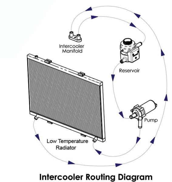
32 separator barb and the remaining supercharger rear inlet barb. The Vacuum routing diagram at the back of the manual can be used as a guide Cut the right hand side supercharger intercooler hose to join the left hand side LTR hose using the provided coupling (hose mender) and two provide spring clamps Connect the left hand side supercharger intercooler hose to the reservoir hose barb using a provided worm gear clamp. It s important to use only the worm gear clamps on the reservoir. The Intercooler plumbing diagram at the back of the manual can be used as a guide Install the provided air tube to the throttle body with the hump hose coupling at the air box and the fl at coupling at the throttle body. It s easier if you slide the throttle body hose completely onto the tube, then pull it back onto the throttle body after the air tube is in place Install the provided accessory drive belt 05/17 Page 32

 in the")


33 (using the routing diagram at the back of the manual as a guide) by springing the tensioner with a 3/8 drive breaker bar or ratchet. (This photo is of an older model but the tensioner location is the same.) 122. Use the existing waterpump bolt to install the provided bracket (highlighted in green) in the location shown with the red arrow. Slide the EVAP solenoid over the bracket, and connect the original hose and plug in the original electrical connections in the the locations shown with the yellow arrows Insert the provided 15A fuse into the fuse holder on the intercooler pump wiring harness and replace the cover Attach the fuse holder and relay to the provided bracket and connect the bracket Connect the bracket shown in the previous 05/17 Page 33


34 step with the fuse holder and relay attached to the left side upper radiator bolt (shown with an arrow). The bracket is silver in this photo for clarity Route the terminal connection for the intercooler pump from the relay just installed under the radiator to the opposite side of the vehicle where the intercooler pump is located. Secure the wire in place using some provided cable ties where shown with the arrows Connect the intercooler harness plug to the terminal at the bottom of the intercooler pump Remove the ring terminal from the red power wire end of the intercooler pump harness using a pair of wire cutters. Strip the insulation from the red wire and crimp on the new larger provided ring terminal connector (shown with the arrow in the photo) Depress the latch clamps on the front side 05/17 Page 34

.")
.")
35 of the fuse center cover and tilt it open Remove the nut shown with the yellow arrow, place the large ring terminal that was connected to the red wire two steps ago on the stud, and tighten the nut back on it. The yellow trigger wire (shown with a red arrow) will be connected to a provided fuse tap in the next step. You will have to cut and strip the yellow trigger wire to prepare it for connection Crimp the supplied fuse tap connector onto the yellow trigger wire (shown here in the person s hand). Use the diagram on the underside of the fuse box lid to locate the F75-Coolant Temp Valve 10A fuse. Remove the F75-Coolant Temp Valve 10A fuse from the fuse box and install it in the lower fuse slot of the provided fuse tap (shown with a red arrow). Install the provided 15A fuse in the upper location of the fuse tap (shown with a blue arrow) Notch the fuse box in the area indicated with the yellow arrow to give clearance for the red fuse tap wire so it will not get pinched when the fuse box is closed. Route the wire through the notch just created, and install the tap into the (F75- Coolant Temp Valve) location where the 10A fuse used to be with the same orientation shown in the photo (as shown with the red arrow) Replace the fuse center cover. 05/17 Page 35


36 134. Connect the black ground wire from the intercooler pump harness to the bolt location shown with the arrow located on the lower left frame member Snap the bottom grille connectors in place and replace the OEM bolts to secure the grille to the fascia with a 10mm wrench Fill the intercooler system using the same coolant mixture recommended by the vehicle manufacturer for your engine coolant system. Once the system has been running, use the air bleed valve on the top of the LTR to remove air from the system Should you want easy access to the LTR 05/17 Page 36

.")


37 bleed valve, test fi t the plastic radiator cover, and use an awl or punch to mark a hole to accommodate the LTR air-bleed valve. Drill a ½ hole at the mark you made Install the radiator cover with the air-bleed access exposed (extended in this image to show location). NOTE: If your kit came with a plug installed, remove the plug and replace with the provided bleed fi tting using Tefl on tape on the threads Connect the battery negative (-) terminal Start the vehicle for fi ve seconds and shut Make sure that you have followed step #2 in this manual to load the proper supercharger calibration to your vehicle s ECM. off. Check for fuel, coolant leaks and supercharger belt alignment. Check radiator and intercooler reservoir levels and top off as necessary After the initial start up, and the engine 05/17 Page 37


.")
38 has come to operating temperature, recheck the coolant level in the engine and intercooler reservoir. Open the bleed valve again to allow any residual air trapped to escape the system. Check all hose connections. Check & bleed charge air cooler reservoir as needed Test drive the vehicle for the fi rst few miles under normal driving conditions. Do not perform any wide open throttle runs. Listen for any noises, vibrations, engine miss fi re or anything that does not seem normal. The supercharger does have a slight whining noise under boost conditions, this is normal After the initial test drive, gradually work the vehicle to wide open throttle runs. Listen for any engine detonation (pinging). If engine detonation is present, let up on the throttle immediately. Most detonation is caused by low octane fuel still in the tank. PREMIUM GASOLINE FUEL MUST BE USED. If you have questions about your vehicles performance, please check with your installation facility. 05/17 Page 38

39 S/C ALT IDLER W/P TENSR. CRANK A/C Belt Routing Diagram 05/17 Page 39


40 NOTE: This vehicle IS NOT compatible with E85 fuel. You can use ONLY premium gasoline fuel 91 octane or better. Ethanol is NOT compatible with the engine after supercharger install. Please enjoy your Magnson Supercharged performance responsibly.
Installation Instructions for: Dodge RAM 5.7 Liter HEMI INTERCOOLED SUPERCHARGER SYSTEM
 Installation Instructions for: 2009-2010 Dodge RAM 5.7 Liter HEMI INTERCOOLED SUPERCHARGER SYSTEM Step-by-step instructions for installing the best in supercharger systems. * PREMIUM GASOLINE FUEL REQUIRED
INTERCOOLED SUPERCHARGER SYSTEM Dodge Challenger 5.7 Liter HEMI
 Installation Instructions for: INTERCOOLED SUPERCHARGER SYSTEM 2009-10 Dodge Challenger 5.7 Liter HEMI Step-by-step instructions for installing the best in supercharger systems. * PREMIUM GASOLINE FUEL
Installation Instructions for: JEEP CHEROKEE 6.1 Liter HEMI INTERCOOLED SUPERCHARGER SYSTEM
 Installation Instructions for: 2006-10 JEEP CHEROKEE 6.1 Liter HEMI INTERCOOLED SUPERCHARGER SYSTEM Step-by-step instructions for installing the best in supercharger systems. * PREMIUM FUEL REQUIRED *
Installation Instructions for: CORVETTE SUPERCHARGER SYSTEM LT4 Z06 CORVETTE
 Installation Instructions for: CORVETTE SUPERCHARGER SYSTEM 2015+ LT4 Z06 CORVETTE Step-by-step instructions for installing the HeartBeat of supercharger systems. * PREMIUM GASOLINE FUEL REQUIRED * ATTENTION!
Jeep Wrangler 3.6L V-6 INTERCOOLED SUPERCHARGER SYSTEM
 Installation Instructions for: 2012 + Jeep Wrangler 3.6L V-6 INTERCOOLED SUPERCHARGER SYSTEM PREMIUM GASOLINE FUEL REQUIRED ATTENTION: Your MAGNUSON SUPERCHARGER kit is sensitive to corrosion! Take care
SUPERCHARGER SYSTEM LT1 Chevrolet Camaro
 HeartBeat Installation Instructions for: SUPERCHARGER SYSTEM 2016-2017 LT1 Chevrolet Camaro NON-INTERCOOLED Step-by-step instructions for installing the best in supercharger systems * PREMIUM GASOLINE
Installation Instructions for: Sierra 5.3/6.2L DI INTERCOOLED SUPERCHARGER SYSTEM
 Installation Instructions for: INTERCOOLED SUPERCHARGER SYSTEM Step-by-step instructions for installing the best in supercharger systems. * PREMIUM GASOLINE FUEL REQUIRED * ATTENTION! Your MAGNUSON SUPERCHARGER
137. Unbolt the fi ve bolts holding the coil brackets to the valve covers using a 10mm wrench Remove the coil brackets for modifi cation.
 137. Unbolt the fi ve bolts holding the coil brackets to the valve covers using a 10mm wrench. 138. Remove the coil brackets for modifi cation. 139. Use a small fl athead screwdriver to unsnap the plastic
INTERCOOLED SUPERCHARGER SYSTEM FORD 5.4L 3V F-150 TRUCK
 Installation Instructions for: INTERCOOLED SUPERCHARGER SYSTEM 2004-2006 FORD 5.4L 3V F-150 TRUCK Step-by-step instructions for installing the best in supercharger systems. 89-89-65-001 Rev C Magnuson
Installation Instructions for: Toyota 4Runner and FJ Cruiser
 Installation Instructions for: 2010-2017 Toyota 4Runner and 2010-2014 FJ Cruiser Step-by-step instructions for installation of the supercharger system. * PREMIUM GASOLINE FUEL REQUIRED * ATTENTION! Your
Installation Instructions for: Sierra 5.3/6.2L DI
 Installation Instructions for: INTERCOOLED SUPERCHARGER SYSTEM Step-by-step instructions for installing the best in supercharger systems. * PREMIUM GASOLINE FUEL REQUIRED * ATTENTION! Your MAGNUSON SUPERCHARGER
FORD MUSTANG 5.0L
 Installation instructions for: INTERCOOLED SUPERCHARGER SYSTEM 2011-2013 FORD MUSTANG 5.0L Step-by-step instructions for installing the best in supercharger systems. * PREMIUM FUEL REQUIRED * ATTENTION!
SMALL BLOCK CHEVROLET SUPERCHARGER SYSTEM
 Installation Instructions for: SMALL BLOCK CHEVROLET SUPERCHARGER SYSTEM Step-by-step instructions for installing the best in supercharger systems. * PREMIUM FUEL REQUIRED * 89-89-57-008-TF Rev B Magnuson
Installation Instructions for: Radix Max. Intercooled Supercharger System GM 6.0L & 6.2L TRUCKS
 Installation Instructions for: Radix Max Intercooled Supercharger System 07-13 GM 6.0L & 6.2L TRUCKS Step-by-step instructions for installing the best in supercharger systems. * PREMIUM GASOLINE FUEL REQUIRED
Installation Instructions for: Radix. INTERCOOLED SUPERCHARGER SYSTEM 2008 Hummer H3-Alpha
 Installation Instructions for: Radix INTERCOOLED SUPERCHARGER SYSTEM 2008 Hummer H3-Alpha Step-by-step instructions for installing the best in supercharger systems. ATTENTION! Your MAGNA CHARGER intercooler
INTERCOOLED SUPERCHARGER SYSTEM Dodge Challenger 6.1 Liter HEMI
 Installation Instructions for: INTERCOOLED SUPERCHARGER SYSTEM 2009+ Dodge Challenger 6.1 Liter HEMI Step-by-step instructions for installing the best in supercharger systems. * PREMIUM FUEL REQUIRED *
INTERCOOLED SUPERCHARGER SYSTEM LS3/L99 Chevrolet Camaro
 HeartBeat Installation Instructions for: INTERCOOLED SUPERCHARGER SYSTEM 2013-2015 LS3/L99 Chevrolet Camaro Step-by-step instructions for installing the best in supercharger systems. * PREMIUM GASOLINE
Installation Instructions for: Radix. Intercooled Supercharger System GM 4.8L & 5.3L SUV S Only
 Installation Instructions for: Radix Intercooled Supercharger System 07-10 GM 4.8L & 5.3L SUV S Only Step-by-step instructions for installing the best in supercharger systems. * PREMIUM FUEL REQUIRED *
Installation Instructions for: Radix Retro. Intercooled Supercharger System GM 4.8L & 5.3L TRUCKS
 Installation Instructions for: Radix Retro Intercooled Supercharger System 07-13 GM 4.8L & 5.3L TRUCKS Step-by-step instructions for installing the best in supercharger systems. * PREMIUM GASOLINE FUEL
INTERCOOLED SUPERCHARGER SYSTEM LS3/L99 Chevrolet Camaro
 HeartBeat Installation Instructions for: INTERCOOLED SUPERCHARGER SYSTEM 2010-2012 LS3/L99 Chevrolet Camaro Step-by-step instructions for installing the best in supercharger systems. ATTENTION! Your MAGNUSON
Installation Instructions for: HOT ROD SUPERCHARGER SYSTEM
 Installation Instructions for: HOT ROD SUPERCHARGER SYSTEM 89-89-57-007 Step-by-step instructions for installing the best in supercharger systems. Magnuson Products Inc 1990 Knoll Drive, Ventura, CA. 93003
Installation Instructions for: TOYOTA 4.5L SUPERCHARGER SYSTEM
 Installation Instructions for: TOYOTA 4.5L SUPERCHARGER SYSTEM 1995-1997 Land Cruiser * PREMIUM FUEL REQUIRED * Magnuson Products LLC 1990 Knoll Drive, Bldg A, Ventura, CA 93003 (805) 642-8833 phone *
Instructions for: Toyota 5.7L Coupler Replacement
 Instructions for: Toyota 5.7L Coupler Replacement * PREMIUM GASOLINE FUEL REQUIRED * ATTENTION! Your MAGNUSON SUPERCHARGER kit is sensitive to corrosion! Use only the vehicle manufacturer recommended coolant
Installation Instructions for: Toyota Tundra 5.7L
 Installation Instructions for: 2009-2015 Toyota Tundra 5.7L -For Flex Fuel Trucks- Step-by-step instructions for installation of the supercharger system. * PREMIUM GASOLINE FUEL REQUIRED* *NOT COMPATIBLE
Edelbrock E-Force Supercharger Part #1538: Dodge 1500 Truck 5.7L V8 HEMI
 Edelbrock E-Force Supercharger Part #1538: 2009-2014 Dodge 1500 Truck 5.7L V8 HEMI 2009-14 Dodge 5.7L Hemi 1500 Truck INTRODUCTION Thank you for purchasing the Edelbrock Supercharger System for the 2009-15
Installation Instructions for: CORVETTE SUPERCHARGER SYSTEM C6 LS3 CORVETTE
 Installation Instructions for: CORVETTE SUPERCHARGER SYSTEM 2008-2013 C6 LS3 CORVETTE Step-by-step instructions for installing the best in supercharger systems. * PREMIUM FUEL REQUIRED * ATTENTION! Your
Installation Instructions for: CORVETTE SUPERCHARGER SYSTEM C7 LT1 CORVETTE
 Installation Instructions for: CORVETTE SUPERCHARGER SYSTEM 2014-2017 C7 LT1 CORVETTE Step-by-step instructions for installing the HeartBeat of supercharger systems. * PREMIUM GASOLINE FUEL REQUIRED *
Procharger Stage II Intercooled Supercharger System (11-14 GT)
") Procharger Stage II Intercooled Supercharger System (11-14 GT) Installation Time: Approximately one day. Installed on 2012 Mustang GT 5.0/Manual Required Tools 3/8 Socket Set (Standard and Metric) 1/2
Procharger Stage II Intercooled Supercharger System (11-14 GT) Installation Time: Approximately one day. Installed on 2012 Mustang GT 5.0/Manual Required Tools 3/8 Socket Set (Standard and Metric) 1/2
Installation Instructions for: Radix Retro. Intercooled Supercharger System GM 4.8L & 5.3L TRUCKS
 Installation Instructions for: Radix Retro Intercooled Supercharger System 07-10 GM 4.8L & 5.3L TRUCKS Step-by-step instructions for installing the best in supercharger systems. * PREMIUM FUEL REQUIRED
Installation Instructions for: Radix Retro. Intercooled Supercharger System GM 4.8L & 5.3L SUV s
 Installation Instructions for: Radix Retro Intercooled Supercharger System 07-13 GM 4.8L & 5.3L SUV s Step-by-step instructions for installing the best in supercharger systems. * PREMIUM GASOLINE FUEL
Installation Instructions for: Radix. INTERCOOLED SUPERCHARGER SYSTEM L Chevrolet Trailblazer SS
 Installation Instructions for: Radix INTERCOOLED SUPERCHARGER SYSTEM 2006-2007 6.0L Chevrolet Trailblazer SS Step-by-step instructions for installing the best in supercharger systems. ATTENTION! Your MAGNA
Installation Instructions for: CORVETTE SUPERCHARGER SYSTEM 1997 TO 2004 C5 & Z06 CORVETTE
 Installation Instructions for: CORVETTE SUPERCHARGER SYSTEM 1997 TO 2004 C5 & Z06 CORVETTE Step-by-step instructions for installing the best in supercharger systems. * PREMIUM FUEL REQUIRED * ATTENTION!
INTERCOOLED SUPERCHARGER SYSTEM 2004 PONTIAC GTO
 Installation Instructions for: INTERCOOLED SUPERCHARGER SYSTEM 2004 PONTIAC GTO 89-89-60-013 Rev. F Step-by-step instructions for installing the best in supercharger systems. Magnuson Products Inc 1990
Installation Instructions for: Toyota Tacoma 4.0L
 Installation Instructions for: 2005-2015 Toyota Tacoma 4.0L Step-by-step instructions for installation of the supercharger system. * PREMIUM GASOLINE FUEL REQUIRED * ATTENTION! Your MAGNUSON SUPERCHARGER
INTERCOOLED SUPERCHARGER SYSTEM PONTIAC GTO LS2
 Installation Instructions for: INTERCOOLED SUPERCHARGER SYSTEM 2005-2006 PONTIAC GTO LS2 Step-by-step instructions for installing the best in supercharger systems. Magnuson Products Inc 1990 Knoll Drive,
Intercooled Supercharger System , 2007 Classic GM Trucks, 4.8L, 5.3L & 6.0L
 Installation Instructions for: Radix Retro Intercooled Supercharger System 2003-2006, 2007 Classic GM Trucks, 4.8L, 5.3L & 6.0L * PREMIUM GASOLINE FUEL REQUIRED * Step-by-step instructions for installing
SLP Camaro ZL1 STAGE 3 (650 HP)
") SLP - 2012 Camaro ZL1 STAGE 3 (650 HP) PART #26002 PACKING LIST Before installation, use this check list to make sure all necessary parts have been included. ITEM QTY CHECK PART NUMBER DESCRIPTION 1. 1
SLP - 2012 Camaro ZL1 STAGE 3 (650 HP) PART #26002 PACKING LIST Before installation, use this check list to make sure all necessary parts have been included. ITEM QTY CHECK PART NUMBER DESCRIPTION 1. 1
Slingshot Rotrex Supercharger Kit
 Slingshot Rotrex Supercharger Kit This supercharger kit improves on the Slingshot by forcing more dense air into the engine and creating more power. Installation time of the supercharger depends on you
Edelbrock E-Force Supercharger JEEP WRANGLER JK 3.6L V6 Part #1527 and 15270
 Edelbrock E-Force Supercharger 2012-14 JEEP WRANGLER JK 3.6L V6 Part #1527 and 15270 INTRODUCTION Thank you for purchasing the Edelbrock Supercharger System for the Jeep Wrangler with 3.6L V6 Pentastar.
Installation Instructions for: TOYOTA 3.4L SUPERCHARGER SYSTEM
 Installation Instructions for: TOYOTA 3.4L SUPERCHARGER SYSTEM 1996-2002 4Runner 1997-1998 T100 1997-2004 Tacoma 2000-2003 Tundra * PREMIUM FUEL REQUIRED * Magnuson Products LLC 1990 Knoll Drive, Bldg
Weistec M113K Supercharger System Installation Guide
 Weistec M113K Supercharger System Installation Guide WARNING! DO NOT HAVE YOUR ECU REPROGRAMMED ANYWHERE BUT AT WEISTEC FOR THIS SUPERCHARGER. THE AMG 55 USES AN ELECTRONIC THROTTLE CONTROL (ETC), WHICH
Installation Instructions for: Radix. Intercooled Supercharger System Avalanche 1500, Tahoe 1500, Suburban 1500 & Yukon 1500
 Installation Instructions for: Radix Intercooled Supercharger System 2003-2006 Avalanche 1500, Tahoe 1500, Suburban 1500 & Yukon 1500 PREMIUM GASOLINE FUEL REQUIRED Step-by-step instructions for installing
Supercharger System Chevrolet Silverado1500 & GMC Sierra 1500 Light Duty Sport Trucks
 Installation Instructions for: Radix-NI Supercharger System 2003-2006 Chevrolet Silverado1500 & GMC Sierra 1500 Light Duty Sport Trucks 89-89-59-003 Rev C Step-by-step instructions for installing the best
Installation Instructions for: Radix. Intercooled Supercharger System
 Installation Instructions for: Radix Intercooled Supercharger System 2003-2006, 2007 Classic Chevrolet Silverado & GMC Sierra Trucks Suburban 2500, Yukon XL 2500 & Avalanche 2500 * PREMIUM GASOLINE FUEL
Edelbrock E-Force Supercharger Dodge/Chrysler 5.7L and 6.4L HEMI Part #1534, 1535, and 15350
 Edelbrock E-Force Supercharger 2011-2013 Dodge/Chrysler 5.7L and 6.4L HEMI Part #1534, 1535, 15340 and 15350 PLEASE COMPLETE THIS PROCEDURE PRIOR to starting the installation of your E-Force supercharger
INTERCOOLED SUPERCHARGER SYSTEM Dodge Challenger 6.4 Liter HEMI
 Installation Instructions for: INTERCOOLED SUPERCHARGER SYSTEM 2011+ Dodge Challenger 6.4 Liter HEMI Step-by-step instructions for installing the best in supercharger systems. * PREMIUM FUEL REQUIRED *
Edelbrock E-Force Supercharger. Part #1538: Dodge 1500 Truck 5.7L V8 HEMI
 Edelbrock E-Force Supercharger : 2009-2014 Dodge 1500 Truck 5.7L V8 HEMI 2009-14 Dodge 5.7L Hemi 1500 Truck INTRODUCTION Thank you for purchasing the Edelbrock Supercharger System for the 2009-15 Dodge
Edelbrock E-Force Supercharger. For: Dodge/RAM 1500 Truck 5.7L V8 HEMI PN: 1538, 15380, 15175
 Edelbrock E-Force Supercharger For: 2009-2017 Dodge/RAM 1500 Truck 5.7L V8 HEMI PN: 1538, 15380, 15175 WARNING! The supercharger bypass valve is factory installed and adjusted intended to be vacuum operated
Always wear safety glasses when working on your vehicle.
 90-93 MAZDA MIATA SUPERCHARGER KIT The KraftWerks 90-93 Mazda Miata Supercharger Kit was designed for easy installation. Competent mechanics with the appropriate tools will find the process to be relatively
Huron Speed Products Twin Turbo Install Gen 2 CTS-V (09-15)
") Huron Speed Products Twin Turbo Install Gen 2 CTS-V (09-15) The following install guide is simply that, a guide to help you with installation. It is by no means the exact method to perform installation,
Huron Speed Products Twin Turbo Install Gen 2 CTS-V (09-15) The following install guide is simply that, a guide to help you with installation. It is by no means the exact method to perform installation,
2006 Honda Civic SI Supercharger Kit Installation Instruction Kit #
 2006 Honda Civic SI Supercharger Kit Installation Instruction Kit #350-091 3239 MONIER CIRCLE, STE.5 RANCHO CORDOVA, CA 95742 916.635.4550 FAX 916.635.4632 www.ct-engineering.com INS-157 VERSION: 3.25.2009
LChevrolet Camaro Supercharger Kit
 PART #92000A Important Notes: 2010-2013 6.2LChevrolet Camaro Supercharger Kit The use of fuel additives (ie. octane boosters) is not recommended. There is a possibility that these chemicals can damage
Installation Instructions for: Audi S4 V6 (B8, B8.5) & S5 (B8.5)
 & S5 (B8.5)") Installation Instructions for: Audi S4 V6 (B8, B8.5) & S5 (B8.5) Step-by-step instructions for installation of the supercharger system. * PREMIUM GASOLINE FUEL REQUIRED * ATTENTION! Your MAGNUSON SUPERCHARGER
Installation Instructions for: Audi S4 V6 (B8, B8.5) & S5 (B8.5) Step-by-step instructions for installation of the supercharger system. * PREMIUM GASOLINE FUEL REQUIRED * ATTENTION! Your MAGNUSON SUPERCHARGER
ENGINE DEVELOPMENT INC.
 2003 Ford Expedition 4.6L& 5.4L We encourage you to read this manual thoroughly before you begin work, and perform the following: 1. A quick parts check to make certain your kit is complete. If you discover
Installation Instructions for: Toyota Tundra 5.7L -Not for Flex Fuel Trucks-
 Installation Instructions for: 2007-2017 Toyota Tundra 5.7L -Not for Flex Fuel Trucks- Step-by-step instructions for installation of the supercharger system. * PREMIUM GASOLINE FUEL REQUIRED * ATTENTION!
Installation Instructions for Lingenfelter GM 2500 Suburban & Yukon XL Auxiliary Fan System (with AC clutch controlled fan output)
") Installation Instructions for Lingenfelter 2007-2013 GM 2500 Suburban & Yukon XL Auxiliary Fan System (with AC clutch controlled fan output) PN L300080607 Revision - 1.1 Lingenfelter Performance Engineering
Installation Instructions for Lingenfelter 2007-2013 GM 2500 Suburban & Yukon XL Auxiliary Fan System (with AC clutch controlled fan output) PN L300080607 Revision - 1.1 Lingenfelter Performance Engineering
Edelbrock E-Force Supercharger JEEP WRANGLER JK 3.6L V6 Part #1527, 1528, and 15270
 Edelbrock E-Force Supercharger 2012-16 JEEP WRANGLER JK 3.6L V6 Part #1527, 1528, 15282 and 15270 WARNING! The supercharger bypass valve is factory installed and adjusted intended to be vacuum operated
Edelbrock E-Force Supercharger Dodge 1500 Truck 5.7L V8 HEMI Part #1538
 Edelbrock E-Force Supercharger 2009-2014 Dodge 1500 Truck 5.7L V8 HEMI INTRODUCTION Thank you for purchasing the Edelbrock Supercharger System for the 2009-14 Dodge 1500 Truck with 5.7L V8 Hemi. The utilizes
Edelbrock E-Force Supercharger 2015 Ford Mustang 5.0L Part # s: 1586 & 15860
 Edelbrock E-Force Supercharger Part # s: 1586 & 15860 Thank you for purchasing the Edelbrock E-Force Supercharger System for the. The Edelbrock E-Force Supercharger System utilizes Eaton s Gen VI 2300
Edelbrock Victor II Intake Manifold. For Chrysler 5.7L (Eagle), 6.1L and 6.4L Gen III HEMI Engines Part #7179
, 6.1L and 6.4L Gen III HEMI Engines Part #7179") For Chrysler 5.7L (Eagle), 6.1L and 6.4L Gen III HEMI Engines PLEASE study these instructions carefully before beginning this installation. You should be familiar with and comfortable working on your
For Chrysler 5.7L (Eagle), 6.1L and 6.4L Gen III HEMI Engines PLEASE study these instructions carefully before beginning this installation. You should be familiar with and comfortable working on your
Huron Speed Products Twin Turbo Install Gen 2 CTS-V (09-15)
") Huron Speed Products Twin Turbo Install Gen 2 CTS-V (09-15) 1 2 Remove two bolts in trunk cover with 8mm socket. Pull up on cover to remove. Unscrew net tie down on side cover where battery is located
Huron Speed Products Twin Turbo Install Gen 2 CTS-V (09-15) 1 2 Remove two bolts in trunk cover with 8mm socket. Pull up on cover to remove. Unscrew net tie down on side cover where battery is located
Edelbrock Hemi Supercharger Part #1530, 1531, 1532, 1533, 1536 & 1537
 Edelbrock Hemi Supercharger INTRODUCTION Thank you for purchasing the Edelbrock Hemi Supercharger System for various Chrysler/Dodge vehicles. The Edelbrock E-Force Supercharger System for the 2005 to 2010
Edelbrock Victor II Intake Manifold. For Chrysler 5.7L (Eagle) and 6.1L Gen III HEMI Engines Part #7179
 and 6.1L Gen III HEMI Engines Part #7179") For Chrysler 5.7L (Eagle) and 6.1L Gen III HEMI Engines PLEASE study these instructions carefully before beginning this installation. You should be familiar with and comfortable working on your vehicle.
For Chrysler 5.7L (Eagle) and 6.1L Gen III HEMI Engines PLEASE study these instructions carefully before beginning this installation. You should be familiar with and comfortable working on your vehicle.
2015 Corvette Supercharger System Instructions
 2015 Corvette Supercharger System Instructions These instructions are meant to serve as a guide to the installation of the ECS 2015 Corvette Supercharging system. Please be sure to use all safety equipment
Radix. Installation Instructions for: Intercooled Supercharger System Chevrolet Silverado & GMC Sierra Trucks Suburban 2500 & Yukon XL 2500
 Installation Instructions for: Radix Intercooled Supercharger System 1999-2002 Chevrolet Silverado & GMC Sierra Trucks Suburban 2500 & Yukon XL 2500 * PREMIUM GASOLINE FUEL REQUIRED * ATTENTION! Your MAGNUSON
Installation Instructions for: Radix. Intercooled Supercharger System Avalanche 1500, Tahoe 1500, Subruban 1500 & Yukon 1500
 Installation Instructions for: Radix Intercooled Supercharger System 2003-2006 Avalanche 1500, Tahoe 1500, Subruban 1500 & Yukon 1500 89-89-60-003 Rev I Step-by-step instructions for installing the best
IAG Street Series Air / Oil Separator (AOS) For 2017 WRX
 For 2017 WRX") P IAG Street Series Air / Oil Separator (AOS) For 2017 WRX Part# IAG-ENG-7152 Tools Required: Ratchet, torque wrench, extensions, needle nose pliers, hose cutter, snips/scissors, flathead screwdriver,
P IAG Street Series Air / Oil Separator (AOS) For 2017 WRX Part# IAG-ENG-7152 Tools Required: Ratchet, torque wrench, extensions, needle nose pliers, hose cutter, snips/scissors, flathead screwdriver,
Edelbrock E-Force Supercharger Ford Mustang 5.0L Part # s: 1586, 15860, 15865, & (P/N for reference only)
") Edelbrock E-Force Supercharger Part # s: 1586, 15860, 15865, 158650 & 15863 (P/N 15863 for reference only) WARNING! The supercharger bypass valve is factory installed and adjusted intended to be vacuum
Edelbrock E-Force Supercharger Part # s: 1586, 15860, 15865, 158650 & 15863 (P/N 15863 for reference only) WARNING! The supercharger bypass valve is factory installed and adjusted intended to be vacuum
Installation Instructions for: INTERCOOLED SUPERCHARGER SYSTEM CADILLAC CTS-V
 Installation Instructions for: INTERCOOLED SUPERCHARGER SYSTEM 2004-2005 CADILLAC CTS-V Rev. A Step-by-step instructions for installing the best in supercharger systems. Magnuson Products Inc 3172 Bunsen
Edelbrock 5.0L Mustang GT Supercharger Part #1588 & 1589
 Edelbrock 5.0L Mustang GT Supercharger Part #1588 & 1589 INTRODUCTION Edelbrock 5.0L Ford Supercharger System Thank you for purchasing the Edelbrock 5.0L Ford Supercharger System for the Mustang GT. The
Edelbrock E-Force Supercharger Complete Competition Ford Mustang 5.0L Part # s: 15896
 Edelbrock E-Force Supercharger Complete Competition Part # s: 15896 Introduction Thank you for purchasing the Edelbrock Complete Competition Supercharger System for the 2011-2013 5.0L Ford Mustang GT.
Installation Instructions for Lingenfelter GM 2500 Suburban & Yukon XL Auxiliary Fan System (with ECM controlled fan output)
") Installation Instructions for Lingenfelter 2007-2013 GM 2500 Suburban & Yukon XL Auxiliary Fan System (with ECM controlled fan output) PN L300090607 Revision - 1.1 Lingenfelter Performance Engineering
Installation Instructions for Lingenfelter 2007-2013 GM 2500 Suburban & Yukon XL Auxiliary Fan System (with ECM controlled fan output) PN L300090607 Revision - 1.1 Lingenfelter Performance Engineering
IAG Street Series Air / Oil Separator (AOS) For WRX
 For WRX") P IAG Street Series Air / Oil Separator (AOS) For 2015-16 WRX Part# IAG-ENG-7152 Tools Required: Ratchet, torque wrench, extensions, needle nose pliers, hose cutter, snips/scissors, flat head screw driver,
P IAG Street Series Air / Oil Separator (AOS) For 2015-16 WRX Part# IAG-ENG-7152 Tools Required: Ratchet, torque wrench, extensions, needle nose pliers, hose cutter, snips/scissors, flat head screw driver,
Installation Instructions for: Toyota Tundra 5.7L -Not for Flex Fuel Trucks-
 Installation Instructions for: 2007-2015 Toyota Tundra 5.7L -Not for Flex Fuel Trucks- Step-by-step instructions for installation of the supercharger system. * PREMIUM GASOLINE FUEL REQUIRED * ATTENTION!
Edelbrock E-Force Supercharger Stage II System Ford Mustang 5.0L Part # s: 15896
 Edelbrock E-Force Supercharger Part # s: 15896 WARNING! The supercharger bypass valve is factory installed and adjusted intended to be vacuum operated only. DO NOT move the solenoid actuator lever by
Phone Fax
 Directions for Installation of ECS Paxton Supercharger Kit Disconnect battery Remove stock serpentine belt Remove stock belt tensioner, save the 2 bolts for later use on supercharger bracket Remove alternator
Edelbrock E-Force Supercharger Ford Mustang 5.0L Stage II Part # s: 15862, , 15864,
 Edelbrock E-Force Supercharger Part # s: 15862, 158620, 15864, 158640 WARNING! The supercharger bypass valve is factory installed and adjusted intended to be vacuum operated only. DO NOT move the solenoid
INSTALLATION INSTRUCTIONS STILLEN SUPERCHARGER KIT Nissan 350Z P/N &
 Equipment needed: 1. Assorted sockets and wrenches 2. +,- Screwdrivers 3. Assorted pliers/ Clamps 4. Wire cutting/crimping tools 5. Thread locking compound (blue) 6. Solder gun/ shrink wrap (optional)
Edelbrock E-Force Supercharger Dodge/Chrysler 5.7L and 6.4L HEMI Part #1534, 1535, and 15350
 Edelbrock E-Force Supercharger 2011-2013 Dodge/Chrysler 5.7L and 6.4L HEMI, 15340 and 15350 PLEASE COMPLETE THIS PROCEDURE PRIOR to starting the installation of your E-Force supercharger system. This
3.4L V6 SUPERCHARGER 7 TH INJECTOR KIT
 Part Number: 00602-17620-260 00602-17620-261 00602-17620-263 00602-17620-264 00602-17620-274 00602-17620-275 00602-17620-276 Section I Installation Preparation Kit Contents Item # Quantity Reqd. Description
Edelbrock E-Force Supercharger L HEMI / L HEMI Part #1530, 1531, 1532, 1533, 1536 & 1537
 Edelbrock E-Force Supercharger 2005-10 6.1L HEMI / 2006-10 5.7L HEMI PLEASE COMPLETE THIS PROCEDURE PRIOR to starting the installation of your E-Force supercharger system. This will allow our calibration
05-08 GT. Hellion Power Systems Mustang Kit Instructions
 Hellion Power Systems 05-08 Mustang Kit Instructions 1. Disconnect Battery 2. Drain Radiator, keep fluid for re-installation. 3. Remove air box and inlethoses. 6. Next, underneath, punch oil pan for turbo
IAG Competition Series Air / Oil Separator (AOS) For WRX
 For WRX") P IAG Competition Series Air / Oil Separator (AOS) For 2015-16 WRX Part# IAG-ENG-7252 Tools Required: Ratchet, torque wrench, extensions, needle nose pliers, hose cutter, snips/scissors, flat head screw
P IAG Competition Series Air / Oil Separator (AOS) For 2015-16 WRX Part# IAG-ENG-7252 Tools Required: Ratchet, torque wrench, extensions, needle nose pliers, hose cutter, snips/scissors, flat head screw
INTERCOOLED SUPERCHARGER SYSTEM CADILLAC CTS-V
 Installation Instructions for: INTERCOOLED SUPERCHARGER SYSTEM 2004-2005 CADILLAC CTS-V 89-89-60-015 Rev C Step-by-step instructions for installing the best in supercharger systems. Magnuson Products Inc
Z06 Corvette Lingenfelter High Flow Air Intake
 2006-2007 Z06 Corvette Lingenfelter High Flow Air Intake LN4233 1557 Winchester Road Decatur, Indiana 46733 260 724 2552 phone 260 724 8761 fax www.lingenfelter.com Parts List # Part number Description
SHELBY GT500
 2007-2009 SHELBY GT500 Removal of Factory Unit WARNING: 1. Radiator fluid must be handled properly. Please observe local ordinances with regards to handling and disposal. 2. Allow vehicle and components
#TL T EA888 GEN 3 FUELING SYSTEM/ INSTALLATION INSTRUCTIONS
 #TL100069 2.0T EA888 GEN 3 FUELING SYSTEM/ INSTALLATION INSTRUCTIONS Notes: These instructions were written for a North American specification MkVII GTI. Other models, like the Golf R, are similar. When
Edelbrock LS2 Corvette Supercharger Part #1593, 1594 & 1595
 Edelbrock LS2 Corvette Supercharger INTRODUCTION Thank you for purchasing the Edelbrock 6.0L GM Supercharger System for the Chevy Corvette. The Edelbrock E-Force Supercharger System for the 2005 to 2007
INTERCOOLED SUPERCHARGER SYSTEM PONTIAC G8 GT (6.0L)
") Installation Instructions for: INTERCOOLED SUPERCHARGER SYSTEM 2008-2009 PONTIAC G8 GT (6.0L) Step-by-step instructions for installing the best in supercharger systems. * PREMIUM FUEL REQUIRED * ATTENTION!
Installation Instructions for: INTERCOOLED SUPERCHARGER SYSTEM 2008-2009 PONTIAC G8 GT (6.0L) Step-by-step instructions for installing the best in supercharger systems. * PREMIUM FUEL REQUIRED * ATTENTION!
INSTALLATION INSTRUCTIONS
 N-MT13-1 & N-MT13-2 COLD AIR INTAKE KIT INSTALLATION INSTRUCTIONS MUSTANG GT 2015-up PARTS INCLUDED Part Number Descrip on Qty 9-SA-INTAKE-100 Intake Assembly 1 9-SA-HEATSHIELD-100 Heatshield Assembly
WARNING: ALWAYS relieve fuel pressure before disconnecting any fuel related component. DO NOT allow fuel to contact engine or electrical components.
 4.0L V8 - VINS [K,U] Selected Block 1990 Lexus LS 400 For Lextreme Powertrain 2020 S. Hacienda Blvd. # D Hacienda Heights California 91745 Copyright 1998 Mitchell Repair Information Company, LLC Friday,
 Special Tools Needed: DrVanos.com Stage I Installation Instructions Camshaft locking tool TDC Crank pin Sprocket turning tool Tool rental is available with the purchase of a vanos kit *See website for
DrVanos.com Stage II Installation Instructions. Tool rental is available with the purchase of a vanos kit *See website for more info*
 DrVanos.com Stage II Installation Instructions Special Tools Needed: Camshaft locking tool TDC Crank pin Sprocket turning tool Tool rental is available with the purchase of a vanos kit *See website for
ENGINE ASSEMBLY STOCK TO 250 HP
 GM SPORT COMPACT Performance Build Book 25 ENGINE ASSEMBLY STOCK TO 250 HP Fig. 3 The stock ECOTEC engine has proven reliable to 250 hp.(fig. 3) Performance upgrades are available from GM Performance Parts
Edelbrock E-Force Supercharger , GM Trucks
 Edelbrock E-Force Supercharger 2007-12, GM Trucks Part # 1578-2007-12, 4.8/5.3L Silverado and Sierra Part # 1579-2007-12, 6.0/6.2L Silverado and Sierra E-MAIL EDELBROCK YOUR STOCK VEHICLE CALIBRATION
Edelbrock LS3 Corvette Supercharger Part #1590, 1591 & 1592
 Edelbrock LS3 Corvette Supercharger Part #1590, 1591 & 1592 INTRODUCTION Thank you for purchasing the Edelbrock 6.2L GM Superchager System for the Chevy Corvette. The Edelbrock E-Force Supercharger System
WARNING: IF YOU ARE NOT EXPERIENCED IN THE AREA OF AUTOMOTIVE MECHANICS WE STRONGLY URGE THAT YOU REFER THIS INSTALLATION TO YOUR MECHANIC.
 INSTALLATION INSTRUCTIONS STILLEN SUPERCHARGER KIT 2003+ Infiniti G35 Materials supplied: See attached list Equipment needed: 1. Assorted sockets and wrenches 2. +,- Screwdrivers 3. Assorted pliers/ Clamps
M-9424-M50CJ INTAKE MANIFOLD INSTALLATION INSTRUCTIONS
 Please visit www.fordracingparts.com for the most current instruction information!!! PLEASE READ ALL OF THE FOLLOWING INSTRUCTIONS CAREFULLY PRIOR TO INSTALLATION. AT ANY TIME YOU DO NOT UNDERSTAND THE
4. Remove (4) 10mm and (1) 7mm bolt that holds fascia at front corners, on each side
 10mm and (1) 7mm bolt that holds fascia at front corners, on each side") 2010 Camaro LS3 1. Disconnect battery ground 2. Remove front wheels 3. Remove (5) push pins and (5) #20 torx screws on inner front wheel well liners and remove liners on each side 4. Remove (4) 10mm and
2010 Camaro LS3 1. Disconnect battery ground 2. Remove front wheels 3. Remove (5) push pins and (5) #20 torx screws on inner front wheel well liners and remove liners on each side 4. Remove (4) 10mm and
MAZDASPEED3 Intercooler Instructions
 MAZDASPEED3 Intercooler Instructions Congratulations on your purchase of the COBB Tuning Front Mount Intercooler System for your 2007-2009 Mazdaspeed3. The following instructions should assist you through