cgm.3 system Fully SF6 gas insulated medium voltage switchgear up to 40.5 kv in accordance with IEC Standards
|
|
|
- Augustus Haynes
- 5 years ago
- Views:
Transcription


1 Fully SF6 gas insulated medium voltage switchgear up to 40.5 kv in accordance with IEC Standards General instructions IG-136-EN, version 10; 23/06/2016
2 CAUTION! When medium-voltage equipment is operating, certain components are live, other parts may be in movement and some may reach high temperatures. Therefore, the use of this equipment poses electrical, mechanical and thermal risks. In order to ensure an acceptable level of protection for people and property, and in compliance with applicable environmental recommendations, Ormazabal designs and manufactures its products according to the principle of integrated safety, based on the following criteria: Elimination of hazards wherever possible. Where elimination of hazards is neither technically nor economically feasible, appropriate protection functions are incorporated in the equipment. Communication about remaining risks to facilitate the design of operating procedures which prevent such risks, training for the personnel in charge of the equipment, and the use of suitable personal protective equipment. Use of recyclable materials and establishment of procedures for the disposal of equipment and components so that once the end of their service lives is reached, they are duly processed in accordance, as far as possible, with the environmental restrictions established by the competent authorities. Consequently, the equipment to which the present manual refers complies with the requirements of section 11.2 of Standard IEC It must therefore only be operated by appropriately qualified and supervised personnel, in accordance with the requirements of standard EN on the safety of electrical installations and standard EN on activities in or near electrical installations. Personnel must be fully familiar with the instructions and warnings contained in this manual and in other recommendations of a more general nature which are applicable to the situation according to current legislation [1]. The above must be carefully observed, as the correct and safe operation of this equipment depends not only on its design but also on general circumstances which are in general beyond the control and responsibility of the manufacturer. More specifically: The equipment must be handled and transported appropriately from the factory to the place of installation. All intermediate storage should occur in conditions which do not alter or damage the characteristics of the equipment or its essential components. Service conditions must be compatible with the equipment rating. The equipment must be operated strictly in accordance with the instructions given in the manual, and the applicable operating and safety principles must be clearly understood. Maintenance should be performed properly, taking into account the actual service and environmental conditions in the place of installation. The manufacturer declines all liability for any significant indirect damages resulting from violation of the guarantee, under any jurisdiction, including loss of income, stoppages and costs resulting from repair or replacement of parts. Warranty The manufacturer guarantees this product against any defect in materials and operation during the contractual period. If defects are detected, the manufacturer may opt either to repair or replace the equipment. Improper handling of this equipment and its repair by the user shall constitute a violation of the guarantee. Registered trademarks and copyrights All registered trademarks cited in this document are the property of their respective owners. The intellectual property of this manual belongs to Ormazabal. [1] For example, in Spain the Regulation on technical conditions and guarantees for safety in high-voltage electrical installations Royal Decree 337/2014 is obligatory. In view of the constant evolution in standards and design, the characteristics of the elements contained in this manual are subject to change without prior notice. These characteristics, as well as the availability of components, are subject to confirmation by Ormazabal.
3 General instructions 3 Contents 1 General description Models Standards applied Main components Gas tank Driving mechanism compartment Base Name plate Characteristics table Dimensions and weights Operating conditions Handling and transport Lifting means Storage Installation Unpacking the equipment Location of accessories during transport Minimum installation distances Recommended cable connection trench Cubicles with internal arc in gas tank up to 20 ka s Cubicles with classification of internal arc IAC up to 25 ka - 1 s Fastening to the floor Fastening to the floor on profile Fastening to the floor by anchoring Connecting the cubicles Earthing the switchgear Cable connections Horizontal front connection Cable connection in fuse protection function 1400 mm high Assembly and connection of measuring transformers in cgm.3-m... 33
4 4 General instructions 5 Recommended sequence of operations Checking the gas pressure Voltage presence indicator Phase balance check Feeder function Mimic diagram Driving levers Opening operation from earthing position Switch closing operation from the disconnected position Opening operation from closed position Earthing operation from the disconnected position Cable test Busbar switch function Mimic diagram Driving lever Switch closing operation from the disconnected position Opening operation from closed position Busbar switch function with earth connection Mimic diagram Driving lever Opening operation from earthing position Connection of the switch-disconnector from the disconnected position Opening operation from closed position Earthing operation from open position Busbar rise function with earth connection Mimic diagram Driving levers Earthing switch disconnection Earthing switch connection Fuse protection function Mimic diagram Driving lever Opening operation from earthing position Spring charge operation and closing of the switch - disconnector from disconnected position Opening operation from the switch-disconnector closed position Earthing operation from the open position Fuse replacement sequence Selection of recommended fuses...57
5 General instructions Circuit-breaker function with AV / RAV driving mechanism Mimic diagram Spring charge and driving levers Opening operation from earthing position Closing operation from open position Opening operation from closed position Earthing Operation from the open position Safety elements Acoustic earthing prevention alarm Interlocks Locking with a padlock Locking with a lock Maintenance Voltage presence indicator test Acoustic earthing prevention alarm test Specific maintenance for the cgm.3-v cubicle Spares and accessories Environmental information... 71
6 6 General description General Instructions 1 General description The by Ormazabal, designed following the requirements indicated by regulations of the International Electrotechnical Commission (IEC), is made up of different unifunctional and multifunctional switchgear models, with full SF 6 gas insulation, which can be used to configure different secondary distribution configurations in medium voltage up to 40.5 kv [1]. 1.1 Models Unifunctional switchgear Function cgm.3-l cgm.3-s cgm.3-s-pt cgm.3-p cgm.3-v cgm.3-rb cgm.3-rc / -r2c cgm.3-m Feeder Busbar switch Busbar switch with earth connection on the right (-ptd) or on the left (-pti) Fuse protection Vacuum circuit-breaker Busbar rise Cable/double cable rise Metering Multifunctional switchgear cgm.3-2lp cgm.3-2lv Functions 2 feeder functions and 1 fuse protection 2 feeder functions and 1 vacuum circuit-breaker [1] Further information at
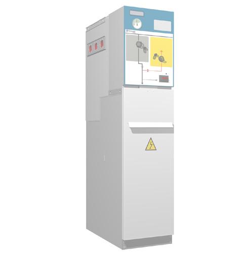
7 General Instructions General description Standards applied Standard IEC IEC IEC IEC IEC IEC IEC / IEC IEC IEC Description Common specifications for high-voltage switchgear and controlgear standards. High-voltage alternating current circuit-breakers. Alternating current disconnectors and earthing switches. High-voltage switches for rated voltages above 1 kv up to and including 52 kv. Alternating current switch-fuse combinations. Alternating current metal-enclosed switchgear and controlgear for rated voltages above 1 kv and up to and including 52 kv. Voltage presence indicating systems. Protection grades for enclosures. Current-limiting fuses. 1.3 Main components 1. Gas tank 1.1. Side connection female bushings 2. Driving mechanism area 2.1.Name plate 2.2.Operating sequence plate 2.3. Driving shafts (see mimic diagram of each model) ekor.vpis / ekor.ivds* Voltage presence detection unit 2.5. ekor.sas* acoustic earthing prevention alarm unit. 3. Base 3.1 Cable compartment access cover 3.2 Medium-voltage cable fastening support 3.3.Gas relief compartment 3.4.Earth collector 3.5 Front cable connection bushings * Optional elements. Figure 1.1 Main elements of cgm.3 cubicles
8 8 General description General Instructions Gas tank Sealed compartment which houses the busbar and the switching and breaking elements, where the insulating medium is SF 6. Each gas tank has a pressure relief device to facilitate gas relief in the event of internal arc. Thanks to the hermetically-sealed nature of the gas tank containing all the medium voltage elements, the equipment is expected to have a minimum service life of 30 years, without replenishing the gas, in accordance with Standard IEC Figure 1.2 Gas tank for cgm.3-l Driving mechanism compartment This is the compartment in which the switch-disconnector, earthing switch or circuit-breaker is driven, depending on the type of function. The mimic diagram for the main medium voltage circuit is displayed on the cover of this compartment. The mimic diagram includes all the position indicators for the driving elements. The has, in line with the cubicle model, the following types of driving mechanism: B Tilting l, s, s-pt, rb-pt, v, 2lp, 2lv BM Motorised tilting l, s, s-pt, 2lp, 2lv BR-A Accumulation of energy with latch p, 2lp BR-AM Accumulation of energy with motorised latch l, p, 2lp AV Circuit-breaker without reclosing v, 2lv AMV Motorised circuit-breaker without reclosing v, 2lv RAV Circuit-breaker with reclosing option v, 2lv RAMV Motorised circuit-breaker with reclosing option v, 2lv These elements are operated independently, i.e., their actuation speed does not depend on the speed of the manual operation. The B, BM, BR, AR and BR-AM driving mechanisms can be replaced by upgrading in any of the three possible positions (closed opened earth). Whilst the driving mechanism is withdrawn, these positions of the switch can be blocked using a coupling device, whether in service or not.
9 General Instructions General description Base Made up of the cable compartment and the gas relief compartment: Cable compartment This is located in the lower front section of the cubicle and has a cover interlocked with the earthing switch, thus allowing front access to the medium voltage cables. As standard, designed to contain up to: Two shielded screw-in terminals (reduced) per phase or one terminal (reduced) plus surge arrester (reduced) with space for the corresponding incoming power cables. Cable ties for the power cables. Earthing bars. As an option: Two symmetric terminals or symmetric terminal plus symmetric surge arrester. Metallic voltage transformers. Figure 1.3 Cable compartment Gas relief compartment The by Ormazabal is designed and constructed to withstand at least the thermal and dynamic effects of an arc of 16 ka for 0.5 seconds should a defect result in an internal arc in the gas compartment. The system conducts the gases generated in a fully controlled manner to avoid any possible injury to people in the equipment operation area. Optionally, a chimney can be positioned in the rear of the cubicle to redirect the gases to the top section. Please check with Ormazabal.
10 10 General description General Instructions Name plate Every unit includes a name plate, with some of the following data: Figure 1.4 Example of name plate Name plate Nº Cubicle serial number (*) Type Designation Standard Name U r U p U d f r Cubicle system Ormazabal Cubicle model Standards applied to the equipment Equipment name Equipment rated voltage (kv) Lightning impulse withstand voltage (kv) Industrial frequency withstand voltage (kv) Equipment rated frequency (Hz) I r Instructions Manual Equipment rated current (A) General Instructions Manual (IG) for the system Class Driving mechanism class according to IEC N I k / I p t k P re P me SF 6 Year TC IAC Number of mainly active load breaking operations Short-time withstand current/short-time withstand peak value Short-time withstand current time Gas pressure inside the tank (MPa) Minimum operating gas pressure (MPa) Weight of insulating fluid (g) Year of manufacture Minimum working temperature Classification of internal arc (*) In the event of incident, this number should be reported to Ormazabal.
11 General Instructions General description Characteristics table Rated voltage [kv] Frequency [Hz] 50 / 60 Rated current [A] Busbars and cubicle interconnection 400 / Feeder 400 / Output to transformer Rated short-term withstand current [ka] With t k = (x) s 16 / 20* (1 / 3 s) 25 (1 s) 20* (1 / 3 s) 25 (1 s) Peak value 40 / 52* / * / 62.5 Rated insulation level [kv] Industrial frequency rated withstand voltage (1 min) 70 / / / 118 Lightning impulse rated withstand voltage 170 / / / 215 Internal arc in tank Front accessibility 16 / 20* ka (0.5 s) 20* ka (0.5 s) Front and side accessibility 16 / 20* / 25 ka (1 s) 20* / 25 ka (1 s) Front, side and rear accessibility*** 16 / 20* / 25 ka (1 s) 20* / 25 ka (1 s) Internal arc classification in accordance with IEC IAC AF/AFL 16 / 20* / 25 ka (1 s) 20* / 25 ka (1 s) IAC AFLR 16 / 20* / 25 ka (1 s) 20* / 25 ka 1 s Protection grade: Gas tank Protection grade: External enclosure IP X8 IP 2XD Standard unit colour [RAL] grey 7035 / blue 5005 Category of loss of service continuity [LSC] Compartmenting class LSC2 PM (*) Tests conducted with current 21 ka/54.6 ka (**) With gas exhaust upwards via the chimney The values set out in this table are general for the and are only valid once confirmed by Ormazabal. Some cubicle models can withstand partial values. For more detailed information, check the table for each cubicle model in the CA-112 catalogue by Ormazabal.
12 12 General description General Instructions 1.5 Dimensions and weights Figure 1.5 Dimensions cgm.3 Cubicle Width (a) [mm] Depth (f) [mm] Height (h) [mm] Bushings height (g) [mm] Cable fastening height (l) [mm] -l [1] s s-pt Weight [kg] -p v 600 [2] rci -rcd r2c rb -rb-pt [1] m lp [1] lv l -p -l -p l -v -l -v [1] In the case of double symmetrical terminal, the Switchgear is an extra 80 mm deep. [2] As an option, there is also available a 595 mm wide model of the cgm.3-v cubicle. Please check with Ormazabal
13 General Instructions General description Operating conditions Installation Indoor Maximum ambient temperature + 40 ºC Minimum ambient temperature 5 ºC / - 30 ºC (a) Maximum mean ambient temperature, measured over a 24-hour period + 35 ºC Maximum mean relative humidity, measured over a 24-hour period < 95% Maximum mean relative humidity, measured over a 1-month period < 90% Maximum mean vapour pressure, measured over a 24-hour period Maximum mean vapour pressure, measured over a 1-month period Maximum height above sea level Solar radiation Ambient air pollution (dust, smoke, corrosive and/or flammable gases, vapours or salt) Vibrations caused by causes external to the switchgear or by seismic movements 2.2 kpa 1.8 kpa 2000 m Negligible Insignificant (b) Insignificant (a) 1000 m for metering function and non-shielded connectors. For higher installation altitudes, check with Ormazabal. (b) Unless indicated otherwise, It is assumed that there are no specific user requirements. The specifications refer to the section "Normal service conditions for indoor cubicles" in Standard IEC "Common specifications for high-voltage cubicles". For special service conditions: ambient temperature above + 40 ºC, installation over 2000 m above sea level, significant pollution level, or others different to those described, check with Ormazabal.
14 14 Handling and transport General instructions 2 Handling and transport Important: During transport, the switchgear must be perfectly seated and fixed so that it cannot move about and possibly damage the equipment. 2.1 Lifting means The switchgear must always be kept upright, directly on the ground or on a pallet depending on the type of handling involved. To handle assemblies of up to 4 cgm.3 functional units, one of the following methods must be used: 1. Using a forklift truck or pallet-jack [5]. Figure 2.2 Lifting a cgm.3 modular cubicle with chains. 3. If it is not possible to use the aforementioned methods, rollers may be used underneath the switchgear. Another option is to slide the cubicles over rods (these same rods can be used to help get over the cable trench). Figure 2.1 Lifting a cgm.3 modular cubicle using a fork-lift truck. 4. To handle sets of 5 functional cgm.3 units (consisting of either coupled modules or compact assemblies associated with modules), use lifting systems (slings, lifting beam, etc.) with a pull angle greater than 65º and less than 115º in order to prevent possible damage to the cubicles during hoisting. 2. Lifting using slings or chains fixed to the lifting supports on the sides of the top of the cubicle. The angle of pull should be as vertical as possible (with an angle greater than 60º from the horizontal). [5] Position the rear of the cubicle facing the driver, to avoid damaging the front.
15 General instructions Handling and transport 15 Figure 2.3 Lifting a cgm.3 assembly with 5 functional units. Figure 2.4 Lifting a cgm.3 assembly with a forklift truck. The use of lifting beams is required for cubicle assemblies with control boxes. As the sole exception, slings may be used if the cubicles of the assembly have identical height control boxes installed.
16 16 Storage General instructions 3 Storage If it needs to be stored, the equipment must be placed on dry ground or on top of damp-proof insulating material, still in its original packaging. After prolonged storage, clean all the insulating parts carefully before commissioning the equipment. The enclosure should be cleaned with a clean, dry lint-free cloth. Storage must always be INDOORS, with the following conditions recommended: 1. Ambient air temperature should not exceed 40 ºC and its mean value, measured in a period of 24 hours, should not exceed 35 ºC. 2. The ambient air temperature should not drop below - 5 ºC. There are also cubicles with storage temperature up to - 40 ºC. 3. The switchgear must be protected from direct solar radiation. 4. Altitude, both in transport and in storage, must not exceed 2000 m. 5. The environmental air must not have any significant contamination from dust, smoke, corrosive and/or inflammable gases, vapours or salt. a) the mean relative humidity value, measured over a period of 24 hours, must not exceed 95%. b) the mean water steam pressure value, measured in a period of 24 hours, must not exceed 2.2 kpa. c) the mean relative humidity value, measured over a period of one month, must not exceed 90%. d) the mean water steam pressure value, measured in a period of one month, must not exceed 1.8 kpa. 7. During transport, vibrations caused by external factors or seismic movements must be insignificant. Any other conditions must be made known beforehand, since the equipment must be factory-set at atmospheric pressure in the final destination. Otherwise the gauge may show an erroneous reading, even though the unit's interior pressure value is correct. 6. The switchgear must be protected from the rain, and the humidity conditions should be as follows:
17 General instructions Installation 17 4 Installation 4.1 Unpacking the equipment The switchgear of the is supplied protected in plastic as standard. On receiving the equipment, check that the goods supplied correspond to the order and associated documentation. If this is not the case, contact Ormazabal immediately. The disassembly process for the equipment is as follows: 1. Using a blade, cutter or similar tool, cut the cellophane the cubicle is wrapped in [6]. 2. Completely remove the cellophane. 3. Detach the white polystyrene corner pieces. 4. Unscrew the fixings between the base and the pallet. 5. Remove the pallet, handling the cubicle as indicated in section Unpack the accessory box located at the rear or on top of the cubicle. 7. Remove the self-adhesive protective plastic from the cable compartment cover. The self-adhesive plastic must be removed from the cable compartment cover so that the equipment enclosure's earth connection may have the proper electrical continuity. 8. Dispose of any waste in an environmentally-friendly manner. It is advisable to make a visual inspection of the equipment to check whether it has suffered any damage in transit. If damaged, contact Ormazabal immediately. 4.2 Location of accessories during transport A number of accessories are supplied with the cubicles, located as indicated in the figures below: Figure 4.1 Location of accessories in cgm.3-p cubicles [6] It is advisable to cut the cellophane at the rear of the cubicle or at the corner to avoid scratching the surface.
18 18 Installation General instructions Depending on the cubicle model, the accessory box contains some of the following items: Figure 4.2 Location of accessories in cgm.3-l and cgm.3-v cubicles General Instructions Document IG-136 by Ormazabal. Driving lever Spring charge lever Cubicle connecting kit: -- ormalink -- Springs -- Syntheso grease -- Earthing bar End plug kit: -- Cubicle end assembly -- Nylon thread -- Plastic plugs -- Side cover Floor fastening assembly 4.3 Minimum installation distances The minimum distances to the walls and ceiling which must be maintained in the installation are as follows: Minimum distances [mm] Side wall (a) 100 Roof (b) Height 1400 mm 600 Height 1745 mm 550 Front clearance (c) 500 (*) Function Rear wall (d) cgm.3-l / -s / -v / -2lv / -rb / -rc 100 / 160(***) cgm.3-p / -2lp 0 cgm.3-m without IAC classification 0 cgm.3-m with IAC classification 100 / 150(****) (*) An operating clearance of at least 1000 mm is recommended. (**) Cubicles with classification IAC AFLR: d = 800 mm. (***) Diagrams combined with p and 2lp cubicles. (****) For classification IAC 21 ka 1 s. Figure 4.3 Minimum installation distances The measurements indicated in the table have been obtained in accordance with the dimensions of the test room for the gas insulated modules, in accordance with Annex AA of Standard IEC The space required to extend the assembly with an additional cubicle is 250 mm plus the width of the new cubicle [7]. [7] For any doubts, please ask Ormazabal.
19 General instructions 4.4 Recommended cable connection trench Installation 19 Minimum recommended dimensions based on the trench dimensions used in the tests in accordance with Standard IEC In accordance with the radius of curvature of the cables used, these dimensions may vary [10] Cubicles with internal arc in gas tank [8] up to 20 ka [9] s Feeder function, busbar rise and cable rise The dimensions of the trench depend on the minimum radius of curvature of the cables used. Front and rear cable input or output (D1) Side cable input or output (D2) Figure 4.4 Dimensions [mm] of the cable trench for cgm.3-l, cgm.3-rb and cgm.3-rc Cable insulation Dry insulation Trench necessary for the feeder, busbar rise and cable rise function Cable data Approximate radius Minimum depth of curvature* Cable type Cable section Cable diameter [mm 2 ] [mm] [mm] D1 [mm] D2 [mm] Single-core 18/30 kv < core 18/30 kv < (*) Check against the data of the manufacturer of the cable used. [9] Tests conducted with a current of 21 ka. [10] In each case, bear in mind which cable is to be used in that particular installation.
20 20 Installation General instructions Fuse protection function Front and rear cable input or output (D1) Side cable input or output (D2) Figure 4.5 Dimensions [mm] of the cable trench for cgm.3-p Cable insulation Dry insulation Trench necessary for the fuse protection function Cable data Approximate radius Minimum depth of curvature* Cable type Cable section Cable diameter [mm 2 ] [mm] [mm] D1 [mm] D2 [mm] Single-core 18/30 kv < core 18/30 kv < (*) Check against the data of the manufacturer of the cable used.
21 General instructions Installation 21 Circuit-breaker function with AV / RAV driving mechanism Front and rear cable input or output (D1) Side cable input or output (D2) Figure 4.6 Dimensions [mm] of the cable trench for cgm.3-v with AV / RAV driving mechanism. Trench necessary for the circuit-breaker function with AV / RAV driving mechanism Cable data Approximate radius Minimum depth of curvature* Cable insulation Cable type Cable section Cable diameter [mm 2 ] [mm] [mm] D1 [mm] D2 [mm] Dry insulation <150 (**) Single-core 18/30 kv core 18/30 kv < (*) Check against the data of the manufacturer of the cable used. (**) 150 mm2 cable only valid up to 21 ka.
22 22 Installation General instructions Cubicles with classification of internal arc IAC up to 25 ka - 1 s Feeder function, busbar rise and cable rise Front and rear cable input or output (D1) Side cable input or output (D2) Figure 4.7 Dimensions [mm] of the cable trench for cgm.3-l, cgm.3-rb and cgm.3-rc Cable insulation Trench necessary for the feeder, busbar rise and cable rise function Cable data Cable type Cable section [mm 2 ] Approximate radius Minimum depth Cable diameter of curvature* [mm] [mm] D1 [mm] D2 [mm] Height 1400 mm(***) Height 1745 mm Dry insulation Dry insulation < 150 (**) Single-core 18/30 kv core 18/30 kv < < 150 (**) Single-core 18/30 kv core 18/30 kv < (*) Check against the data of the manufacturer of the cable used. (**) 150 mm2 cable only valid up to 21 ka. (***) Exclusively for cgm.3-l and cgm.3-2lp cubicles. [11] In each case, bear in mind which cable is to be used in that installation.
23 General instructions Installation 23 Fuse protection function Front and rear cable input or output (D1) Side cable input or output (D2) Figure 4.8 Dimensions [mm] of the cable trench for cgm.3-p. Cable insulation Trench necessary for the fuse protection function Cable data Approximate radius Minimum depth of curvature* Cable type Cable section Cable diameter [mm 2 ] [mm] [mm] D1 [mm] D2 [mm] Height 1400 mm Height 1745 mm Dry insulation Dry insulation < Single-core 18/30 kv core 18/30 kv < < Single-core 18/30 kv core 18/30 kv < (*) Check against the data of the manufacturer of the cable used.
24 24 Installation General instructions Circuit-breaker function with AV / RAV driving mechanism Front and rear cable input or output (D1) Side cable input or output (D2) Figure 4.9 Dimensions [mm] of the cable trench for cgm.3-v with AV / RAV driving mechanism. Trench necessary for the circuit-breaker function with AV / RAV driving mechanism Cable data Approximate radius Minimum depth of curvature* Cable insulation Cable type Cable section Cable diameter [mm 2 ] [mm] [mm] D1 [mm] D2 [mm] Height 1400 mm(***) Height 1745 mm Dry insulation Dry insulation < 150 (**) Single-core 18/30 kv core 18/30 kv < < 150 (**) Single-core 18/30 kv core 18/30 kv < (*) Check against the data of the manufacturer of the cable used. (**) 150 mm 2 cable only valid up to 21 ka. (***) Exclusively for cgm.3-v cubicles.
25 General instructions Installation 25 Metering function Figure 4.10 Dimensions [mm] of the cable trench for cgm.3-m. Cable insulation Dry insulation Cable type Single-core 18/30 kv Trench necessary for the metering function Cable section [mm 2 ] Cable diameter [mm] Approximate radius of curvature* [mm] Depth minimum D2 < (*) Check against the data of the manufacturer of the cable used.
26 26 Installation General instructions 4.5 Fastening to the floor Before assembling the cubicles, the floor must be carefully levelled to prevent any deformation which may make it difficult to connect the cubicles to one another. The cubicles can be fastened to the floor in two ways: Fastening to the floor on profile If the floor of the facility is not sufficiently uniform, it is advisable to install the medium voltage cubicles on an auxiliary profile, to make it easier to connect. This profile, which can be supplied to order, must be anchored to the floor using expansion screws. A B C Screw M10x25 65 x 65 x 4 mm profile Anchoring support Figure 4.11 Fastening cubicles on profile Fastening to the floor by anchoring If the floor of the installation is level enough, it is advisable to install the medium voltage cubicle anchored directly to the floor. The sequence for anchoring the cubicles to the floor is as follows: 1. The cubicle's switch must be in the earthing position [13]. By default, the cubicles are supplied with the switch in earthing position. Except in circuit breaker functions, which will be in disconnected position. 2. Remove the cable compartment cover, using the central handle on the cover to pull it up and forward. [13] See section 5. Operations sequence
27 General instructions Installation Anchor the first cubicle to the floor of the installation using M10 bolts at the points prepared in its base. This will prevent displacements or vibrations due to causes such as short-circuiting, flooding, etc. The following levels and figures should be taken into account: Figure 4.12 Removing the cable compartment cover Anchoring dimensions [mm] f Module a b c d e Internal arc 0.5 s Internal arc 1 s g l s s-pt p v rb rb-pt m * rc rci 209 -rcd 158 2lp lv (*) Separation between anchors for 1100 mm wide cubicles; separation of 830 mm for 900 mm wide cubicles. Figure 4.13 Anchoring points in cgm.3. -l, -s, -s-pt, -p,-v, -rb, -rb-pt cubicles of 1745 mm high Figure 4.14 Anchoring points in cgm.3 -l, -p, -v cubicles of 1400 mm high
28 28 Installation General instructions Figure 4.18 Detail of anchor points in cgm.3-2lp cubicles 1745 mm high Figure 4.15 Anchoring points in cgm.3. -l, -s, -s-pt, -p, -v, -rb,-rb-pt double cable cubicles of 1745 mm high Figure 4.16 Anchoring points in cgm.3-rc cubicles. Figure 4.19 Detail of anchor points in cgm.3-2lp double cable cubicles 1745 mm high Figure 4.17 Anchoring points in cgm.3-m cubicles. Figure 4.20 Detail of anchor points in cgm.3-2lp cubicles 1400 mm high
29 General instructions Installation 29 Figure 4.21 Anchoring points in cgm.3-2lv cubicles. 4.6 Connecting the cubicles The joining of cubicles must be carried out as indicated in Ormazabal's RA-163 Spares and Accessories document, which is supplied with the materials kit used for connecting cubicles. 4.7 Earthing the switchgear When connecting the general earth collector, follow the figure below. 1. Bolt the earth strip between every 2 medium voltage cubicles, in the rear section, using 2 hexagonal M8 x 20 bolts. Apply a torque of 15 Nm. Tools: 13 mm spanner Torque wrench with 13 mm adapter 2. Connect the end earthing bar, marked with the symbol, to the general earth connection of the installation. Earthing the equipment is an essential condition for safety. Figure 4.22 Equipment earthing
30 30 Installation General instructions 4.8 Cable connections The medium voltage incoming and outgoing feeders are linked to the transformer or, occasionally, other cubicles via cables. The joints of these cables to the corresponding female bushing in the cubicles of the can be either using simple connection terminals (plug-in) or reinforced terminals (screw-in), type IEC or IEEE-386 compliant [*]. The cable compartment contains the connecting cable bushings for the incoming and outgoing feeders, as well as for the outgoing feeders to the transformer. The cable compartment is sized to allow the use of both insulated and partially insulated terminals [9]. Never touch live connectors, not even screened connectors. Screening does not constitute a protection against direct contact. When the equipment is in service and a reserve cubicle is left with voltage in the upper busbar and without the cables in the lower bushings, insulating plugs must be placed in the bushings (EUROMOLD type) or close the earthing switch and lock that position with a padlock. The terminals recommended for networks with U r = 36 kv are detailed below. Cable Type Rated current [A] Manufacturer Connector 36 kv Connector type Section [mm 2 ] Insulation dry 400 M400LR EUROMOLD(*) Screened M400TB M400TB (*) Connectors recommended for the by Ormazabal. Apart from the list above, CENELEC terminals are also valid. For other values, consult Ormazabal Horizontal front connection 1. Close the earthing switch. 2. Remove the cover to access the cable compartment. Figure 4.23 Cable compartment detail [9] It is advisable to use fully insulated connectors for voltages of 36 and 40.5 kv, according to HD 629. [*] In accordance with figure 13 of Standard IEEE 386: 600 A Dead-break interface No. 1, 21.1 kv
31 General instructions Installation Connect the terminals on the front bushings and secure the cables using the cable support and clamp. 4. Connect the terminal earth braids, if applicable, and the cable screens. The clamp has two positions, depending on the cable diameter. Specific cable supports should be used for cable diameters above 49 mm. Please check with Ormazabal. Figure 4.25 Horizontal front connection process 5. Put the cable compartment cover back in place. Figure 4.24 Terminal connection detail Cable connection in fuse protection function 1400 mm high The cable support in fuse protection functions, measuring 1400 high, is supplied secured to the base with two M8 screws and nuts, as shown in Figure 4.26 Figure 4.26 Cable support in transport position
32 32 Installation General instructions Once the cubicle is secured to the floor and the medium voltage cables are connected, carry out the following operations to place it in installation position: 1. Release the four screws indicated in Figure Position the four M8 screws with their nuts and fasten until tight. The cable support is underneath level zero, as shown in Figure 4.29, prepared for front cable connection: Figure 4.27 Cable support fastening points Figure 4.29 Cable support in cable connection position 2. Turn the cable support and position it as shown in Figure 4.28 Figure 4.28 Cable support positioning
33 General instructions 4.9 Assembly and connection of measuring transformers in cgm.3-m Installation 33 The medium voltage and current transformers are housed in tracks installed in the cgm.3-m metering modular cubicle by Ormazabal. The layout and connection of these transformers (maximum three voltage transformers and three current transformers per metering cubicle) will correspond to the order configuration and the type of transformers to be installed. For further information on the installation and connection of cgm.3-m metering transformers by Ormazabal, check the operations manual MO-082 Installation of transformers and busbars in metering cubicles.
34 34 Recommended sequence of operations General instructions 5 Recommended sequence of operations Before carrying out any operation when voltage is present, we recommend checking the SF 6 gas pressure using the pressure gauge. 5.1 Checking the gas pressure Each tank has a pressure gauge for checking the gas pressure, which can easily be seen from outside the cubicle. The pressure gauge scale is divided into different colours: red, grey and green. For safe operation, the needle must be in the green area of the corresponding temperature band. Figure 5.1 Pressure gauge 5.2 Voltage presence indicator Ormazabal has two voltage presence indication options: The ekor.vpis unit for detecting voltage, designed in accordance with Standard IEC Therefore, the voltage presence indication is displayed when the phase-earth voltage is equal to or greater than 45% of the rated voltage and is not visible when the phase-earth voltage is less than 10% of the rated voltage. The ekor.ivds unit for detecting voltage is designed in accordance with Standard IEC Therefore, the voltage presence detection is displayed when the phase-earth voltage is between 45% and 120% of the rated voltage and is not visible when the phase-earth voltage is less than 10% of the rated voltage. Both units provide a clear visual indication for the user, without needing an auxiliary power supply for its operation. For each of the three phases, the presence of voltage is indicated by intermittent flashing of the indicators. The voltage detection unit has the following displays: 1. L1, L2, L3 signal each of the indicator phases. The numbering corresponds to the order of the phases, from left to right, seen from the front of the cubicle. Each phase has a test point for checking the phase balance between cubicles. 2. Voltage presence indicator. The flashing light indicates the presence of voltage in this phase.
35 General instructions Recommended sequence of operations Phase test points. Each phase has a test point for checking the phase balance between cubicles. 4. Earth test point. This is only used for comparing the phases. The purpose of the test points for the three phases and earth is to make it easier to check the phase balance [16] between cubicles. Specific phase comparator ekor.spc by Ormazabal can be used to do this. With the ekor.vpis, if the indicators do not light up, use other means to check that there is no voltage. Figure 5.2 Voltage presence indication unit 5.3 Phase balance check The ekor.spc [17] phase comparator by Ormazabal should be used for checking that the medium voltage cables are correctly connected to the feeder cubicles. Firstly, connect the red cables of the ekor.spc unit to the corresponding phase test points in the voltage indication units [18], and the black cable to the earth test point. This operation must be repeated for all the phases: L1, L2 and L3 Figure 5.4 Detail of ekor.spc Figure 5.3 Detail of ekor.spc [16] See section 5.3 Phase balance check [17] Optionally, other comparison devices which comply with Standard IEC may be used. [18] See section 5.2. Voltage presence indicator of these General Instructions.
36 36 Recommended sequence of operations General instructions Comparison of balanced phases Comparison of unbalanced phases Figure 5.5 There is NO indication in the comparator. Figure 5.6 YES, there is indication on the comparator 5.4 Feeder function Mimic diagram a b c d e f ekor.sas, acoustic earthing prevention alarm Pressure gauge window Voltage presence indicator ekor.vpis or ekor.ivds Operation area: GREY for switch-disconnector YELLOW for earthing switch Status indicators BLACK for switch-disconnector RED for earthing switch Driving shaft access handles Figure 5.7 Mimic diagram of cgm.3. -l
37 General instructions Recommended sequence of operations Driving levers The driving levers to be used to operate the switch disconnector earthing switch of the feeder function with B or BM driving mechanisms is: Figure 5.8 B, BM driving mechanism lever Opening operation from earthing position 1. Move the driving shaft access handle in the yellow zone to its lower position. 3. Verify that the cubicle is in disconnected position. 2. Insert the lever in the earthing switch driving shaft, move the driving arm to the end and turn anticlockwise 90º. Figure 5.10 Earthing switch open Figure 5.9 Lever turn process
38 38 Recommended sequence of operations General instructions Switch closing operation from the disconnected position 1. Move the driving shaft access handle in the grey zone to its lower position. 2. Connection operation: a) Manual operation (B driving mechanism). Insert the lever in the switch access (grey area), move the driving arm to the end and turn clockwise 90º. When, for any reason, the motor stops halfway through a motorised operation, before restarting it you must finish the operation manually, so that the whole mechanism: sensors, controllers, etc., are in a reliable, effective and logical position for the control system of the motorised unit when it is switched back on. 3. Verify that the cubicle is in closed position. Figure 5.11 Lever turn process Figure 5.12 Switch-disconnector closed b) Motorised operation (BM driving mechanism). Activate the corresponding operation command.
39 General instructions Recommended sequence of operations Opening operation from closed position 1. Move the driving shaft access handle in the grey zone to its lower position. 2. Disconnecting operation: a) Manual operation (B driving mechanism). Insert the lever in the switch access (grey area), move the driving arm to the end and turn anti-clockwise 90º. When, for any reason, the motor stops halfway through a motorised operation, before restarting it you must finish the operation manually, so that the whole mechanism: sensors, controllers, etc., are in a reliable, effective and logical position for the control system of the motorised unit when it is switched back on. 3. Verify that the cubicle is in disconnected position. Figure 5.13 Lever turn process b) Motorised operation (BM driving mechanism). Activate the corresponding operation command. Figure 5.14 Switch-disconnector open
40 40 Recommended sequence of operations General instructions Earthing operation from the disconnected position 1. Move the driving shaft access handle in the yellow zone to its lower position. 3. Verify that the cubicle is in earthing position. 2. Insert the lever in the earthing switch driving shaft, move the driving arm to the end and turn clockwise 90º. Figure 5.16 Earthing switch closed Figure 5.15 Lever turn process Cable test These driving mechanisms allow the operation of going from earthing switch closed to switchdisconnector open, even when the cable compartment cover is open. Thus, the switchdisconnector cannot be changed to the closed position until this cover has been put back. The cable test can only be carried out in cgm.3 feeder functions which include driving mechanisms B/BM with this characteristic. Please check with Ormazabal. 1. Follow the steps in section Earthing operation from the disconnected position 4. With the lever in the earthing switch access, follow the steps in section Opening operation from earthing position 5. Carry out the cable test 6. To return to earth position, follow the steps in section Earthing operation from the disconnected position 7. Close the lower cover to access the cable compartment 2. Leave the lever in the earthing switch access (yellow area) 3. Open the lower cover to access the cable compartment
41 General instructions Recommended sequence of operations Busbar switch function Mimic diagram a b c d Pressure gauge window Operation area: GREY for switch-disconnector Status indicator BLACK for switch-disconnector Driving shaft access handle Figure 5.17 Mimic diagram cubicle cgm.3-s Driving lever The driving lever to be used to operate the switch disconnector of the busbar switch function with B or BM driving mechanisms is: Figure 5.18 B, BM driving mechanism lever
42 42 Recommended sequence of operations General instructions Switch closing operation from the disconnected position 1. Move the driving shaft access handle to its lower position. 2. Connection operation: a) Manual operation (B driving mechanism). Insert the lever in the switch access (grey area), move the driving arm to the end and turn clockwise 90º. When, for any reason, the motor stops halfway through a motorised operation, before restarting it you must finish the operation manually, so that the whole mechanism: sensors, controllers, etc., are in a reliable, effective and logical position for the control system of the motorised unit when it is switched back on. 3. Verify that the cubicle is in closed position. Figure 5.19 Lever turn process b) Motorised operation (BM driving mechanism). Activate the corresponding operation command. Figure 5.20 Switch-disconnector closed
43 General instructions Recommended sequence of operations Opening operation from closed position 1. Move the driving shaft access handle to its lower position. 2. Disconnecting operation: a) Manual operation (B driving mechanism). Insert the lever in the switch access (grey area), move the driving arm to the end and turn anti-clockwise 90º. When, for any reason, the motor stops halfway through a motorised operation, before restarting it you must finish the operation manually, so that the whole mechanism: sensors, controllers, etc., are in a reliable, effective and logical position for the control system of the motorised unit when it is switched back on. 3. Verify that the cubicle is in disconnection position. Figure 5.21 Lever turn process Figure 5.22 Switch-disconnector open b) Motorised operation (BM driving mechanism). Activate the corresponding operation command.
44 44 Recommended sequence of operations General instructions 5.6 Busbar switch function with earth connection Mimic diagram a b c d e f ekor.sas, acoustic earthing prevention alarm Pressure gauge window ekor.sas, acoustic earthing prevention alarm Operation area: GREY for switch-disconnector YELLOW for earthing switch Status indicator BLACK for switch-disconnector RED for earthing switch Driving shaft access handles Figure 5.23 Mimic diagram cubicle cgmcosmos-s-pti Driving lever The driving lever to be used to operate the switch disconnector earthing switch of the feeder function with B or BM driving mechanisms is: Figure 5.24 B, BM driving mechanism lever
45 General instructions Recommended sequence of operations Opening operation from earthing position 1. Move the driving shaft access handle in the yellow zone to its lower position. 3. Verify that the cubicle is in disconnected position. 2. Insert the lever in the earthing switch driving shaft, move the driving arm to the end and turn anticlockwise 90º. Figure 5.26 Earthing switch open Figure 5.25 Lever turn process
46 46 Recommended sequence of operations General instructions Connection of the switch-disconnector from the disconnected position 1. Move the driving shaft access handle in the grey zone to its lower position. 2. Connection operation: a) Manual operation (B driving mechanism). Insert the lever in the switch access (grey area), move the driving arm to the end and turn clockwise 90º. When, for any reason, the motor stops halfway through a motorised operation, before restarting it you must finish the operation manually, so that the whole mechanism: sensors, controllers, etc., are in a reliable, effective and logical position for the control system of the motorised unit when it is switched back on. 3. Verify that the cubicle is in disconnected position. Figure 5.27 Lever turn process b) Motorised operation (BM driving mechanism). Activate the corresponding operation command. Figure 5.28 Switch-disconnector closed Opening operation from closed position 1. Move the driving shaft access handle in the grey zone to its lower position. 2. Disconnecting operation: a) Manual operation (B driving mechanism). Insert the lever in the switch access (grey area), move the driving arm to the end and turn anti-clockwise 90º. Figure 5.29 Lever turn process
47 General instructions Recommended sequence of operations 47 b) Motorised operation (BM driving mechanism). Activate the corresponding operation command. 3. Verify that the cubicle is in disconnected position. When, for any reason, the motor stops halfway through a motorised operation, before restarting it you must finish the operation manually, so that the whole mechanism: sensors, controllers, etc., are in a reliable, effective and logical position for the control system of the motorised unit when it is switched back on. Figure 5.30 Switch-disconnector open Earthing operation from open position 1. Move the driving shaft access handle in the yellow zone to its lower position. 2. Verify that the cubicle is in earthing position. a) Insert the lever in the earthing switch driving shaft, move the driving arm to the end and turn clockwise 90º. Figure 5.32 Earthing switch closed Figure 5.31 Lever turn process
48 48 Recommended sequence of operations General instructions 5.7 Busbar rise function with earth connection Mimic diagram b c d e f Pressure gauge window Voltage indicator ekor.vpis or ekor.ivds Operation area: YELLOW for earthing switch Status indicators RED for earthing switch Driving shaft access handles Figure 5.33 Mimic diagram cubicle cgm.3-rb-pt Driving levers The driving lever to be used to operate the earthing switch of the busbar riser function with earthing with B driving mechanisms is: Figure 5.34 B driving mechanism lever
49 General instructions Recommended sequence of operations Earthing switch disconnection 1. Move the driving shaft access handle in the yellow zone to its lower position. 3. Verify that the cubicle is in earthing open position. 2. Insert the lever in the earthing switch driving shaft, move the driving arm to the end and turn anticlockwise 90º. Figure 5.36 Earthing switch open Figure 5.35 Lever turn process Earthing switch connection 1. Move the driving shaft access handle in the yellow zone to its lower position. 2. Insert the lever in the earthing switch driving shaft, move the driving arm to the end and turn clockwise 90º. Figure 5.37 Lever turn process
50 50 Recommended sequence of operations General instructions 3. Verify that the cubicle is in earthing closed position. Figure 5.38 Earthing switch closed
51 General instructions Recommended sequence of operations Fuse protection function Mimic diagram a b c d e f g h i ekor.sas, acoustic earthing prevention alarm Pressure gauge window Voltage indicator ekor.vpis or ekor.ivds Operation area: YELLOW for earthing switch GREY for switch-disconnector. Status indicators BLACK for switch-disconnector. RED for earthing switch Driving shaft access handles Manual trip operation Fuse status indicator: green: normal red: fuse blown Spring charge indicator Figure 5.39 Mimic diagram cubicle cgmcosmos-p Driving lever The driving lever to be used to operate the switch disconnector earthing switch of the protection with fuses function with BR-A driving mechanisms is: Figure 5.40 BR-A driving mechanism lever
52 52 Recommended sequence of operations General instructions Opening operation from earthing position 1. Move the driving shaft access handle to its lower position. 3. Verify that the cubicle is in disconnected position. 2. Insert the lever in the earthing switch driving shaft, move the drive arm to the end and press inwards on the head of the lever with one hand, and turn 90º anticlockwise with the other hand. Figure 5.42 Earthing switch open Figure 5.41 Lever turn process Spring charge operation and closing of the switch - disconnector from disconnected position 1. Move the driving shaft access handle to its lower position. 2. Insert the lever in the switch-disconnector driving shaft, move the drive arm to the end and press inwards on the head of the lever with one hand, and turn clockwise with the other hand. In the same turn, the switch-disconnector is closed and the retaining springs are charged. In the case of BR-AM motorised operation mechanism, closing and tensioning of springs can be carried out manually or motorised. Figure 5.43 Lever turn process
53 General instructions Recommended sequence of operations Verify that the cubicle is in closed position. Figure 5.44 Switch-disconnector closed Opening operation from the switch-disconnector closed position 1. The switch can be opened manually, using the pushbutton on the front of the cubicle, an opening coil, or due to action by the fuses. 2. Verify that the cubicle is in disconnected position. Figure 5.46 Switch-disconnector open Figure 5.45 Switch-disconnector manual trip drive
54 54 Recommended sequence of operations General instructions Earthing operation from the open position 1. Move the driving shaft access handle to its lower position. 3. Verify that the cubicle is in earthing position. 2. Insert the lever in the earthing switch driving shaft, move the drive arm to the end and press inwards on the head of the lever with one hand, and turn 90º clockwise with the other hand. Figure 5.48 Earthing switch closed Figure 5.47 Lever turn process 5.9 Fuse replacement sequence To access the fuse holders, first remove the cable compartment cover. It is essential to close the earthing switch. If any of the 3 fuses blows, the switch-disconnector (a) will open automatically; this is indicated by the red position indicator (b) located on the front of the driving mechanism compartment. Figure 5.49 Fuse blow trip indication
 for auxiliary circuits such as an illuminated indication showing that any of the fuses has blown. 4.")
55 General instructions Recommended sequence of operations 55 As an option, an auxiliary blown fuse indication for any of the three fuses is also available. More precisely, it consists of a normally open contact and a normally closed contact (1NO + 1NC) for auxiliary circuits such as an illuminated indication showing that any of the fuses has blown. 4. Remove the fuse holder carriage by pulling it outward. In order to replace the fuses, the following procedures must be followed: 1. Close the earthing switch (c). 2. Remove the cable and fuse compartment access cover by pulling the handle (d) up. Figure 5.52 Removing the fuse holder carriage 5. Replace the blown fuse, taking special care with the striker as shown in the figure. Figure 5.53 Replacing the medium voltage fuse Figure 5.50 Cable and fuse compartment cover opening 3. Pull up the handle on the fuse holder cover until the locking clip is unhooked and then pull sharply outwards to open the fuse holder. Make sure that the end of the new fuse with the striker faces the carriage insulator end. It is advisable to change all three fuses, even if only one of them appears to be damaged. 6. Insert the fuse holder carriage in its compartment by pulling it inward. Figure 5.51 Fuse-holder opening Figure 5.54 Inserting the fuse holder carriage
CGM.3 System. Medium Voltage SF 6 gas-insulated cubicles up to 38 kv according to IEEE and CSA standards
 CGM.3 System Medium Voltage SF 6 gas-insulated cubicles up to 38 kv according to IEEE and CSA standards General Instructions IG-183-EN, version 03; 06/03/2013 Legal Deposit: BI-0272/2013 CAUTION! When
CGMCOSMOS-2LV. MEDIUM-VOLTAGE SF 6 GAS-INSULATED RING MAIN UNIT UP TO 12 kv LIB
 IG-179-GB GENERAL INSTRUCTIONS FOR IG-179-GB General Instructions MEDIUM-VOLTAGE SF 6 GAS-INSULATED RING MAIN UNIT UP TO 12 kv LIB Transformer Substations Primary Distribution Switchgear Secondary Distribution
CGMCOSMOS Fully gas-insulated modular and compact (RMU) system Up to 24 kv
 system Up to 24 kv") Medium Voltage Switchgear Secondary Distribution CGMCOSMOS Fully gas-insulated modular and compact (RMU) system MV Switchgear Secondary Distribution Networks General description Introduction Ormazabal
Medium Voltage Switchgear Secondary Distribution CGMCOSMOS Fully gas-insulated modular and compact (RMU) system MV Switchgear Secondary Distribution Networks General description Introduction Ormazabal
cpg.0 GIS-type medium-voltage switchgear with full insulation in SF 6 gas, up to 40.5 kv in accordance with IEC Standards
 GIS-type medium-voltage switchgear with full insulation in SF 6 gas, up to 40.5 kv in accordance with IEC Standards General Instructions IG-123-EN, version 09; 04/09/2017 CAUTION! When medium-voltage equipment
CGMCOSMOS. Reliable innovation. Personal solutions. Fully gas insulated modular and compact (RMU)system.
system.") MV Switchgear for CGMCOSMOS Fully gas insulated modular and compact (RMU)system Up to 24 kv Up to 27 kv mediumvoltage mediumvoltageag AG Langackerstrasse Langackerstrasse 25 25 CH CH 6330 6330 Cham Cham
MV Switchgear for CGMCOSMOS Fully gas insulated modular and compact (RMU)system Up to 24 kv Up to 27 kv mediumvoltage mediumvoltageag AG Langackerstrasse Langackerstrasse 25 25 CH CH 6330 6330 Cham Cham
ormaset-m PREFABRICATED METALLIC TRANSFORMER SUBSTATION
 IG-199-GB GENERAL INSTRUCTIONS FOR IG-199-GB General Instructions ormaset-m Transformer Substations Primary Distribution Switchgear Secondary Distribution Switchgear Protection and Automation Low Voltage
ormaset-m Prefabricated metallic transformer substation
 Prefabricated metallic transformer substation General Instructions IG-199-EN, version 03; 6/11/2013 Legal Deposit: BI-1401/2013 CAUTION! When medium-voltage equipment is operating, certain components are
ormaset Kiosk-type prefabricated transformer substation General Instructions IG-049-EN, version 02, 02/10/2017 LIB
 Kiosk-type prefabricated transformer substation General Instructions IG-049-EN, version 02, 02/10/2017 LIB CAUTION! When medium-voltage equipment is operating, certain components are live, other parts
CPG.0 Single busbar gas-insulated cubicles
 MV Switchgear Primary Distribution CPG.0 Single busbar gas-insulated cubicles Up to 36 kv CPG System The quality of products designed, manufactured and installed by Ormazabal is underpinned by the implementation
CPG.1 Gas insulated, single busbar cubicle range Up to 27 kv / 2000 A / 31.5 ka Up to 38 kv / 2000 A / 31.5 ka IEEE Standards
 Medium Voltage Switchgear Primary Distribution CPG.1 Gas insulated, single busbar cubicle range Up to 27 kv / 2000 A / 31.5 ka General description Presentation Ormazabal s CPG System includes the CPG.1
cgm.3 2 ry Distribution Switchgear
 2 ry Distribution Switchgear Up to 40.5 kv IEC standards Up to 38 kv ANSI / IEEE standards Location: Date: Speaker: Reliable innovation. Personal solutions. Contents I. Introduction II. Main features III.
CGM.3 Fully Gas-Insulated Modular and Compact (RMU) System Up to 36 kv
 System Up to 36 kv") MV Switchgear Secondary Distribution CGM.3 Fully Gas-Insulated Modular and Compact (RMU) System Up to 36 kv The quality of designed, manufactured and installed products is underpinned by the implementation
MV Switchgear Secondary Distribution CGM.3 Fully Gas-Insulated Modular and Compact (RMU) System Up to 36 kv The quality of designed, manufactured and installed products is underpinned by the implementation
cgm.3 Reliable innovation. Personal solutions. Modular, compact system (RMU) with full gas insulation
 with full gas insulation") Up to 40.5 kv Standards IEC Up to 38 kv Standards ANSI/IEEE Reliable innovation. Personal solutions. www.ormazabal.com Index Introduction 1 Preface 1 Your electricity network 2 Your business and DNS applications
Up to 40.5 kv Standards IEC Up to 38 kv Standards ANSI/IEEE Reliable innovation. Personal solutions. www.ormazabal.com Index Introduction 1 Preface 1 Your electricity network 2 Your business and DNS applications
NXPLUS C Single busbar. Maintenance-free for lifetime
 NXPLUS C Single busbar Maintenance-free for lifetime Energy Distribution Welcome! Page 2 Content Overview Technical data Typicals Panel design Circuit-Breaker panel Busbar Operation Metering Low-voltage
Medium Voltage Distribution PIX. Air Insulated Switchgear up to 24 kv PARS TABLEAU
 Medium Voltage Distribution PIX Air Insulated Switchgear up to kv PIX Air Insulated Switchgear up to kv The PIX system has been designed in accordance with international (IEC) standards, and gives an optimal
UniGear. Technical Guide
 UniGear Technical Guide CONTENTS 0 CONTENTS 1.1 Compartments 1/2 1.2 Components of the structure 1/3 1.2.1 Hot-galvanized steel sheet 1/3 1.2.2 Painted steel sheet 1/4 1.2.3 Copper 1/5 1.2.4 Insulating
Gas Insulated Metal-clad Switchgear, HMGS!
 Medium Voltage HMGS-G10 HYUNDAI Medium Voltage Gas Insulated Metal-clad Switchgear, HMGS! SF6 Gas Insulated Metal-clad Switchgear is an integrated assembly of vacuum circuit breaker, 3-position switch,
AIR INSULATED METAL ENCLOSED SWITCHGEAR AND CONTROLGEAR
 AIR INSULATED METAL ENCLOSED SWITCHGEAR AND CONTROLGEAR ANGLER SWITCHING DEVICES CONTENTS 1. General 2. Switchgear Types - Switch Disconnector - Disconnector 3. Cubicle Types - Cubicle with Switch Disconnector
DISTRIBUTION SOLUTIONS. GSec Gas-insulated switching and isolating apparatus
 DISTRIBUTION SOLUTIONS GSec Gas-insulated switching and isolating apparatus GSec is a three-position SF6 gas-insulated switchdisconnector designed for use in medium voltage switchgear for secondary distribution
Voltage Rated operating voltage [kv] Rated power frequency withstand voltage [kv] Rated lightning impulse withstand voltage [kv]
![Voltage Rated operating voltage [kv] Rated power frequency withstand voltage [kv] Rated lightning impulse withstand voltage [kv]](/thumbs/80/82203973.jpg "Voltage Rated operating voltage [kv] Rated power frequency withstand voltage [kv] Rated lightning impulse withstand voltage [kv]") BasisBlock MC 1 Standards and Regulations IEC 62271-200 ; VDE 0671-200 ; BS EN 62271-200 Technical Data MC1-12 MC1-24 Voltage Rated operating voltage [kv] 12 24 Rated power frequency withstand voltage
BasisBlock MC 1 Standards and Regulations IEC 62271-200 ; VDE 0671-200 ; BS EN 62271-200 Technical Data MC1-12 MC1-24 Voltage Rated operating voltage [kv] 12 24 Rated power frequency withstand voltage
PIX-H Metal-clad switchgear up to 17.5kV
 AIR INSULATED SWITCHGEAR PIX-H Metal-clad switchgear up to 17.5kV for high rated applications Technical Specifications AREVA T&D Summary - Technical description... 3 - Standards... 6 - PIX in detail...
AIR INSULATED EXTENDABLE SWITCHGEAR UP TO 12KV GUIDE
 AIR INSULATED EXTENDABLE SWITCHGEAR UP TO 12KV GUIDE Certificate Number FM35831 APPLICATION Typical Uses and Classification The MSGair switchgear is used in transformer and switching substations mainly
Type SIMOPRIME A4, up to 24 kv, Air-Insulated Medium-Voltage Switchgear
 Circuit-Breaker www.siemens.com/energy Switchgear Type SIMOPRIME A4, up to 24 kv, Air-Insulated Medium-Voltage Switchgear s Technology Circuit-Breaker Switchgear Type SIMOPRIME, up to 17.5 kv, Air-Insulated
8DJ. Maintenance-free for lifetime
 8DJ Maintenance-free for lifetime Energy Distribution Welcome! Page 2 October 1 st 2008 8DJ Main Applications for Medium-Voltage Switchgear Power generation Power stations G Power transmission High and
ZX2 Gas-insulated medium voltage switchgear
 Gas-insulated medium voltage switchgear Double busbar 13 8 10 12 11 10 9 8 7 2 1 3 4 5 6 2 Versatile Partitioned single or double busbar system for all applications even with the most demanding parameters
Our brand POWER DYNAMIC PASSION COMMITMENT CREATIVITY. A strong brand for strong products: 8PU Premium. MV Energy
 Our brand A strong brand for strong products: The ENERGOLINE brand represents our product portfolio of INDUSTRIAL SWITCHGEAR SYSTEMS. Our products are characterized by a high degree of safety, flexibility
ormadis-s Underground prefabricated transformer substations
 Underground prefabricated transformer substations General Instructions IG-209-EN, version 01; 18/03/2013 Legal Deposit: BI-0088/2013 CAUTION! When Medium Voltage equipment is operating, certain components
B kv Gas-insulated Substations
 72.5 145 kv Gas-insulated Substations The increasing demand for electrical power in cities and industrial centres requires the installation of a compact and efficient distribution and transmission network.
B kv T&D GAS INSULATED SWITCHGEAR
 GAS INSULATED SWITCHGEAR B 105 170 300 kv The increasing demand for electrical power in cities and industrial centers necessitates the installation of a compact and efficient distribution and transmission
cpg.0 Reliable innovation. Personal solutions. Family of GIS metal-enclosed switchgear assemblies
 Family of GIS metal-enclosed switchgear assemblies Up to 38 kv IEEE Standards Reliable innovation. Personal solutions. www.ormazabal.com Table of Contents Introduction 1 Foreword 1 Your electric network
Gas-Insulated Switchgear. Type 8VN1 blue GIS up to 145 kv, 40 ka, 3150 A
 Gas-Insulated Switchgear Type 8VN1 blue GIS up to 145 kv, 40 ka, 3150 A siemens.com/energy-management Table of content Gas-insulated switchgear Product portfolio 72.5 550 kv Vacuum interrupters for switching
abb SafeLink SF 6 Insulated Ring Main Unit Installation and Operating Instructions Switchgear Division Auckland, New Zealand SLMIO ver 2.
 Installation and Operating Instructions Switchgear Division Auckland, New Zealand SLMIO ver 2.12 Product Overview ABB's type-tested ring main unit (RMU) is an SF 6 insulated RMU utilising the latest developments
CBGS-0. Medium voltage distribution
 Medium voltage distribution CBGS-0 Gas Insulated metal-enclosed Switchgear SF6 circuit breaker technology Up to 24/36 kv - 1250/1600/2000 A - 25/31.5 ka Transmission Wind Airports Oil & Gas Mining & Distribution
EMC 24 SERIES METAL CLAD SWITCHGEAR. We engineer, we assure. Up to 24 kv - 25 ka With Withdrawable, Air-Insulated, Medium Voltage Distribution Panel
 We engineer, we assure. EMC 24 SERIES METAL CLAD SWITCHGEAR Up to 24 kv - 25 ka With Withdrawable, Air-Insulated, Medium Voltage Distribution Panel Saudi Cable Company REF: EMC24-EN-16-04 2 www.elimsan.com
MEDIUM VOLTAGE CE-B METAL CLAD SWITCHBOARDS. CE-B-C-en-REV
 CE--C-en-REV.04 2016.1 MEDIUM VOLTAGE MEDIUM VOLTAGE APPLICATION CE- Metal Clad switchboards family are designed for use in public and industrial distribution system up to 40,5kV for the operation and
Benefits, typical uses
 R-HA26-013. eps Switchgear Type 8BT1, up to 24kV,Air-Insulated Contents Application Page Application Benefits 2 Typical uses 2 and 3 Technical Data Ratings 4 Classification, dimensions, 5 room planning
Switchgear Type 8BT1, up to 24 kv, air-insulated. Medium Voltage Switchgear Catalog HA 26.
 www.siemens.com/medium-voltage-switchgear Switchgear Type 8BT1, up to 24 kv, air-insulated Medium Voltage Switchgear Catalog HA 26.31 2012 Answers for infrastructure and cities. R-HA26-013. eps Contents
TECHNICAL SPECIFICATION OF 11KV SF6 / VCB METAL ENCLOSED, INDOOR (PANEL TYPE) / OUTDOOR RING MAIN UNIT (RMU). (IEC standard equipment)
 / OUTDOOR RING MAIN UNIT (RMU). (IEC standard equipment)") TECHNICAL SPECIFICATION OF 11KV SF6 / VCB METAL ENCLOSED, INDOOR (PANEL TYPE) / OUTDOOR RING MAIN UNIT (RMU). (IEC standard equipment) 1 SCOPE OF SUPPLY This specification covers design, manufacture, shop
TECHNICAL SPECIFICATION OF 11KV SF6 / VCB METAL ENCLOSED, INDOOR (PANEL TYPE) / OUTDOOR RING MAIN UNIT (RMU). (IEC standard equipment) 1 SCOPE OF SUPPLY This specification covers design, manufacture, shop
General. Main electric circuits Fuses compartment Operating mechanisms Cables connection compartment
 General The switchgear must be suitable for 36 kv rated voltage and specifically conceived for the secondary distribution substations in M.V. with either ring or radial type networks. The switchgear must
Catalog HA Edition up to 24 kv, Air-Insulated, Extendable. Medium-Voltage Switchgear. siemens.com/simosec
 Catalog HA 41.43 Edition 2018 Switchgear Type SIMOSEC, up to 24 kv, Air-Insulated, Extendable Medium-Voltage Switchgear siemens.com/simosec Application Typical uses R-HA41-135.tif R-HA40-112.tif R-HA41-115.tif
cpg.0 y cpg.1 Reliable innovation. Personal solutions. Families of single and double busbar GIS-type cubicles
 Medium voltage switchgear for cpg.0 y cpg.1 Families of single and double busbar GIS-type cubicles Up to 40.5 kv Reliable innovation. Personal solutions. www.ormazabal.com cpg.0 & cpg.1 Medium voltage
Switchgear Type SIMOSEC, up to 24 kv, Air-Insulated, Extendable
 www.siemens.com/medium-voltage-switchgear Switchgear Type SIMOSEC, up to 24 kv, Air-Insulated, Extendable Medium-Voltage Switchgear Catalog HA 41.43 2012 Answers for infrastructure and cities. Neue Bilder
SYSclad switchboard equipped with draw out type vacuum circuit breaker closed dooroperationoperation. SYSclad 12 17,5kV A.
 SYSclad switchboard equipped with draw out type vacuum circuit breaker closed dooroperationoperation 630 3150A SYSclad 12 17,5kV 16 31,5kA Generalities SYSclad is a medium voltage switchboard metal clad
GE Industrial Solutions. User/Installation Manual for 4.76kV -15kV SecoBloc
 GE Industrial Solutions User/Installation Manual for 4.76kV -15kV SecoBloc Index General Scope...3 Standards...3 Operating conditions...3 Technical specification...3 Basic structure Features...4 Operation...4
Circuit-Breaker Switchgear Type SIMOPRIME, up to 17.5 kv, Air-Insulated Medium-Voltage Switchgear.
 Circuit-Breaker Switchgear Type SIMOPRIME, up to 17.5 kv, Air-Insulated Medium-Voltage Switchgear www.siemens.com/energy Technology s Contents Application Page Benefits 2 Typical uses 2 and 3 Technical
Metal Clad Switchgears
 SNC Series Metal Clad Switchgears > up to 36 kv Rated Voltage > up to 2500 A Rated Current > up to 40 ka Rated Short Time Withstand Current > LSC-2B, PM, AFLR > In Confirmity with IEC 62271-1, 100, 102,
MESG 12 / 17.5 / 24 / 36 KV
 MESG 12 / 17.5 / 24 / 36 KV Medium Voltage Air Insulated Metal Enclosed Switchgear up to 36 kv- up to 1250 A - up to 25 ka for 1 sec. with SF6 or vacuum circuit breakers. 750 METAL ENCLOSED 1 1 ) GENERAL
All rights reserved. Neither this catalogue nor any part of it may be copied using any method or for any purposes. Most studies are legally protected.
 Issued: January 2013 Copyright by ZPUE Katowice S.A. All rights reserved. Neither this catalogue nor any part of it may be copied using any method or for any purposes. Most studies are legally protected.
UniSec Operation and maintenance manual
 Medium voltage products UniSec Operation and maintenance manual Safety 3 For your safety! 3 Skilled personnel 3 Critical messages 3 Contact us! 3 1. Introduction 4 1.1 General aspects 4 1.2 Operation and
Medium voltage products UniSec DY800 New 24 kv air-insulated medium voltage switchgear to e-distribuzione specifications
 Medium voltage products UniSec Y800 New 24 kv air-insulated medium voltage switchgear to e-istribuzione specifications UniSec Y800 ubicles available Unit e-istribuzione specifications (Ed. 4) UniSec IS/1
GE Consumer & Industrial Power Protection. New. SecoGear kV Metal-clad Switchgear. GE imagination at work
 GE Consumer & Industrial Power Protection New SecoGear 12-24kV GE imagination at work General SecoGear metal-clad switchgear is designed and manufactured with advance technology and has been comprehensively
This small footprint makes a BIG impact
 Power Xpert XGIS Gas-insulated medium voltage switchgear This small footprint makes a BIG impact Saving space is just one benefit of our gas-insulated switchgear. Big where it matters, small where it counts.
Low-voltage switchgear MNS Light W. Installation, handling and operation. ABB LV Systems
 Low-voltage switchgear MNS Light W Installation, handling and operation ABB LV Systems MNS Light W switchgear is a flexible system that is primarily designed for motor control. The rated service voltage
Switchgear Type SIMOSEC, up to 24 kv, Air-Insulated, Extendable
 Switchgear Type SIMOSEC, up to 24 kv, Air-Insulated, Extendable Medium-Voltage Switchgear Totally Integrated Power SIMOSEC Catalog HA 41.43 Edition Sept. 2014 Answers for infrastructure and cities. Neue
SM6. instructions for use. DMVL cubicle. MV distribution factory built assemblies at your service. Anglais
 SM6 Anglais MV distribution factory built assemblies at your service instructions for use DMVL cubicle foreword... 3 symbols and conventions... 3 as per iso 3864---2... contact the Schneider Electric service
MEDIUM VOLTAGE CE-B36 METAL CLAD SWITCHBOARDS. CE - B36 - C - en - REV
 CE - B36 - C - en - REV.00 2011.9 EDIU VOLTAGE EDIU VOLTAGE APPLICATION CE-B etal Clad switchboards are designed for use in public and industrial distribution system up to 36kV for the operation and protection
1. Safety practices General Introduction Standards...3
 1. Safety practices...2 2. General...3 2.1 Introduction...3 2.2 Standards...3 3. Technical data...3 3.1 Designation...3 3.2 Electrical ratings and dimensions...4 3.3 Fixation...6 3.4 Connecting terminals...6
Modular medium-voltage switchgear. NorMax
 Modular medium-voltage switchgear NorMax NorMax MODULAR MEDIUM-VOLTAGE SWITCHGEAR 2 NorMax Modular medium-voltage switchgear Contents Subject Page Table of contents 2 Introduction and main features 2 Technical
UniPack compact secondary substations (CSS) upto 36 kv For safe, reliable and space saving power distribution solutions
 upto 36 kv For safe, reliable and space saving power distribution solutions") UniPack compact secondary substations (CSS) upto 36 kv For safe, reliable and space saving power distribution solutions ABB a global leader ABB is a global leader in power and automation technologies that
UniPack compact secondary substations (CSS) upto 36 kv For safe, reliable and space saving power distribution solutions ABB a global leader ABB is a global leader in power and automation technologies that
5kV to 38kV, 630 Amp to 4000 Amp Indoor or Outdoor Application
 The most advanced Arc-Resistant Switchgear, designed and built to provide maximum safety in the event of an Internal Arcing Fault. 5kV to 38kV, 630 Amp to 4000 Amp Indoor or Outdoor Application Page 1
24kV Medium Voltage Switchgear Metal-Enclosed (LSC2A)
") M6 24kV Medium Voltage Switchgear MetalEnclosed (LSC2A) GENERAL FEATURES GENERAL DESCRIPTION The structure of the cubicles, of considerable strength, has selfsupporting structure and is made of steel sheet
M6 24kV Medium Voltage Switchgear MetalEnclosed (LSC2A) GENERAL FEATURES GENERAL DESCRIPTION The structure of the cubicles, of considerable strength, has selfsupporting structure and is made of steel sheet
MEDIUM VOLTAGE CE-B METAL CLAD SWITCHBOARDS. CE - B - C - en - REV
 MEDIUM VOLTAGE MEDIUM VOLTAGE APPLICATION CE-B Metal Clad switchboards are designed for use in public and industrial distribution system up to 24kV for the operation and protection of lines, generators,
ZX1.5-R. Gas-insulated medium voltage for railway application DISTRIBUTION SOLUTIONS. Gas-insulated medium voltage for railway application ZX1.
 DISTRIBUTION SOLUTIONS ZX1.5-R Gas-insulated medium voltage for railway application Safety and reliability 20% footprint saving Easy operation Complete solution ZX1.5-R Gas-insulated medium voltage for
COMPACT AND EXTENSIBLE RING MAIN UNIT. insulated Ring Main Unit with load break switch or integrated vacuum circuit breaker
 DR-6/DT-6 COMPACT AND EXTENSIBLE RING MAIN UNIT BUILT TO LAST! DR-6/DT-6 Compact and/or extensible SF 6 insulated Ring Main Unit with load break switch or integrated vacuum circuit breaker SAFETY, RELIABILITY,
KYN28A-12 (GZS1) A.C METALCLAD REMOVABLE SWITCHGEAR FOR INDOOR USE CHINATCS
 A.C METALCLAD REMOVABLE SWITCHGEAR FOR INDOOR USE CHINATCS") KYN28A-12 (GZS1) A.C METALCLAD REMOVABLE SWITCHGEAR FOR INDOOR USE CHINATCS 2001.09 KYN28A-12 (GZS1) A.C Metalclad Removable Switchgear for Indoor Use --------The Leader in Switchgear Up to 12kV 1. The
KYN28A-12 (GZS1) A.C METALCLAD REMOVABLE SWITCHGEAR FOR INDOOR USE CHINATCS 2001.09 KYN28A-12 (GZS1) A.C Metalclad Removable Switchgear for Indoor Use --------The Leader in Switchgear Up to 12kV 1. The
Fixed-Mounted Circuit-Breaker Switchgear Type 8DA and 8DB up to 40.5 kv, Gas-Insulated
 www.siemens.com/medium-voltage-switchgear Fixed-Mounted Circuit-Breaker Switchgear Type 8D and 8DB up to 0.5 kv, Gas-Insulated Medium-Voltage Switchgear Catalog H 35.11 201 nswers for infrastructure and
GHA. Gas-Insulated Switchgear. Gas-Insulated Switchgear. Switchgear extension and replacement of a panel
 Gas-Insulated Switchgear GHA Gas-Insulated Switchgear Switchgear extension and replacement of a panel During this work, essential parts of the switchgear remain in operation No. AGS 535 066-01 Edition
e 2 ALPHA Medium Voltage Switchgear K Catalogue EN
 e 2 ALPHA Medium Voltage Switchgear K-1.2.3 Catalogue EN WE CREATE IDEAS WITH POWER! ELEKTROMETAL ENERGETYKA SA provides solutions for electrical power engineering. Our services are carried out by a team
Fixed-Mounted Circuit-Breaker Switchgear Type 8DA and 8DB up to 40.5 kv, Gas-Insulated
 Fixed-Mounted Circuit-Breaker Switchgear Type 8D and 8DB up to 0.5 kv, Gas-Insulated Medium-Voltage Switchgear Catalog H 35. 00 nswers for energy. R-H35-30.eps pplication Public power supply system R-H35-3.eps
Vacuum Circuit-Breakers, Type HVX kv, of cassette design, cassette with motor drive
 Vacuum Circuit-Breakers, Type HVX 12 24 kv, of cassette design, cassette with motor drive Operating Instructions No. 531 321, Edition 09/00 Table of Contents 1 General 4 1.1 Operating Conditions 4 2 Design,
Innovac SVS/08 - SVS/ kv modular switchgear
 Innovac SVS/08 - SVS/ 3.6-4 kv modular switchgear Product Focus Epoxy resin insulated switchgear in sheet steel enclosure with vacuum interrupters Total reliability in switching, metering and distributing
SM6. instructions for use. GAM cubicle (1250A) MV distribution factory built assemblies at your service. Anglais
 MV distribution factory built assemblies at your service. Anglais") SM6 Anglais MV distribution factory built assemblies at your service instructions for use GAM cubicle (1250A) foreword... 3 symbols and conventions... 3 as per iso 3864---2... contact the Schneider Electric
SM6 Anglais MV distribution factory built assemblies at your service instructions for use GAM cubicle (1250A) foreword... 3 symbols and conventions... 3 as per iso 3864---2... contact the Schneider Electric
ZX-Family Gas-insulated medium voltage switchgear
 ZX-Family Gas-insulated medium voltage switchgear Minimum overall costs ZX offers maximum economy The compact design of the panels reduces the space required and therefore the size of the station. Freedom
24 k B788 ELEKTROTECHNISCHE WERKE FRITZ DRIESCHER & SÖHNE GMBH
 788 Instructions for Installation, Operation and Maintenance for DRIESCHER - Air - Insulated Medium - Voltage Compact Switchgears for Substations Rated voltage 12 kv and 24 kv Rated current 630 A 24 k
MV Air Insulated Switchgear TAP17. Technical Data TGOOD
 MV Air Insulated Switchgear TAP17 Technical Data TGOOD 2017.1 Operating environmental conditions Place of installation: Indoor or outdoor Ambient temperature: 25 ~ +40 (higher or lower temperature optional)
ATR-MIX. METAL ENCLOSED SWITCHGEAR kV A ka
 ATR-MIX METAL ENCLOSED SWITCHGEAR 12-24-36kV 630-1250 A 16-20-25 ka INDICE 01 GENERAL DESCRIPTION TECHNICAL DATA UNIT TYPES TYPICAL UNITS - ATR 01 TYPICAL UNITS - ATR 02 TYPICAL UNITS - ATR 03 TYPICAL
For your safety! Foreword
 Medium voltage products UniSec DY800 in accordance with Enel specifications Installation, service and maintenance instructions for 24 kv prefabricated assemblies with arc-proof metal enclosures and multi-function
11kV Compact Switchgear. tec - range. Minimum to Zero SF6 Insulation Gas. Outec Controls
 11kV Compact Switchgear tec - range Minimum to Zero SF6 Insulation Gas. Outec Controls 1 tec xx - 11kV Switchgear Contents 1 tec CB - SF6 Free Switchgear... 3 1.1 Description:... 3 1.2 1.3 Features the
Unified requirements for systems with voltages above 1 kv up to 15 kv
 (1991) (Rev.1 May 2001) (Rev.2 July 2003) (Rev.3 Feb 2015) (Corr.1 June 2018) Unified requirements for systems with voltages above 1 kv up to 15 kv 1. General 1.1 Field of application The following requirements
36kV Gas Insulated Medium Voltage Switchgear
 GE Industrial Solutions 36kV Gas Insulated Medium Voltage Switchgear User Manual Safety first! Important recommendations: Switchgear should be installed in a clean, dry, ventilated room suitable for electrical
Xiria the smart solution
 Xiria 24 kv Ring Main Unit Xiria the smart solution High operational safety Maintenance-free Safe visible earthing and position indication Environmentally friendly Compact Suitable for substation automation
10/2015 CUBICLE AND METAL-CLAD MEDIUM VOLTAGE SWITCHGEARS WEGA 07 WEGA 12 WEGA 17 WEGA 24 WEGA 36
 10/2015 CUBICLE AND METAL-CLAD MEDIUM VOLTAGE SWITCHGEARS WEGA 07 WEGA 12 WEGA 17 WEGA 24 WEGA 36 Gdańsk, October 2015 Improving the competitiveness of the company ELMOR through investments introducing
SF 6 Gas Insulated Switchgear Type SDH314 / SDHa314 for 72.5 to 145 kv
 Three Phase Encapsulated Type SF 6 Gas Insulated Switchgear Type SDH314 / SDHa314 for 72.5 to 145 kv 06B1-E-0002 Small Space Requirement, High Reliability and Safety ー 72.5 to 145 kv GIS, SDH314/SDHa314
Air-insulated medium voltage switchgear metal-enclosed type-tested factory-assembled withdrawable-unit design 12 kv / 24 kv
 Air-insulated medium voltage switchgear metal-enclosed type-tested factory-assembled withdrawable-unit design 12 kv / 24 kv Leukhardt...switch to safety! Version 2.07.EN of 28.11.2011 page 1 of 9 Standards
ZX2.2 Gas-insulated medium voltage switchgear
 ZX2.2 Gas-insulated medium voltage switchgear 2 Brochure ZX2.2 Power engineering from ABB Solutions for the future As a technology group with global operations, ABB supplies the solutions of the future
The vacuum circuit breaker for commercial buildings, industrial plants and utilities
 The vacuum circuit breaker for commercial buildings, industrial plants and utilities EasyPact EXE The easy choice for more value 2 EasyPact EXE EasyPact EXE, a medium voltage vacuum circuit breaker optimizing
SM6. instructions for use. SM cubicle. MV distribution factory built assemblies at your service. Anglais
 SM6 Anglais MV distribution factory built assemblies at your service instructions for use SM cubicle foreword... 3 symbols and conventions... 3 as per iso 3864---2... contact the Schneider Electric service
Medium voltage compact switchgears. rated voltage 12 and 25 kv rated current 400 and 630 A
 Medium voltage compact switchgears rated voltage 12 and 25 kv rated current 400 and 630 A 1 General The new air-insulated DRIESCHER medium voltage compact switchgears are ideal for application in secondary
with Vacuum Circuit Breaker HAF
 M E T A L - C L A D S W I T C H G E A R Safety and Reliability with Vacuum Circuit Breaker HAF Flexible Design and Compact with Vacuum Circuit Breaker HVF Easy Installation and Maintenance We build a better
Medium-Voltage Switchgear OPERATING INSTRUCTIONS
 Medium-Voltage Switchgear Circuit-Breaker Switchgear Type NXAIR: Factory-Assembled, Type-Tested and Metal- Enclosed Switchgear for Indoor Installation, Air-Insulated Loss of Service Continuity Category:
Air Insulated Switchgear NXAirS, 40.5kV Answers for infrastructure and cities.
 www.siemens.com.cn/medium-voltage-switchgear Air Insulated Switchgear NXAirS, Answers for infrastructure and cities. Applications Page Application Type 2 Typical uses 3 Classification 3 Type NXAirS withdrawable
SD, SE, SDE, SCO series Multipole switchgear for rail vehicles: Disconnecting switches, Earthing Switches, Disconnector with Earthing Switches,
 4 Electrics for Rolling Stock Multipole switchgear for rail vehicles: Disconnecting switches, Earthing Switches, Disconnector with Earthing Switches, Change-Over-Switches 600 V to 3 kv Catalogue F84.en
Medium voltage switchgear type W 12. rated voltage 12 kv rated current 630 A
 Medium voltage switchgear type W rated voltage kv rated current 0 A General The metal-encapsulated, air-insulated medium voltage switchgears, type W are for universal application. They range from compact
Medium Voltage Metal-Enclosed Switches
 Medium Voltage Metal-Enclosed Switches Outdoor Medium Voltage Switch.1 Introduction Product Selection Guide....................................2 Medium Voltage Switch MVS Product Description......................................
UniSec Maintenance solutions
 DISTRIBUTION SOLUTIONS UniSec Maintenance solutions ABB supports you to improve the reliability, safety and efficiency of your electrical equipment UniSec Maintenance solutions Table of contents 004 00
Medium Voltage Metal-Enclosed Switches
 Medium Voltage Metal-Enclosed Switches Outdoor Medium Voltage Switch.1 Medium Voltage Switch MVS Product Description............................................. 2 Application Description..........................................
ga-gae630 2 ry Distribution Switchgear
 2 ry Distribution Switchgear Up to 24 kv IEC standards Location: Date: Speaker: Reliable innovation. Personal solutions. Contents I. Introduction II. Main features III. Technical details IV. Design characteristics
SF6 Gas-Insulated Metal Enclosed Switchgear
 SF6 Gas-Insulated Metal Enclosed Switchgear 24-36 kv, 3 sec (LSC2A, PM) Standard IEC 62271-200 Nature is Our Most Valuable Partner GIS-EN-12-01 SF6 Gas-Insulated Metal Enclosed Switchgear CONTENTS 1.INTRODUCTION...
Cable arrangement 15 Preparation for cable installation. 15 Installation of the cables 16 Finishing of the cable installation. 17 Examples.
 Transportation and storage.. 3 General. 3 Unpacking at installation site....... 3 Transfer of cubicles at installation site... 3 Weight.. 4 Temporary storage. 4 Erection at site 5 General. 5 The switchgear
PIX High. Medium-voltage switchgear. Air-insulated switchgear kv ( 50 ka) Assembly - Operation - Maintenance Technical Manual
 Assembly - Operation - Maintenance Technical Manual") Medium-voltage switchgear PIX High Air-insulated switchgear 7.5 kv ( 50 ka) Assembly - Operation - Maintenance Technical Manual No. AGS 53 50-0 Edition /04 www.schneider-electric.com Manufacturer: Schneider
Medium-voltage switchgear PIX High Air-insulated switchgear 7.5 kv ( 50 ka) Assembly - Operation - Maintenance Technical Manual No. AGS 53 50-0 Edition /04 www.schneider-electric.com Manufacturer: Schneider