Manual equipment OptiFlex 2 F
|
|
|
- Christian Long
- 5 years ago
- Views:
Transcription

1 Rev EN Quick reference guide Manual equipment OptiFlex 2 F Translation of the original operating instructions
2 Documentation OptiFlex 2 F Copyright 2016 Gema Switzerland GmbH All rights reserved. This publication is protected by copyright. Unauthorized copying is prohibited by law. No part of this publication may be reproduced, photocopied, translated, stored on a retrieval system or transmitted in any form or by any means for any purpose, neither as a whole nor partially, without the express written consent of Gema Switzerland GmbH. Gema, EquiFlow, MagicCompact, MagicCylinder, OptiCenter, OptiFlex, OptiGun, OptiSelect and OptiStar are registered trademarks of Gema Switzerland GmbH. ClassicLine, ClassicStandard, ClassicOpen, DVC (Digital Valve Control), GemaConnect, MagicControl, MagicPlus, MonoCyclone, MRS, MultiColor, MultiStar, OptiAir, OptiControl, OptiColor, OptiFeed, OptiFlow, OptiHopper, OptiMove, OptiSieve, OptiSpeeder, OptiSpray, PCC (Precise Charge Control), RobotGun, SIT (Smart Inline Technology) und SuperCorona are trademarks of Gema Switzerland GmbH. All other product names are trademarks or registered trademarks of their respective holders. Reference is made in this manual to different trademarks or registered trademarks. Such references do not mean that the manufacturers concerned approve of or are bound in any form by this manual. We have endeavored to retain the preferred spelling of the trademarks, and registered trademarks of the copyright holders. To the best of our knowledge and belief, the information contained in this publication was correct and valid on the date of publication. Gema Switzerland GmbH makes no representations or warranties with respect to the contents or use of this publication, and reserves the right to revise this publication and make changes to its content without prior notice. For the latest information about Gema products, visit For patent information, see or Printed in Switzerland Gema Switzerland GmbH Mövenstrasse St.Gallen Switzerland Phone: Fax.: info@gema.eu.com
3 Table of contents About these instructions 5 General information... 5 Keeping the Manual... 5 Safety symbols (pictograms)... 5 Presentation of the contents... 6 Safety 7 General information... 7 Basic safety instructions... 7 Product specific security regulations... 8 OptiFlex 2 F 13 Structure Scope of delivery Technical Data Assembly / Connection 17 Connection instructions Set head piece Start-up 21 Initial start-up Setting the device type Operation 23 Operation Rinsing mode Color change Decommissioning / Storage 33 Decommissioning Maintenance / Repairs 35 General information Interval Cleaning Fault clearance 39 OptiStar CG13 41 Design and function OptiFlex 2 F Table of contents 3
4 Fault clearance 45 Error diagnosis of the software OptiSelect GM03 49 Structure Scope of delivery Available accessories** Technical Data Fault clearance 53 OptiFlow IG06 55 Structure Powder volume setting for OptiFlow Injector Maintenance / Repairs 57 Cleaning Cleaning the injector Cleaning the check valve units Replacing the insert sleeve Fault clearance 61 Faults Spare parts list 63 Ordering spare parts OptiFlex 2 F Spare parts list OptiFlex 2 F Spare parts Pneumatic group PowerClean module set** OptiStar CG13 Gun control unit Front plate and power pack Inside back plate Connecting material OptiSelect GM03 Spare parts list PowerClean module (Option) SuperCorona Accessories OptiFlow IG06 spare parts list OptiFlow IG06 spare parts Table of contents OptiFlex 2 F
5 About these instructions General information This operating manual contains all important information which you require for the working with the OptiFlex 2 F. It will safely guide you through the start-up process and give you references and tips for the optimal use when working with your powder coating system. Information about the functional mode of the individual system components should be referenced in the respective enclosed documents. This operating manual describes all options and functions of this manual coating equipment. Please note that your manual coating equipment may not be equipped with all described functions. Options are marked by double asterisks**. Keeping the Manual Safety symbols (pictograms) Please keep this Manual ready for later use or if there should be any queries. The following warnings with their meanings can be found in the Gema instructions. The general safety precautions must also be followed as well as the regulations in the relevant instructions. DANGER Indicates a hazardous situation which, if not avoided, will result in death or serious injury. WARNING Indicates a hazardous situation which, if not avoided, could result in death or serious injury. OptiFlex 2 F About these instructions 5
6 CAUTION Indicates a hazardous situation which, if not avoided, could result in minor or moderate injury. ATTENTION Indicates a potentially harmful situation. If not avoided, the equipment or something in its surrounding may be damaged. ENVIRONMENT Indicates a potentially harmful situation which, if not avoided, may have harmful consequences for the environment. MANDATORY NOTE Information which must be observed. NOTICE Useful information, tips, etc. Structure of Safety Notes Every note consists of 4 elements: Signal word Nature and source of the danger Possible consequences of the danger Prevention of the danger SIGNAL WORD Nature and source of the hazard! Possible consequences of the danger Prevention of the danger Presentation of the contents Figure references in the text Figure references are used as cross references in the descriptive text. Example: "The high voltage (H) created in the gun cascade is guided through the center electrode." 6 About these instructions OptiFlex 2 F
7 Safety General information This chapter provides the user and third parties who operate this product with all essential safety regulations, the adherence to which is imperative. These safety regulations must be read and understood in their entirety before the product is put into operation. The standards and guidelines applied during the development, manufacture and configuration are described in the EC declaration of conformity and in the manufacturer s declaration. WARNING Working without instructions Working without instructions or with individual pages from the instructions may result in damage to property and personal injury if relevant safety information is not observed. Before working with the device, organize the required documents and read the section "Safety regulations". Work should only be carried out in accordance with the instructions of the relevant documents. Always work with the complete original document. Basic safety instructions This product is built to the latest specification and conforms to the recognized technical safety regulations and is designed for the normal application of powder coating. Any other use is considered non-compliant. The manufacturer shall not be liable for damage resulting from such use; the user bears sole responsibility for such actions. If this product is to be used for other purposes or other substances outside of our guidelines then Gema Switzerland GmbH should be consulted. Start-up (i.e. the execution of intended operational tasks) is forbidden until it has been established that this product has been set up and wired according to the guidelines for machinery. The standard "Machine safety" must also be observed. Unauthorized modifications to the product exempt the manufacturer from any liability from resulting damage. OptiFlex 2 F Safety 7

8 The relevant accident prevention regulations, as well as other generally recognized safety regulations, occupational health and structural regulations are to be observed. Furthermore, the country-specific safety regulations also must be observed. Product specific security regulations This product is a constituent part of the equipment and is therefore integrated in the system's safety concept. If it is to be used in a manner outside the scope of the safety concept, then corresponding measures must be taken. The installation work to be done by the customer must be carried out according to local regulations. It must be ensured, that all components are earthed according to the local regulations before start-up. For further security information, see the more detailed Gema safety regulations! WARNING These general safety regulations must be read and understood in all cases prior to start-up! General information This product is built to the latest specification and conforms to the recognized technical safety regulations and is designed for the normal application of powder coating. Any other use is considered non-compliant. The manufacturer shall not be liable for damage resulting from such use; the user bears sole responsibility for such actions. If this product is to be used for other purposes or other substances outside of our guidelines then Gema Switzerland GmbH should be consulted. Observance of the operating, service and maintenance instructions specified by the manufacturer is also part of conformity of use. The relevant accident prevention regulations, as well as other generally recognized safety regulations, occupational health and structural regulations are to be observed. Furthermore, the country-specific safety regulations also must be observed. Additional safety and operation notices can be found on the accompanying CD or on the homepage 8 Safety OptiFlex 2 F


9 General dangers Start-up is forbidden until it has been established that the product has been set up and wired according to the EU guidelines for machinery. Unauthorized modifications to the product exempt the manufacturer from any liability from resulting damages or accidents. The operator must ensure that all users do have the appropriate training for powder spraying equipment and are aware of the possible sources of danger. Any operating method, which will negatively influence the technical safety of the powder spraying equipment, is to be avoided. For your own safety, only use accessories and attachments listed in the operating instructions. The use of other parts can lead to risk of injury. Only original Gema spare parts should be used! Repairs must only be carried out by specialists or by authorized Gema service centers. Unauthorized conversions and modifications can lead to injuries and damage to the equipment and invalidate the Gema Switzerland GmbH guarantee. Electrical danger The connecting cables between the control unit and the spray gun must be installed in such a way, that they cannot be damaged during the operation. Please observe the local safety regulations! The plug connections between the powder spraying equipment and the mains should only be removed when the power supply is switched off. All maintenance activities must take place when the powder spraying equipment is switched off. The product may not be switched on until the booth is in operation. If the booth stops, the product must switch off too. Explosion hazard The control units for the spray guns must be installed and used in zone 22. Spray guns are allowed in zone 21. Only original Gema OEM parts are guaranteed to maintain the explosion protection rating. If damages occur by using spare parts from other manufacturers, the warranty or compensation claim is void! Conditions leading to dangerous levels of dust concentration in the powder spraying booths or in the powder spraying areas must be avoided. There must be sufficient technical ventilation available, to prevent a dust concentration of more than 50% of the lower explosion limit (UEG = max. permissible powder/air concentration). If the UEG is not known, then a value of 10 g/m³ should be considered (see EN 50177). All unauthorized conversions and modifications to the electrostatic spraying equipment are forbidden for safety reasons. No safety devices should be dismantled or put out of operation. Mandatory operational and workplace notices from the operating company must be written in a comprehensible manner in the language of equipment operators and posted in a suitable place. OptiFlex 2 F Safety 9


 must be connected to the grounding screw of the electrostatic manual powder coating equipment.")
10 Slip hazard Powder lying on the floor around the powder spraying equipment is a potentially dangerous source of slipping. Booths may be entered only in the places suitable for it. Static charges Static charges can have the following consequences: Charges to people, electric shocks, sparking. Proper grounding must be in place to prevent objects from becoming charged. Observe the grounding regulations Fire and smoke prohibition Grounding All electrically conductive parts found in the workplace of 5 meters around each booth opening, and particularly the objects to be coated, have to be grounded. The grounding resistance of each object must amount to maximally 1 MOhm. This resistance must be checked/tested regularly when starting work. The condition of the work piece attachments, as well as the hangers, must guarantee that the work pieces remain grounded. The appropriate measuring devices must be kept ready in the workplace, in order to check the grounding. The floor of the coating area must conduct electricity (normal concrete is generally conductive). The supplied grounding cable (green/yellow) must be connected to the grounding screw of the electrostatic manual powder coating equipment. The grounding cable must have a good metallic connection with the coating booth, the recovery unit and the conveyor chain, respectively with the suspension arrangement of the objects. Smoking and open flames Smoking and igniting fire are forbidden in the entire vicinity of the system! No work that could potentially produce sparks is allowed! The stay for persons with cardiac pacemakers is forbidden Stay for persons with cardiac pacemakers As a general rule for all powder spraying installations, persons with pacemakers should never enter high voltage areas or areas with electromagnetic fields. Persons with pacemakers should not enter areas with powder spraying installations! 10 Safety OptiFlex 2 F


11 Photographing with flashlight is forbidden Photographing with flashlight Photographing with flashlight can lead to unnecessary releases and/or disconnections by safety devices. Disconnect from mains before maintenance works take place Maintenance works Disconnect the plugs before the machines are opened for maintenance or repair. The plug connections between the powder spraying equipment and the mains should only be removed when the power supply is switched off. As far as it is necessary, the operating firm must ensure that the operating personnel wear protective clothing (e.g. facemasks). A dust mask corresponding to filter class FFP2 or N95 at minimum must be worn during any cleaning work. The operating personnel must wear electrically conductive, steel-toe footwear (e.g. leather soles). The operating personnel should hold the gun with bare hands. If gloves are worn, these must also conduct electricity. OptiFlex 2 F Safety 11
12 12 Safety OptiFlex 2 F

13 OptiFlex 2 F For further information, see the corresponding operating manual, which can be found on the accompanying CD. Structure Overall view fig. 1 1 OptiStar CG13 Gun control unit 2 OptiSelect GM03 manual gun 3 OptiFlow injector 4 Frame 7 Fluidized powder hopper 8 AirMover 10 Filter unit 11 Gun holder 12 Hose holder 13 PowerClean module** 14 Shelf 15 Rubber wheel 16 Swivel wheel OptiFlex 2 F OptiFlex 2 F 13
14 Scope of delivery OptiSelect GM03 manual powder gun with gun cable, powder hose, rinsing air hose and standard nozzle set (For more on this, see the operating manual for the OptiSelect GM03 manual powder gun) OptiStar CG13 Control unit in a metal case with power supply cable plug-in OptiFlow injector mobile trolley with a gun/hose support Fluidized powder hopper PowerClean module** Pneumatic hoses for conveying air (red), supplementary air (black), fluidizing air (black) and rinsing air** (black) Operating manual Short description Technical Data Connectable guns ATTENTION The OptiFlex 2 F Manual coating equipment may only be used with the specified gun types! OptiFlex 2 F OptiSelect GM03 connectable yes Electrical data OptiFlex 2 F Nominal input voltage Frequency Connected load (without vibrator) Nominal output voltage (to the gun) Nominal output current (to the gun) Connection and output for vibrator (on Aux output) Connection for rinsing function (valve) Temperature range Max. surface temperature Approvals VAC Hz 40 VA eff.10 V max. 1.2 A 110/230 VAC max. 100 W 24 VDC max. 3 W 0 C C (+32 F F) 120 C (+248 F) II 3 D IP C 14 OptiFlex 2 F OptiFlex 2 F
15 Pneumatic data OptiFlex 2 F Max. input pressure Min. input pressure Input pressure (Dynamic based on pressure regulator setting) Max. water vapor content of the compressed air Max. oil vapor content of the compressed air Max. compressed air consumption Dimensions OptiFlex 2 F Width Depth Height Weight Processible powders OptiFlex 2 F Plastic powder Metallic powder Enamel powder 10 bar 6 bar 5.5 bar / 80 psi 1,3 g/m³ 0,1 mg/m³ 11 Nm³/h 460 mm 832 mm 1105 mm 46 kg yes yes no Powder output (reference values) General conditions for the OptiFlow Injector Powder type Length of powder hose (m) 6 Powder hose Ø (mm) 10 Type of powder hose Input pressure (bar) 5.5 Correction value C0 Epoxy/polyester POE with guide strips Powder output zeroing adjustment OptiFlex 2 F OptiFlex 2 F 15
16 Guide values for OptiStar CG13 with OptiFlow Injector IG06 All values in these tables are guide values. Differing environmental conditions, wear and different powder types can affect the table values. Total air 3 Nm³/h 4 Nm³/h 5 Nm³/h Powder output (g/min) Powder output (%) Air flow rates The total air consists of conveying air and supplementary air, in relation to the selected powder quantity (in %). As a result the total air volume is maintained constant. OptiFlex 2 F Range Factory setting Flow rate fluidizing air: Nm³/h 1.0 Nm³/h Electrode rinsing air flow rate Nm³/h 0.1 Nm³/h Flow rate total air (at 5.5 bar) 5 Nm³/h Conveying air flow rate Nm³/h Supplementary air flow rate Nm³/h The max. total air consumption during the coating operation is < 5,5 Nm³/h: Total air = 5 Nm³/h (conveying air + supplementary air) Electrode rinsing air = 0,1 Nm³/h (flat jet nozzle) The total air consumption for the device is determined based on the 3 configured air values (without AirMover air value). These values apply for an internal control pressure of 5.5 bar! 16 OptiFlex 2 F OptiFlex 2 F

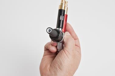
17 Assembly / Connection Connection instructions fig. 2: Connecting guide overview 1 Electrode rinsing air hose 2 OptiSelect GM03 manual gun 9 PowerClean module (Option) 10 Compressed air hose OptiFlex 2 F Assembly / Connection 17

18 3 Gun cable 4 Powder hose 5 Supplementary air hose 6 Conveying air hose 7 Control signal cable 8 Injector 11 Fluidizing air hose 12 Maintenance unit 13 OptiStar CG13 Gun control unit 14 Rinsing air hose 15 AirMover 16 Fluidized powder hopper Use clamp to connect grounding cable to the cabin or the suspension arrangement! Check ground connections with Ohm meter and ensure 1 MOhm or less! Close the unused connections with the provided dust protection caps! If no vibration motor (OptiFlex B) is connected, close the 2.2 Aux output with the dust protection cap! If no PowerClean module is connected, close also the 2.4 Purge connection with the dust protection cap! The compressed air must be free of oil and water! Connections Compressed air hoses / cables fig. 3: Connections Connection Description 1.1 Main air IN Compressed air connection 2.1 Power IN Mains cable connection 2.2 Aux Vibration motor connection for OptiFlex 2 B 2.3 Gun Gun cable connection 18 Assembly / Connection OptiFlex 2 F

19 Connection Description 2.4 Power Clean Connection to rinsing module 1.2 Conveying air connection 1.3 Supplementary air connection 1.4 Electrode rinsing air connection 1.5 Fluid air connection Grounding connection Set head piece OptiFlex 2 F Assembly / Connection 19
20 20 Assembly / Connection OptiFlex 2 F

21 Start-up Initial start-up If a malfunction occurs, see the troubleshooting guide, as well as the gun control unit operating manual! Fig. 4 The remainder of the start-up procedure for the Gun is explicitly described in the operating instructions for the OptiStar CG08/CG13 powder gun control unit (chapter "Initial start-up" and "Start-up")! OptiFlex 2 F Start-up 21
22 Setting the device type If the control unit is supplied as a component of an OptiFlex 2 complete unit, then the corresponding system parameter is set correctly by the factory. ATTENTION A wrong parameterization leads to various malfunctions! For more on this, please also see the operating instructions for the OptiStar CG13 gun control unit! 22 Start-up OptiFlex 2 F
23 Bedienung Rev /16 Operation WARNING Holding the gun incorrectly During the coating process, the gun can discharge along the body of the coater if not held using its intended handle, which has been grounded. Always hold gun only by the handle! Do not touch any other parts of the gun! Operation CAUTION Large dust formation possible! If the manual equipment is not being used for coating in conjunction with a sufficiently powerful suction unit, then the stirred-up dust from the coating powder can cause respiratory issues or cause a slippage/falling hazard. The manual equipment may only be operated in conjunction with a sufficiently powerful suction unit (such as Gema Classic Open booth). 1. Place powder hopper on the mobile trolley CAUTION Foot injury! When setting the powder hopper onto the mobile trolley of the manual equipment, the hopper/trolley zone represents a threat of crushed toes Wear safety shoes with steel toecaps. 2. Set the ventilation (Airmover) Open the ball valve completely Calibrate with the throttle valve 3. Fill in powder Open the powder hopper filling cover. Fill in powder: Fill with maximum 25 kg (50 l) powder or the powder must reach to a maximum of 5-10 cm below the handles OptiFlex 2 F Operation 23

24 of the powder hopper; otherwise the fluidized powder can escape from the cover. Close the filling cover of the powder hopper again. 4. Set coating parameters: 1. Turn on the gun control unit with the ON key 2. Press the corresponding application key. The arrow above the desired button lights up. The pre-defined application modes have preset values for high voltage and spray current: Application mode Preset µa Preset kv flat parts complicated parts overcoat The air values for total air, powder output and electrode rinsing air can be individually defined and are saved in the programs. Starting the user-defined operating mode (Program mode) 1. Turn on the gun control unit with the ON key 2. Press the program key 3. Select desired program (01-20) Program 20 active 4. Change coating parameters as required Programs are preset at the factory but can be modified at any time, after which they are automatically stored. 24 Operation OptiFlex 2 F
 Setting powder output and powder cloud The powder output depends on the selected powder output (in %), and the powder cloud on the selected total air volume.")
25 Description Powder output 60 % Total air High voltage Presetting 4.0 Nm³/h 80 kv Spray current 20 µa Electrode rinsing air Fluidizing air 0.1 Nm³/h 1.0 Nm³/h (for OptiFlex-F) 0.1 Nm³/h (for OptiFlex-B and S) Setting powder output and powder cloud The powder output depends on the selected powder output (in %), and the powder cloud on the selected total air volume. As a factory default value, a powder rate of 50% and a total air volume of 4 Nm³/h are recommended. If values are entered that the gun control unit cannot implement, then the operator is informed of this by a blinking in the relevant display and a temporary error message! Setting the electrode rinsing air 1. Press the key. The second display level will be shown. 2. Adjust the correct electrode rinsing air according to the applied nozzles (deflector plate, flat jet nozzle) 0,1 Nm³/h 0,5 Nm³/h too much electrode rinsing air 3. If in this display level is no operation for 3 seconds, the first display level is switched over independently. OptiFlex 2 F Operation 25
26 Setting the fluidization The powder fluidization depends on the powder type, the air humidity and the ambient temperature. Fluidizing and vibration start by switching on the control unit. 1. Press the key The second display level will be shown 2. Adjust the fluidizing air with the keys T5/T6 If in this display level is no operation for 3 seconds, the device switches back to the first display level 3. Check fluidization of the powder in the powder container The powder should only be touched gently, but should be "cooked" regularly and is also to be stirred using a rod CAUTION Large dust formation possible! If the fluidization has been incorrectly adjusted, then the coating powder can create a dust cloud capable of causing respiratory problems. Adjust the fluidization correctly. 4. Point the gun into the booth (not at the object to be coated), press the gun trigger and visually check the powder output 5. Check whether everything is functioning correctly 6. Coating 7. Adjust the coating parameters as necessary 8. Activate the rinsing function periodically 26 Operation OptiFlex 2 F
27 Rinsing mode The rinsing mode enables blowing off powder accumulations in the powder hose. Activating the rinsing function Manual equipment without optional PowerClean module (system parameter P01=0) The rinsing mode can only be activated from standby mode (main menu display, no powder conveying). On OptiFlex 2 F Manual coating equipment, the injector must be disconnected prior to cleaning procedure, on OptiFlex 2 B, the suction unit must be lifted, and on OptiFlex 2 S, the powder container must be empty. 1. Detach the injector 2. or 3. START = OptiFlex 2 F Operation 27
28 Procedure Automatic (automatic) Manual (manual) Effect The rinsing process is started Injector, powder hose, gun and spray nozzle are purged using compressed air The PowerClean function enables parallel cleaning of other components, such as the fluid intake unit, powder container, etc. The rinsing mode is exited if the automatic rinsing sequence has finished. The operator controls the number and length of the PowerClean impulse by pressing the gun trigger a second time 4. STOP = the cleaning mode is terminated automatically. or After completion of the PowerClean procedure, the controller switches back to coating mode. Manual equipment with optional PowerClean module (system parameter P01= 1 or P01=2) The rinsing mode can only be activated from standby mode (main menu display, no powder conveying). or 1. or 2. START = 28 Operation OptiFlex 2 F
29 Procedure Automatic (automatic) Manual (manual) Effect The rinsing process is started Injector, powder hose, gun and spray nozzle are purged using compressed air The PowerClean function enables parallel cleaning of other components, such as the fluid intake unit, powder container, etc. The rinsing mode is exited if the automatic rinsing sequence has finished. The operator controls the number and length of the PowerClean impulse by pressing the gun trigger a second time 3. STOP = the cleaning mode is terminated automatically. or After completion of the PowerClean procedure, the controller switches back to coating mode. or OptiFlex 2 F Operation 29


. 1. 2. 3. 4. 5.")

30 Color change General information When a color change takes place, the individual components of the manual coating equipment must be cleaned carefully. All powder particles of the former color must be removed during this process! The following describes an 'extreme' color change (light to dark) Remove and clean the nozzle, purge gun using air 30 Operation OptiFlex 2 F


31 Disconnect the fluidizing air supply 16. Remove cover, purge with compressed air and clean with a clean, dry brush and cloth 17. Clean the suction tube 18. Empty remaining powder into a container 19. Vacuum up the hopper and in particular the bottom 20. Clean container with a cloth 21. Reassemble the powder hopper 22. Fill with new powder OptiFlex 2 F Operation 31


32 Operation OptiFlex 2 F
33 Decommissioning / Storage Decommissioning 1. End the coating procedure 2. Switch off the control unit The adjustments for high voltage, powder output volume and electrode rinsing air remain stored. If in disuse for several days 1. Separate from power mains 2. Clean guns, injectors and powder hoses (see therefore the corresponding user manuals) 3. Turn off the compressed air main supply OptiFlex 2 F Decommissioning / Storage 33
34 34 Decommissioning / Storage OptiFlex 2 F
35 Maintenance / Repairs General information The product was designed for a maintenance-free operation. ATTENTION Any unauthorized modifications and alterations to the product are not permitted for safety reasons and exclude the manufacturer s liability for any resulting damage! Regular and conscientious cleaning and maintenance increase the service life of the product and ensure consistent high coating quality! The parts to be replaced during maintenance work are available as spare parts. These parts can be found in the appropriate spare parts list! Interval Daily maintenance 1. Clean the injector (see therefore the user manual of the OptiFlow injector) 2. Clean the powder gun (For more on this, please also review the user manual for the OptiSelect GM03 manual powder gun) 3. Clean the powder hose; Please also review the section "Color change" Weekly maintenance 1. Clean powder container, injector, rinsing module** and powder gun. 2. Check the control unit grounding connections to the coating booth, the suspension devices of the work pieces, or the conveyor chain OptiFlex 2 F Maintenance / Repairs 35
36 If in disuse for several days 1. Separate from power mains 2. Clean the coating equipment 3. Turn off the compressed air main supply Powder hose rinsing If longer downtimes take place, the powder hose has to be cleaned. Procedure: 1. Disconnect the powder hose from the hose connection on the injector 2. Point the gun into the booth 3. Blow through the hose manually with a compressed air gun 4. Connect the powder hose again to the hose connection on the injector Gun maintenance The gun is designed to require only a minimum amount of maintenance. 1. Clean the gun with dry cloth, see chapter "Maintenance" 2. Check connection points to powder house. 3. Replace the powder hoses, if necessary. 36 Maintenance / Repairs OptiFlex 2 F
37 Reinigung Rev /16 Cleaning CAUTION Large dust formation possible! If no dust mask or one of an insufficient filter class is worn when cleaning the product, then the dust that is stirred up from the coating powder can cause respiratory problems. The ventilation system must be turned on for all cleaning work. A dust mask corresponding to filter class FFP2 or N95 at minimum must be worn during any cleaning work. Gun cleaning ATTENTION Impermissible solvents The following solvents may not be used to clean the gun: Ethylene chloride, acetone, ethyl acetate, methyl ethyl ketone, methylene chloride, premium gasoline, turpentine, tetrachloromethane, toluene, trichloroethylene, xylene! Only cleaning agents with a flash point of a least 5 Kelvin above the ambient temperature, or cleaning places with technical ventilation are allowed! Before cleaning the powder gun, switch off the control unit. The compressed air used for cleaning must be free of oil and water! Daily: 1. Blow off the outside of the gun and wipe, clean etc. Weekly: 2. Remove powder hose 3. Remove the spray nozzle from the gun and clean it with compressed air 4. Blow through the gun with compressed air, beginning from the connection in flow direction 5. Blow through the gun with compressed air, beginning from the connection in flow direction 6. Clean the integrated gun tube with the brush supplied if necessary 7. Blow through the gun with compressed air again 8. Clean the powder hose 9. Reassemble the gun and connect it OptiFlex 2 F Maintenance / Repairs 37
38 Cleaning the powder container ATTENTION Damage to the fluidizing plate Never clean the powder container with solvents or water! 1. Disconnect the fluidizing air supply 2. Remove the injector 3. Remove PowerClean module** 4. Remove the cover, blow out with compressed air and clean with a clean dry brush and cloth 5. Clean the injector and suction intake pipe (Please review injector manual for more on this) 6. Clean rinsing module** 7. Empty remaining powder into a container 8. Vacuum up the hopper and in particular the bottom 9. Clean container with a cloth 10. Reassemble the powder hopper Do not refill the powder container until just before the next use! 38 Maintenance / Repairs OptiFlex 2 F
39 Fault clearance Prior to any troubleshooting measures, always check whether the equipment parameter (P00) as configured in the control unit is correct See operating instructions for the OptiStar CG13 manual gun control unit, Chapter "Initial Start-up Setting Equipment Type"! Incident Causes Corrective action H11 (Help code on control unit) Control unit displays remain dark, although the control unit is switched on Gun LED remains dark, although the gun is triggered Powder does not adhere to object, although the gun is triggered and sprays powder The gun does not spray powder, although the control unit is switched on and the gun trigger is pressed Gun not connected Gun plug or gun cable defective Remote control on powder gun defective Control unit is not connected to the mains Power pack fuse defective Power pack defective High voltage adjustment is set too low Gun plug or gun cable defective LED on gun defective High voltage and current deactivated High voltage cascade defective The objects are not properly grounded Compressed air not present Injector or nozzle on the injector, powder hose or powder gun clogged Insert sleeve in the injector is clogged Fluidization not running Connect the gun Contact local Gema representative Contact local Gema representative Connect the equipment with the mains cable Replace the fuse Contact local Gema representative Increase high voltage Contact local Gema representative Contact local Gema representative Check the high voltage and current setting Contact local Gema representative Check the grounding Connect the equipment to the compressed air Clean the corresponding part Clean/replace see below OptiFlex 2 F Fault clearance 39
40 Incident Causes Corrective action Gun achieving only poor spray profile No electrode rinsing air Pressure valve in the control unit defective Solenoid valve in the control unit defective No conveying air: Throttle motor defective Solenoid valve defective Front plate defective Total air incorrectly configured Bend or damage to air lines to injector Insert sleeve in the injector worn or not inserted Fluidization not running Rinsing air throttle motor defective Replace Replace Contact local Gema representative Contact local Gema representative Increase the powder quantity and/or total air volume on the control unit Check air lines to injector Replace or insert it see below Contact local Gema representative The powder is not fluidized Compressed air not present Connect the equipment to the compressed air Powder flows out of the powder hopper Fluidizing air is set too low on the control unit Throttle motor defective Airmover pressure incorrectly set Set the fluidizing air correctly Contact local Gema representative Adjust 40 Fault clearance OptiFlex 2 F
41 OptiStar CG13 For further information, see the corresponding operating manual, which can be found on the accompanying CD. Design and function Overall view fig. 5: 1 Front plate with control and display elements 2 Enclosure 3 Back panel with interfaces OptiFlex 2 F OptiStar CG13 41

42 Operating elements Displays The desired and actual values are distributed across several levels. The "sel" key is used to switch between the levels. If no controls are used within 6 s, the device automatically returns to level 1. fig. 6: Displays, Level 1 Designation A1-A4 A5 Function Display of actual values, desired values and system parameters Flashes if the possible range is exceeded. Display of program numbers, error diagnosis codes and status information S1 Powder output (display in %) S4 S7 S9 S12 remote S13 S15 Total air volume (display in Nm³/h) High voltage (display in kv) Spraying current (display in µa) Remote operation mode is used as keyboard lock, reduced operation is possible Activation of vibration/fluidization Display of predefined operating modes or display of rinsing mode during cleaning 42 OptiStar CG13 OptiFlex 2 F
 S19 Display illumination (0-8) Input keys and switches fig.")
 with optional")
43 fig. 7: Displays and LEDs, Level 2 Designation Function S3 Electrode rinsing air (display in Nm³/h) S6 Fluidizing (display in Nm³/h) S19 Display illumination (0-8) Input keys and switches fig. 8: Input keys and switches Designation T1-T8 T9 (Select) T10-T11 Function Input keys for desired values and system parameters Switch between display levels Program change Terminating the rinsing mode (PowerClean) with optional PowerClean module OptiFlex 2 F OptiStar CG13 43
44 Designation T12 T13 T14 T15 T16/T17 Function Switching on and off the fluidization (OptiFlex F) Switch on/off for vibration and fluidization (OptiFlex B) Switching on and off the stirrer (OptiFlex S) Switchover to system parameter mode (press for at least 5 secs.) Preset mode for flat parts (fixed values) Preset mode for complex parts with depressions (fixed values) Preset mode for overcoating parts already coated (fixed values) Switching on the rinsing mode (PowerClean) with optional PowerClean module (Press for at least 5 secs.) Power switch On/Off 44 OptiStar CG13 OptiFlex 2 F
45 Fault clearance Error diagnosis of the software General information The correct function of the Gun control unit is constantly monitored. If the equipment software determines a fault, an error message is indicated with a help code. Following is monitored: High voltage technology Pneumatic system Power supply Help codes The error diagnosis codes (help codes) are shown in red on the A5 display. The help codes are stored in an error list in the order of their appearance. Each error in the list must be individually acknowledged with the keys T10 or T11. The errors are displayed in the order of their appearance. The T10 and T11 keys cannot be used for other functions, as long as an error code is still shown. Here is a list of all possible help codes for this Gun control unit: OptiFlex 2 F Fault clearance 45
46 Code Description Criteria Remedy Pneumatics: H05 H06 H07 H08 H09 H10 High voltage: H11 H13 H14 PowerClean valve Trigger valve Supplementary air volume too high (setting of supplementary air on the display) Conveying air volume too high (setting of powder share on the display) Powder output higher than 100% Conveying air range lower deviation Gun error Power supply: H21 Intermediate circuit voltage too high Offset spray current measurement Supply undervoltage EEPROM (equipment memory): H24 H25 H26 EEPROM content invalid Timeout during EEPROM writing Values not correctly stored in EEPROM during switching off PowerClean valve not connected Valve defective Connection cable defective Mainboard defective Solenoid coil current lower than preset limiting value Valve defective, main board or cable defective The preset value for supplementary air is too high compared to the conveying air setting The preset value for conveying air is too high compared to the supplementary air setting The powder output multiplied by the powder hose length factor and daily correction value is greater than 100% Daily correction value too large The theoretical value for conveying air falls below minimum Total air is smaller than minimum No vibrations in the oscillator, cable break, oscillator or gun is defective Mainboard defective, device is switched off Grounded current measurement Power pack defective or overloaded EEPROM error EEPROM error EEPROM error connect or replace Contact a Gema service center Contact a Gema service center Lower supplementary air value or increase value for conveying air to equalize air volumes to the injector, delete error code Lower conveying air value or increase value for supplementary air to equalize air volumes to the injector, delete error code Reduce powder output Reduce daily correction value Limit conveying air to its minimum value Contact a Gema service center Contact a Gema service center Contact a Gema service center Contact a Gema service center Contact a Gema service center Contact a Gema service center Contact a Gema service center 46 Fault clearance OptiFlex 2 F
47 Code Description Criteria Remedy H27 Throttle motors: H60 H61 H62 H64 H65 H66 H68 H69 H70 H71 EEPROM verification erroneous Conveying air reference position not found Supplementary air reference position not found Electrode rinsing air reference position not found Conveying air throttle does not move Supplementary air throttle does not move Electrode rinsing air throttle does not move Conveying air position lost Supplementary air position lost Electrode rinsing air position lost Fluidizing air position lost Communication mainboard-gun: H90 H91 H92 Communication error Mainboard Communication error mainboard-gun Communication error Mainboard EEPROM error Throttle motor or needle jammed, limit switch defective, error in motor throttle Throttle motor or needle jammed, limit switch defective, error in motor throttle Throttle motor or needle jammed, limit switch defective, error in motor throttle Short circuit in limit switch, motor throttle defective Short circuit in limit switch, motor throttle defective Short circuit in limit switch, motor throttle defective Lost steps, limit switch defective, throttle motor defective Lost steps, limit switch defective, throttle motor defective Lost steps, limit switch defective, throttle motor defective Lost steps, limit switch defective, throttle motor defective Mainboard defective Gun not connected Gun, gun cable or Mainboard defective Mainboard defective Contact a Gema service center Contact a Gema service center Contact a Gema service center Contact a Gema service center Contact a Gema service center Contact a Gema service center Contact a Gema service center Contact a Gema service center Contact a Gema service center Contact a Gema service center Contact a Gema service center Contact a Gema service center connect Replace or contact Gema Service Contact a Gema service center Help codes list The last appeared four errors are stored in a list by the software. If an error appears, which is already in the list, he will not be listed again. Appearance of errors It is possible that an error is only displayed for a short time, but after the acknowledgement it will disappear. In this case, it's recommended to switch off the control unit and switch it on again (reset by restarting). OptiFlex 2 F Fault clearance 47
48 48 Fault clearance OptiFlex 2 F

49 OptiSelect GM03 For further information, see the corresponding operating manual, which can be found on the accompanying CD. Structure Overall view fig. 9: 1 Spray nozzle system 2 Threaded sleeve 3 Shaft 4 Cover with remote control and hooks 5 Remote control 6 SuperCorona connection 7 Gun handle 8 Gun cable 9 Powder hose connection 10 Powder hose quick release connection 11 Electrode rinsing air connection 12 Trigger OptiFlex 2 F OptiSelect GM03 49
 Powder output + key Powder output key Activate/stop rinsing process key Scope of delivery Manual gun with gun cable (6 m),")
50 Operating elements LED and remote control buttons fig. 10 Designation L1 T1 T2 T3 Function Display High voltage (intensity) Powder output + key Powder output key Activate/stop rinsing process key Scope of delivery Manual gun with gun cable (6 m), negative polarity Powder hose (6 m, ID 10 mm) Rinsing air hose (6 m) Flat jet nozzle NF20, complete (incl. electrode holder) Flat jet nozzle NF21 Cable tie with Velcro closure Gun cleaning brush Spare parts kit Operating manual Available accessories** Rinsing module (with OptiStar CG09/CG13 manual powder gun control unit only) SuperCorona ring Flat jet nozzle (for specific applications) Round jet nozzles Gun extension 150 and 300 mm Gun cable extensions Application cup 150 and 500 ml Multi-spray adapter 50 OptiSelect GM03 OptiFlex 2 F
51 Various adapters for connection to earlier generations of control units Gloves, anti-static **for more information, see spare parts list Technical Data Electrical data OptiSelect GM03 Nominal input voltage Frequency Nominal output voltage Polarity eff. 10 V 18 khz (average) 100 kv Max. output current 100 µa High voltage display Ignition protection Temperature range Max. surface temperature Protection type negative (optional positive) with LED Ex 2 mj T6 0 C C (+32 F F) 85 C (+185 F) IP64 Approvals 0102 II 2D PTB 11 ATEX 5006 Dimensions OptiSelect GM03 Weight Processible powders OptiSelect GM03 Plastic powder Metallic powder Enamel powder 520 g yes yes no OptiFlex 2 F OptiSelect GM03 51
52 52 OptiSelect GM03 OptiFlex 2 F
53 Fault clearance Additional error descriptions are to be found also in the control unit operating instructions! Incident Causes Corrective action H11 (Help code on control unit) Gun LED remains dark, although the gun is triggered Powder does not adhere to object, although the gun is triggered and sprays powder The gun does not spray powder, although the control unit is switched on and the gun trigger is pressed Gun not connected Gun plug or gun cable defective Remote control on powder gun defective High voltage adjustment is set too low Gun plug or gun cable defective LED on gun defective High voltage and current deactivated High voltage cascade defective The objects are not properly grounded Compressed air not present Injector or nozzle on the injector, powder hose or powder gun clogged Insert sleeve in the injector is clogged Pressure valve in the control unit defective Solenoid valve in the control unit defective No conveying air: Throttle motor defective Solenoid valve defective Front plate defective Connect the gun Contact local Gema representative Contact local Gema representative Increase high voltage Contact local Gema representative Contact local Gema representative Check the high voltage and current setting Contact local Gema representative Check the grounding Connect the equipment to the compressed air Clean the corresponding part Clean/replace Replace Replace Contact local Gema representative Contact local Gema representative OptiFlex 2 F Fault clearance 53
54 Incident Causes Corrective action Gun achieving only poor spray profile Total air incorrectly configured Bend or damage to air lines to injector Insert sleeve in the injector worn or not inserted Fluidization not running Increase the powder quantity and/or total air volume on the control unit Check air lines to injector Replace or insert it see above 54 Fault clearance OptiFlex 2 F
55 OptiFlow IG06 For further information, see the corresponding operating manual, which can be found on the accompanying CD. Structure Overall view fig Check valve unit (supplementary air) 2. Powder hose quick release connection 3. Powder hopper connection 4. Injector housing 6. Check valve unit (conveying air) OptiFlex 2 F OptiFlow IG06 55
56 Powder volume setting for OptiFlow Injector In order to set the ideal powder volume on the OptiStar gun control unit, it is recommended to select the firmness of the powder cloud or the total air first. As guide values for different powder hoses, the following can be assumed: Powder hose 74 type, Ø 10 mm, 3-5 m³/h Powder hose 66 type, Ø 11 mm, 4-5 m³/h According to the prevailing conditions (powder, powder hose layout, the parts to be coated) a low to lowest total air can also be set with the standard hose 74 type, Ø 10 mm. If a very large powder output is required, it is recommended to select a larger powder hose internal diameter (Ø 12 mm). It should to be noted, that if irregular or pumping conveying occurs, as a rule, the total air is set too low! 56 OptiFlow IG06 OptiFlex 2 F
57 Reinigung Rev /16 Maintenance / Repairs Cleaning ATTENTION Any unauthorized modifications and alterations to the product are not permitted for safety reasons and exclude the manufacturer s liability for any resulting damage! Regular and conscientious cleaning and maintenance increase the service life of the product and ensure consistent high coating quality! The parts to be replaced during maintenance work are available as spare parts. These parts can be found in the appropriate spare parts list! Cleaning the injector 1. Remove the injector 2. Remove the powder hose from the hose connection (2) 3. Clean the hose connection (2) with compressed air which is free of oil and water, and check for wear 4. Clean the injector body (4) with compressed air which is free of oil and water. Any contamination can be seen through the opening of the hopper fitting (3) 5. If the injector is severely fouled, it must be dismantled ATTENTION Injector parts may be damaged during the cleaning process. Remove the check valve units (1 and 6) with the correct sized spanner. Clean the component parts with compressed air and, if necessary, dissolve sintered deposits with nitro-thinner. Do not use acetone, do not scrape! 6. Reinsert the injector and fix it OptiFlex 2 F Maintenance / Repairs 57
 Cleaning the check valve units ATTENTION Parts of the check valve unit may be damaged during the dismantling process.")
58 fig Check valve unit (supplementary air) 2. Powder hose quick release connection 3. Powder hopper connection 4. Injector housing 6. Check valve unit (conveying air) Cleaning the check valve units ATTENTION Parts of the check valve unit may be damaged during the dismantling process. Blow off the filter elements from the inside to the outside! Do not immerse the filter elements in fluidities or solvents fig Connection/plug 2 O-ring 3 Filter element 58 Maintenance / Repairs OptiFlex 2 F


59 Replacing the insert sleeve OptiFlex 2 F Maintenance / Repairs 59
60 60 Maintenance / Repairs OptiFlex 2 F
61 Fault clearance Faults The following lists possible faults during operation and their clearance. Fault Cause Corrective action The gun does not spray powder although the control unit is switched on Gun achieving only poor spray profile Insert sleeve is worn after a short operating duration Injector nozzle, check valve unit, powder hose or powder gun are clogged Conveying vacuum too low Insert sleeve worn, not or incorrect inserted Clean the corresponding parts and if necessary, replace them Increase the powder quantity and/or total air volume on the control unit Replace or install the insert sleeve. Observe the indexing cam! Clean the nozzle, if damaged, replace it OptiFlex 2 F Fault clearance 61
62 62 Fault clearance OptiFlex 2 F
63 Spare parts list Ordering spare parts When ordering spare parts for powder coating equipment, please indicate the following specifications: Type and serial number of your powder coating equipment Order number, quantity and description of each spare part Example: Type OptiGun GA03 automatic powder gun Serial number Order no , 1 piece, Clamp Ø 18/15 mm When ordering cable or hose material, the required length must also be given. The spare part numbers of this bulk stock is always marked with an *. Wearing parts are always marked with a #. All dimensions of plastic hoses are specified with the external and internal diameter: Example: Ø 8/6 mm, 8 mm outside diameter (o/d) / 6 mm inside diameter (i/d) ATTENTION Use of non-original Gema spare parts When using the spare parts from other manufacturers the explosion protection is no longer guaranteed. If any damage is caused by this use all guarantee claims become invalid! Only original Gema spare parts should be used! OptiFlex 2 F Spare parts list 63
64 OptiFlex 2 F Spare parts list 1 OptiStar CG13 gun control unit complete (see corresponding operating manual) GM03 manual powder gun complete (see corresponding user manual) OptiFlow IG06 injector complete (see corresponding user manual) Pneumatic connection for conveying air complete (incl. Pos. 4.1, 4.2, 4.3) 4.1 Quick release connection NW5, Ø 8 mm, red Nut with kink protection M12x1 mm, Ø 8 mm Plastic tube Ø 8/6 mm, red * 5 Pneumatic connection for supplementary air complete (incl. Pos. 5.1, 5.2 and 5.3) 5.1 Quick release connection NW5, Ø 8 mm, black Nut with kink protection M12x1 mm, Ø 8 mm Plastic tube Ø 8/6 mm, black * 6 PowerClean module** complete (See operating instructions OptiSelect GM03 manual powder gun) 7 Pneumatic connection for PowerClean air** complete (incl. Pos. 7.1 and 7.2) Quick release connection** NW5, Ø 8 mm Hose** Ø 8/6 mm, black * 8 Powder hopper complete (without pos. 3) Pneumatic connection for conveying air complete (incl. Pos. 9.1, 9.2 and 9.3) 9.1 Quick release connection NW5, Ø 6 mm Nut with kink protection M10x1 mm, Ø 6 mm Plastic tube Ø 6/4 mm, black Pneumatic group complete (see corresponding spare parts list) 11 Quick release connection NW7,8-Ø 10- Ø 26 mm Airmover complete Rubber buffer Ø 35x40 mm, M8 mm Powder hose Ø 15/10 mm, 6 m *# 15 Short description Operating manual * Please indicate length # Wearing part 64 Spare parts list OptiFlex 2 F

65 OptiFlex 2 F Spare parts fig. 14 OptiFlex 2 F Spare parts list 65

66 Pneumatic group Pneumatic group complete Filter cartridge 20 µm # 2 Plug Ø 8 mm # Wearing part fig. 15: Pneumatic group 66 Spare parts list OptiFlex 2 F
67 PowerClean module set** PowerClean module set rinsing air hose length 2 m (pos. 1, 2, 3, 4 8) PowerClean module set rinsing air hose length 12 m (pos. 1, 2, 3.1 8) PowerClean module** complete (See operating instructions OptiSelect GM03 manual powder gun) Solenoid valve complete PowerClean module cable complete, length 1 m PowerClean module cable complete, length 15 m Quick release connection NW5-Ø 8 mm Plastic tube Ø 8/6 mm, black * 6 Gasket (not shown) # 7 O ring Ø 16x2 mm, NBR70, anti-static (2x) (not shown) # 8 Cable tie (not shown) * Please indicate length # Wearing part fig. 16: PowerClean module set** OptiFlex 2 F Spare parts list 67

68 OptiStar CG13 Gun control unit OptiStar CG13 Gun control unit complete Front plate complete, see corresponding spare parts list 2 Enclosure 3 Backplate complete, see corresponding spare parts list 4 Cover fig Spare parts list OptiFlex 2 F
 1007 048 5.")
69 Front plate and power pack Front plate complete (pos. 1-12) Front plate with foil keyboard (pos. 5-8) OptiStar Mainboard complete Spacer sleeve Ø 3.1/6x15 mm 3 PCB "Powerboard" complete Spacer sleeve Ø 3.2/6x7 mm 5 Front frame complete (incl. pos. 5.1) Screw Screw M4x20 mm Front plate gasket Membrane keypad 9 Spacer sleeve Ø 3.6/7x5 mm 10 Display Washer Ø 3.2/7x0.5 mm 12 Locknut M3 13 Power pack 24 VDC fig. 18 OptiFlex 2 F Spare parts list 69

70 Inside back plate 1 Back plate gasket Motor throttle complete T-piece 1/4"- Ø 8- Ø 8 mm Solenoid valve Ø 8-Ø 8 mm, 24 VDC Motor throttle complete Plastic tube Ø 8/6 mm * 7 Fluidizing pad 1/8" Screw M4x16 mm * Please indicate length fig. 19: 70 Spare parts list OptiFlex 2 F
 103 500* 3.")
71 Connecting material 1 Quick release connection NW5, Ø 6 mm Hose Ø 6/4 mm * 2 Nut with kink protection M12x1 mm, Ø 8 mm Spraying air hose Ø 8/6 mm (black) * 2.2 Quick release coupling for spraying air hose NW5-Ø 8 mm Nut with kink protection M12x1 mm, Ø 8 mm Conveying air hose Ø 8/6 mm (red) * 3.2 Quick release coupling for transport air hose NW5-Ø 8 mm Hose Ø 8/6 mm * 5 Quick release connection NW 5-Ø 6 mm Hose Ø 6/4 mm * 6 Vibrator cable (constituent part of vibrator) 8 PowerClean module cable 1 m (option) PowerClean module cable 15 m (option) Mains cable CH Mains cable Schuko Mains cable USA Mains cable GB Mains cable AUS Mains cable China * Please indicate length fig. 20 OptiFlex 2 F Spare parts list 71
72 OptiSelect GM03 Spare parts list Only parts were included in the spare parts list, which the user can replace himself without problems! If the powder gun cable is defective, it is to be completely sent in for repair! A B OptiSelect GM03 manual powder gun complete negative polarity, incl. gun cable 6 m, rinsing air hose 6 m, flat jet nozzle, brush and parts kit, without powder hose OptiSelect GM03 manual powder gun complete positive polarity, incl. gun cable 6 m, rinsing air hose 6 m, flat jet nozzle, brush and parts kit, without powder hose Manual powder gun shaft OptiSelect GM03 (incl. cascade) with: Gun cable 2 m, negative polarity ( ) Gun cable 6 m, negative polarity ( ) Gun cable 12 m, negative polarity ( ) Gun cable 2 m, positive polarity (+) Gun cable 6 m, positive polarity (+) Gun cable 12 m, positive polarity (+) Gun body Cascade complete, negative polarity Cascade complete, positive polarity Print holder complete End plate with hook Grip complete (incl. pos. 5.1 and 5.2) Grub screw M3x8 mm Grip sealing Trigger complete Trigger cover Countersunk-head screw M4x6 mm SuperCorona connection Gun cable 2 m complete Gun cable 6 m complete Gun cable 12 m complete Rinsing air connection Rinsing air hose * 12 Powder tube complete # 13 Compression spring Clip ring Hose connection Ø mm complete (incl. pos 15.1) # Hose connection Ø 9-10 mm complete (incl. pos 15.1) # 15.1 O-ring for pos # 16 Threaded sleeve (see corresponding spare parts list) 72 Spare parts list OptiFlex 2 F
73 17 Nozzle (see corresponding spare parts list) 18 Cascade space gasket # Cleaning brush Ø 12 mm Parts set (not shown), consisting of: Flat jet nozzle NF # MultiSpray-Adapter NF # Cable clamp Hose connector complete, for hose interior Ø 9-10 mm Powder hose Ø 10 mm (not shown) *# Powder hose Ø 11 mm (not shown) *# * Please indicate length # Wearing part fig. 21: OptiSelect GM03 spare parts OptiFlex 2 F Spare parts list 73
74 PowerClean module (Option) PowerClean module complete Elastomer valve # 2 O ring Ø 16x2 mm, anti-static # 3 Fluidizing tube bearing Fluidizing tube Retaining bracket Gasket O-ring Ø 27x2 mm # Wearing part fig Spare parts list OptiFlex 2 F

75 SuperCorona 1 SuperCorona PC # # Wearing part Fig. 23 OptiFlex 2 F Spare parts list 75
 NF20 1010 090 NF20")


76 Accessories Flat jet nozzles overview (wearing parts) Application A B A + B Threaded sleeve Profiles/flat parts (standard nozzle) NF NF Profiles/flat parts NF NF Complex profiles and depressions NF NF Complex parts (deep recess); target spraying NF NF Large surfaces NF24* NF * not suitable for angled nozzles 76 Spare parts list OptiFlex 2 F


77 Round jet nozzle Overview (wearing parts) Application A B A + B Threaded sleeve Deflectors Suitable for large surfaces NS NS Ø 16 mm Ø 24 mm Ø 32 mm Ø 50 mm OptiFlex 2 F Spare parts list 77
78 Gun extensions Gun extensions L = 150 mm L = 300 mm without nozzle without nozzle with Flat jet nozzle NF with Round jet nozzle NS see NF27, NF20, NF21, NF24, NS04 see NF25, NF26, NS09 ATTENTION Connecting more than two extensions It is not permitted to connect more than two extensions together, in order to prevent the gun from being damaged by arising leverage force. The extensions (150 mm/300 mm) may be connected TO ONLY ONE ADDITONAL extension (150 mm/300 mm), if necessary. 78 Spare parts list OptiFlex 2 F
 1007 718 1007 719 Application A B A + B")


79 Spray nozzles for extensions overview (wearing parts) Application A B A + B Threaded sleeve Deflecto rs Profiles/flat parts NF NF Complex profiles and depressions NF NF Suitable for large surfaces NS NS Ø 16 mm Ø 24 mm Ø 32 mm Ø 50 mm OptiFlex 2 F Spare parts list 79


80 Powder hoses overview Powder hose (antistatic) Application Diameter Parts No.* Material Type Fast color changes Fast color changes - low powder flow Fast color changes - high powder flow Ø 11/16 mm POE 66 Ø 10/15 mm POE 74 Ø 12/18 mm POE 75 * Please indicate length Other accessories 150 ml 500 ml Application cup Gun extension cables L=6 m L=14 m Gloves, anti-static (1 pair) Spare parts list OptiFlex 2 F
Powder injector OptiFlow IG07
 Rev. 00 1011 527 EN Operating instructions and Spare parts list Powder injector OptiFlow IG07 Translation of the original operating instructions Documentation OptiFlow IG07 Copyright 2017 Gema Switzerland
Application cup for OptiFlex 2 GM03 manual powder gun
 En Operating instructions and spare parts list Application cup for OptiFlex 2 GM03 manual powder gun Translation of the original operating instructions Documentation OptiFlex GM03 application cup Copyright
Manual coating equipment OptiFlex 2 B
 En Quick reference guide Manual coating equipment Translation of the original operating instructions Documentation Copyright 2010 Gema Switzerland GmbH All rights reserved. This publication is protected
Manual gun OptiSelect GM03
 Rev. 01 1011 454 EN Operating instructions and Spare parts list Manual gun OptiSelect GM03 Translation of the original operating instructions Documentation OptiSelect GM03 Copyright 2018 Gema Switzerland
Manual coating equipment OptiFlex 2 B
 En Operating instructions and spare parts list Manual coating equipment OptiFlex 2 B Translation of the original operating instructions Documentation OptiFlex 2 B Copyright 2010 ITW Gema GmbH All rights
Robot gun RobotGun GM03-R
 Rev. 00 1011 533 EN Operating instructions and Spare parts list Robot gun RobotGun GM03-R Translation of the original operating instructions Documentation RobotGun GM03-R Copyright 2017 Gema Switzerland
Powder coating equipment OptiFlex 2 BN (Boron Nitride)
") En Operating instructions and spare parts list Powder coating equipment OptiFlex 2 BN (Boron Nitride) WARNING: This equipment was developed for use with electrically non-conducting powders. The use of
En Operating instructions and spare parts list Powder coating equipment OptiFlex 2 BN (Boron Nitride) WARNING: This equipment was developed for use with electrically non-conducting powders. The use of
OptiSpray F Manual coating equipment
 En Operating instructions and spare parts list OptiSpray F Manual coating equipment Translation of the original operating instructions Documentation OptiSpray F Manual coating equipment Copyright 2006
OptiGun GA03 Automatic powder gun
 1010 772 En Operating instructions and spare parts list OptiGun GA03 Automatic powder gun 0102 II 2D Translation of the original operating instructions Documentation OptiGun GA03 Automatic powder gun Copyright
Manual powder gun OptiFlex 2 GM03
 En Operating instructions and spare parts list Manual powder gun OptiFlex 2 GM03 Translation of the original operating instructions Documentation OptiFlex 2 GM03 Copyright 2010 ITW Gema GmbH All rights
OptiFlow powder injector (IG02 type)
") En Operating instructions and spare parts list OptiFlow powder injector (IG02 type) Translation of the original operating instructions Documentation OptiFlow powder injector (IG02 type) Copyright 2004
En Operating instructions and spare parts list OptiFlow powder injector (IG02 type) Translation of the original operating instructions Documentation OptiFlow powder injector (IG02 type) Copyright 2004
OptiGun GA03-P Automatic powder gun
 1011 460 En Operating instructions and spare parts list OptiGun GA03-P Automatic powder gun 0102 II 2D Translation of the original operating instructions Documentation OptiGun GA03-P Automatic powder gun
Operating instructions and spare parts list. OptiFlow powder injector (IG02 type)
") En Operating instructions and spare parts list OptiFlow powder injector (IG02 type) Documentation OptiFlow powder injector (IG02 type) Copyright 2004 ITW Gema AG All rights reserved. This publication is
En Operating instructions and spare parts list OptiFlow powder injector (IG02 type) Documentation OptiFlow powder injector (IG02 type) Copyright 2004 ITW Gema AG All rights reserved. This publication is
WPS02 Waste powder conveying with BIG-BAG station
 En Operating instructions and spare parts list WPS02 Waste powder conveying with BIG-BAG station Translation of the original operating instructions Documentation WPS02 Copyright 2008 ITW Gema GmbH All
OptiFlow Plug-in injector (IG02)
") E Operating Instructions and Spare Parts List OptiFlow Plug-in injector (IG02) IG02 OptiFlow Injector 9 10 IG02 OptiFlow Injector Table of Contents 1 OptiFlow plug-in injector for organic powders...............................
E Operating Instructions and Spare Parts List OptiFlow Plug-in injector (IG02) IG02 OptiFlow Injector 9 10 IG02 OptiFlow Injector Table of Contents 1 OptiFlow plug-in injector for organic powders...............................
Quick reference guide. OptiFlex F. Manual coating equipment. Translation of the original operating instructions
 En Quick reference guide OptiFlex F Manual coating equipment Translation of the original operating instructions Quick reference guide OptiFlex F manual coating equipment Copyright 2006 Gema Switzerland
OptiGun 2-AE1 Enamel automatic gun (GA02-E1 type)
") En Operating instructions and spare parts list OptiGun 2-AE1 Enamel automatic gun (GA02-E1 type) II 2 D Translation of the original operating instructions Documentation OptiGun 2-AE1 Enamel automatic gun
En Operating instructions and spare parts list OptiGun 2-AE1 Enamel automatic gun (GA02-E1 type) II 2 D Translation of the original operating instructions Documentation OptiGun 2-AE1 Enamel automatic gun
Operating instructions and spare parts list. Waste powder conveying from recovery container WPS01
 En Operating instructions and spare parts list Waste powder conveying from recovery container WPS01 Documentation WPS01-PP03 Copyright 2006 ITW Gema GmbH All rights reserved. This publication is protected
FPS16 Fresh powder system
 En Operating instructions and spare parts list FPS16 Fresh powder system Translation of the original operating instructions Documentation FPS16 Fresh powder system Copyright 2005 Gema Switzerland GmbH
Operating instructions and spare parts list. LM01 Level sensor. Translation of the original operating instructions
 En Operating instructions and spare parts list LM01 Level sensor Translation of the original operating instructions Documentation LM01 Level sensor Copyright 2005 Gema Switzerland GmbH All rights reserved.
OptiCenter OC01 Powder management center
 En Operating instructions and spare parts list OptiCenter OC01 Powder management center Translation of the original operating instructions Documentation - OptiCenter OC01 Copyright 2009 Gema Switzerland
EasySelect GM01-E Manual Powder Gun
 E Operating Instructions and Spare parts list EasySelect GM01-E Manual Powder Gun EasySelect GM01-E 25 26 EasySelect GM01-E Table of Contents Safety rules Safety rules for electrostatic powder coating
EasySelect-Cup Manual Powder Gun
 E Operating Instructions and Spare parts list EasySelect-Cup Manual Powder Gun EasySelect-Cup 27 28 EasySelect-Cup Table of Contents Safety rules EasySelect-Cup Manual Powder gun...........................................
Operating instructions and spare parts list. OptiFlex F. Manual coating equipment
 En Operating instructions and spare parts list OptiFlex F Manual coating equipment Documentation OptiFlex B manual coating equipment Copyright 2005 ITW Gema AG All rights reserved. This publication is
Operating instructions and spare parts list OptiStar CG07 Manual gun control unit
 En Operating instructions and spare parts list OptiStar CG07 Manual gun control unit Order no. 1004 068 Documentation OptiStar CG07 Manual gun control unit Copyright 2006 ITW Gema AG All rights reserved.
OptiGun 2-AE Automatic Powder Gun (GA02)
") E Operating Instructions and Spare Parts List Automatic Powder Gun (GA02) 31 32 Table of Contents 1. Operating Instructions................................................... 1 1.1. Safety rules for electrostatic
E Operating Instructions and Spare Parts List Automatic Powder Gun (GA02) 31 32 Table of Contents 1. Operating Instructions................................................... 1 1.1. Safety rules for electrostatic
Operating instructions and spare parts list. OptiSelect. Manual powder gun
 En Operating instructions and spare parts list OptiSelect Manual powder gun Documentation OptiSelect manual powder gun Copyright 2005 ITW Gema AG All rights reserved. This publication is protected by copyright.
Operating instructions and spare parts list. OptiStar CG07 Manual Gun control unit
 En Operating instructions and spare parts list OptiStar CG07 Manual Gun control unit Documentation OptiStar CG07 Gun control unit Copyright 2005 ITW Gema AG All rights reserved. This publication is protected
Operating instructions and spare parts list. OptiFlex S. Manual coating equipment
 En Operating instructions and spare parts list OptiFlex S Manual coating equipment Documentation OptiFlex S manual coating equipment Copyright 2005 ITW Gema AG All rights reserved. This publication is
MagicCenter MC01 Powder management system
 En Operating instructions and spare parts list MagicCenter MC01 Powder management system Translation of the original operating instructions Dokumentation - MagicCenter MC01 Copyright 2008 ITW Gema GmbH
OptiCenter OC05 Powder management center
 1011 506 En Operating instructions and spare parts list OptiCenter OC05 Powder management center Translation of the original operating instructions Documentation OptiCenter OC05 Copyright 2008 Gema Switzerland
EASY 1-F Powder Coating Equipment
 E Operating Instructions and Spare parts list EASY 1-F Powder Coating Equipment 0102 II (2) D EASY 1-F ELECTROSTATIC POWER MANUAL EQUIPMENT 13 14 1 2 12 11 10 9 8 3 4 5 6 7 1 EasyTronic control unit 2
PG 1-A Automatic Powder Gun
 E Operating Instructions and Spare Parts List Automatic Powder Gun 25 26 Tabel of Contents Safety rules for electrostatic powder coating operations Automatic powder gun...........................................
Operating Instructions and Spare Parts List. PG 1-Cup Gun. Issued 09/98
 E Operating Instructions and Spare Parts List 27 28 Table of Contents Directions for use Electrostatic Manual Spraying equipment for Powder Coating Safety rules for the electrostatic powder coating Technical
OptiCenter OC02 Powder management center
 1011 502 En Operating instructions and spare parts list OptiCenter OC02 Powder management center Translation of the original operating instructions Documentation OptiCenter OC02 Copyright 2008 Gema Switzerland
Rev EN. Operating instructions and Spare parts list. Vertical axis ZA13. Translation of the original operating instructions
 Rev. 00 1011 516 EN Operating instructions and Spare parts list Vertical axis ZA13 Translation of the original operating instructions Documentation ZA13 Copyright 2017 Gema Switzerland GmbH All rights
MPS 1-F / MPS 2-F Manual Powder System
 E Operating Instructions and Spare Parts List MPS -F / MPS -F Manual Powder System MPS -F / MPS -F MPS -F / MPS -F Table of contents Directions for use Safety rules for the electrostatic powder coating
PI 1 Plug-in Injector
 Operating Instructions and Spare Parts List PI 1 Plug-in Injector PI 1 1 12 PI 1 Table of contents PI 1 Plug-in injector for organic powders................................... 1 Fields of application....................................................
RediCoat by Nordson. Hopper and VBF Dolly Systems. Customer Product Manual Part A Issued 10/07
 RediCoat by Nordson Hopper and VBF Dolly Systems Customer Product Manual Part 1082648A Issued 10/07 This document is subject to change without notice. Nordson Corporation Amherst, Ohio USA 2 Table of Contents
Operating Instructions and Spare Parts List. Tilt Table FPS13. Ausgabe 07/02. Tilt Table FPS13
 E Operating Instructions and Spare Parts List 15 Copyright 2000 ITW Gema AG., CH-9015 St. Gall All rights reserved. This publication is protected by copyright. Unauthorized copying is prohibited by law.
Operating instructions and spare parts list FPS14 Fresh powder system
 En Operating instructions and spare parts list FPS14 Fresh powder system 0102 II 3 D Documentation FPS14 Fresh powder system Copyright 2004 ITW Gema AG All rights reserved. This publication is protected
PG 2-A Automatic Powder Gun (and PG 2-AX Automatic Powder Gun for Quick Colour Changes)
") E Operating Instructions and Spare Parts List Automatic Powder Gun (and X Automatic Powder Gun for Quick Colour Changes) 31 32 Table of Contents Automatic Powder Gun...........................................
E Operating Instructions and Spare Parts List Automatic Powder Gun (and X Automatic Powder Gun for Quick Colour Changes) 31 32 Table of Contents Automatic Powder Gun...........................................
MPS 1-B / MPS 2-B Manual Powder System
 E Operating Instructions and Spare Parts List MPS -B / MPS -B Manual Powder System MPS -B / MPS -B 7 Issued / - V. Issued / - V. 8 MPS -B / MPS -B Table of Contents Directions for use Safety rules for
Operating instructions and spare parts list. PZ Powder center with Gematic control unit
 En Operating instructions and spare parts list PZ Powder center with Gematic control unit Documentation PZ Powder center with Gematic control unit Copyright 2004 ITW Gema AG All rights reserved. This publication
Operating instructions and spare parts list. XT08 Horizontal axis
 En Operating instructions and spare parts list XT08 Horizontal axis Documentation XT08 Copyright 2004 ITW Gema AG All rights reserved. This publication is protected by copyright. Unauthorized copying is
Swing Piston Compressors and Vacuum Pumps
 Swing Piston Compressors and Vacuum Pumps NPK 018 AC Pressure NPK 018 DC Pressure NPK 018 AC Vacuum NPK 018 DC Vacuum Operating and Installation Instructions Read and observe these Operating and Installation
CRS-D Powder Coating Booth with Reverse Jet Cleaning System
 Operating Instructions CRS-D Powder Coating Booth with Reverse Jet Cleaning System CRS-D (J) 27 1 1 1 2 2 2 4 4 4 3 3 3 CRS-D Booth with Reverse Jet Cleaning System 1 10 2 3 9 12 11 11 1 Exhaust air unit
Operating instructions and spare parts list. MagicCylinder II Powder coating booth
 En Operating instructions and spare parts list MagicCylinder II Powder coating booth Documentation - Powder coating booth MagicCylinder II Copyright 2007 ITW Gema GmbH All rights reserved. This publication
Operating instructions Accu Jet
 Operating instructions Accu Jet Keep for future use! Ident number: 04.8800.000 Air Line Table of contents 1 Scope of delivery... 4 2 Operator instructions... 5 3 Safety... 6 3.1 Intended use...8 4 Description
MPS 1-L Manual Powder System with the PG 1 Powder Gun
 bar... 0. m /h 00 00 90 90 0 0 0 0 0 0 0 0 0 0 0 0 0 0 0 0 kv µa E Operating Instructions and Spare Parts List MPS -L Manual Powder System with the PG Powder Gun 0 0 + m /h Issued 0/9 MPS -L / PG An ITW
XT 6 Horizontal Axis
 E Operating Instructions and Spare Parts List 11 12 Table of Contents................................................... 1 1. Field of Application........................................... 1 2. Description.................................................
Operating and Installation Instructions Swing Piston Compressors and Vacuum Pumps
 Operating and Installation Instructions Swing Piston Compressors and Vacuum Pumps UNPK04DC Pressure UNPK04DCB Pressure UNPK04DC Vacuum UNPK04DCB Vacuum KNF Neuberger, Inc 2 Black Forest Rd Trenton, NJ
Operating instructions
 Operating instructions Digital tank contents indicator DTA 10 DTA 10 DTA 10 0 4.0 m fuel oil 0 3.5 m water Read instructions before using device! Observe all safety information! Keep instructions for future
Oil-free piston compressors KK and piston vacuum pumps KV
 Oil-free piston compressors KK and piston vacuum pumps KV Installation and Operating Instructions 0678106030L02 1707V003 Contents Important information 1 About this document 2 1.1 Warnings and symbols
KeContact P20. User manual
 KeContact P20 User manual Comments to this manual In this manual you will find warnings against possible dangerous situations. The used symbols apply to the following meanings:!! WARNING! Indicates a potentially
Operator s Manual. Fairbanks FH Series by Fairbanks Scales, Inc. All rights reserved. . Revision 1 06/2017
 Operator s Manual Fairbanks FH Series 2017 by Fairbanks Scales, Inc. All rights reserved 51393. Revision 1 06/2017 Amendment Record Fairbanks FH Series Operator s Manual Operator s Manual Document 51393
Translation of the Original Operating Manual. Automatic Powder Spray Gun PEA-C4XL-S. Version 03 / II 2 D EEx 2mJ 85 C P_02330
 Translation of the Original Operating Manual Automatic Powder Spray Gun Version 03 / 2014 P_02330 0102 II 2 D EEx 2mJ 85 C Table of Contents 1 GENERAL INFORMATION 6 1.1 Preface 6 1.2 Warnings, Notices,
Operating instructions and spare parts list. FPS15 Tilt table
 En Operating instructions and spare parts list FPS5 Tilt table Documentation FPS5 Tilt table Copyright 004 ITW Gema AG All rights reserved. This publication is protected by copyright. Unauthorized copying
Prodigy HDLV Generation II Pump Panel
 Prodigy HDLV Generation II Pump Panel Customer Product Manual Issued 01/10 For parts and technical support, call the Finishing Customer Support Center at (800) 433-9319. This document is subject to change
Rotary feed-through DDF-S/-KS
 Translation of the Original Operating Manual Rotary feed-through DDF-S/-KS Assembly and Operating Manual Superior Clamping and Gripping Imprint Imprint Copyright: This manual remains the copyrighted property
USE and MAINTENANCE INSTRUCTION MANUAL AZ3 HTE2 AZ3 HTE2 HVLP GRAVITY. SPRAY GUN Series. en it fr es pt de se
 USE and MAINTENANCE INSTRUCTION MANUAL AZ3 HTE2 AZ3 HTE2 HVLP GRAVITY SPRAY GUN Series en it fr es pt de se TECHNICAL DATA Technical AZ3 HTE2 AZ3 HTE2 HVLP 1.0 80 180 1.3 10-15HTE 140 200 240 1.5 2.0 160
PTB 14 ATEX 2023 X, IECEx PTB X. Operating Instructions. Solenoid coil Type AC10 Magnetspule Typ AC10 Bobine magnétique Type AC10
 , IECEx PTB 14.0049X Solenoid coil Type AC10 Magnetspule Typ AC10 Bobine magnétique Type AC10 Device with II 2G/D Ex approval Geräte mit II 2G/D Ex Zulassung Appareils avec mode de protection II 2G/D Ex
Installation and operating instructions. Solar charge controller MPPT 10 A / 20 A Z Z
 Installation and operating instructions Solar charge controller MPPT 10 A / 20 A EN 1 Contents 1. About these instructions... 3 1.1 Applicability... 3 1.2 Users... 3 1.3 Description of symbols... 3 2.
Exchange of rollers from the XTS-Mover
 Service documentation for AT901-0050-0550 and AT9011-00x0-0550 Version: Date: 1.0 0.10.017 Table of contents Table of contents 1 Foreword... 5 1.1 Notes on the documentation... 5 1. Documentation issue
Prodigy HDLV Pump. Customer Product Manual Part A02
 Prodigy HDLV Pump Customer Product Manual Issued 1/07 For parts and technical support, call the Industrial Coating Systems Customer Support Center at (800) 433-9319 or contact your local Nordson representative.
Translation of the Original Operating Manual. Manual Powder Spray Gun PEM-X1. Version 09/2012. II 2D 2mJ P_01660
 Translation of the Original Operating Manual Manual Powder Spray Gun Version 09/2012 P_01660 0102 II 2D 2mJ Contents 1 GENERAL INFORMATION 6 1.1 Preface 6 1.2 Warnings, Notes and Symbols in these Instructions
EPS 16 ATEX 1072 X, IECEx EPS X. Operating Instructions. Solenoid coil Type AC19 Magnetspule Typ AC19 Bobine magnétique Type AC19
 , IECEx EPS 16.0030X Solenoid coil Type AC19 Magnetspule Typ AC19 Bobine magnétique Type AC19 Device with II 2G/D Ex approval Geräte mit II 2G/D Ex Zulassung Appareils avec mode de protection II 2G/D Ex
Installation and Operating Manual for Tank and Equipment Cleaning Nozzles Series 5TM
 Installation and Operating Manual for Tank and Equipment Cleaning Nozzles Series 5TM 150 150 150 This instruction manual contains proprietary information which is protected by copyright laws. No part of
Prodigy HDLV Pump Manifold and Circuit Board
 Prodigy HDLV Pump Manifold and Circuit Board Customer Product Manual Issued 05/08 For parts and technical support, call the Finishing Customer Support Center at (800) 433-939. This document is available
World Leaders in Diesel Fuel Injection Test Equipment. IFT-c. Injector Function Tester Controller. Operating and Servicing Manual
 World Leaders in Diesel Fuel Injection Test Equipment. IFT-c Injector Function Tester Controller Operating and Servicing Manual HL048 (EN) Issue 4, H1852, August 2011 HARTRIDGE LIMITED IFT-c Operating
Encore HD Powder Spray System with Prodigy Pump Cabinet
 Encore HD Powder Spray System with Prodigy Pump Cabinet Customer Product Manual Part 604979-06 Issued 05/8 For parts and technical support, call the Industrial Coating Systems Customer Support Center at
USE and MAINTENANCE INSTRUCTION MANUAL W-300 W-300 WB LPH-300 GRAVITY. SPRAY GUN Series. en it fr es pt de se
 USE and MAINTENANCE INSTRUCTION MANUAL W-300 W-300 WB LPH-300 GRAVITY SPRAY GUN Series en it fr es pt de se TECHNICAL DATA High T.E.C. series Nozzle_Needle set Combination W-300 WB W-300 W-300-081G 0.8
FL 10 DIAPHRAGM PUMP INSTALLATION INSTRUCTIONS. Before operating the pump, please read the Installation Instructions and safety precautions.
 FL 10 INSTALLATION INSTRUCTIONS DIAPHRAGM PUMP FL 10 DC-P FL 10 AC Before operating the pump, please read the Installation Instructions and safety precautions. Installation Instructions FL 10 Table of
Rolli D6/5A. Operating Instructions HORN GMBH & CO. KG. Product Description. Safety Indications. Mounting. Commissioning.
 Declaration of Conformity Operating Instructions Rolli D6/5A 440209101-A 03/2004 Subject to technical alterations. Text and design copyrighted. Reprinting and copying, even if excerpts, only with written
HST-BL-2830MS & HST-BL-2830MS-USA
 HST-BL-2830MS & HST-BL-2830MS-USA Release date: 02/2017 High - System - Technik Im Martelacker 12 D-79588 Efringen-Kirchen Phone 0 76 28-91 11-0 Fax 0 76 28-91 11-90 E-Mail: info@hs-technik.com Web: www.hs-technik.com
WELDING INVERTER. PEGAS 160 E Smart PEGAS 200 E Smart OPERATING MANUAL. ALFA IN a.s. PEGAS E Smart Manual EN 04
 WELDING INVERTER PEGAS 160 E Smart PEGAS 200 E Smart OPERATING MANUAL PEGAS 160-200 E Smart Manual EN 04 2/12 CONTENT: 1. INTRODUCTION... 3 2. SAFETY INSTRUCTIONS AND WARNINGS... 4 3. TECHNICAL DATA...
MANUAL. Single charger
 MANUAL Single charger HST-PR-2830 & HST-PR-2830USA for HS-Technik batteries HST-PR-18xx HST-PR-14xx issue date: November 2016 Table of contents Page 1. Basic information...3 1.1. Purpose of this document...3
Assembly and Maintenance Manual Type ASNU
 Assembly and Maintenance Manual Type ASNU Hatschekstr.36 69126 Heidelberg Germany Tel +49(0)6221 30470 Fax +49(0)6221 304731 info@stieber.de www.stieber.de Date of issue: 30.05.2018 GB Revision: 0 U:\EngUsers\!ProduktDoku\1AAA_Einbauerklaerung_Wartungsanleitung_Konformitaetserklaerung\1AAA_Wartungsanleitungen\Orginal_Worddatei\_ASNU.docx
2-PHASE STEPPING MOTOR DRIVER FE Z5 DISPENSE
 2-PHASE STEPPING MOTOR DRIVER FE Z5 DISPENSE For Diaphragm Dosing Pumps FEM 1.02_.55 / FEM 1.09_.55 Controller board package, without pump: ID 160536 Operating and Installation Manual It is important to
Instruction Manual. Automatic Fuel Oil De-aerator Flow-Control. Flow-Control 3/K-1 # Flow-Control 3/K-2 # 70019
 Mess-, Regel- und Überwachungsgeräte für Haustechnik, Industrie und Umweltschutz Lindenstraße 20 DE-74363 Güglingen Telefon: +49(0)7135-102-0 Service: +49(0)7135-102-211 Telefax: +49(0)7135-102-147 E-Mail:
Installation and operating instructions. Solar charge controller 10 A / 15 A / 0 A / 30 A PHOTOVOLTAIK - PHOTOVOLTAICS - PHOTOVOLTAIQUE - FOTOVOLTAICA
 PHOTOVOLTAIK - PHOTOVOLTAICS - PHOTOVOLTAIQUE - FOTOVOLTAICA Installation and operating instructions Solar charge controller 10 A / 15 A / 0 A / 30 A EN 74.86 08.4 1. About this manual These operating
Installation, Operating & Maintenance Instructions. UHV gate valve with pneumatic actuator. Series 108 DN mm (I. D. 2½ 8 )
") Installation, Operating & Maintenance Instructions UHV gate valve with pneumatic actuator Series 108 DN 63 200 mm (I. D. 2½ 8 ) This manual is valid for the following product ordering numbers: 108.. -.
Installation, Operating & Maintenance Instructions UHV gate valve with pneumatic actuator Series 108 DN 63 200 mm (I. D. 2½ 8 ) This manual is valid for the following product ordering numbers: 108.. -.
Big Bag Unloader. Customer Product manual Part Number Issued 07/17
 Big Bag Unloader Customer Product manual Part Number 7580188-01 Issued 07/17 For parts ordering, call the Industrial Coating Systems EU Customer Support Center on 0080070017001 or contact your local Nordson
Micro Diaphragm Gas Sampling Pumps
 Operating and Installation Instructions Micro Diaphragm Gas Sampling Pumps Type range: NMP 03 KP DC-B1 NMP 03 KP DC-S NMP 03 KP DC-B3 NMP 03 KP DC-M NMP 03 KP DC-L You have selected a high-quality KNF
Metallic Nozzle Convertion Kit - PG 1 to PG 1-M
 E Operating instructions and Spare Parts List Metallic Nozzle Convertion Kit - PG 1 to PG 1-M An ITW Company 1 Table of Contents Metallic Convertion Kit for the PG 1 Manual Powder Gun......................
ION JET NOZZLE NIH-55
 ION JET NOZZLE NIH-55 INSTRUCTION MANUAL - Read this instruction manual and make sure you thoroughly understand its contents before attempting to operate, inspect or service this product. - The users and
User Guide. Lubricus Lubrication System LUB-D1/LUB-D2/LUB-D3/LUB-D4 (24 VDC)
") User Guide Lubricus Lubrication System LUB-D1/LUB-D2/LUB-D3/LUB-D4 (24 VDC) version 04/2013 Content General Information 3 Warning 3 Scope of Supply 3 Overview 3 General safety details 4 Intended use 4
User Guide Lubricus Lubrication System LUB-D1/LUB-D2/LUB-D3/LUB-D4 (24 VDC) version 04/2013 Content General Information 3 Warning 3 Scope of Supply 3 Overview 3 General safety details 4 Intended use 4
Battery Charger. Series EASY Charger. User s manual
 Battery Charger Series EASY Charger User s manual 1 Warranty RIPEnergy is not manufacturer of these units. All technical information s, data s and dimensions rely on information s given by the manufacturer.
SCOPELITE TIMING LIGHT OPERATING MANUAL
 SCOPELITE TIMING LIGHT OPERATING MANUAL MOTORTECH Tools & Test Equipment for Ignition Systems P/N 01.10.020-EN Rev. 11/2015 Copyright Copyright 2015 MOTORTECH GmbH. All rights reserved. Distribution and
OPERATING MANUAL LA-BO. Applicator
 OPERATING MANUAL LA-BO Applicator Release 3-4/2017 Content General Notes & Safety Instructions -5 General notes -5 Validity and binding effect of this manual -5 Illustrations and descriptions -6 Safety
Installation and Operating Instructions. MPPT Solar System Controller ISC3040
 Installation and Operating Instructions MPPT Solar System Controller ISC3040 ABOUT THIS MANUAL These operating instructions come with the product and should be kept with it as a reference to all user s
Micro Diaphragm Gas Sampling Pumps
 Operating and Installation Instructions Micro Diaphragm Gas Sampling Pumps Type range: NMP830K_DC-M HP NMP830.1.2K_DC-M HP NMP830K_DC-B HP NMP830.1.2K_DC-B HP NMP830K_DC-B4 HP NMP830.1.2K_DC-B4 HP You
Installation and Operating Instructions. Solar System Controller ISC3030
 Installation and Operating Instructions Solar System Controller ISC3030 ABOUT THIS MANUAL These operating instructions come with the product and should be kept with it as a reference to all user s of the
DC Master 24/ A
 USERS MANUAL DC Master 24/12 50-60A DC-DC converter MASTERVOLT Snijdersbergweg 93, 1105 AN Amsterdam The Netherlands Tel.: +31-20-3422100 Fax.: +31-20-6971006 www.mastervolt.com ENGLISH Copyright 2015
Battery Charger Series EASY Charger
 Battery Charger Series EASY Charger User s manual 1 Warranty RIPEnergy is not manufacturer of these units. All technical information s, data s and dimensions rely on information s given by the manufacturer.
Printed: Doc-Nr: PUB / / 000 / 00
 ORIGINAL OPERATING INSTRUCTIONS Hilti HTE-P 33 dispenser It is essential that the operating instructions are read before the tool is operated for the first time. Always keep these operating instructions
Accessories for Wind Power Inverter WINDY BOY PROTECTION BOX 400 / 500 / 600
 Accessories for Wind Power Inverter WINDY BOY PROTECTION BOX 400 / 500 / 600 Installation Guide WBP-Box-IEN103320 IMEN-WBP-BOX Version 2.0 EN SMA Solar Technology AG Table of Contents Table of Contents
Diaphragm Vacuum Pumps and Compressors
 Operating Instructions Read and observe these Operating Instructions! Diaphragm Vacuum Pumps and Compressors N145 AN.18 N145 AT.18 N145 AV.18 N145.1.2 AN.18 N145.1.2 AT.18 N145.1.2 AV.18 KNF Neuberger
Drive Unit e-drive1. Installation instructions 04/2014. English translation of the original German installation instructions
 Drive Unit e-drive1 Installation instructions 04/2014 English translation of the original German installation instructions Contents Foreword... 3 Availability... 3 Structural features in the text... 3
Swing Piston Compressors and Vacuum Pumps
 Swing Piston Compressors and Vacuum Pumps NPK 050 NPK 0100 Operating and Installation Instructions Read and observe these Operating and Installation Instructions! KNF Neuberger GmbH Alter Weg 3 D-79112