IS13.5 IS18.5 IS23 USAGE AND MAINTANENCE MANUAL
|
|
|
- Maude Wells
- 5 years ago
- Views:
Transcription

1 IS1.5 IS18.5 IS USAGE AND MAINTANENCE MANUAL #19601

2
3


4 1 TAB "A"
 11 8 4 1 9")
5 4 5 (/16") 10 mm (/8")
6 1 10 6
7 11 7
8 f 8 1
9 1 9
10 10 14
11 15 11
12 CONTENTS Figure... Wiring diagrams GENERAL INFORMATION Purpose of the manual Attached documents Machine identification Safety standards GENERATOR DESCRIPTION Introduction Generator composition Cooling system Control panel USING THE GENERATOR Preliminary checks Bleeding the air from the supply system Start-up Stop PREVENTATIVE SHUT DOWNS Low oil pressure shut down High water temperature shut down Alternator thermal overload shut down Short circuit and overload shut down Short circuit and overload shut down for the battery charger DC alternator Short circuit shut down for the low voltage electric system MAINTENANCE Routine maintenance of the engine Changing engine oil and oil filter Cleaning the air filter Replacing the fuel filter Checking the cooling liquid Checking the tension of the V-belts Emptying the cooling system Replacing the cooling liquid Replacing zinc anodes Alternator maintenance Battery maintenance Periods of inactivity Table of scheduled maintenance tasks Fault table SPECIFICATIONS References for wiring diagrams
13 1 GENERAL INFORMATION Carefully consult this manual before proceeding with any operation on the generator. THE WARRANTY OF THE PRODUCT MAY BE VOIDED IF THE SPECIFICATIONS CONTAINED IN THIS INSTALLATION MANUAL ARE NOT FOLLOWED. 1.1 Purpose of this manual Thank you for choosing a Mase product. This manual is written by the manufacturer for the purpose of providing essential information and instructions for safety, proper use. and maintenance. This manual must be safely stored with the boat owner information for the entire life of the generator and must accompany the generator if transferred to another user or owner. The information contained in the manual is addressed to all those persons involved in the operating life cycle of the generator, and is necessary to inform those who use the genset, are around the genset, and who perform maintenence and/or repair. This manual defines the purpose for which the generator was constructed and contains all the information necessary to guarantee safe and proper use. Observance of the instructions contained in this manual ensures the safety of the operator, operating economy and longer life of the generator. It is strongly recommended to carefully read the contents of this manual and the reference documents to inform yourself of the regular function and maintenence to ensure the safetly of those using the generators and the reliability of the generator itself. Drawings are provided by way of example. Even if your generator differs considerably from the illustrations contained in this manual, the safety of the generator and the information provided are still appropriate and important. Note: the information contained in this publication is correct at the time of printing. The manufacturer in his pursuit of a policy of constant development and upgrading of the product reserves the right to make modifications without prior notice. SYMBOLS Those parts of the text not to be ignored are highlighted in bold type preceded by a symbol, as illustrated and defined below. Indicates that particular attention must be paid in order to prevent running into serious danger which could lead to death or possible hazards to the health of personnel. A condition which may occur during the lifetime of a product, system or plant considered at risk regarding damage to persons, property, the environment or economic loss. or other property. Indicates that particular attention must be paid in order to prevent serious damage to the product Instructions of particular importance. 1
14 1. Attached documents The following documents are an integral part of this manual. - EC declaration of conformity; - Engine use and maintenance manual; - Installation manual; - Service manual; - Warranty certificate; - Warranty card; 1. Machine identification See FIG Machine code - Year of manufacture - Power factor 4 - Declared frequency 5 -Continuous output 6 - Nominal voltage 7 - Current 8- Serial number 1.4 Safety standards - Read all the information contained in this manual and in the installation manual carefully; it is essential for the correct installation and use of the generator and enables appropriate action to be quickly taken if it is required. - Do not allow unauthorized persons to use the generator and do not allow anyone to use the generator without adequate training. - Prevent children or animals from approaching the generator while it is in operation. - Do not approach the generator or remote control panel if your hands or any other part of your body is wet as the generator can be a source of electric shocks if it is incorrectly used. - Switch off and lock out the engine before carrying out checks on the generator; only expert personnel are authorized to check the generator whilst it is operating. - Do not breath the combustion fumes as they contain harmful substances. If oil or fuel leaks occur, clean them thoroughly in order not create a fire hazard. Do not use water to put out fires: use extinguishers.. GENERATOR DESCRIPTION.1 Introduction The IS1.5, 18.5, and series generators have been designed for easy installation on boats. The soundproof structure consists of panels in marine aluminium. These panels provide easy access to the engine and the alternator for maintenance and inspections while, at the same time, considerably reducing sound levels. The direct-injection 4-stroke diesel engine by Yanmar is reliable and efficient. The 4-pole synchronous alternator has no brushes and has an electronic voltage adjuster (SR7) that guarantees fluctuations from nominal voltage are no greater than ± 5%. The alternator s surge capacity makes the generator ideal for supplying the electric motors of conditioners, desalination units, compressors, etc. IS1.5,18.5 and generators have a local control panel [fig.1 ref.9] on which the controls and control instruments are located.. Generator composition The generator consists of: - a sound shield [fig.1 ref.10]; - an engine [fig.1 ref.11]; - an alternator unit [fig.1 ref.1]; - a water - water exchanger [fig.1 ref. 1]; - an air water - exchanger [fig.1 ref.14]; - a support base [fig.1 ref.15];. Cooling system The generator engine is cooled by a closed circuit raw sea water heat exchanger. The exchanger is in cupronickel and has been specially designed by Mase to enable the engine to be used in marine applications. When installing it, a wet exhaust system must be installed to discharg the combustion fumes and the water that has been used for cooling..4 Control panel A control panel is located on the generator to enable checks to be made and the generator to be started and stopped. An engine overload protection module [fig., ref. 1] manages generator overload protection, cuts out the engine in the event of a fault, and sends an alarm signal by means of the warning lights. 14
15 -If the green warning light RUN [fig., ref. ] is lit up it means the generator is running and no operating fault has been detected. -If the red warning light BATT. [fig., ref. ] illuminates it means the battery charger alternator is faulty. -If the red warning light OIL [fig., ref. 4] illuminates it means engine oil pressure is too low. -If the red warning light C illuminates it means the temperature of the cooling liquid or the water in the heat exchangers is too high. -If the red warning light C illuminates it means the temperature of the alternator coils is too high. The control panel also contains: -a two-pole circuit breaker [fig., ref. 7] that interrupts the current in the event of an overload or short circuit; -a circuit breaker switch [fig., ref.8] to protect the low voltage electrical circuit from short circuits; -an circuit breaker [fig., ref.9] to protect the battery charger alternator; -an hour meter [fig., ref.10]; -a generator start or stop button [fig., ref.11]. The control panel can be connected [fig., ref.1] to the remote control panel [fig., ref. 1-5] available as an optional accessory by Mase. There are two different models of remote control panel illustrated in fig.. The more basic model has a start and stop button [fig., ref. ], a green warning light [fig., ref. ] that indicates the generator is on if it is lit up and a red warning light [fig., ref. 4] that comes on to show the generator has switched off because of an operating fault. The second version of the remote control panel [fig., ref. 5] not only has the start and stop button and the warning lights but also an instrument that shows engine oil pressure [fig., ref. 7], an instrument that shows cooling liquid temperature [fig., ref. 6], a volt meter that shows battery voltage [fig., ref. 8] and an hour meter [fig., ref. 9]. When the remote control panel is switched on it is not possible to start up the generator from the local panel. Before performing maintenance work on the generator, disconnect the remote control panel.. USING THE GENERATOR.1 Preliminary checks When the generator is first started or if any maintenance has been carried out, always check that: - The oil is at the correct level on the dipstick [fig. 4, ref. 1]: see Table A Recommended Oils fig The generator has been firmly bolted down at all points - All electrical equipment has been disconnected in order to prevent the generator from being started up while it is wired to electrical equipment. - The water and fuel pipes are connected correctly. - The generator has been correctly wired and there are no connections in a poor condition. - The sea cock is open [fig. 5, ref. ] - The raw water circuit from the pump to the valve has been filled manually if a check valve has been fitted on the sea water intake (as recommended) [fig. 5, ref. 1].. Bleeding the air from the supply system If there are air bubbles inside the supply system they are caused by engine malfunctions or the inability to reach the nominal rpm. Air may enter the inside of the supply circuit via a non-airtight joint (pipes, filters, tank) or if the fuel inside the tank is at minimum. To eliminate the air bubbles, first of all eliminate the cause and carry out the following operations: 1- Loosen the bleed screw on the fuel filter [fig. 6, ref. ] (also consult the engine use and maintenance manual). - Adjust the AC fuel pump lever manually [fig. 6, ref. 1] until all the air in the supply system has been released through the bleed screw. - Tighten up the bleed screw [fig. 6, ref. ] and start up the engine. 4- Repeat the operations described above if engine operation is still irregular.. Start-up Before starting up the generator, make sure the preliminary checks described in paragraph.1 have been carried out. Press the START button on the control panel [fig., ref. 11] to start up the generator. and release it only after the generator has started up. Do not keep it pressed for more than 15 seconds for each attempt and pause at least 15 seconds between attempts. The warning lights of the engine protection module will come on for a few seconds [fig., ref. 1] but if there are no engine or generator faults only the green RUN warning light [fig., ref. ] will remain on to show that the generator has started up and operation is regular. Repeated unsuccessful attempts to start up the generator can cause an excessive amount of water to accumulate in the discharge system and may seriously damage the engine. 15
16 If it is difficult to start up the engine, the attempts should not be continued too long without first closing the sea cock..4 Stop Press the STOP button on the control panel to stop the generator [fig., ref. 11]. Before stopping the generator run it for a few minutes without connecting it to the power supply so the engine and alternator can cool off. 4. PREVENTATIVE SHUT DOWNS The IS series generator has a series of safety shut downs that protect it from incorrect use and malfunctions. When the generator stops because a safety shut down has been triggered the light indicating the fault that has arisen will light up on the engine overload protection module [fig., ref. 1] of the control panel. 4.1 Low oil pressure safety device This is triggered when engine oil pressure is insufficient. If it is triggered, the OIL warning light comes on [fig., ref. 4]. It is normally sufficient to replace the amount of oil that is missing in order to start up the unit again. The low oil pressure shut down does not show the level of oil in the sump. The oil level must therefore be checked every day. - The low oil pressure shut down does not give an indication of the level of engine oil in the sump. Therefore, check this level daily. - The engine functions properly at 5º inclination. It will operate at a maximum inclination of 0º for less than minutes, (both on the longitudinal and the transverse axis.) If the engine is operated at a greater inclination, the risk of insufficient lubrication or aspiration of engine oil through the air filter is probable. 4. High water temperature shut down This is triggered and switches off the generator when the temperature of the engine s coolant is too high or if the raw water circuit fails. If it is tripped, warning light C [fig., ref. 5] comes on. The generator must not be started up until the cause of the fault has been eliminated. 4. Alternator thermal overload shut down This is triggered and switches off the generator to protect the alternator from thermal overload If it is tripped, warning light C [fig., ref. 6] comes on. The generator can only be switched on again after a few minutes when the temperature of the alternator windings has returned to normal. The generator must not be started up until the cause of the fault has been identified and eliminated. If one of the above safety devices is triggered, find the cause and eliminate it, then the STOP button must be pressed to reset the control panel (otherwise the signal will remain stored) to prevent the engine from starting up. 4.4 Short circuit and overload shut down The generator is protected from short circuits and electrical overloads. A twin-pole circuit breaker [fig., ref. 7] interrupts the power supply when a short circuit occurs or when the power supplied exceeds the nominal value. Before restoring the power supply by pushing up the switch lever, disconnect the electrical equipment. 4.5 Short circuit and overload shut down for the battery charger DC alternator. If the battery charger DC alternator is overloaded or has a short circuit a one-pole circuit breaker [fig., ref. 9] interrupts the power supply to the 1 volt battery charger. Before restoring the power supply by pressing the button on the cut-out switch [fig., ref. 9] have the generator s starter battery checked by a qualified technician. 4.6 Short circuit shut down for the low voltage electric system. If the low voltage circuit short circuits a circuit breaker [fig., ref. 8] will interrupt the circuit and stop the generator. If the warning lights of the engine shut down module all go out it will not be possible to start up the system again. Before restoring the power supply by pressing the button located on the cut-out switch [fig., ref. 8] have a qualified technician eliminate the cause of the short circuit. 5. MAINTENANCE Before carrying out any work on the generator, switch off the engine and let it cool. Any work must be carried out only by qualified personnel. 16
17 Before approaching the generator disconnect one of the poles of the starter battery so it cannot be accidentally started up. 5.1 Routine maintenance of the engine The regular maintenence that must be carried out on the engine are shown on the table. For more detailed information, consult the manual supplied by the engine manufacturer that accompanies each generator. Use the dipstick to check the oil level [fig. 4, ref. 1]. The level must always be between the MAX. and MIN notches on the dipstick [fig. 4, ref. ]. 5. Changing engine oil and oil filter The engine sump has the following capacity: IS qt. IS qt. IS qt. Oil must be poured in and topped off through the hole [fig. 7, ref. 1 - ]. To change the oil the engine sump, remove the dipstick [fig. 4, ref. ], remove the screw that serves as a cap and use the extraction pump [fig. 7, ref. ]. Drain the oil while it is still warm enough to allow it to drain off easily. See Table A, fig. 4 for information on recommended oils. The engine oil must be changed for the first time after 50 hours of generator operation; the second and subsequent oil changes can take place every 00 hours. For more detailed information on engine lubrication consult the engine use and maintenance manual that accompanies the generator. Do not dump used oil as it is a polluting product. Deliver the lubricating oil to the collection centers that are responsible for the disposal of oil. Do not allow the engine oil to come into contact with the skin. During maintenance operations use protective gloves and goggles. If the lubricating oil comes into contact with the eyes or skin, wash the affected part immediately and thoroughly with soap and water. To replace the engine oil filter [fig. 7, ref. 4], unscrew it from its support. Refit the new filter and make sure to lubricate the ring seal. The first filter must be changed after 50 hours of generator operation and the second and subsequent ones must be changed every 400 hours. For further information, see the engine use and maintenance manual. To ensure engine maintenance use only manufacturer approved spare parts. When maintenance has been completed, thoroughly clean all the parts of the generator that are covered in oil and fuel. 5. Cleaning the air filter The IS series generators have a dry air filter that stops debris from entering the combustion chamber. Clean the filter with diesel fuel once a year to free it of impurities. Do not dump the liquids used for washing the air filter but take them to an approved collection center. 5.4 Replacing the fuel filter In order to ensure the engine has a long working life, the fuel filter must be replaced regularly at the intervals indicated by the engine manufacturer on the table set out in paragraph 5.1. To change the fuel filter, follow this procedure: - close the fuel valve [fig. 6, ref. ]. - loosen the supporting ringnut completely [fig. 6, ref. 4] - remove the old cartridge and fit the new one - to fit again repeat the operations in the reverse order. After the filter has been replaced, the supply system must be bled to remove all the air bubbles that have formed inside (see paragraph.). Do not allow the fuel to come into contact with the skin. During maintenance operations use protective gloves and goggles. If the lubricating oil comes into contact with the eyes or skin, wash the affected part immediately with soap and water. After the fuel is drained, carefully clean off all traces of fuel and take the rags to the appropriate collection center. 17
18 5.5 Checking the coolant level The level of coolant level in the closed cooling circuit must be checked regularly. The reference marks for his check are displayed on the expansion tank [fig. 7, ref. 5]. If the level is insufficient, pour cooling liquid into the expansion tank but do not go beyond the marked filling level. Never open the cap of the expansion tank [fig. 7, ref. 5] and the exchanger [fig. 7, ref. 6] when the engine is hot to avoid the risk of cooling water escaping. 5.6 Checking the tension of the V-belts. A V-belt is used to transmit the rotation direction from the engine shaft pulley to the raw water pump pulley [fig. 8, ref. 1]. Excessive belt tension will cause it to wear out more quickly while excessive slackness will cause the pulleys to slip and not circulate a sufficient quantity of water. Adjust belt tension in the following manner: loosen the two adjusting screws [fig. 8, ref. ] and move the sea water pump to the outside to increase tension and to the inside to slacken it. Lock the screws in position and check belt tension. The belt has been correctly adjusted if it yields about /16" (5 mm) if a thrust of 18 lbs. is exerted 5 mm [fig. 8 ]. A second belt transmits the rotation from the engine shaft pulley to the closed circuit liquid pump shaft and the battery charger DC alternator shaft [fig. 8, ref. ]. Adjust belt tension in the following manner: loosen the adjusting screw [fig. 8, ref. 4] and move the battery charger DC alternator [fig. 8, ref. 5] towards the outside to increase tension and to the inside to slacken. The belt has been correctly adjusted if it yields about /8" (10 mm) if a thrust of 18 lbs. is exerted [fig. 8 ]. To prevent belt slippage, do not let oil come in contact with it. The belt must be cleaned if it has oil on it. Keep hands away from V-belt and pulleys when the engine is running. 5.7 Draining the cooling system Before performing maintenance on the water-air exchanger or the cooling system, empty the raw water from the intake circuit. This operation must be carried out in the following way: drains out completely; - close the discharge valve again. Open the sea cock before starting up the generator again. 5.8 Replacing the coolant Replace the cooling liquid inside the closed cooling system every year. Connect a piece of /4"-1-1/8" rubber tubing [fig. 10, ref. ] to the discharge valve [fig. 10, ref. 1] at the base of the engine [fig. 10, ref. ]. Open the valve and completely drain the closed cooling circuit into suitable container. After the circuit has been drained, fill it with new coolant Do not dump the coolant because it is a pollutant, but rather deliver to the appropriate collection center for disposal. 5.9 Replacing zinc anodes. To protect the water-air heat exchanger [fig. 9, ref. ], the engine heat exchanger [fig. 9, ref. 1- ] and the discharge collector s heat exchanger [fig. 9, ref. 4] from galvanic currents five sacrificial zinc anodes have been inserted inside. They must be regularly checked for signs of wear and replaced if necessary in order to prevent galvanic currents irreparably corroding the exchanger. Check the zinc at least once a month when the unit is new to check the speed at which it is disolving and take the appropriate action. Change the zinc anodes at least once a year Alternator maintenance The alternator used for this model is synchronous, selfexcited with electronic voltage control. This alternator model does not have a brush collector and does not require any special maintenance. The regular checks and maintenance are limited to the elimination of traces of humidity and oxidation that could damage it Battery maintenance The starting battery for all models should be 1V, 80 A/ h minimum, or a 100 A/h battery for temperatures below F. Before fitting a new battery, it must be subjected to a complete recharging cycle. - shut off the sea intake valve [fig. 5, ref. ]; - open the discharge valve [fig., ref. ] so that the water 18
19 Check the level of the electrolyte at least one a month and, if necessary, top off with distilled water. If the generator in not going to be used for a prolonged period, it should be disconnected and stored in a dry place at a temperature above 50 F and should be completely recharged once a month. If the battery is left completely unused for long periods it could be permanently damaged. The battery s positive clamp should be covered with petroleum jelly to protect it from corrosion and oxidation. For topping off with sulphuric acid, ready-made solutions must be used. When topping up the batteries with water or acid wear protective gloves and goggles to prevent the acid from accidentally coming into contact with the skin. If the battery liquid accidentally comes into contact with the skin wash the affected part thoroughly with soap and water and consult a physician. Before recharging the battery check the level of electrolyte and top it off if necessary with distilled water. This must also be done after recharging has taken place. 5.1 Periods of inactivity Start up the generator at least once a month. If the generator is not going to be used for a prolonged period, proceed as follows: - Replace the engine oil. - Replace the oil filter cartridge (see paragraph 5.). - Replace the fuel filter cartridge(see paragraph 5.4). - Remove the injectors, insert cc of engine oil and run the engine for a few revolutions by manually operating the pulley of the engine shaft. Refit the injectors. - Replace the zinc anodes (see paragraph 5.9) - Draw up the anti-freeze liquid through the raw water inlet. The anti-freeze protects the exchangers from low temperatures and lubricates the sea water pump impeller and the metal parts inside the cooling system. - Disconnect the starter battery and store in a dry place (see paragraph 5.11) - Disconnect the exhaust system from the engine manifold. - Clean the raw water filter - Close the sea cock - Drain the raw water from the exhaust. - Clean and lubricate the siphon break, if one has been fitted. 5.1 Table of scheduled maintenance tasks OPERATION HOURS Check engine oil level Check coolant level Check for oil leaks... 0 Check for fuel leaks... 0 Check for liquid leaks... 0 Adjust V-belt tension Check battery Clean fuel filter Adjust belt tension * Change engine oil Check sea water pump impeller Check engine revolutions Check wiring Replace fuel filter * Replace oil filter Check injectors Check injection timing Adjust clearance of intake/exhaust valve Check fuel injection pump Check level of electrolyte in the battery... every month Clean and deoxidise the metal parts... yearly Clean air filter... yearly Replace all cooling liquid... yearly Replace zinc anodes... yearly * Change the oil for the first time after 50 hours of use and every 400 hours thereafter Troubleshooting The starter motor works but the engine does not start. - Check that there is fuel in the tank (Fill up tank) - Check that the stop solenoid is in the attraction position. - Bleed air from the supply circuit. (See paragraph.) The engine overload protection module does not start when the START button is pressed - Check that the overload cut-out switch [fig., ref. 8] has not been tripped. (To reset, press the red button) [fig., ref. 8]) - Check the battery cables and terminals and the wiring. (Reconnect). - Check the battery. (Recharge or replace ) The generator switches off during operations. - Check whether a shut down has been triggered and a warning light has come on (Eliminate the cause and try to start up again). - Check for fuel in the tank (Top up). The engine is producing a lot of exhaust fumes - Check that the level of oil in the sump is not above the MAX. mark (Top up the level). 19
20 - Check that the unit is not overloaded. - Check injector setting. (Consult Assistance Centre) The engine operates irregularly. - Check the fuel filters. (Replace ) - Bleed air from the supply circuit. (See paragraph.) Alternator voltage is too low. - Correct the voltage on the electronic adjuster - Check engine rpm (1800 rpm without being connected to electrical equipment) - Voltage regulator does not work (replace). Starter battery flat. - Check the level of the electrolyte in the battery. (Top up) - Check DC alternator operation. - Check the state of the battery Any type of operation that is not included in this manual must be strictly prohibited in the interests of your safety and the safety of other people. 6. SPECIFICATIONS IS1.5 Engine Model: Yanmar TNE88 Type: Diesel / 4-stroke Cylinders: Cylinder block material: Cast iron Bore:.46" Stroke:.54" Displacement : 164cc 1800 rpm: 1.9hp RPM: 1800 Compression ratio: 18:1 Combustion system: Direct injection Engine head material: Cast iron Speed governor: Centrifugal mechanical Lubrication system: Forced Oil sump capacity with filter: 5.1 qt. Engine stop system: Fuel solenoid Fuel pump: Electric Fuel pump discharge:.' Fuel full load: 1.16gal/hr Air combustion requirement: 45cfm Starting battery: 80 Ah - 1V Battery charger: 15 Ah - 1V Max. inclination: 0 Water pump flow: 8.8gal/min IS1.5 Generator Ratings (@77 o F) Type: Synchronous, 4-poles, selfexcited Cooling: Air/water (Intercooler water/ air) Voltage: 10-40V Nominal current: A Frequency: 60Hz Max. power: 1.5 kw Continuous power: 1. kw Battery charging output: 10A - 1V Power factor (cos ø): 1 Insulating class: H Voltage stability: ±% Frequency stability: ±.5% IS18.5 Engine Model: Yanmar 4TNE88A Type: Diesel / 4-stroke Cylinders: 4 Cylinder block material: Cast iron Bore:.46" Stroke:.5" Displacement : 190cc 1800rpm: 9.0hp RPM: 1800 Compression ratio: 18:1 Combustion system: Direct injection Engine head material: Cast iron Speed governor: Centrifugal mechanical Lubrication system: Forced Oil sump capacity with filter: 6.1 qt. Engine stop system: Fuel solenoid Fuel pump: Electric Fuel pump discharge:.6' Fuel full load: 1.58gal/hr Air combustion requirement: 6.5cfm Starting battery: 80Ah - 1V Battery charger: 15Ah - 1V Max. inclination: 0 Water pump flow: 8.8gal/min 0
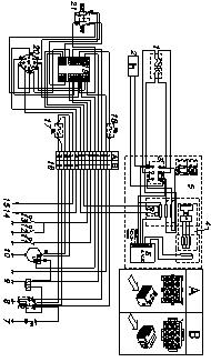
21 IS18.5 Generator Ratings o F) Type: Synchronous, 4-poles, selfexcited Cooling: Air/water (Intercooler water/ air) Voltage: 10-40V Nominal current: A Frequency: 60Hz Max. power: 18.4kW Continuous power: 16.7kW Battery charging output: 10A - 1V Power factor (cos ø): 1 Insulating class: H Voltage stability: ±% Frequency stability: ±.5% IS Generator Ratings (@77 o F) Type: Synchronous, 4-poles, selfexcited Cooling: Air/water (Intercooler water/ air) Voltage: 10-40V Nominal current: A Frequency: 60Hz Max. power: kw Continuous power: 1kW Battery charging output: 10A - 1V Power factor (cos ø): 1 Insulating class: H Voltage stability: ±% Frequency stability: ±.5% IS Engine Model: Yanmar 4TNE94 Type: Diesel / 4-stroke Cylinders: 4 Cylinder block material: Cast iron Bore:.70" Stroke:.94" Displacement : 776cc 1800rpm: 46.4hp RPM: 1800 Compression ratio: 18:1 Combustion system: Direct injection Engine head material: Cast iron Speed governor: Centrifugal mechanical Lubrication system: Forced Oil sump capacity with filter: qt. Engine stop system: Fuel solenoid Fuel pump: Electric Fuel pump discharge:.6' Fuel full load: 1.98gal/hr Air combustion requirment: 79cfm Starting battery: 80Ah - 1V Battery charger: 15Ah - 1V Max. inclination: 0 Starter:.kW - 1V 6.1 References for wiring diagrams References for the wiring diagram (fig. 11) 1 Circuit breaker Hour meter Terminal clamp 4 Rotor 5 Stator 6 Electronic voltage adjuster 7 Battery 8 Starter motor 9 Stop solinoid 10 Battery charger DC alternator 11 Pressure switch 1 High water temperature switch 1 High cooling liquid temperature switch 14 Oil pressure sensor 15 Cooling water temperature sensor 16 Connector 17 Battery charger current circuit breaker 18 Low voltage system circuit breaker 19 Engine overload protection module 0 Remote control panel connection 1 Start and stop button 1
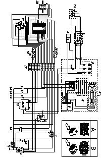
22 References for the wiring diagram (fig. 1) 1 Circuit breaker Hour meter Terminal clamp 4 Rotor 5 Stator 6 Electronic voltage adjuster 7 Battery 8 Starter motor 9 Stop solenoid 10 Battery charger DC alternator 11 Pressure switch 1 High water temperature switch 1 High cooling liquid temperature switch 14 Oil pressure sensor 15 Cooling water temperature sensor 16 Connector 17 Battery charger current circuit breaker 18 Low voltage system circuit breaker 19 Engine overload protection module 0 Remote control panel connection 1 Start and stop button Terminal board References for the wiring diagram (fig. 14) 1 Circuit breaker Hour meter Terminal clamp 4 Rotor 5 Stator 6 Electronic voltage adjuster 7 Starting relay 8 Battery charger supplying relay 9 Starter 10 Battery 11 Negative pole 1 Stop solenoid 1 Battery charger 14 Pressure switch 15 High water temperature switch 16 High cooling liquid temperature switch 17 Connector 18 Battery charger current circuit breaker 19 Low voltage system circuit breaker 0 Remote control panel connection 1 Engine overload protection module Start and stop button Terminal board References for the wiring diagram (fig. 1) 1 Circuit breaker Hour meter Terminal clamp 4 Rotor 5 Stator 6 Electronic voltage adjuster 7 Battery 8 Starter motor 9 Stop electromagnet 10 Battery charger DC alternator 11 Pressure switch 1 High water temperature switch 1 High cooling liquid temperature switch 14 Oil pressure sensor 15 Cooling water temperature sensor 16 Connector 17 Battery charger current circuit breaker 18 Low voltage system circuit breaker 19 Engine overload protection module 0 Remote control panel connection 1 Start and stop button References for the wiring diagram (fig. 15) gen-set wirh insulated poles 1 Circuit breaker Hour meter Terminal clamp 4 Rotor 5 Stator 6 Electronic voltage adjuster 7 Battery 8 Starter motor 9 Stop solenoid 10 Battery charger DC alternator 11 Pressure switch 1 High water temperature switch 1 High cooling liquid temperature switch 14 Oil pressure sensor 15 Cooling water temperature sensor 16 Connector 17 Relay 18 Low voltage system circuit breaker 19 Engine overload protection module 0 Remote control panel connection 1 Start and stop button Relay Relay
IS7.6 INSTALLATION MANUAL
 IS7.6 INSTALLATION MANUAL #12501 MIN. 13.5" 1" 1" 29-7/8" 3" 14-7/8" 3" 20-7/8" 29-7/8" 24-5/8" Fig. 1 1 2 Fig. 2 Fig. 3 MAX. 80" MIN. 12" IS7.6 MIN. 8" Fig. 4 2 MIN. 6" MIN. 13.5" MIN. 12" MIN. 6" MIN.
IS 11 IS 13.5 IS 15 IS 18.5 IS 21 IS 23 INSTALLATION MANUAL. 50 Hz. 60 Hz. 50 Hz. 60 Hz. 50 Hz. 60 Hz. COD i
 IS IS 3.5 IS 5 IS 8.5 IS IS 3 50 Hz 60 Hz 50 Hz 60 Hz 50 Hz 60 Hz INSTALLATION MANUAL COD. 4098i Fig. 3 4 Fig. Nomefile: miis5us.pm5 Data di aggiornamento: 06/0/98 Redatto: Service Paolucci - - Fig. 3
AIR-COOLED DIESEL GENERATOR OWNERʼS MANUAL. This manual contains important safety information. TDG2500E TDGW7000E TDG7000SE TDG4500E
 AIR-COOLED DIESEL GENERATOR OWNERʼS MANUAL This manual contains important safety information. TDG2500E TDGW7000E TDG7000SE TDG4500E TDG8000-3 TDG7000SE-3 TDG7000E TDG8000E TDGW7000SE TDG7000E3 TDGW8000E
1100W PORTABLE GENERATOR
 1100W PORTABLE GENERATOR MODEL NO: G1200 PART NO: 8010110 OPERATION & MAINTENANCE INSTRUCTIONS LS0312 INTRODUCTION Thank you for purchasing this CLARKE 1100W Portable Generator. Before attempting to use
English N Reference : Date : 12/2007 Version : A. This photograph does not necessarily represent the engine
 English N4.00 Reference : 970 34 343 Date : 2/2007 Version : A This photograph does not necessarily represent the engine N4.00 - Owner s manual Technical characteristics Engine specifications Cycle 4 strokes,
MP V 8A Electronic Smart Charger. Instruction and Information Manual
 MP7428 12V 8A Electronic Smart Charger Instruction and Information Manual In order to ensure correct and safe usage of your battery charger, you should read these instructions carefully. Please retain
1200W INVERTER GENERATOR
 1200W INVERTER GENERATOR MODEL NO: IG1200 PART NO: 8877070 OPERATION & MAINTENANCE INSTRUCTIONS LS0117 INTRODUCTION Thank you for purchasing this CLARKE 1200W Inverter Generator. Before attempting to use
Maintenance of Pleasureboat Diesel Engine GM Series
 Maintenance of Pleasureboat Diesel Engine GM Series.Safety Precaution for Inspection )Battery Fluid Battery fluid is diluted sulfuric acid. It can blind you if it gets in your eyes, or burn your skin.
LDG6000SA DIESEL GENERATOR OWNERS MANUAL
 LDG6000SA DIESEL GENERATOR OWNERS MANUAL BEFORE OPERATING THIS EQUIPMENT PLEASE READ THESE INSTRUCTIONS CAREFULLY Preface Thank-you for purchasing this generator. This operation manual contains information
HIGH FREQUENCY AUTOMATIC BATTERY CHARGER
 HIGH FREQUENCY AUTOMATIC BATTERY CHARGER MODEL NO: HFBC12 PART NO: 6267000 OPERATION & MAINTENANCE INSTRUCTIONS LS0814 INTRODUCTION Thank you for purchasing this CLARKE High Frequency Automatic Battery
English N4.85. Reference : Date : 12/2007 Version : A. This photograph does not necessarily represent the engine
 English N4.85 : 970 34 956 Date : 2/2007 Version : A This photograph does not necessarily represent the engine N4.85 - Owner s manual Technical characteristics Engine specifications Cycle 4 strokes, Diesel
SECTION 3.00 WARNING WARNING ENGINE STARTUP AND SHUTDOWN PRESTART INSPECTION
 SECTION 3.00 ENGINE STARTUP AND SHUTDOWN PRESTART INSPECTION Be sure that the clutch, circuit breaker, or other main power transmission device is disconnected. Generators develop voltage as soon as the
TD-POWER marine. TDME series marine diesel engine Operation manual. Jiangyan Xinyang Machine-building Co., Ltd
 TD-POWER marine 2003/44/EC APPROVED TDME series marine diesel engine Operation manual Jiangyan Xinyang Machine-building Co., Ltd East Xingjiang Road Private Economic Center, jiangyan City, Jiangsu, China
720W PORTABLE GENERATOR
 720W PORTABLE GENERATOR MODEL NO: G720 PART NO: 8857800 OPERATION & MAINTENANCE INSTRUCTIONS LS0214 INTRODUCTION Thank you for purchasing this CLARKE 720W Portable Generator Before attempting to use this
Electric Trolling Motor
 Electric Trolling Motor L Series User s Manual Please read and retain this manual before using product REACH RoHS TABLE OF CONTENTS Contents GENERAL INFORMATION 4 SPECIFICATIONS 4 WIRING AND BATTERY RECOMMENDATIONS
INSTALLATION & OPERATION MANUAL
 INSTALLATION & OPERATION MANUAL PRE-ASSEMBLED PRIMARY & BATTERY BACK-UP SUMP PUMP SYSTEM 5030CVSPBUSS, 5033CVSPBUSS www.aymcdonald.com A.Y. McDonald BBU Manual Revised 8-13 3210-479 Rev. A 12 This pump
VADA - V75-S PRODUCT OVERVIEW CONSTRUCTION USAGE LIMITATIONS MOTOR WARRANTY
 PRODUCT OVERVIEW The VADA V75-S submersible pumps are suitable for installation in traditional wells, water deposits, collection tanks, clear watercourses, lakes etc. The V75-S provides a hydraulic system
WARNING: Read these instructions before using the machine GENERATOR MODEL NO: IG3500F PART NO: OPERATION & MAINTENANCE INSTRUCTIONS
 WARNING: Read these instructions before using the machine GENERATOR MODEL NO: IG3500F PART NO: 8877100 OPERATION & MAINTENANCE INSTRUCTIONS ORIGINAL INSTRUCTIONS LS0217 INTRODUCTION Thank you for purchasing
5 IN 1 JUMP START OPERATION & MAINTENANCE INSTRUCTIONS MODEL NO: JS5IN1 PART NO: LS0810
 5 IN 1 JUMP START MODEL NO: JS5IN1 PART NO: 6240005 OPERATION & MAINTENANCE INSTRUCTIONS LS0810 INTRODUCTION Thank you for purchasing this CLARKE product. Before attempting to use this product, please
GENERATOR MODEL NO: FG3000 OPERATION & MAINTENANCE INSTRUCTIONS PART NO: LS0609
 GENERATOR MODEL NO: FG3000 PART NO: 8857700 OPERATION & MAINTENANCE INSTRUCTIONS LS0609 INTRODUCTION Thank you for purchasing this CLARKE Generator. Before attempting to use this product, please read this
Vehicle battery BATTERY WARNING SYMBOLS BATTERY CARE
 Vehicle battery BATTERY WARNING SYMBOLS On the battery label, the warning signs are as follows: BATTERY CARE No smoking, no naked flames, no sparks. The battery may emit explosive gas. Keep away from children
HOT WASHER MODEL NO: KING 125 OPERATION & MAINTENANCE INSTRUCTIONS PART NO: LS1009
 HOT WASHER MODEL NO: KING 125 PART NO: 7320170 OPERATION & MAINTENANCE INSTRUCTIONS LS1009 INTRODUCTION Thank you for purchasing this Hot Washer. This machine is a portable, high pressure power washer,
GENERATOR MODEL NO: FG3005 OPERATION & MAINTENANCE INSTRUCTIONS PART NO: LS0413
 GENERATOR MODEL NO: FG3005 PART NO: 8857707 OPERATION & MAINTENANCE INSTRUCTIONS LS0413 INTRODUCTION Thank you for purchasing this CLARKE Generator. Before attempting to use this product, please read this
M-3025CB-AV Fuel Pump
 SAVE THESE INSTRUCTIONS M-3025CB-AV Fuel Pump Owner s Manual TABLE OF CONTENTS General Information... 2 Safety Instructions... 2 Installation... 3 Operation... 4 Maintenance... 4 Repair... 5 Troubleshooting...
4.2 Component Identification
 Digital Control Panels Deep Sea Electronics 5220 4.1 General 4.2 Component Identification 4.3 The YML5220 Controller 4.4 Description of Controls 4.5 Navigation 4.5.1 General Navigation 4.5.2 The Event
PNEUMATIC PUMP Series
 PNEUMATIC PUMP Series 3103... User and Maintenance Manual Original text translation TABLE OF CONTENTS 1. INTRODUCTION 2. GENERAL DESCRIPTION 3. PRODUCT-MACHINE IDENTIFICATION 4. TECHNICAL CHARACTERISTICS
GENERATOR MODEL NO: FG2500 OPERATION & MAINTENANCE INSTRUCTIONS PART NO: LS0114
 GENERATOR MODEL NO: FG2500 PART NO: 8857727 OPERATION & MAINTENANCE INSTRUCTIONS LS0114 INTRODUCTION Thank you for purchasing this CLARKE Generator. Before attempting to use this product, please read this
TC Series Cooling Systems
 TC Series Cooling Systems Table of Contents Table of Contents...1 List of Figures...1 Safety...2 Introduction...2 General Specifications...2 Types of Coolant...2 Routine Maintenance...2 Surge Tank Coolant
IMPORTANT INFORMATION
 Table of Contents IMPORTANT INFORMATION Section 1B - Maintenance MAINTENANCE 1 B Specifications........................... 1B-1 Special Tools........................... 1B-2 Mercury/Quicksilver Lubricants
5.5KVA GENERATOR MODEL NO: PG6500DVES OPERATION & MAINTENANCE INSTRUCTIONS PART NO: LS0616
 5.5KVA GENERATOR MODEL NO: PG6500DVES PART NO: 8857810 OPERATION & MAINTENANCE INSTRUCTIONS LS0616 INTRODUCTION Thank you for purchasing this CLARKE 5.5KVA Generator. Before attempting to use this product,
Car Battery Charger Instructions for Use
 BATTERY CHARGER 12Volt 4Amp FOR INDOOR USE ONLY Power Details: Input: 230-240Vac; 50Hz; 52W Output: 12V DC; 2.8A Maximum Charge Rate: 4A RMS Read these instructions before operating this car battery charger
SBS Manual for the specialised craftsman. Filling and flushing station. Connection Operation. en Manual
 SBS 2000 Filling and flushing station Manual for the specialised craftsman Connection Operation Thank you for buying this RESOL product. Please read this manual carefully to get the best performance from
6 Litre Oil-Less Air Compressor
 Operator s Manual 6 Litre Oil-Less Air Compressor WARNING! Before using this appliance, read the Operator s manual and follow all its safety rules and instructions. SPECIFICATION HWKAC1 1.1 kw / 1.5 HP
6L Oil-less Air Compressor 53103
 6L Oil-less Air Compressor 53103 Operating Instructions Please read and save these instructions before attempting to assemble, install, operate or maintain the product. Protect yourself and others by observing
P773-2 For Model: M773LW2 PARTS MANUAL. Marine Generators Marine Diesel Engines Land-Based Generators
 P773-2 For Model: M773LW2 PARTS MANUAL Marine Generators Marine Diesel Engines Land-Based Generators CALIFORNIA Proposition 65 Warning: Diesel engine exhaust and some of its constituents are known to the
SECTION 6 2 SERVICE PROCEDURES AND SPECIFICATIONS. Engine. Specifications
 SERVICE PROCEDURES AND SPECIFICATIONS Engine SECTION 6 2 Specifications........................................... 170 Fuel.................................................... 172 Facts about engine oil
Printed: Doc-Nr: PUB / / 000 / 00
 ORIGINAL OPERATING INSTRUCTIONS Hilti HTE-P 33 dispenser It is essential that the operating instructions are read before the tool is operated for the first time. Always keep these operating instructions
Cooling System. Table of Contents
 Sub-Headings Safety 2 s 2 Cautions 2 Notes 2 Introduction 2 General Specifications 2 Engine 2 Coolant 2 Routine Maintenance 2 Hose Connections 4 Radiator, Charge Air and Heater Cores 4 Cooling System Leaks
Medium and high pressure pumps
 Screw pumps Medium and high pressure pumps Installation and Start-up Instruction This instruction is valid for all standard high pressure pumps: E4, D4 and D6 Contents Page Pump identification 2 Installation
3KVA DUAL VOLTAGE GENERATOR MODEL NO: PG3800DV
 3KVA DUAL VOLTAGE GENERATOR MODEL NO: PG3800DV PART NO: 8857815 OPERATION & MAINTENANCE INSTRUCTIONS LS1016 INTRODUCTION Thank you for purchasing this CLARKE 3KVA Dual Voltage Generator. Before attempting
SUBMERSIBLE WATER PUMP
 SUBMERSIBLE WATER PUMP MODEL NO: CSV1A, CSV2A PART NO: 7230582, 7230602 OPERATION & MAINTENANCE INSTRUCTIONS ORIGINAL INSTRUCTIONS 05/14 iss 4 INTRODUCTION Thank you for purchasing this CLARKE Submersible
AUTOMATIC BATTERY CHARGER AUTOMATISCHES BATTERIELADEGERÄT CHARGEUR DE BATTERIE AUTOMATIQUE AUTOMATISCHE ACCULADER 12A RMS (8A DC) MCH12A
 MCH12A") AUTOMATIC BATTERY CHARGER AUTOMATISCHES BATTERIELADEGERÄT CHARGEUR DE BATTERIE AUTOMATIQUE AUTOMATISCHE ACCULADER 12A RMS (8A DC) MCH12A Suitable for all type of 12V lead acid, sealed, leisure and gel
AUTOMATIC BATTERY CHARGER AUTOMATISCHES BATTERIELADEGERÄT CHARGEUR DE BATTERIE AUTOMATIQUE AUTOMATISCHE ACCULADER 12A RMS (8A DC) MCH12A Suitable for all type of 12V lead acid, sealed, leisure and gel
Instruction manual. Marine Diesel engine N C MU_N4.38_ _ENG
 Instruction manual Marine Diesel engine N4.38 13111-C MU_N4.38_97031344_ENG Technical characteristics ENGINE SPECIFICTIONS N4.38 Cycle 4 strokes, Diesel Max. power - kw (hp)* 7.6 (37.5) Number of cylinders
OPERATION & MAINTENANCE INSTRUCTIONS
 750W SUBMERSIBLE PUMP WITH BUILT-IN FLOAT SWITCH MODEL NO: PSV5A PART NO: 7236046 OPERATION & MAINTENANCE INSTRUCTIONS ORIGINAL INSTRUCTIONS LS0917 iss 3 INTRODUCTION Thank you for purchasing this CLARKE
Installation Operation Parts
 OWNER S MANUAL BATTERY BACKUP SUMP Installation Operation Parts For further operating, installation or maintenance assistance, Call 98-8-05 PRINTED IN U.S.A. M-8 (/9) RULES FOR SAFE INSTALLATION AND OPERATION
Routine Compressor Maintenance
 Establishing a regular, well-organized maintenance program and strictly following it is critical to maintaining the performance of a compressed air system. One person should be given the responsibility
Air Compressor. Operating & Maintenance Instructions 1110 ENGINE DRIVEN - 1 -
 Air Compressor ENGINE DRIVEN Operating & Maintenance Instructions 1110-1 - Read these safety instructions before using the equipment. INTRODUCTION Thank you for purchasing this Clarke portable compressor.
4 Stroke Diesel. Oil type SAE 15 W40/E 3
 MARCH 2006 TECHNICAL DATA 2.33 GENERAL SPECIFICATIONS Cycle Air supply Injection 4 Stroke Diesel naturally aspirated direct Number of cylinders 4 in line 6 in line Bore mm 104 Stroke mm 132 Total displacement
Instruction Manual. Maximum Operating Pressure 510 bar
 Single Speed Diesel Power Unit Model HPD11 Maximum Operating Pressure 510 bar ABSOLUTE EQUIPMENT PTY LTD 2/186 Granite Street, GEEBUNG QLD 4034 Australia sales@absoluteequipment.com.au Phone: +61 7 3865
3.25 Ton Heavy Duty Floor Jack
 Please dispose of packaging for the product in a responsible manner. It is suitable for recycling. Help to protect the environment, take the packaging to the local amenity tip and place into the appropriate
IMPORTANT INSTRUCTIONS FOR OPERATION & MAINTENANCE OF
 IMPORTANT INSTRUCTIONS FOR OPERATION & MAINTENANCE OF CONVEYORS EASIKIT 300 EASIKIT 450 EASIKIT 600, 900, 1200 & 1500 The manufacturer does not accept responsibility for any loss, damage to other equipment,
CORDLESS COMPRESSOR WITH SPOTLIGHT + JUMP START
 CSS1 - Spotlight compressor (08-0540-2).book Page 1 Thursday, June 17, 2010 10:26 AM CORDLESS COMPRESSOR WITH SPOTLIGHT + JUMP START MODEL NO: CSS1 PART NO: 6240055 OPERATION & MAINTENANCE INSTRUCTIONS
Instructions for use Attention
 Instructions for use 1. Attention... 45 2. 2.1. 2.2. 2.3. 2.4. 2.5. 2.6. General information Description Voltmeter Alternator Testing LED Clamp Recharge the Booster using the AC 230V or 110V / DC 12V charger
INSTRUCTIONS FOR: VACUUM TESTER AND BRAKE BLEEDING KIT
 INSTRUCTIONS FOR: VACUUM TESTER AND BRAKE BLEEDING KIT MODEL: VS402 Thank you for purchasing a Sealey product. Manufactured to a high standard this product will, if used according to these instructions
Installation and operating instructions. Solar charge controller MPPT 10 A / 20 A Z Z
 Installation and operating instructions Solar charge controller MPPT 10 A / 20 A EN 1 Contents 1. About these instructions... 3 1.1 Applicability... 3 1.2 Users... 3 1.3 Description of symbols... 3 2.
Engine oil. Introduction. Warning and indicator lights WARNING
 Engine oil Introduction In this section you ll find information about: Warning and indicator lights Engine oil specifications Engine oil capacities Checking the engine oil level and adding oil Engine oil
QUOTATION BLADE 7 LX. Product code GEAL6S2BAA
 1 of 10 Mattei rotary vane compressors are the result of 90 years of investments in research and development to improve performance and lessen the impact on the environment. Designed for industrial continuous
SAFETY AND OPERATING MANUAL
 SAFETY AND OPERATING MANUAL COLD WATER PETROL WATER BLASTERS Read Safety & Operating Instructions Before Commencing Operation THESE INSTRUCTIONS MUST BE READ AND ADHERED TO BEFORE OPERATING THIS MACHINE.
SPECIFICATIONS SUBJECT TO CHANGE WITHOUT NOTICE
 PREFACE The following manual is only a guide to assist you and is not a complete or comprehensive manual of all aspects of maintaining and repairing your generator. The equipment you have purchased is
JUMPSTART MODEL NO: JS1000, JS1010 & JS1224 OPERATING & MAINTENANCE INSTRUCTIONS PART NO: , & GC0514
 JUMPSTART MODEL NO: JS1000, JS1010 & JS1224 PART NO: 6240040, 6240035 & 6240045 OPERATING & MAINTENANCE INSTRUCTIONS GC0514 INTRODUCTION Thank you for purchasing this CLARKE Jumpstart. Before attempting
VS403 INSTRUCTIONS FOR: VACUUM AND PRESSURE TEST / BRAKE BLEEDING UNIT MODEL: SAFETY INSTRUCTIONS INTRODUCTION & CONTENTS. fig.1
 INSTRUCTIONS FOR: VACUUM AND PRESSURE TEST / BRAKE BLEEDING UNIT MODEL: VS403 Thank you for purchasing a Sealey product. Manufactured to a high standard this product will, if used according to these instructions
BATTERY CHARGER-STARTER
 BATTERY CHARGER-STARTER MODEL NO: WBC240 & WBC400 PART NO: 6261505 & 6261515 OPERATION & MAINTENANCE INSTRUCTIONS GC0116 INTRODUCTION Thank you for purchasing this CLARKE Battery Charger/Starter. Please
SECTION 6 2 SERVICE PROCEDURES AND SPECIFICATIONS. Engine. Specifications
 SERVICE PROCEDURES AND SPECIFICATIONS Engine SECTION 6 2 Specifications........................................... 162 Fuel.................................................... 164 Facts about engine oil
CHAPTER 20: Operation and maintenance
 Pressurized Irrigation Techniques 20.1 CHAPTER 20: Operation and maintenance INTRODUCTION The efficient operation of an irrigation system depends mainly on the ability of the farmer to make the best use
VADA - V60-J PRODUCT OVERVIEW CONSTRUCTION MOTOR USAGE LIMITATIONS WARRANTY
 PRODUCT OVERVIEW The VADA series of self priming jet pumps combine the functional benefits of centrifugal pumps and the practical and qualitative benefits of self-priming pumps. The Venturi system the
Generator Set. CP Range. Operating & Maintenance Instructions 0702
 Generator Set CP Range Operating & Maintenance Instructions 0702 Read these safety instructions before using the equipment. Introduction Thank you for purchasing this Clarke portable Generator set. The
250W PUDDLE PUMP WITH AUTO SENSOR MODEL NO: PSP105
 250W PUDDLE PUMP WITH AUTO SENSOR MODEL NO: PSP105 PART NO: 7230693 OPERATION & MAINTENANCE INSTRUCTIONS ORIGINAL INSTRUCTIONS LS0917 -- iss 3 INTRODUCTION Thank you for purchasing this CLARKE 250W Puddle
EC MACHINE DIRECTIVE COMPLIANCE DECLARATION
 EC MACHINE DIRECTIVE COMPLIANCE DECLARATION (DIRECTIVE 89/392 EEC, APPENDIX II, PART B) Manufacturer: FAAC S.p.A. Address: Via Benini, 1 40069 - Zola Predosa BOLOGNA - ITALY Hereby declares that: the 770
OPERATION MANUAL BATTERY CHARGER DFC-10P DFC-50P DFC-450P DFC-650P
 OPERATION MANUAL BATTERY CHARGER DFC-10P DFC-50P DFC-450P DFC-650P 1: INTRODUCTION This machine is designed to charge lead-acid storage batteries suitable for commercial and passenger vehicles, motorcycles,
Instruction manual. Marine Diesel engine N C MU_N4.115_ _ENG
 Instruction manual Marine Diesel engine N4.115 13111-C MU_N4.115_97031314_ENG Technical characteristics ENGINE SPECIFICTIONS N4.115 Cycle 4 strokes Diesel, 4 valves per cylinder Max. power - kw (hp)* 84.6
Installation instruction
 Installation instruction Intercalated generator CIC Reference : 60 300 143 09/2008 Complete 12V or 24V system Wet or gel battery 1 Installation instructions - Intercalated generator Table of contents Safety
VERTICAL MULTI-STAGES CENTRIFUGAL PUMPS
 Installation and Operating Instructions VERTICAL MULTI-STAGES CENTRIFUGAL PUMPS Models 1, 3, 5, 10, 15, 20, 32, 45, 64, 90, 120, 150 1. Model numbering and nameplate format 1.1 Model numbering Example:
Preventive maintenance 4
 00 Series Preventive maintenance Preventive maintenance periods Use the procedures in this chapter to maintain your engine in accordance with the preventive maintenance schedule. Check the periods given
STEP-BY-STEP INSTALLATION GUIDE
 Battery Backup System STEP-BY-STEP INSTALLATION GUIDE Operating Instructions & Parts Manual ESP25 Please read and save these instructions. Read carefully before attempting to assemble, install, operate
OPERATION & MAINTENANCE INSTRUCTIONS
 400W SUBMERSIBLE PUMP WITH FOLDING BASE AND FLOAT SWITCH MODEL NO: PSV6A PART NO: 7230695 OPERATION & MAINTENANCE INSTRUCTIONS LS0315 INTRODUCTION Thank you for purchasing this CLARKE 400W Submersible
Exhaust Alert Installation & Operating Instructions THE SCIENCE OF SILENCE. Exhaust Alert Operating & Fitting Instructions 1
 Exhaust Alert Installation & Operating Instructions THE SCIENCE OF SILENCE Exhaust Alert Operating & Fitting Instructions 1 Contents Exhaust Alert Fitting Instructions Section Page 1 Introduction 2 1.1
VERTICAL MULTI-STAGE CENTRIFUGAL PUMPS
 Installation and Operating Instructions VERTICAL MULTI-STAGE CENTRIFUGAL PUMPS Models 1, 3, 5, 10, 15, 20, 32, 45, 64, 90 1. Model numbering and nameplate format 1.1 Model numbering Example: SBI / SBN
SUBMERSIBLE PUMP HSE RANGE
 SUBMERSIBLE PUMP HSE RANGE OPERATION & MAINTENANCE INSTRUCTIONS 0806 SPECIFICATIONS Model No. HSE120* HSE200 HSE300*/ HSE360*/ HSEC400* HSE301 HSE361 Outlet Dia. (mm/inches) 32/1-1/4 38/1-1/2 50/2 50/2
Original Language Version VS4021 Issue: 1-08/06/12
 1. safety instructions Keep this product in good working order and condition, take immediate action to repair or replace damaged parts. Use approved parts only. Unapproved parts will invalidate the warranty.
General operating manual for assembly, commissioning and maintenance of valves and hydraulic manifolds
 for assembly, commissioning and maintenance of valves and hydraulic manifolds 110210_general_operating_manual 07.2018 Table of contents Contents Page Important information 2 Important safety instructions
SUBMERSIBLE DIRTY WATER PUMP
 FOR USE WITH A 110V SUPPLY ONLY SUBMERSIBLE DIRTY WATER PUMP MODEL NO: DWP210A PART NO: 7230102 OPERATION & MAINTENANCE INSTRUCTIONS LS0115 INTRODUCTION Thank you for purchasing this CLARKE Submersible
USER MANUAL. Uninterruptible Power Supply Line-interactive VCL Series UPS VA
 USER MANUAL Uninterruptible Power Supply Line-interactive VCL Series UPS 800 1100 2000 3000 VA GE Consumer & Industrial SA General Electric Company CH 6595 Riazzino (Locarno) Switzerland T +41 (0)91 /
SP6. Automatic Battery Charger. Model
 Model SP6 Automatic Battery Charger OWNERS MANUAL PLEASE SAVE THIS OWNERS MANUAL AND READ BEFORE EACH USE. This manual will explain how to use the charger safely and effectively. Please read and follow
Instructions for use
 Congratulations, you are now the owner of a Battery Booster PROPULSTATION, the only jump starter with a docking station! Chosen by the professionals all over the world for its power and reliability, it
MODEL CJ-95 CoilJet Portable HVAC Coil Cleaning System
 MODEL CJ-95 CoilJet Portable HVAC Coil Cleaning System OPERATING AND MAINTENANCE INSTRUCTIONS CJ-95 Manual 2009 All Rights Reserved 07/2009 Table of Contents Warranty... 1 Important Safety Instructions...
Advanced EasyStart Troubleshooting
 Advanced EasyStart Troubleshooting EasyStart is designed for excellent reliability and durability. Every EasyStart is tested on a compressor before it leaves Micro-Air to ensure it will work when delivered.
Bombardier Challenger Auxiliary Power Unit
 GENERAL A Honeywell 36 150(CL) constant-speed gas turbine auxiliary power unit (APU) is installed within a fire-resistant compartment in the aft equipment bay. The APU drives a generator, providing AC
VECTOR SERIES USE AND MAINTENANCE USO E MANUTENZIONE UTILISATION ET ENTRETIEN BETRIEB UND WARTUNG USO Y MANTENIMIENTO MARINE ENGINES
 USE AND MAINTENANCE USO E MANUTENZIONE UTILISATION ET ENTRETIEN BETRIEB UND WARTUNG USO Y MANTENIMIENTO VECTOR SERIES MARINE ENGINES Publication edited by Marketing - Adv. & Promotion Print L31900014-03/06
ELECTRIC HOIST MODEL NO: CH2500B, CH4000B OPERATION & MAINTENANCE INSTRUCTIONS PART NO: , LS1010
 ELECTRIC HOIST MODEL NO: CH2500B, CH4000B PART NO: 7630386, 7630391 OPERATION & MAINTENANCE INSTRUCTIONS LS1010 INTRODUCTION Thank you for purchasing this CLARKE Electric Hoist. Before attempting to use
Table of Contents. Safety symbols... 3 Assembly 6. Operation Maintenance Troubleshooting 11. Storage. 12. Notes. 13
 Table of Contents Safety symbols... 3 Assembly 6 Operation... 8 Maintenance... 10 Troubleshooting 11 Storage. 12 Notes. 13 2 Safety Information Attention; this machine can be dangerous! All operators should
Operating and Installation Instructions Diaphragm Vacuum Pumps and Compressors
 Operating and Installation Instructions Diaphragm Vacuum Pumps and Compressors Type range: UN813.3ANI UN813.4ANI UN813.3ANDCB UN813.4ANDCB UN813.5ANI Fig. 1: UN813.3ANI Fig. 2: UN813.4ANI You have selected
8. Remote Control Panel P4 Control
 8. Remote Control Panel P4 Control Art Nr. 0000522 Bez. Remote Control Panel P4 Control Tabelle 1: Dokument Hardware Software Aktuell: R03 V1.00 -------------------------- Ersetzt: R02.1 V1.00 --------------------------
L-SERIES PUMPS. Operating Manual. Includes Pumps: L-305 L PONDS
 L-SERIES PUMPS Operating Manual Includes Pumps: L-305 L-310 1-877-80-PONDS www.atlanticwatergardens.com Introduction Thank you for selecting the TidalWave L-305/L-310 series pumps. Before using this pump
Contents INTRODUCTION... 2 CHECK YOU HAVE RECEIVED... 4 WHAT YOU WILL NEED...4 TECHNICAL CHARACTERISTICS...5 WIRING DIAGRAMES...6 CABLES...
 Contents Page INTRODUCTION... 2 CHECK YOU HAVE RECEIVED... 4 WHAT YOU WILL NEED...4 TECHNICAL CHARACTERISTICS...5 WIRING DIAGRAMES...6 CABLES...6 BATTERY...7 CHARGE CONTROLLER...8 FUSE...8 TOWERS...8 INSTALLATIONS...9
LS100L Battery-powered Punch Driver
 OPERATION MANUAL Serial Number GATOR LS100L Battery-powered Driver Read and understand all of the instructions and safety information in this manual before operating or servicing this tool. Register this
3 Ton Trolley Jack. Please read and fully understand the instructions in this manual before operation. Keep this manual safe for future reference.
 Please dispose of packaging for the product in a responsible manner. It is suitable for recycling. Help to protect the environment, take the packaging to the local amenity tip and place into the appropriate
GENERATOR MODEL NO: DG6000DVES OPERATION & MAINTENANCE INSTRUCTIONS PART NO: LS1216
 GENERATOR MODEL NO: DG6000DVES PART NO: 8675000 OPERATION & MAINTENANCE INSTRUCTIONS LS1216 INTRODUCTION Thank you for purchasing this CLARKE Generator. Before attempting to use this product, please read
Specialty Pond Sprayer
 Specialty Pond Sprayer 2.75 Gallon Capacity Sprayer Installation & Maintenance Manual (Item # 580121) 1 Year Warranty Specialty Pond Sprayer 2.75 Gallon Capacity Sprayer Thank you for purchasing this compression
Starting up hydraulic systems
 General / Installation A hydraulic system that operates economically, safely, and trouble-free requires careful planning, as well as proper installation and start-up. Conscientious maintenance has a considerable
Models: SP3, SPSS3 Automatic Battery Charger
 OWNERS MANUAL Models: SP3, SPSS3 Automatic Battery Charger PLEASE SAVE THIS OWNERS MANUAL AND READ BEFORE EACH USE. This manual will explain how to use the charger safely and effectively. Please read and