Burners. Ribbon linear flame burners AB & ABM (E3010 rev /11/2017)
|
|
|
- Silvia Roberts
- 5 years ago
- Views:
Transcription


1 Burners Ribbon linear flame burners AB & ABM (E3010 rev /11/2017)
2 GENERAL WARNINGS: DISPOSAL: ¾ All installation, maintenance, ignition and setting must be performed by qualified staff, respecting the norms present at the time and place of the installation. ¾ To avoid damage to people and things, it is essential to observe all the points indicated in this handbook. The reported indications do not exonerate the Client/User from observing general or specific laws concerning accidents and environmental safeguarding. ¾ The operator must wear proper DPI clothing (shoes, helmets...) and respect the general safety, prevention and precaution norms. ¾ To avoid the risks of burns or high voltage electrocutaion, the operator must avoid all contact with the burner and its control devices during the ignition phase and while it is running at high temperatures. ¾ All ordinary and extraordinary maintenance must be performed when the system is stopped. ¾ To assure correct and safe use of the combustion plant, it is of extreme importance that the contents of this document be brought to the attention of and be meticulously observed by all personnel in charge of controlling and working the devices. ¾ The functioning of a combustion plant can be dangerous and cause injuries to persons or damage to equipment. Every burner must be provided with certified combustion safety and supervision devices. ¾ The burner must be installed correctly to prevent any type of accidental/undesired heat transmission from the flame to the operator or the equipment. ¾ The performances indicated in this technical document regarding the range of products are a result of experimental tests carried out at ESA-PYRONICS. The tests have been performed using ignition systems, flame detectors and supervisors developed by ESA-PYRO- NICS. The respect of the above mentioned functioning conditions cannot be guaranteed if equipment, which is not present in the ESA-PYRONICS catalogue, is used. To dispose of the product, abide by the local legislations regarding it. Headquarters: Esa S.p.A. Via Enrico Fermi Curno (BG) - Italy Tel Fax esa@esacombustion.it GENERAL NOTES: ¾ In accordance to the internal policy of constant quality improvement, ESA-PYRONICS reserves the right to modify the technical characteristics of the present document at any time and without warning. ¾ It is possible to download technical sheets which have been updated to the latest revision from the website. ¾ The products manufactured by ESA-PYRONICS have been created in conformity to the UNI EN 746-2:2010 Norms: Equipment for industrial thermal process - Part 2: Safety requirements for combustion and the movement and treatment of combustible elements. This norm is in harmony with the Machine Directive 2006/42/CE. It is certified that the products in question respect all the requirements prescribed by the above mentioned Norms and Directives. ¾ Certified in conformity with the UNI EN ISO 9001 Norm by DNV GL. CERTIFICATIONS: The products conform to the requests for the Euroasia market (Russia, Belarus and Kazakhstan). CONTACTS / SERVICE: International Sales: Pyronics International s.a. Zoning Industriel, 4ème rue B-6040 Jumet - Belgium Tel Fax marketing@pyronics.be 2
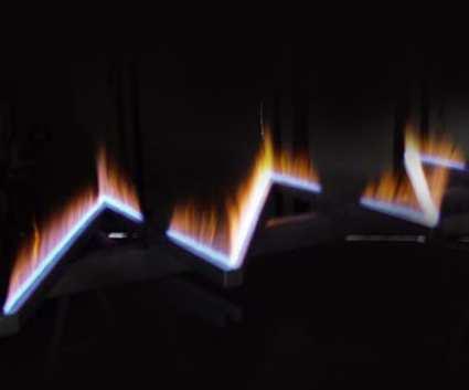
 guarantees excellent flame stability even in combustion chambers with internal recirculation.")
.")
3 The RIBBON AB and ABM series identifies premixed linear flame burners used in low temperature applications for many different thermal industrial requirements. The special shape of the RLF (Ribbon Linear Flame) guarantees excellent flame stability even in combustion chambers with internal recirculation. The AB series burners must be connected to an air/gas mixer that guarantees the correct combustion ratio. The ABM series burners have an air/gas mixer incorporated inside the furnace wall support flange. The mixing flange has a patent for the type of use (n MI2004U000376). The linear flame burners can also have a special design according to the geometric and potential parameters given by the client. APPLICATIONS ¾Environment heating. ¾Furnaces for food cooking. ¾Vial sterilizing machines. ¾Industrial packaging machines. ¾Flame screens. ¾Brazing machines. F3010I04 CHARACTERISTICS GENERAL: ¾Capacity: 10 70kW ¾Temperature limit: 350 C ¾Air pressure to mixer/burner: 50mbar ¾Mixing pressure: mbar ¾Fuel gas: CH4/LPG/Propane ¾Flow ratio: 1 : 5 MATERIAL COMPOSITION: ¾Burner body: Fe / AISI304 / AISI316 ¾Support flange (versions AB): Cast iron G25 / Al ¾Mixing support flange (versions ABM): AI F3010I05 3


4 EXAMPLES OF SPECIAL DESIGN F3010I06 F3010I07 F3010I08 F3010I09 F3010I10 F3010I11 4
5 IGNITION AND DETECTION The AB/ABM RIBBON burner ignition takes place via a high voltage discharge supplied by special electrode. The standard configuration has mono-electrode flame detection. Flame detection can take place, on request, with separate electrode or UV flame detector. All the accessories, concerning ignition and detection are not included in the supply. The adoption of flame control systems is highly recommended in all plants operating at temperatures lower than 750 C (Norm UNI EN746/2). Burner Model Flame Tube Diameter Nominal Capacity [kw] Igniter/Detector 8AB Ø 1 20 ESA WAND 10AB Ø 1.1/4 25 ESA WAND 12AB / 12ABM Ø 1.1/2 30 ESA WAND 16AB / 16ABM Ø 2 40 ESA WAND 20AB / 20ABM Ø 2.1/2 65 ESA WAND CAPACITY PARAMETERS AND FLAME HEIGHT RLF Model RLF idth [mm] Linear Capacity MAX [kw/mt] Flame Height [mm] RLF1 5 mm RLF3 8 mm RLF5 12 mm The table above indicates the maximum capacities produced by an RLF of 1000mm referring to a temperature of about 20 C. The flame heights strongly depend on the Ribbon Linear Flame length. The table below indicates the same capacities referred to various working temperatures. RLF Model Capacities according to the Temperature [kw/mt] Temperature 100 C 150 C 200 C 250 C 300 C 350 C RLF RLF RLF
6 DIAGRAM OF TUBE VOLUME FLOW 10 DN20 DN25 DN32 DN40 Velocity (m/s) DN50 DN Air 20 C P.S.=1 (m 3 /h) G3010I01 To select the correct diameter of the AB burner we advise you to maintain a maximum speed of 5 m/s. 6
7 FLOW SCHEME GAS INLET AB RIBBON BURNER BMS 10 BT 11 HV 2 SV 3 S SV 4 PCV 5 S FCV BID 6 8 BE AIR INLET FCV 1 M MIXER MIX 7 9 GAS INLET ABM RIBBON BURNER BMS 10 BT 11 HV 2 SV 3 S SV 4 S PCV 5 FCV BID 6 8 BE FCV 1 9 M AIR INLET D3010I01 Pos. Description AB ABM Included Not Included Included Not Included 1 Motorized air regulation butterfly valve X X 2 Gas interception ball valve X X 3 Gas interception ball valve X X 4 Gas safety solenoid valve X X 5 Zerogovernor X X 6 Manual air regulation butterfly valve X X 7 Mixer X X 8 Ignition and detection electrode X X 9 Ribbon linear flame burner X X 10 Flame Control X X 11 Ignition Transformer X X 7
8 WARNINGS ¾ The AB & ABM series burners are meant to be used in fixed installations. If mobile installations are required, it is necessary to assess beforehand the possibility of problems caused by the movement of the actual furnace. ¾ The burner ignition must always be carried out at minimum power and then modulating towards the maximum. ¾ Passing from minimum to maximum power and vice versa, must take place gradually and not instananeously. ¾ For all low temperature applications (upto 750 C), burner ignition and fuel gas solenoid valve control must be carried out via a certified burner control device. ¾ To avoid possible damage to the burners, make sure that the blower does not send stale air from combustion products, oils, solvents or other. To prevent these phenomena from taking place, preferibly install the blower or suction duct outside of the establishment and far from exhaust pipes. ¾ Check the corerct connection of the power supply lines after installation. Before turning the burner on, check that the combustion air and fuel gas pressures are correct. ¾ If there are problems with other devices during the burner start-up phase, use the connector with supressor for the connection of the high voltage cabel to the ignition electrode. ¾ Avoid burner ignitions close to each other so as not to overheat the system ignition command devices (solenoid valves and transformers) ¾ Prewash time lapse + first safety time lapse + min. of 5 sec. = time lapse between one ignition and another (however do not attempt more than two ignitions in a time lapse of 30 sec.) ¾ Make sure the power supply is OFF when intervening on the burner and its devices. In case of burner malfunctioning follow the indications given in the present manual in the Maintenance chapter or contact ESA- Pyronics. ¾ Any modification or repair done by thrid parties may compromise the application safety and automatically cause the general warrantee conditions to expire. 8
9 INSTALLATION The AB RIBBON burners can be installed in any position also with flame facing down. To fix the burner in place, flanges with ignition electrodes and flame inspection peepsights can be supplied. For the air and gas pipe connections the use of flexible joints is advised. The connection between burner and mixer must be at least as big as the mixer outlet, do not put place valves or any type of restriction on the piping. The ABM RIBBON burners can be installed in any position even with flame facing down. To fix the burner in place the apporpriate mixing flange that has ignition electrode and flame spy window is used. For the air and gas pipe connections the use of flexible stainless steel joints is advised. During the mounting phase, place the gasket between the burner and the opposite flange of the furnace wall taking care while placing the burner inside the furnace to not damage the flame detection/ignition electrode ceramic (if necessary assemble the electrodes after having fixed th e burner to the furnace wall). MODIFICATION OF FLAME ORIENTATION The ABM series burners have different flame positioning and gas inlet combinations. The position of the gas inlet does not depend on the flame positioning and the possible combinations can also be obtained during the burner assembly, properly rotating the flame tube flange connection (adapting the position of the flame ignition and detection electrode) and inverting the gas components from one side to the other. To obtain excellent results, the following configuration change manouvres should be carried out by properly trained and qualified personnel. The ABM burner can be supplied with three flame configurations: ¾ LF: flame towards the left. ¾ RF: flame towards the right. ¾ UF: flame facing up. To change this configuration act as follows: 1 - Unscrew the four fixing screws (pos. 02) to relesae the flanged flame tube (pos. 01). 2 - Remove the electrode cap (pos.05), the fixing connection (pos.06) and the electrode (pos.04) from the seat. 3 - Rotate the flame tube in the flame position desired. 4 - Fix the flame tube into place, making sure that the gasket is in the correct position (pos.03), screwing on the screws (pos.02). 5 - Place the electrode in the seat corresponding to that of the flame tube, making sure that the electrode gasket is in the correct position. 6 - Fix the electrode into place screwing on bleed nipple again (pos.06). 7 - Place the cap onto the electrode again and check that the discharge ignition is correct D3010I02 9
10 MODIFICATION OF GAS INLET POSITION The ABM burner can be supplied with two gas inlet configurations: ¾LG: gas inlet on the left. ¾RG: gas inlet on the right. To change this orientation act as follows: 1 - Unscrew the grub screw (pos.03) and the gas passage regulation screw (pos.04) 2 - Disassemble the three piece joint (pos.02) and the zero-governor (pos.01) 3 - Swap pos.03 and pos.04 with pos.01 and pos Put the regulation screw pos.04 and the grub screwpos.03 back into the threaded housing. 5 - Screw the three piece joint back on (pos.02 ) with thread seal paste and the zero governor (pos.01) D3010I
11 MOUNTING SHEET - MONO ZONE ABM BURNER LEFT GAS INLET UPPER FLAME RIGHT GAS INLET UPPER FLAME LEFT GAS INLET LEFT FLAME RIGHT GAS INLET LEFT FLAME LEFT GAS INLET RIGHT FLAME RIGHT GAS INLET RIGHT FLAME D3010I
12 MOUNTING SHEET - THREE ZONE ABM BURNER LEFT GAS INLET UPPER FLAME RIGHT GAS INLET UPPER FLAME LEFT GAS INLET LEFT FLAME RIGHT GAS INLET LEFT FLAME LEFT GAS INLET RIGHT FLAME RIGHT GAS INLET RIGHT FLAME D3010I
13 MOUNTING SHEET -PACKAGED ABM BURNER LEFT BLOWER UPPER FLAME LEFT BLOWER RIGHT FLAME RIGHT BLOWER LEFT FLAME RIGHT BLOWER UPPER FLAME D3010I

14 IGNITION - SETTING The operations indicated in the following chapter must be carried out by qualified expert technicians. The nonobservance of the instructions could generate dangerous conditions. 1 - Check that the pressures of the combustion air going out to the blower and the fuel gas supply are within the allowed range. 2 - Regulate the working pressures as well as the intervention pressure of the devices dedicated to the safety of the combustion plant such as: gas pressure reducer, shut off valve, relief valve, pressure switches etc. Simulate the intervention of all the safety devices including the safety overtemperature intervention, checking that the fuel shut off devices act correctly. 3 - Place the motorized air regulation valve in the maximum opening position and regulate the inlet burner or mixer pressures (in nominal conditions the inlet pressure is about 50mbar). 4 - Place the motorized air regulation valve in the minimum opening postion and regluate its opening to obtain (in the burner inlet) the pressures regarding the minimum power (not lower than 2mbar and however to be set with burner running at minimum power). 5 - Activate the burner control device and attmpt several ignitions until the burner ignites. During the ignition attempts, act on the gas regulation valve and, starting from the totally closed position, open it gradually until obtaing burner ignition. 6 - Place the motorized air regulation valve on the maximum opening position and regulate, via the gas regulation valve, the maximum fuel flow, checking, if necessary, the differential pressure created on the calibrated gas flange, if present. Otherwise carry out burner regulation according to the indications in the pictures shown below. 7 - Place the motorized air regulation valve on the minimum opening position and check that the flame is stable. If necessary regulate the gas flow to the minimum position according to the regulation in the pictures below, acting on the zerogovernor spring. 8 - Repeat ignition attempts at minimum burner power, with maximum range, to check the ignition reliabilty and flame stability during regulation. MAX MIN F3010I12 F3010I13 F3010I14 F3010I15 F3010I16 F3010I17 Excess of air Correct ratio Excess of gas 14
15 TRIPPLE ZONE BURNER REGULATION AND IGNITION For the Tripple zone burner ignition, follow the instructions below: 1 - Unscrew the side regulation valves in the completely open position (standard position in which the burners are usually delivered). 2 - Follow the ignition procedure described on the previous page until obtaining a stable flame both at minimum as well as maximum potential. 3 - Adjust the side adjustment screws to change the potential of each individual zone, according to the scheme in the diagram below. To decrease the power of the individual zone, screw on the adjustment screw, to increase the potential, unscrew the adjustment screw. 4 - Once the potentials in the singles have been adjusted, check that: a) Modulating from minimum to maximum potential there are no detachments or flame loss in any of the three zones. b) The correct ignition and flame propagation among the three zones is guaranteed. B3 B2 B1 FIRST ZONE FLAME regulation screw (B1) SECOND ZONE FLAME regulation screw (B2) THIRD FLAME ZONE regulation screw (B3) D3010I
16 GENERAL MAINTENANCE PLAN Operation Type Advised time Notes Pilot burner high voltage electrode connection O annual Check the integrity of the outer plastic and the oxidisation of the internal connector and of the electrode terminal. Ignition / detection electrode O annual Integrity and cleanliness of linear flame tube O E annual N/A Cleanliness of the spy window O annual Burner settings O annual Replace if the kantal terminal is worn or if the ceramic is damaged. Check the Ribbon Linear Flame conditions. If necessary clean with compressed air. Replace the flame tube in case there is damage to the Ribbon Linear Flame that could jeopardize the normal functioning of the burner. Check the integrity of the HT glass and of the gaskets Repeat all the steps in the section IGNI- TION AND SETTING NOTES: Key: O = ordinary / E = extraordinary (*) it is advisable to replace the gaskets on the gas side each time the gas feeding line is disassembled. (**) use high temperature gaskets. 16
17 OVERALL DIMENSIONS - AB (ONLY TUBE) RLF-3/5 15 A = Mixture inlet (optional) ØX B = C Mixture inlet ØX D3010I
18 OVERALL DIMENSIONS - AB ø pipe A Ribbon flame Length = B C 3.5 : 5mm Ø200 FLAME SIDE: LEFT (L) FLAME SIDE: RIGHT 45 (R) 27 No.4 holes ø12 on DBC ø180 ELECTRODE FLAME DIRECTION 115± ELECTRODE FLAME DIRECTION D3010I
19 OVERALL DIMENSIONS - 12ABM 136 "A" "D" FLAME LENGTH = "B" "C" (12) 45 Ø200 Ø11 (4x) Ø Ø1.1/2" 80 2 (Gasket) GAS INLET Rp 3/8" 186±5 AIR INLET Rp 1" D3010I
20 OVERALL DIMENSIONS - 16ABM 128 "A" "D" FLAME LENGTH = "B" "C" (12) 45 Ø200 Ø180 Ø11 (4x) 43 Ø2" 80 2 (Gasket) GAS INLET Rp 3/8" 187±5 AIR INLET Rp 1" D3010I
21 OVERALL DIMENSIONS- 20ABM 129 "D" "A" (MIN.180) FLAME LENGTH = "B" "C" (MIN.50) (12) Ø200 Ø180 Ø11 (4x) 43 Ø2" 84 2 (Gasket) 45 GAS INLET Rp1/2" 260±5 AIR INLET Rp 1.1/4" D3010I
22 OVERALL DIMENSIONS - 12ABM THREE ZONES 142 "D" (12) "A" FLAME LENGTH="B" ="B1" + "B2" + "B3" "C" (MIN. 70) Ø200 Ø11 (4x) Ø Ø1.1/2" 55 2 (Gasket) 148 GAS INLET Rp 3/8" AIR INLET Rp 1" 185±5 D3010I
23 OVERALL DIMENSIONS - 16ABM THREE ZONES 143 "A" "D" FLAME LENGTH "B"="B1"+"B2"+"B3" "C" (MIN. 100) Ø2" Ø200 Ø11 (4x) Ø (Gasket) 148 GAS INLET Rp 3/8" AIR INLET Rp 1" 185±5 D3010I
24 OVERALL DIMENSIONS - 12ABM PACKAGE "D" "A" FLAME LENGHT = "B" "C" Ø1.1/2" 258±2 GAS INLET Rp 3/8" 330±5 213±5 434±5 Ø200 Ø180 Nr.4 holes Ø11 D3010I
25 OVERALL DIMENSIONS - 16ABM PACKAGE "D" "A" FLAME LENGTH = "B" "C" Ø 2" 258±2 GAS INLET Rp 3/8" 330±5 213±5 434±5 Ø200 Ø180 Nr.4 holes Ø11 D3010I
26 ORDERING CODE - BURNER SERIES AB (ONLY TUBE) - AB Tube Diameter ø Flame front C 1 1.1/4 1.1/ / Length mm Material RLF 15 kw / mm 30 kw / mm 50 kw / mm RLF1 RLF3 RLF5 02 Iron AISI 321 AISI 316 Fe Inlet zone A Inlet Length mm Lateral Middle L M Flame front B 04 Length mm 26
27 ORDERING CODE - BURNER SERIES AB - AB Tube Diameter ø Final zone C 1 1.1/4 1.1/ / Length mm Flange type RLF 15 kw / mm 30 kw / mm 50 kw / mm RLF1 RLF3 RLF5 02 Right Left DX SX Inlet zone A Material Length mm Inlet zone B 04 Iron AISI 321 AISI 316 Fe Length mm 27
28 ORDERING CODE - BURNER SERIES ABM - ABM Tube Diameter ø Gas inlet 1.1/ / Right Left RG LG RLF Flame side 15 kw / mm 30 kw / mm 50 kw / mm RLF1 RLF3 RLF5 Left flame Upper flame Right flame LF UF RF Inlet zone A 03 Length mm Length Flame front B mm Iron AISI 321 AISI 316 Material Fe Final zone C 05 Length mm 28
29 ORDERING CODE - BURNER SERIES 3 ZONES - AB - 3 ZONE Tube Diameter ø Final zone C 1.1/ / Length mm RLF Gas inlet 15 kw / mm 30 kw / mm 50 kw / mm RLF1 RLF3 RLF5 Right Left RG LG Length Inlet zone A Flame front B1 mm Left flame Upper flame Right flame Flame side LF UF RF Length B1 mm Flame front B Material Length B2 Flame front B3 mm 06 Iron AISI 321 AISI 316 Fe Length B3 mm 29
Burners. Pilot Heads BTC & BTSA (E3121 rev /04/2018)
") Burners Pilot Heads BTC & BTSA (E3121 rev. 02-24/04/2018) GENERAL WARNINGS: DISPOSAL: ¾ All installation, maintenance, ignition and setting must be performed by qualified staff, respecting the norms present
Burners Pilot Heads BTC & BTSA (E3121 rev. 02-24/04/2018) GENERAL WARNINGS: DISPOSAL: ¾ All installation, maintenance, ignition and setting must be performed by qualified staff, respecting the norms present
Burners. Pilot Heads BTC & BTSA (E3121 rev /09/2010)
") Burners Pilot Heads BTC & BTSA (E3121 rev. 01-06/09/2010) GENERAL WARNINGS: DISPOSAL: ¾ All installation, maintenance, ignition and setting must be performed by qualified staff, respecting the norms present
Burners Pilot Heads BTC & BTSA (E3121 rev. 01-06/09/2010) GENERAL WARNINGS: DISPOSAL: ¾ All installation, maintenance, ignition and setting must be performed by qualified staff, respecting the norms present
Valves. Rapid opening and closing solenoid valves VMR (E1110 rev /11/2012)
") Valves Rapid opening and closing solenoid valves VMR (E1110 rev. 03-19/11/2012) GENERAL WARNINGS: DISPOSAL: ¾ All installation, maintenance, ignition and setting must be performed by qualified staff, respecting
Valves Rapid opening and closing solenoid valves VMR (E1110 rev. 03-19/11/2012) GENERAL WARNINGS: DISPOSAL: ¾ All installation, maintenance, ignition and setting must be performed by qualified staff, respecting
Orifice Flow Meters POP-S (E5720 rev /03/2013)
") Accessories Orifice Flow Meters POP-S (E5720 rev. 05-20/03/2013) GENERAL WARNINGS: DISPOSAL: ¾ All installation, maintenance, ignition and setting must be performed by qualified staff, respecting the norms
Accessories Orifice Flow Meters POP-S (E5720 rev. 05-20/03/2013) GENERAL WARNINGS: DISPOSAL: ¾ All installation, maintenance, ignition and setting must be performed by qualified staff, respecting the norms
Free flame burners EMB (E3004 rev /02/2015)
") Burners Free flame burners EMB (E3004 rev. 08-10/02/2015) GENERAL WARNINGS: DISPOSAL: ¾ All installation, maintenance, ignition and setting must be performed by qualified staff, respecting the norms present
Burners Free flame burners EMB (E3004 rev. 08-10/02/2015) GENERAL WARNINGS: DISPOSAL: ¾ All installation, maintenance, ignition and setting must be performed by qualified staff, respecting the norms present
Burners. Metallic free flame burners. EMB (E3004 rev /02/2010)
") Burners Metallic free flame burners EMB (E3004 rev. 06-11/02/2010) GENERAL WARNINGS: DISPOSAL: ¾ All installation, maintenance, ignition and setting must be performed by qualified staff, respecting the
Burners Metallic free flame burners EMB (E3004 rev. 06-11/02/2010) GENERAL WARNINGS: DISPOSAL: ¾ All installation, maintenance, ignition and setting must be performed by qualified staff, respecting the
Burners. High velocity LOW NOx combustion air burners EMB-SIK-NxT (E3507 rev /11/2016)
") Burners High velocity LOW NOx combustion air burners EMB-SIK-NxT (E3507 rev. 05-28/11/2016) GENERAL WARNINGS: GENERAL NOTES: ¾ All installation, maintenance, ignition and setting must be performed by qualified
Burners High velocity LOW NOx combustion air burners EMB-SIK-NxT (E3507 rev. 05-28/11/2016) GENERAL WARNINGS: GENERAL NOTES: ¾ All installation, maintenance, ignition and setting must be performed by qualified
Radiant tube burners RT (E3900 rev /01/2018)
") Burners Radiant tube burners RT (E3900 rev. 09-23/01/2018) GENERAL WARNINGS: DISPOSAL: ¾ All installation, maintenance, ignition and setting must be performed by qualified staff, respecting the norms present
Burners Radiant tube burners RT (E3900 rev. 09-23/01/2018) GENERAL WARNINGS: DISPOSAL: ¾ All installation, maintenance, ignition and setting must be performed by qualified staff, respecting the norms present
Valves. Slow opening and rapid closing solenoid valves VM-L (E1111 rev /11/2012)
") Valves Slow opening and rapid closing solenoid valves VM-L (E1111 rev. 03-19/11/2012) GENERAL WARNINGS: DISPOSAL: ¾ All installation, maintenance, ignition and setting must be performed by qualified staff,
Valves Slow opening and rapid closing solenoid valves VM-L (E1111 rev. 03-19/11/2012) GENERAL WARNINGS: DISPOSAL: ¾ All installation, maintenance, ignition and setting must be performed by qualified staff,
Burners. Self-recuperative burners high speed with flat flame REKO-SIK-SW (E3903 rev /06/2015)
") Burners Self-recuperative burners high speed with flat flame REKO-SIK-SW (E3903 rev. 01-08/06/2015) GENERAL WARNINGS: DISPOSAL: ¾ All installation, maintenance, ignition and setting must be performed by
Burners Self-recuperative burners high speed with flat flame REKO-SIK-SW (E3903 rev. 01-08/06/2015) GENERAL WARNINGS: DISPOSAL: ¾ All installation, maintenance, ignition and setting must be performed by
Burners. Self-recuperative burners high speed free flame REKO-SIK-FF (E3901FF rev /05/2009)
") Burners Self-recuperative burners high speed free flame REKO-SIK-FF (E3901FF rev. 04-06/05/2009) GENERAL WARNINGS: DISPOSAL: ¾ All installation, maintenance, ignition and setting must be performed by qualified
Burners Self-recuperative burners high speed free flame REKO-SIK-FF (E3901FF rev. 04-06/05/2009) GENERAL WARNINGS: DISPOSAL: ¾ All installation, maintenance, ignition and setting must be performed by qualified
OIL REGULATORS RFG SERIES FEATURES APPLICATIONS DESCRIPTION INSTALLATION. Bulletin E5301 rev03 02/04/03. Body and valve seat: Shutter seat:
 OIL REGULATORS RFG SERIES FEATURES Body and valve seat: AVP Shutter seat: C40 Valve stem: AISI303 Diaphragm: anti-petrol rubbered fabrics Max viscosity: 3 E Max operating pressure: 7 bar Max differential
Valves. Double stage and modulant motorized butterfly valves MRBV & MRBV-CMAP (E1302 rev /04/2011)
") Valves Double stage and modulant motorized butterfly valves MRBV & MRBV-CMAP (E1302 rev. 04-07/04/2011) GENERAL WARNINGS: DISPOSAL: ¾ All installation, maintenance, ignition and setting must be performed
Valves Double stage and modulant motorized butterfly valves MRBV & MRBV-CMAP (E1302 rev. 04-07/04/2011) GENERAL WARNINGS: DISPOSAL: ¾ All installation, maintenance, ignition and setting must be performed
Electronics. Permanent operation microprocessor burner control device ESA GENIO-S (E7021 rev /05/2015)
") Electronics Permanent operation microprocessor burner control device ESA GENIO-S (E7021 rev. 01-06/05/2015) GENERAL WARNINGS: GENERAL NOTES: ¾ All installation, maintenance, ignition and setting must be
Electronics Permanent operation microprocessor burner control device ESA GENIO-S (E7021 rev. 01-06/05/2015) GENERAL WARNINGS: GENERAL NOTES: ¾ All installation, maintenance, ignition and setting must be
Electronics. Permanent operation microprocessor burner control device ESA GENIO-PRS (E7022 rev /05/2015)
") Electronics Permanent operation microprocessor burner control device ESA GENIO-PRS (E7022 rev. 01-13/05/2015) GENERAL WARNINGS: GENERAL NOTES: ¾ All installation, maintenance, ignition and setting must
Electronics Permanent operation microprocessor burner control device ESA GENIO-PRS (E7022 rev. 01-13/05/2015) GENERAL WARNINGS: GENERAL NOTES: ¾ All installation, maintenance, ignition and setting must
Specifications of STICKTITE and PILOTPAK Nozzles
 -.-5 Specifications of STICKTITE and PILOTPK Nozzles This graph indicates the relationship between capacity and applied mixture differential pressure for STICKTITE and PILOTPK nozzles when fed with an
Electronics. Permanent Operation Microprocessor Burner Control ESA ESTRO-PO (E7014PO rev /05/2013)
") Electronics Permanent Operation Microprocessor Burner Control ESA ESTRO-PO (E7014PO rev. 01-21/05/2013) GENERAL WARNINGS: DISPOSAL: ¾ All installation, maintenance, ignition and setting must be performed
Electronics Permanent Operation Microprocessor Burner Control ESA ESTRO-PO (E7014PO rev. 01-21/05/2013) GENERAL WARNINGS: DISPOSAL: ¾ All installation, maintenance, ignition and setting must be performed
Specifications of STICKTITE and PILOTPAK Nozzles
 Low Temperature urners - STICKTITE and PILOTPK Nozzles 1-1.1-5 Specifications of STICKTITE and PILOTPK Nozzles This graph indicates the relationship between capacity and applied mixture differential pressure
Field proven low emissions. State-of-the-art low NOx firing - adjustable for application flexibility
 -.9- KINEDIZER LE High capacity low NOx gas burners Field proven low emissions. State-of-the-art low NOx firing - adjustable for application flexibility Lower NOx and less excess air than standard KINEDIZER
INDUSTRIAL MICRODIFFUSION DUAL-FUEL BURNERS
 Operations and Maintenance Manual for INDUSTRIAL MICRODIFFUSION DUAL-FUEL BURNERS Models MD-25-OG MD-7500-OG December 2012 Copyright 2012 Periflame, Design Guide 113 Industrial Dual-Fuel Burners, 12/01/2012
Info 110 4/98. RatioMatic Burners. RM Series version through 600 Sizes. 750 through 2000 Sizes
 Info 110 4/98 RatioMatic Burners RM Series version 1.01 50 through 600 Sizes 750 through 2000 Sizes For Ratiomatic Serial Numbers 95-5500 and Above Version 1.01 7/97 Contents 1.0 Operating Parameters &
all combustible gases and fuel oil, extra light gases up to 1 bar, fuel oil up to 40 bar Fuel Connection gases ½, fuel oil ¼
 Technical Specification High Velocity Burner Type HV Content 1 Type Designation Code Key Technical Data 3 Deployment and Mode of Operation 4 Basic Construction of the Burner Installation and Startup.1
Oil, gas and dual fuel burners. Burner series
 Oil, gas and dual fuel burners Burner series 350...450 Group 4B Capacity 700-5500 kw 1 2 Table of contents General 5 Light fuel oil burners 6 Dimensions and PI diagram 6 Technical data 7 Capacity/back
VF VFH. elektrogas.com. Butterfly valves DN40 DN150 EE155-11/11
 VF VFH Butterfly valves DN40 DN150 elektrogas.com EE155-11/11 VF VFH Butterfly valves Contents Description.. 2 Features...... 2 Functioning and application.. 3 Technical specifications.... 4 Flow chart
2.0 Burner Operating Parameters and Requirements
 ECLIPSE INFORMATION GUIDE Silicon Carbide Radiant Auto-Recupes Info 322 2/99 WARNING Handle silicon carbide tubes carefully. Do not drop them or hammer on them. Although they feature excellent mechanical
motor driven metering pumps
 motor driven metering pumps DIAPHRAGM ACTUATED TYPE motor driven dosing pumps diaphragm type Welcome to FWT Dosing Systems FWT (Fluid and Water Technology) is a company formed with specialised experts
822 NOVAMIX GAS FLOW RATE ADJUSTMENT AS A FUNCTION OF THE AIR FLOW GAS/AIR RATIO 1:1 DOUBLE AUTOMATIC SOLENOID SHUT-OFF VALVE
 SIT Group 822 NOVAMIX MULTIFUNCTIONAL GAS CONTROL GAS FLOW RATE ADJUSTMENT AS A FUNCTION OF THE AIR FLOW GAS/AIR RATIO 1:1 DOUBLE AUTOMATIC SOLENOID SHUT-OFF VALVE SERVO-CONTROLLED PRESSURE REGULATOR PIN
Eclipse RatioAir Burners
 Parameter Maximum Input, BTU/hr (kw) 1, Minimum Input, BTU/hr (kw) Lower inputs may be achieved. Contact factory. Main Gas Inlet Pressure, "w.c. (mbar) 3 Fuel pressure at ratio regulator inlet. High Fire
Start-up Instructions
 RadMax Burners Page 400-S- Start-up Instructions Read complete instructions before proceeding and familiarize yourself with all the system s equipment and components. Verify that all equipment has been
motor driven metering pumps
 motor driven metering pumps DIAPHRAGM ACTUATED TYPE motor driven dosing pumps diaphragm type Welcome to FWT Dosing Systems FWT (Fluid and Water Technology) is a company formed with specialised experts
PRESS G SERIES. Two Stage Light Oil Burners FIRING RATES
 The PRESS G series of burners covers a firing range from 107 to 1660 kw and they have been designed for use in civil installations of average dimensions, like building areas and large apartment groups
PNEUMATIC PUMP Series
 PNEUMATIC PUMP Series 3103... User and Maintenance Manual Original text translation TABLE OF CONTENTS 1. INTRODUCTION 2. GENERAL DESCRIPTION 3. PRODUCT-MACHINE IDENTIFICATION 4. TECHNICAL CHARACTERISTICS
PREMIX TUNNEL BURNERS
 FOR ENCLOSED GASAIR COMBUSTION MODEL: 01, 0, 06 Revision: 0 BULLETIN 01, 0, 06 EXPLODED VIEW Pyronic Tunnel Burners will burn any standard fuel gas at mixture pressures ranging from 0.1 to 60 W. C. Exclusive,
RS/E-EV MZ SERIES. Modulating Gas Burners FIRING RATES
 The RS/E-EV MZ burners series covers a firing range from 44 to 2650 kw, and it is based on a new Digital Burner Management System, Riello REC27, which is able to manage the air-fuel ratio by independent
RS SERIES. Two Stage Progressive Gas Burners FIRING RATES
 The RS burners series covers a firing range from 44 to 2290 kw, and it has been designed for use in low or medium temperature hot water boilers, hot air or steam boilers, diathermic oil boilers. Operation
KINEMAX. Medium velocity gas or oil burners
 KINEMAX Medium velocity gas or oil burners High Temperature Burners - KINEMAX -.- Exit velocities up to 00 km/h (8 m/s) to promote workload heat penetration and better furnace temperature uniformity Operate
VALUPAK. Packaged gas burners
 VALUPAK Packaged gas burners Low Temperature Burners - VALUPAK 1-1.5-1 High turndown. Available in 6 sizes. Capacities: 2 kw -1124 kw (HHV). Stable and clean combustion. Suitable for UV scanner and flame
North American 4485 Tempest SE
 Combustion North American 4485 Tempest SE Medium/High Velocity Gas Burner Low NOx gas burner, durable construction and flexible desgin to fit a variety of applications. NPT or BSP air/gas inlets, adjustable
motor driven metering pumps
 motor driven metering pumps DIAPHRAGM ACTUATED TYPE www.fwtsystems.it motor driven dosing pumps diaphragm type Welcome to FWT Dosing Systems FWT (Fluid and Water Technology) is a company formed with specialised
RS/1 SERIES. One Stage Gas Burners RS 34/1 MZ RS 44/1 MZ kw kw GAS
 The RS/1 series of burners covers a firing range from 70 to 550 kw, and they have been designed for use in low or medium temperature hot water boilers, hot air or steam boilers, diathermic oil boilers.
Oil, Gas and Dual Fuel Burners
 Oil, Gas and Dual Fuel Burners Burner series 130...150 50, 0 Group 3 Capacity 390-3,500 Table of contents General 1 How to choose a burner Light oil burners Technical data and dimensions 3- PI-diagrams
SARGON S - M - L. All rights reserved INSTALLATION MANUAL
 INSTALLATION MANUAL Our compliments for your excellent choice. SARGON LINE S (300mm) M (400mm) and L (600mm) electro-mechanical gear motor has been produced for reliability and high quality. This Manual
TWO STAGE PROGRESSIVE AND MODULATING GAS BURNERS RIELLO 40 GS/M SERIES GS 10/M 22/ kw GS 20/M 43/ kw
 TWO STAGE PROGRESSIVE AND MODULATING GAS BURNERS RIELLO GS/M SERIES GS /M / 5 3/8 19 The Riello GS/M series of two stage progressive or modulating gas burners, is a complete range of products developed
CODE MODEL TYPE G3BF 490T G5BF 492T G5BF 489T53
 Installation, use and maintenance instructions Kerosene burners One stage operation CODE MODEL TYPE 3749053 G3BF 490T53 374957 G5BF 49T57 3748953 G5BF 489T53 9036 (6) TECHNICAL FEATURES TYPE - Boiler
ONE STAGE GAS BURNERS RDBS SERIES
 ONE STAGE GAS BURNERS RDBS SERIES 16 47 kw RDBS.1 16 47 kw The Riello RDBS is a new series of one stage gas burners with integrated gas train, characterised by its small dimensions in spite of its high
OIL BURNERS MAIOR P 45 AB. techniques for energy saving MODEL. HYDRAULIC SYSTEM 220/380 V 60 Hz LB
 OIL BURNERS techniques for energy saving MODEL MAIOR P 45 AB HYDRAULIC SYSTEM 220/380 V 60 Hz LB462 09.12.99 TECHNICAL DATA MODEL MAIOR P 45 AB Thermal power max. kcal/h 450.000 kw 522 Thermal power min.
RS/M SERIES. Modulating Gas Burners FIRING RATES
 The RS/M burners series covers a firing range from 45 to 2650 kw, and it has been designed for use in low or medium temperature hot water boilers, hot air or steam boilers, diathermic oil boilers. Operation
Low Temperature Burners - STICKTITE and PILOTPAK Nozzles
 Low Temperature Burners - STICKTITE and PILOTPK Nozzles STICKTITE & PILOTPK Flame retention nozzles -.- For open-port firing or open environment firing Provides positive flame retention and stable clean
LVDT/HC PILOT BURNER. External raw gas pilot burner
 4-22.4-1 LVDT/HC PILOT URNER External raw gas pilot burner Stable pilot flame in combination with MXON IRFLO LV, HC, DELT-TE and COMUSTIFUME burners Rugged design urns natural gas, propane and LPG Suitable
Design and Application Details
 LO-NOX Line Burners Page 5803 Design and Application Details Total heat release and LO-NOX Burner footage are normally selected from the tables given in the Series HG Mixing Tube section of the Maxon catalog
G72x Series Direct Spark Ignition Controls
 Installation Sheets Manual 121 Gas Combustion Combination Controls and Systems Section G Technical Bulletin G72x Issue Date 1299 G72x Series Direct Spark Ignition Controls Figure 1: G72x Direct Spark Ignition
Combi valves PN 16 with flanged connections
 4 315 ACVATIX Combi valves PN 16 with flanged connections Pressure Independent Combi Valves VPF43.. With integrated pressure differential controller Valve body made of gray cast iron GJL-250 DN 50, DN
Alfa Laval three-screw pump
 Alfa Laval three-screw pump Alfa Laval 3S pumps The 3S series is characterised by an innovative design for long service life, even in harsh operating conditions. The thoroughly engineered 3S series is
Doing more for clean environment and energy saving
 Doing more for clean environment and energy saving Rütli Burners Switzerland AG is a worldwide leading industrial burner solution supplier. Our head quarter is located in Schaffhausen, Switzerland one
MULTIFIRE. High temperature dual fuel burner
 MULTIFIRE High temperature dual fuel burner High temperature burners - MULTIFIRE 3-11.3-1 Operates on-ratio or with excess air to meet the specific demands of your combustion process needs Burns most clean,
Honeywell VV, VP, VB & MS SERIES FOR VQ400M CLASS A VALVES PRODUCT HANDBOOK APPLICATION
 Honeywell VV, VP, VB & MS SERIES FOR VQ400M CLASS A VALVES PRODUCT HANDBOOK APPLICATION The VV Series class A vent valves are intended to be used in combination with the VQ400M series combination valve.
Electromagnetic Flow Monitor magphant
 Technical Information TI 036D/06/en No. 50078457 Electromagnetic Flow Monitor magphant Monitoring and measurement Flow monitoring with selectable limit values (relay output) Flow measurement via 4...20
TECHNICAL CATALOGUE BLOCK CHECK AND FOOT VALVES
 TECHNICAL CATALOGUE BLOCK CHECK AND FOOT VALVES TEC ITAP SpA, founded in Lumezzane (Brescia) in 1972, is currently one of the leading production companies in Italy of valves, fittings and distribution
VGD20... VGD40... Double Gas Valves. Siemens Building Technologies Landis & Staefa Division
 7 631 ISO 9001 VGD40... Double Gas Valves VGD40... Double gas valves for use on gas trains, consisting of 2 safety shut-off valves of class A. Suited for use with gases of gas families I...III. The double
ATTENTION: Industrial machinery for professional use. These instructions are for qualified personnel USE AND MAINTENANCE MANUAL
 USE AND MAINTENANCE MANUAL PUMPING HEADS ATTENTION: Industrial machinery for professional use. These instructions are for qualified personnel METERING PUMP WITH SPRING RETURN SR Series mod. B HYDRAULIC
Design and Application Details
 Model 400 OVENPAK Gas Page 2105 Design and Application Details OVENPAK s are nozzle-mixing gas burners for many industrial direct-fired applications where clean combustion and high turndown are required.
1070 SERIES ULTRA LOW NO X
 CAPABILITIES High release rates with moderate air Good turndown with flame characteristics and direction maintained Stable flames can be from highly oxidizing for tempered flame operation to highly reducing
Mobile Diesel Heaters GRY-D / GRY-I Service Training Course
 Mobile Diesel Heaters GRY-D / GRY-I Service Training Course 1 Rev. No. 3 January 24, 2011 GRY-I Indirect-fired Diesel Heaters GRY-I 15 WU GRYP 50 AP GRY-I 25 WU GRYP 90 AP GRY-I 40 WU GRYP 135 AP 2 GRY-D
Mounting and Operating Instructions EB 8135/8136 EN. Series V2001 Valves Type 3535 Three-way Valve for Heat Transfer Oil
 Series V2001 Valves Type 3535 Three-way Valve for Heat Transfer Oil Type 3535 Three-way Valve with bellows seal and rod-type yoke (partial view) Mounting and Operating Instructions EB 8135/8136 EN Edition
RIELLO 40 GS SERIES. One Stage Gas Burners FIRING RATES. S kw S kw S kw S kw
 The Riello 40 GS series of one stage gas burners, is a complete range of products developed to respond to any request for home heating. The Riello 40 GS series is available in four different models, with
GAS BURNERS BLU 3000 PR BLU 4000 PR
 GAS BURNERS techniques for energy saving MODELS BLU 3000 PR BLU 4000 PR 220/380 V 60 Hz L.P.G. LB 450 03.03.97 TECHNICAL DATA MODELS BLU 3000 PR BLU 4000 PR Thermal power max. kcal/h 2.580.000 3.440.000
Specifications of MAXON VALUPAK burners for 50 Hz operation
 1-1.5-7 Specifications of MAXON VALUPAK burners for 50 Hz operation Capacity data in kw Gross heating value = 10.9 kwh/m 3 (st), d = 0.6. All figures are for balanced - 0 mbar - duct pressure VALUPAK size
CO 3-WAY PNEUMATIC VALVE INSTRUCTION MANUAL 2080
 CO 3-WAY PNEUMATIC VALVE INSTRUCTION MANUAL 2080 STI S.r.l has taken every care in collecting and verifying the documentation contained in this Instruction Manual. The information herein contained are
PRESSURIZED STEEL BOILER WITH REVERSED FLAME
 smoke pipes PRESSURIZED STEEL BOILER WITH REVERSED FLAME OUTPUT RANGE from 340 to 7000 WORKING TEMPERATURE minimum return temperature 55 OPERATION WITH gas or oil fired jet burners MODELS 340 420 510 630
TWO STAGE LIGHT OIL BURNERS PRESS G SERIES
 TWO STAGE LIGHT OIL BURNERS PRESS G SERIES 7/178 356 kw PRESS 1G 13/19 534 kw PRESS 2G 214/356 712 kw PRESS 3G 273/534 1168 kw PRESS 4G 415/83 166 kw The PRESS G series of burners covers a firing range
POMPE AUTOADESCANTI SELF-PRIMING ELECTRO PUMP ACM DISASSEMBLY AND ASSEMBLY INSTRUCTIONS FOR MULTISTAGE SELF-PRIMING PUMPS
 POMPE AUTOADESCANTI SELF-PRIMING ELECTRO PUMP ACM DISASSEMBLY AND ASSEMBLY INSTRUCTIONS FOR MULTISTAGE SELF-PRIMING PUMPS Ed. 02/2011 5 WARNING These instructions are for the maintenance personnel for
SMB. Assembly and operating instructions Sprinkler measuring orifice SMB/SMB-OE. Sprinkler measuring orifice
 Assembly and operating instructions /-OE Fon: +49 2065 9609-0 Fax: +49 2065 9609-22 Internet: www.kt-web.de e-mail: info@kt-web.de 2 1. General...3 1.1 Exclusion of liability...3 2. Safety...4 2.1 General
Governor with solenoid valve VAD Air/gas ratio control with solenoid valve VAG
 Governor with solenoid valve Air/gas ratio control with solenoid valve All-purpose servo-governor for gaseous media with integrated safety valve Suitable for a max. inlet pressure of 500 mbar Outlet pressure
HANDBOOK SOLENOID VALVES. Ed SOLENOID VALVES VS-ED 01/ ENG 1
 HANDBOOK Ed. 2017 VS-ED 01/2017 - ENG 1 2 VS-ED 01/2017 - ENG TABLE OF CONTENTS CHAPTER 1 CHAPTER 2 CHAPTER 3 CHAPTER 4 CHAPTER 5 CHAPTER 6 CHAPTER 7 CHAPTER 8 CHAPTER 9 CHAPTER 10 CHAPTER 11 CHAPTER 12
VALUPAK. Packaged gas burners
 VALUPAK Packaged gas burners 1-1.5-1 E - i - 11/14 High turndown. Available in 6 sizes. Capacities: 0.007 MBtu/hr - 4 MBtu/hr. Stable and clean combustion. Suitable for UV scanner and flame rod. Natural
USER s MANUAL 1. GENERAL INFORMATION 2. PRODUCT IDENTIFICATION
 1. GENERAL INFORMATION The MICROSOL intrinsic safety solenoid valves produced by Fluid Automation Systems SA are dedicated to piloting fluids in explosive atmospheres according to the ATEX 94/9/CE directive,
available in battery up to 4 units for a total of 560 kw
 MODULATING CONDENSING BOILER with double premix low NOx burner and double heat exchanger EXPANDABLE IN BATTERY for indoor and outdoor installations (IPX5D) OUTPUT RANGE from 10 to 560 kw (in battery) WORKING
1470 SERIES HOT AIR GAS BURNER
 1 SERIES HOT AIR GAS BURNER CAPABILITIES High or low temperature furnace High excess air 800% or more Ratio or tempered flame operation Nominal capacity range 0,000 to 3.5 MM Btu/hour Suitable for light
HANDBOOK SOLENOID VALVES. Ed SOLENOID VALVES VS-ED 01/ ENG 1
 HANDBOOK Ed. 2017 1 CHAPTER 5 NORMALLY-CLOSED FOR REFRIGERATION PLANTS THAT USE HC REFRIGERANTS APPLICATION The solenoid valves illustrated in this chapter have been developed by Castel for all those refrigeration
VQ400M SERIES CLASS A COMBINATION VALVES PRODUCT HANDBOOK APPLICATION
 VQ400M SERIES PRODUCT HANDBOOK APPLICATION The VQ400M Series class A safety combination valves are used for control and regulation of gaseous fluids in gas power burners, atmospheric gas boilers, melting
Three-port slipper valves PN10, female-threaded
 4 232 SERIES 02 Three-port slipper valves PN10, female-threaded VBI31.. Three-port slipper valves, PN10, female-threaded Grey cast iron EN-GJL-250 DN 20 40 k vs 6.3...25 m 3 /h Angle of rotation 90 Female-threaded
RIELLO 40 F SERIES. One Stage Light Oil Burners FIRING RATES LIGHT OIL. F kw F kw F kw
 The Riello 40 F series of one stage light oil burners, is a complete range of products developed to respond to any request for light industrial applications. The Riello 40 F series is available in three
Heating and Gas Installations - December 2014
 This is an example of good practice maintenance specifications. It is not exhaustive and should only be used to assist with facilities management or specification of a maintenance contract. Emergency Gas
Low emissions, high performance natural gas burners
 -.6- OVENPAK LE Burners Low emissions, high performance natural gas burners Burns any clean fuel gas Operates on low gas supply pressures Provides clean combustion with low NOx and CO levels Compact burner
DOUBLE ECCENTRIC DOUBLE FLANGED BUTTERFLY VALVES. TIS asia
 DOUBLE ECCENTRIC DOUBLE FLANGED BUTTERFLY VALVES VALVES DEDICATED TO THE WATER DISTRIBUTION NETWORK AND HYDROPOWER SECTOR WE DO NOT SELL JUST VALVES, WE SELL A SOLUTION FOR THE EFFICIENCY OF THE WATER
HYDRONIC LIFT SOLUTION FOR A3 AMENDMENT
 Page 1/38 Safety Valve HSV Installation, maintenance and startup guide HYDRONIC LIFT SOLUTION FOR A3 AMENDMENT Page 2/38 2011 by Hydronic Lift Spa All right reserved. This documentation, in whole and/or
Industrial automatic self-cleaning filters made in stainless steel AISI 316
 Industrial automatic self-cleaning filters made in stainless steel AISI 316 FilBlue Introduction The automatic industrial selfcleaning filters are designed to remove all suspended solids from surface water
NOx-Beta Ultra Low NOx Burners
 NOx-Beta Ultra Low NOx s February NOx-Beta Features Ultra low NOx without any performance loss Staged air principle no external NOx reducing devices or FGR needed Robust, well engineered construction Cost
Mounting and Operating Instructions EB 8097 EN. Type and Type Pneumatic Control Valves
 Type 3347-1 and Type 3347-7 Pneumatic Control Valves Type 3347-7, cast body with welding ends Type 3347-7, bar stock body with threaded connections Mounting and Operating Instructions EB 8097 EN Edition
VQ400M SERIES CLASS A COMBINATION VALVES PRODUCT HANDBOOK APPLICATION
 VQ400M SERIES PRODUCT HANDBOOK APPLICATION The VQ400M Series class A safety combination valves are used for control and regulation of gaseous fluids in gas power burners, atmospheric gas boilers, melting
Series 02: DN40 and DN50 Series 01: DN Three-port slipper valves PN6
 4 241 Series 02: DN40 and DN50 Series 01: DN 65...150 Three-port slipper valves PN6 VBF21.. Three-port slipper valves, PN6, flanged Grey cast iron EN-GJL-250 DN 40...150 k vs 25...820 m 3 /h Angle of rotation
![[Vacuum valves and solenoid valves] 4](/thumbs/95/125066489.jpg "[Vacuum valves and solenoid valves] 4")
Ignition devices. Lighting up Innovation
 Ignition devices Lighting up Innovation Proven leader in the industrial ignition industry, Tesi manufactures a unique range of high energy, high voltage and portable ignition systems assuring ignition
Electromagnetic flowmeters
 02/97 Electromagnetic flowmeters Primary heads Installation instructions ECOFLUX IFS 1000 F Compact flowmeters IFM 1010 K IFM 1080 K CONTENTS Installation in the pipeline Pages 4-5 and 7-8 Grounding Pages
RL/M BLU SERIES. Low NOx Modulating Light Oil Burners FIRING RATES. LOW NOx T. M 190/ kw M 223/ kw
 LOW NOx T The RL/M BLU burners series covers a firing range from 360 to 1023 kw, and it has been designed for use in hot or superheated water boilers, hot air or steam generators and diathermic oil boilers.
VARIABLE SPEED WATER BOOSTER SETS WITH MULTISTAGE VERTICAL ELECTRIC PUMPS FLOW RATES UP TO 400 m 3 /h. 50 Hz GHV30 GHV40 SERIES
 VARIABLE SPEED WATER BOOSTER SETS WITH MULTISTAGE VERTICAL ELECTRIC PUMPS FLOW RATES UP TO 400 m 3 /h 50 Hz SERIE GHV10 GHV20 GHV30 GHV40 SERIES EDITION 10-2005 CONTENTS Range... 3 Operation description...
Safety Valve HM-SV Installation, maintenance and startup guide
 Page 1/24 Compilato da/compiled by: Galparoli Approvato da/approved by Safety Valve HM-SV Installation, maintenance and startup guide Page 2/24 2014 by Hydronic Lift Spa All right reserved. This documentation,
Design and Application Details
 Model 400 OVENPAK -II Gas Page 2153 Design and Application Details OVENPAK -II s are nozzle-mixing gas burners for many industrial direct-fired applications where clean combustion and high turndown are
ECLIPSE AIR HEAT BURNERS Series AH, DAH, TAH & CAH
 Info 140 11/4/03 ECLIPSE AIR HEAT BURNERS Series AH, DAH, TAH & CAH U.S. Reissue Pat. No. 26,244 Canadian Pat. No. 743,782 AH, Front View Data 140-1 AH, Back View Data 140-1 TAH Data 140-3 DAH, Blower
2- and 3-port valves with flanged connections, PN 16
 4 404 VXF43.. ACVATIX 2- and 3-port valves with flanged connections, PN 16 From the large-stroke valve line VXF43.. High-performance valves for medium temperatures from -20 220 C Valve body of nodular