Battery chargers. Technical addendum.
|
|
|
- Sharon McDonald
- 5 years ago
- Views:
Transcription


1 BP Battery chargers Technical addendum
2
3 BPxxxx B EN technical addendum Content 1 Common features Mounting Definitions Safety issues Charge curve Derating Paralleling chargers BPR (COMPACT) range Protections Connections Comparison of the various models BP range Protections Connections Power factor Comparison of the various models BP+ range Protections Connections Comparison of the various models BPR B range Overview Protections BPR B connections Operation Comparison of the various models... 22
4
5 DOCUMENT CONTROL Version Date Details A Dec. 23 rd, 2014 First publication B April 27 th, 2015 Adding of BP+ range. More on IEC Corrections on FAULT relays (text, photos and diagrams). Corrections on derating temperature of BP0524M & BP1012M. 5
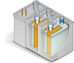
6 This document is intended to help understand our Product information and technical documentations, and make informed choices. It starts with installation hints. 1 COMMON FEATURES 1.1 Mounting Only install the charger in a pollution degree 2 environment (dry, well ventilated locations). Hang the charger vertically with the input terminal strip at the bottom. To fasten the charger on the 35 DIN rail (7.5 or 15): 1. Tilt the charger slightly rearwards 2. Fit the charger over top hat rail 3. Slide it downward until it hits the stop 4. Press against the bottom for locking 5. Shake the charger slightly to check the locking action Clearances are recommended around a charger, when it is permanently at full power, especially if it is adjacent to a heat source: Derogation: DIN modules with diode or fuse. See further. 6


. As a result, avoid recycling the power several times in a row.")
7 By design our chargers are category II regarding the installation. As illustrated for home and factory, the risk of electrical shock is higher upstream in the distribution system, especially if the location is lightning-prone: Categories according to IEC CAT II: all outlets at more than 10m from CAT III or 20m from CAT IV If the category III or IV is required, a surge protection device must be added. Ask our customer service for advice. 1.2 Definitions The individual technical documentations specify various characteristics, such as Charger inrush current: at power-on, a large pulse current is draft from the AC source for half to 1 cycle (1/ /50 ms in 50Hz). As a result, avoid recycling the power several times in a row. Besides, if several chargers are turned on at once, the high current may trip a protection; we recommend phasing in the starts Setup time: lead time after source connection Rise time: time for the output voltage to get steady Hold-up time: time when the nominal output voltage is still present after source loss Temperature coefficient: used to compensate the influence of temperature Leakage current: see the captions of the diagram blocks further (BP, BP+ and BPR B ranges) Charger efficiency: ratio of total power delivered by the charger to input power; it differs from 1 because of dissipation inside the charger Battery capacity: total charge the battery can store. The battery can deliver an energy (Wh) = average voltage x total charge (Ah). Rule of thumb: select a charger whose output current equals total charge/10 (C-rate = 0.1xC corresponding to slow charger) Charger float voltage: charge voltage at full charge 1.3 Safety issues DANGER l! HAZARD OF ELECTRIC SHOCK, EXPLOSION OR ARC FLASH The unit must only be installed and serviced by qualified electrical personnel Apply appropriate personal protective equipment (PPE), follow safe electrical work practices Turn off power before installing or removing fuses, and before installing the unit Use a properly rated voltage sensing device to confirm the power is off Do not use renewable link fuses in fused switch Failure to follow these instructions will result in death or serious injury 7
8 Connect the protective earth to ground. Isolate the charger from the AC source, before connecting or disconnecting a battery. Do not open the charger. Never charge a frozen battery. Due to a charge imbalance risk, avoid charging batteries in parallel. HAZARD OF BURN & FIRE WARNING Do not touch the unit in operation and shortly after disconnection Risk of fire and short circuit. Protect the openings from foreign objects or dripping liquids Failure to follow these instructions may result in serious injury 1.4 Charge curve The charge takes place as follows: I constant, U increases to reach the nominal power I decreases I decreases rapidly to 0 Vadjust Charge voltage Charge current Inominal Constant current Note: in the flat sections, the curve may feature a slight slope due to temperature drifts. For several types of battery and two nominal voltages, the following table shows the recommended Float and Boost voltages (Vboost is % above Vfloat). You can take either voltage for Vadjust, but Vfloat is preferred if the battery remains connected after full charge is reached. Battery rated voltage NiCd Gel /Lead-acid Vfloat Vboost Vfloat Vboost 12V 13.2V 13.8V 13.7V 14.2V 24V 26.4V 27.6V 27.4V 28.4V This table is given for information only; check with the battery manufacturer. To function as a float charger which senses the reduction in charging current and reduces the charging voltage, implement a boost strategy with a BPR B charger (see BPRB range/overview); an external logic must remove the boost on time. When the battery is used in a standby operation, such as the start of a diesel generator, the charge time does not matter a lot. It depends on the C-rate. During normal operation, the battery is at full capacity and the battery charger is used to maintain the float voltage of the battery. The battery is only drained when the generator starts. As the generator has a DC charging alternator fitted, the battery is quickly recharged when the generator is running. If the generator stops before the battery is fully recharged, the charger continues to recharge the battery until it is fully charged. 8 Constant voltage Final step 100% State of Charge
 Temperatures above the limits: NOTE General outlines are shown here. To see the accurate curves, refer to the specific Product information.")
9 1.5 Derating The performance might downgrade beyond the specified limits in the technical documentations: AC voltage below lower limit: Example: BP0524M (the AC voltage limit is 85V or 170V depending on the position of a switch) Temperatures above the limits: NOTE General outlines are shown here. To see the accurate curves, refer to the specific Product information. 9
10 1.6 Paralleling chargers For a better availability or to increase the output currents, it is advised to parallelize several chargers. Except for BP+ range (where the diode is built in), Schottky diodes must be installed so that there is no reverse current and harmonics do not add. Redundancy is also possible. The diode SBX 2550 is connected between the terminals of a DIN terminal module. The kit includes the module and the diode. The chargers are hooked up as follows (in this case, AC inputs are L1-N): L1 L1 N N F1 F2 N L1 N L1 BP XXXX BP XXXX + + F3 F4 V1 V2 + Battery F5 B+ B- B+ B- For an optimal charge: 1. Adjust to identical voltages on both chargers (at mid-run typically) 2. Connect the battery to be charged 3. Measure the current delivered by each charger 4. Increase the voltage of the charger that delivers fewer current or decrease the one of the other while keeping the correct voltage between the battery lugs; however, there is no warranty of currents balance. As a battery is connected downstream, the diode causes a voltage drop (typically 0.3V). 10
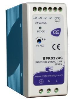
11 2 BPR (COMPACT) RANGE Diagram block: I/P = Input, FG = Front Ground, OVP = Over Voltage Protection A DC OK isolated relay output is activated in event of any fault. It is an NO contact. 2.1 Protections A Schottky diode must be installed on the output (positive terminal) to prevent reverse power in the case the battery has a higher voltage. It might result from a power outage: then the relay opens, the led goes off (unless there is no diode). The battery higher voltage might also be due to the charge by a charge alternator of a generator. Internal protections: Overcurrent: constant current limiting. The charger provides constant current even when the protection circuit is triggered; the current is clipped, until the peak disappears Short circuit: the output voltage drops; DC OK: led goes off, and the relay trips; automatic restart Overvoltage (e.g. if the connection to the battery is cut): in this event, no current is delivered; DC OK: led remains on, and relay does not trip (if the diode is installed). The charger restarts automatically Undervoltage: the relay trips until the dip disappears (above 10VDC for BPR 0324S) Reversal of polarity: if the output connections are reversed (charger > + battery), a higher current runs between charger + and battery. Therefore: WARNING THE CHARGER HAS NO FUSE ON THE OUTPUT Install a fuse on the positive output Failure to follow this instruction may damage the charger BPR 0324S 0512S Recommended fuse rating 5A 7.5A The led is still on and the relay circuit remains closed. 11

 50 N.m (4.")
12 Example of installation (the fuse and fuse module on the right are NOT provided): In this example, the diode is connected to the module on the right, but it can also span across the two smaller modules. AC side: install a fuse or a breaker on the input. The AC currents, and inrush currents in cold start, show in the data sheets. We suggest the following: BPR 0324S / 0512S Anti-surge fuse T2.5A/L250V Circuit-breaker C16. Max. count of chargers is Connections Recommended wires: made of copper, they must withstand temperatures of at least 80 C (e.g., UL1007). Cross-section and tightening torque for terminals: Cross-section Tightening torque BPR 0324S / 0512S 0.75 mm² (AWG18) 50 N.m (4.4 lb in) Make sure that all strands of each stranded wire enter the connection terminal and the screw terminals are securely fixed to prevent poor contact. 12
13 2.3 Comparison of the various models Unit BPR 0324S BPR 0512S Output Current rated/max A Voltage - rated VDC Voltage adjust range VDC Rated power W Hold-up time ms Input Voltage range V VAC, VDC Frequency range Hz Current A Inrush current (typ.) A Cold start Leakage current ma Efficiency typical,@ rated current 88% 86% Protection Overcurrent % % Short-circuit Yes Yes Overvoltage V Over temperature C Polarity reversal With fuse With fuse Functions Breaking power DC OK V 30V, 1A resistive load Temperature Working C Working humidity %RH 20 90, non condensing Storage C 40 85, %RH Coefficient %/ C 50 C WxHxD mm 40 x 90 x 100 Weight kg 0.33 MTBF C khour Vibrations 10 min/cycle, 60 min Component: 500Hz 3axes. Mounting clip compliant with IEC VDC 25 C 70%RH M >100 between input, output and front ground Max voltage VAC 3kV betw. input & output 1.5kV betw. input & ground, 0.5 kv betw. output & ground 13
14 3 BP RANGE Diagram block: I/P = Input, FG = Front Ground OVP = Over Voltage Protection OTP = Over Temperature Protection by temperature switch (detection on one or both sides of the transformer) Leakage current: the Y capacitors between I/P and FG cause some leakage current flow from line or neutral to the case; the leakage current to the case is not dangerous. A proper connection to ground discharges the case. 3.1 Protections A Schottky diode must be installed on the output (positive terminal) to prevent reverse power in the case the battery has a higher voltage (due to input outage [the led goes off unless there is no diode], or due to the charge alternator of a generator). Internal protections (the front led DC OK goes off; additionally BP 4024T lights a red led ALARM): Overcurrent: constant current limiting. The charger provides constant current even when the protection circuit is triggered; the current is clipped, until the peak disappears Short circuit: the output voltage drops; automatic restart Overvoltage (e.g. if the connection to the battery is cut): in this event, no current is delivered; the led is still on. The charger restarts automatically (if the diode is installed) Over temperature: the voltage is not delivered anymore until the fault disappears. OTP (Refer to block diagram) BP 1024M BP M BP 2024T BP 4024T Air detection x Upstream detection on heat sink of power transistor (TSW) x x x Downstream detection on heat sink of power diode (TSW2) x Reversal of polarity: if the output connections are reversed (charger > + battery), a higher current runs between charger + and battery. Therefore: WARNING THE CHARGER REQUIRES A FUSE ON THE OUTPUT Install a fuse on the positive output Failure to follow this instruction may damage the charger BP 1024M BP 0524M BP 1012M BP 2024M BP 2024T BP 4024T Recommended fuse rating 15A 7.5A 15A 25A/30A 25A/30A 50A The DC OK led is still on. 14
15 AC side: insert a breaker or fuse. The AC currents, and inrush currents in cold start, show in the data sheets. We suggest the following: BP 0524M 1012M 1024M 2024M 2024T 4024T Anti-surge fuse T4A/H250V F4A/H250V F5A/L250V T15A/H250V F6.3A/L250V F6.3A/L250V Circuit-breaker C16 Max. count of chargers is Dual phase input in Wye connection: use of only two phases BP 0524M 1012M 1024M 2024M 2024T 4024T L1-L2, L2-L3, Connections L-N L1-L3 or L3-L1 Note Phase to phase is forbidden Output current derated by 20% Example for BP 2024T: 3.2 Connections Recommended wires: made of copper, they must withstand temperatures of at least 80 C (e.g., UL1007), and have cross-sections as follows: BP 0524M 1012M 1024M 2024M/T 4024T Rated current (A) Cross-section (mm²) Cross-section (AWG) Make sure that all strands of each stranded wire enter the terminal connection and the screw terminals are securely fixed to prevent poor contact. Recommended screwdriver: 4mm, slotted type Tightening torques of terminal screws: BP 0524M and 1012M 1024M and 2024M/T 4024T AC inputs 62 N.m (5.5 lb-in) 50 N.m (4.4 lb-in) 100 N.m (9 lb-in) DC outputs 78 N.m (7 lb-in) 3.3 Power factor The power switching generates harmonics and the capacitors do not absorb currents in phase with the source. Use BP1024M or BP2024M when the power factor is a concern: BP 1024M features an active PFC function; the block diagram is similar to the one of the BPRB range (without UVP, see further). This results in a high power factor. BP 2024M features a passive PFC function (low-frequency filter between rectifiers and power switching). This results in fewer harmonics and compliance with EN standard. The efficiency is higher. 15
16 3.4 Comparison of the various models Unit BP 0524M BP 1012M BP 1024M BP 2024M BP2024T BP 4024T Output Current rated/max A Voltage - rated VDC Voltage adjust range VDC Rated power W Hold-up time ms 16@230VAC Voltage total tolerance % Input Voltage range VAC V, V switch V VAC Frequency range Hz Current A 1.7@400VAC Inrush current (typ.) Cold start A 40@230VAC Leakage current ma Power factor (typ.) none >0.99@115V Efficiency typical,@ rated current 84% 80% 84% 89% 89% 91% Protection Overcurrent %power % % % % % 0.7 Short-circuit Yes Yes Yes Yes Overvoltage V Over temperature C Polarity reversal With fuse With fuse With fuse With fuse Temperature Working C * Working humidity %RH 20 90, non condensing 20 90, non condensing Storage C C, 10 95%RH C, 10 95%RH Coefficient %/ C 50 C WxHxD mm 65.5 x x (227) x x (276) x x 100 Weight kg MTBF C khour Vibrations 10 min/cycle, 60 min Component: 500Hz 3axes. Mounting clip compliant with IEC Isolation Max VDC 25 C 70%RH M >100 between input, output and front ground VAC 3kV betw. input & output 1.5kV** betw. input & ground, 0.5 kv betw. output & ground * Derating from 55 VAC, from 40 ** 2 kv for BP 4024T 16
17 4 BP+ RANGE Diagram block: I/P = Input, FG = Front Ground OCP = Over Current Protection OVP = Over Voltage Protection OTP = Over Temperature Protection by temperature switch (sensor in air) Leakage current: the Y capacitors between I/P and FG cause some leakage current flow from line or neutral to the case; the leakage current to the case is not dangerous. A proper connection to ground discharges the case. 4.1 Protections The integral Schottky diode prevents reverse power in the case the battery has a higher voltage (due to input outage [the led goes off], or due to the charge alternator of a generator). Internal protections (the front led DC OK goes off): Overcurrent: constant current limiting. The charger provides constant current even when the protection circuit is triggered; the current is clipped, until the peak disappears Short circuit: the output voltage drops immediately; automatic restart Overvoltage (e.g. if the connection to the battery is cut): the diode limits the voltage Over temperature (detection in air): the voltage is not delivered anymore. Cycle the power. Undervoltage on output: from 2VDC, the led turns off. Cycle the power. Reversal of polarity: if the output connections are reversed ( charger to + battery), a higher current runs between charger + and battery. Therefore: WARNING THE CHARGER REQUIRES A FUSE ON THE OUTPUT Install a fuse on the positive output Failure to follow this instruction may damage the charger BP+ 0512M BP+0324M BP+1012M BP+0524M Recommended fuse rating 7.5A 5A 15A 7.5A The DC OK led is still on. 17
18 AC side: insert a breaker or fuse. The AC currents, and inrush currents in cold start, show in the technical documentations. We suggest the following: BP+ 0512M 0324M 1012M 0524M Anti-surge fuse T3.15A/L250V T4A/L250V Circuit-breaker C16 Max. count of chargers is Connections Recommended wires: made of copper, they must withstand temperatures of at least 80 C (e.g., UL1007), and have cross-sections as follows: BP+ 0512M 0324M 1012M 0524M Rated current (A) Cross-section (mm²) Cross-section (AWG) Make sure that all strands of each stranded wire enter the terminal connection and the screw terminals are securely fixed to prevent poor contact. Recommended screwdriver: 3mm, slotted type Tightening torques of terminal screws: BP+ 0512M and 0324M 1012M and 0524M AC inputs 68 N.m (6 lb-in) 100 N.m (9 lb-in) DC outputs 68 N.m (6 lb-in) 100 N.m (9 lb-in) 4.3 Comparison of the various models Refer to the Product information. 18
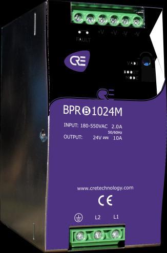
19 5 BPR B RANGE 5.1 Overview This range provides boost capability for quick charging of depleted batteries and maintenance (equalization of Pb-acid cells). This range features a small case width. Vadjust Vboost Vfloat Charge voltage Charge current Inominal For two types of battery and two nominal voltages, the following table shows the recommended Float and Boost voltages (Vboost is % above Vfloat): Battery rated voltage NiCd Gel /Lead-acid Vfloat Vboost Vfloat Vboost 12V 13.2V 13.8V 13.7V 14.2V 24V 26.4V 27.6V 27.4V 28.4V This table is given for information only; check with the battery manufacturer. From Vboost, calculate Vadjust= Vboost/1.04 (it should be close to Vfloat) and adjust the charger accordingly. Diagram blocks: Constant current Constant voltage Maintenance 100% charge BPR B 0524M and 1012M: the diagram block is similar to the one of BPR (with downstream OTP). BPR B 1024M and 2024M include in addition a dual-stage active PFC to offer a high power factor: t PFC = Power Factor Control OCP = Over Current Protection OVP = Over Voltage Protection, UVP = Under Voltage Protection OTP = Over Temperature Protection (not depicted) by upstream temperature switch (TSW): detection on heat sink of power transistor 19
20 5.2 Protections A Schottky diode must be installed on the output (positive terminal) to prevent reverse power in the case the battery has a higher voltage (due to input outage, or due to the charge alternator of a generator). Internal protections: Overcurrent: constant current limiting. The charger provides constant current even when the protection circuit is triggered; the current is clipped, until the peak disappears Short circuit: the output voltage drops; FAULT relay trips; automatic restart Overvoltage (e.g. if the connection to the battery is cut): in this event, no current is delivered; FAULT relay does not trip. To restart the charger, disconnect and reconnect the input Undervoltage: if the rectified input voltage is below a threshold, a protection is triggered (UVP of 1024M & 2024M): FAULT relay trips. If output voltage drops, the relay trips also Over temperature: the relay trips; the voltage is not delivered anymore until the fault disappears Reversal of polarity: if the output connections are reversed (charger > + battery), a higher current runs between charger + and battery. Therefore: WARNING THE CHARGER REQUIRES A FUSE ON THE OUTPUT Install a fuse on the positive output Failure to follow this instructions may damage the charger BPR B 0524M 1012M 1024M 2024M Recommended fuse rating 7.5A 15A 15A 25A/30A The DC OK isolated relay output is activated in event of any fault. AC side: insert a breaker or fuse (if in Wye connection, on L2 as illustrated). The AC currents, and inrush currents in cold start, show in the data sheets. We suggest the following ratings: BPR B 0524M,1012M, 1024M 2024M Fuse T4A/H250V T6.3A/H250V Circuit-breaker - C16 curve 10 20A 20
21 5.3 BPR B connections POWER and GROUND Recommended wires: made of copper, they must withstand temperatures of at least 80 C (e.g., UL1007), and have cross-sections as follows: BPR B 0524M 1012M and 1024M 2024M Rated current +30% (A) Cross-section (mm²) Cross-section (AWG) Make sure that all strands of each stranded wire enter the terminal connection and the screw terminals are securely fixed to prevent poor contact. BPR B 1024M and BPR B 2024M feature two outputs; use both to prevent too much current stress on a single one. STATUS and COMMAND: 0.5mm² (AWG22) Recommended screwdrivers: 3mm, slotted type, with tightening torques that follow for terminal screws: BPR B 0524M and 1012M 1024M and 2024M AC inputs 50 N.m (4.4 lb-in) 100 N.m (9 lb-in) DC outputs 78 N.m (7 lb-in) 5.4 Operation The boost can be activated: Manually through a button on another module Or automatically by an external PLC The module/plc is connected to the charger through a 2-pin block; a cord with two 30 cm (1 ) wires and a male terminal block is provided together with the charger. Procedure: 1. Connect the charger signals (status and boost command) to the module/plc 2. Connect the AC input 3. Adjust the output voltage 4. Connect the battery 5. If the boost is manually operated, press the button whenever required. 21
22 5.5 Comparison of the various models Unit BPRB 0524M BPRB 1012M BPRB 1024M BPRB 2024M Output Current rated/max A Voltage - rated VDC Voltage adjust range VDC Voltage - boost VDC When contact is closed, Vadjusted 4 5% Rated power W Hold-up time ms 18@230VAC Voltage total tolerance % Input Voltage range VAC VAC, the max. charge is derated under 200VAC Frequency range Hz Current Inrush current (typ.) A Cold start: 50A Leakage current ma Power factor (typ.) none Efficiency typical,@ rated current 90%@400VAC 88%@400VAC 90.5% 91% Protection Overcurrent %power % % % % Short-circuit Yes Yes Yes Yes Overvoltage V Over temperature C Polarity reversal With fuse With fuse With fuse With fuse Functions Breaking power FAULT V 30V / 1A resistive load Boost input 2-pin keyed front socket, module and cord (30 cm/1 ) are provided Temperature Working C Working humidity %RH 20 90, non condensing 20 95, non condensing Storage C C, 10 95%RH Coefficient %/ C 50 C WxHxD mm 40 x x x x x x Weight kg MTBF C khour Vibrations 10 min/cycle, 60 min Component: 500Hz 3axes. Mounting clip compliant with IEC Isolation Max VDC 25 C 70%RH M >100 between input, output and front ground VAC 3k betw. input & output 2k betw. input & ground, 0.5 k betw. output & ground/ FAULT 22
4 92 38 86 86 (office hours: 8.30AM - 12AM / 2PM - 6PM GMT +1) Email: support@cretechnology.com SKYPE: support-cretechnology.")
23 CRE TECHNOLOGY 130 allée Charles-Victor Naudin Zone des Templiers Sophia-Antipolis BIOT FRANCE Phone: +33 (0) Fax: +33 (0) Website: Technical support: +33 (0) (office hours: 8.30AM - 12AM / 2PM - 6PM GMT +1) support@cretechnology.com SKYPE: support-cretechnology.com (voice only) A worldwide coverage: Head Office: FRANCE Official Distributors Agents Check our entire distributors list around the world on button «DISTRIBUTORS». 23


24 BPxxxx A EN Technical addendum CRE TECHNOLOGY has provided the engine and generator industry for over 25 years with standard products and dedicated solutions for engine control, generator protection and paralleling. All application fields where power is the core resource of performance are covered by CRE TECHNOLOGY. The company is a reference in the industrial, marine and defense businesses. Our very strong situation allows us to invest, feeding our ambition to be always more advanced, always closer to you. The coming years will see the broadening of our distribution network and of our innovative products portfolio. BECOME A CRE TECHNOLOGY DISTRIBUTOR YOUR ACCOUNT & YOUR PRICES By creating your account, you ll have access to all your personal data. All the prices of the new CRE TECHNOLOGY website correspond to your business rates. GET INFORMATION THE WAY YOU WANT IT Fill your cart by choosing the products you want and get all the information you need. EVERYWHERE WITH YOU The new CRE TECHNOLOGY website is designed to be responsive to smartphones and touch tablets. It allows you to consult the documents related to the CRE TECHNOLOGY s ranges of products. 24
1000W Intelligent Single Output Battery Charger PB PB PB V 28.8V 57.6V 13.8V 85% 88% 89%
 PB000 series SPECIFICATION MODEL OUTPUT INPUT PROTECTION FUNCTION ENVIRONMENT SAFETY & EMC (Note ) OTHERS NOTE BOOST CHARGE VOLTAGE FLOAT CHARGE VOLTAGE OUTPUT CURRENT RECOMMENDED BATTERY 00 ~ 600Ah CAPACITY(AMP
 Distributed by: www.jameco.com 1-800-831-4242 The content and copyrights of the attached material are the property of its owner. PB-300 / 360 USER'S MANUAL SPECIFICATION : PB-300 MODEL BOOST CHARGE VOLTAGE
D R C- 4 0 s e r i e s
 LPS Bauart gepruft Sicherheit egelma ge od o s be wac g www. tuv.com ID 2000000000 Features Universal AC input / Full range Protections: Short circuit / Overload / Over voltage Battery low protection /
CX-SERIES ADVANCED BATTERY CHARGER
 CX-SERIES ADVANCED BATTERY CHARGER Table of Content 1. IMPORTANT SAFETY INFORMATION... 2 1-1 General Safety Precautions... 2 1-2 Battery Precautions... 2 2. FEATURES... 3 2-1 Battery Charging Curve...
BP- A Series Switch-Mode 3 Stage Battery Charger User s Manual
 BP- A Series Switch-Mode 3 Stage Battery Charger User s Manual Table of Contents 1. Important Safety Information. 1 1-1 General Safety Precautions 1 1-2 Battery Precautions..... 2 2. Features... 3 2-1
INDUSTRIAL POWER SUPPLIES SFL-SERIES
 INDUSTRIAL POWER SUPPLIES SFL-SERIES Operating Instructions 1. Application The SFL-series are compact, rugged switching power supplies designed for applications in process automation and other industrial
DIN Rail Power Supplies
 DIN Rail Power Supplies Since 1984, Altech Corporation has grown to become a leading supplier of automation and industrial control components. Headquartered in Flemington, NJ, Altech has an experienced
DPX30-xxSxx DC-DC Converter Module 9.5 ~ 18 VDC and 18 ~ 36 VDC and 36~ 75 VDC input; 3.3 to 28 VDC Single Output; 30 Watts Output Power
 DC-DC Converter Module 9.5 ~ 18 VDC and 18 ~ 36 VDC and 36~ 75 VDC input; 3.3 to 28 VDC Single Output; 30 Watts Output Power FEATURES NO MINIMUM LOAD REQUIRED 1600VDC INPUT TO OUTPUT ISOLATION SCREW TERMINALS
DPX30-xxDxx DC-DC Converter Module 9.5 ~ 18 VDC and 18 ~ 36 VDC and 36~ 75 VDC input; ±12 to ±15 VDC Dual Output; 30 Watts Output Power
 DC-DC Converter Module 9.5 ~ 18 VDC and 18 ~ 36 VDC and 36~ 75 VDC input; ±12 to ±15 VDC Dual Output; 30 Watts Output Power FEATURES NO MINIMUM LOAD REQUIRED 1600VDC INPUT TO OUTPUT ISOLATION SCREW TERMINALS
Features : 3 years warranty PB PB PB V 28.8V 57.6V 13.8V 86% 87% 89%
 600W Single Output Charger PB600 series SPECIFICATION MODEL OUTPUT INPUT PROTECTION FUNCTION ENVIRONMENT SAFETY & EMC (Note 2) OTHERS NOTE BOOST CHARGE VOLTAGE FLOAT CHARGE VOLTAGE RECOMMENDED BATTERY
Industrial Power Supplies
 , Features Switch Mode Power Supplies for DIN-rail Mounting 6 Power Ranges with 2, 3, 6, 12, 20 and 24 A Current (24 VDC Models) Selectable 115/ 230 VAC Input Very low Ripple and Noise EMI complies with
DRB-1 Series Instruction Manual
 Instruction Manual BEFORE USING THE POWER SUPPLY UNIT Pay attention to all warnings and cautions before using the unit. Incorrect usage could lead to an electrical shock, damage to the unit or a fire hazard.
Phoenix Inverter
 Manual EN Handleiding NL Manuel FR Anleitung DE Manual ES Appendix Phoenix Inverter 12 250 12 375 12 500 12 800 24 250 24 375 24 500 24 800 48 250 48 375 48 500 48 800 1. Safety instructions WARNING: ELECTRIC
User Manual. Solar Charge Controller 3KW
 User Manual Solar Charge Controller 3KW 1 CONTENTS 1 ABOUT THIS MANUAL... 3 1.1 Purpose... 3 1.2 Scope... 3 1.3 SAFETY INSTRUCTIONS... 3 2 INTRODUCTION... 4 2.1 Features... 4 2.2 Product Overview... 5
NEW The new PROmax power supplies offer a wide range of robust solutions for demanding application requirements.
 Datasheet Single- and three-phase switched-mode power supply units NEW The new power supplies offer a wide range of robust solutions for demanding application requirements. C SEMI F47 US Designed for high
DPX30-xxWDxx DC-DC Converter Module 10 ~ 40VDC, 18 ~ 75VDC input; ±12 to ±15 VDC Dual Output; 30 Watts Output Power
 DC-DC Converter Module 10 ~ 40VDC, 18 ~ 75VDC input; ±12 to ±15 VDC Dual Output; 30 Watts Output Power FEATURES NO MINIMUM LOAD REQUIRED 1600VDC INPUT TO OUTPUT ISOLATION SCREW TERMINALS FOR INPUT AND
DPX15-xxWDxx Dual Output: DC-DC Converter Module 9.5 ~ 36VDC, 18 ~ 75VDC input; ±5 to ±15 VDC Dual Output; 15 Watts Output Power
 DPX15-xxWDxx Dual Output: DC-DC Converter Module 9.5 ~ 36VDC, 18 ~ 75VDC input; ±5 to ±15 VDC Dual Output; 15 Watts Output Power FEATURES NO MINIMUM LOAD REQUIRED 1600VDC INPUT TO OUTPUT ISOLATION SCREW
DPX30-xxWSxx DC-DC Converter Module 10 ~ 40VDC, 18 ~ 75VDC input; 3.3 to 28VDC Single Output 30 Watts Output Power
 DC-DC Converter Module 10 ~ 40VDC, 18 ~ 75VDC input; 3.3 to 28VDC Single Output 30 Watts Output Power FEATURES NO MINIMUM LOAD REQUIRED 1600VDC INPUT TO OUTPUT ISOLATION SCREW TERMINALS FOR INPUT AND OUTPUT
Specifications 2019-V AC-DC Din Rail Mounted Power Supply IS-70 Series, 70W
 2019-V1.0-0318 Specifications AC-DC Din Rail Mounted Power Supply IS-70 Series, 70W No. 545 Museum Road Yangzhou, Jiangsu China 225009 Tel: 86 (514) 8279 1592 Fax: 86 (514) 8769 3159 2019 AC-DC Din Rail
Advanced Battery Charger. 3 - stage charging capability (IUoU) 25A
 25A") Cxx Features: Universal AC input with active PFC Compatible with Lead Acid, Li-ion, Gel and AGM batteries Support optional remote controller (CR-) Voltage / temperature compensation with battery temp.
Cxx Features: Universal AC input with active PFC Compatible with Lead Acid, Li-ion, Gel and AGM batteries Support optional remote controller (CR-) Voltage / temperature compensation with battery temp.
600W Intelligent Single Output Battery Charger 21A 10.5A VOLTAGE RANGE FREQUENCY RANGE
 Bauart gepruft Sicherheit egelma ge od o s be wac g 600W Intelligent Single Output Charger PB600 series SPECIFICATION SAFETY & EMC (Note 3) SAFETY STANDARDS WITHSTAND VOLTAGE ISOLATION RESISTANCE EMC EMISSION
PB-600 SERIES 600 Watt Battery Charger Power Supply Measures: 9.06 x 6.22 x 2.64
 Bauart gepruft Sicherheit egelma ge od o s be wac g www. tuv.com ID 2000000000 SPECIFICATION MODEL OUTPUT INPUT MEAN WELL PB600 SERIES PB60012 PB60024 PB60048 BOOST CHARGE VOLTAGE 14.4V 28.8V 57.6V FLOAT
MD60 Series 60W DINergy Power Supply
 MD60 Series 60W DINergy Power Supply Features Compact size, high efficiency and DIN Rail mounting 60 C rated provides full power/no derating required 100-240VAC wide-range auto-selection input Overcurrent,
Specifications 2019-V AC-DC Din Rail Mounted Power Supply IS-480 Series, 480W
 2019-V1.0-0118 Specifications AC-DC Din Rail Mounted Power Supply IS-480 Series, 480W No. 545 Museum Road Yangzhou, Jiangsu China 225009 Tel: 86 (514) 8279 1592 Fax: 86 (514) 8769 3159 2019 AC-DC Din Rail
Dycon D2430 EN54-4 Fire Alarm Power Supply Series
 Dycon D2430 EN54-4 Fire Alarm Power Supply Series Technical Description Installation and Operating Manual Construction Product Regulation 0359-CPR-00434 Page 1 of 14 Contents 1. General... 3 1.1 Product
Advanced Battery Charger 0 ~ 15A 0 ~ 25A 0 ~ 35A 0 ~ 50A 0 ~ 80A. 3 - stage charging capability (IUOU) 90 ~ 264VAC (refer to de-rating curve)
 90 ~ 264VAC (refer to de-rating curve)") Cxx Features: Universal AC input with active PFC Compatible with Lead Acid, Li-ion, Gel and AGM batteries Support optional remote controller (CR-) Voltage / temperature compensation with battery temp.
Cxx Features: Universal AC input with active PFC Compatible with Lead Acid, Li-ion, Gel and AGM batteries Support optional remote controller (CR-) Voltage / temperature compensation with battery temp.
EMERGENCY VEHICLE BATTERY MANAGER PS2024
 EMERGENCY VEHICLE BATTERY MANAGER PS2024 2 The PS2024 (Fig. 1) is designed as a on-vehicle battery charger / battery charge state monitor. While the vehicle is at its base or station, the charger is connected
Advanced Battery Charger. 3 - stage charging capability (IUOU) 4.1 A / 100VAC 1.8A / 240VAC
 4.1 A / 100VAC 1.8A / 240VAC") Cxx Features: Universal AC input with active PFC Compatible with Lead Acid, Li-ion, Gel and AGM batteries Support optional remote controller (CR-) Voltage / temperature compensation with battery temp.
Cxx Features: Universal AC input with active PFC Compatible with Lead Acid, Li-ion, Gel and AGM batteries Support optional remote controller (CR-) Voltage / temperature compensation with battery temp.
DRL-1 Series Instruction Manual
 DRL-1 Series Instruction Manual BEFORE USING THE POWER SUPPLY UNIT Pay attention to all warnings and cautions before using the unit. Incorrect usage could lead to an electrical shock, damage to the unit
UCS-CHR24V55W. Combined Power Supply & Battery Charger. Data Sheet
 Combined Power Supply & Battery Charger Data Sheet INTRODUCTION UCS-CHR24V55W is a combined charger and power supply with dedicated outputs for both charging and power supply. With a large input range
Features. Description. Table of Contents
 Features Very low profile Very high efficiency (typically 90%) Single and dual output versions Input voltages from 24V to 110VDC nominal voltages from 5V to 48VDC -40 C to +71 C operation without de-rating
Models. Output current max.* Output Power max. Low Line : VAC High Line: VAC 24 VDC / 12 A 240 W. Back up battery
 AC/DC Battery Controller Power Supply TSPC-240UPS Series Compact universal 24 VDC power supply with integrated battery controller module Battery protection for over voltage, deep discharge, short circuit
User Manual Solar Charge Controller 3KW
 User Manual Solar Charge Controller 3KW Version: 1.3 CONTENTS 1 ABOUT THIS MANUAL... 1 1.1 Purpose... 1 1.2 Scope... 1 1.3 SAFETY INSTRUCTIONS... 1 2 INTRODUCTION... 2 2.1 Features... 2 2.2 Product Overview...
Specification of Soneil Battery Charger
 SONEIL INTERNATIONAL LIMITED 6033 Shawson Dr., Unit 29, Mississauga, Ontario, Canada L5T 1H8 Ph.: (905) 565-0360 Fax: (905) 565-0352 http://www.soneil.com Revision No.: R01 06/13/2008 Specification of
Redundancy unit CP-C.1-A-RU Accessory for CP-C.1 range power supplies
 Data sheet Redundancy unit -A-RU Accessory for range power supplies ABB s redundancy units are used to establish true redundancy which increases the availability of electrical systems significantly. 2CDC
DC (on) LED Signal. Multiple output connector for easy wiring
 LED Signal. Multiple output connector for easy wiring") DIN Rail Mount, 5 x 7.5 mm or 5 x 5 mm Wide Power Range (0W-9W) Wide Adjustment Range Rugged for Industrial Use High Efficiency Lightweight and Compact Design year warranty Short Circuit Protection Overvoltage
DIN Rail Mount, 5 x 7.5 mm or 5 x 5 mm Wide Power Range (0W-9W) Wide Adjustment Range Rugged for Industrial Use High Efficiency Lightweight and Compact Design year warranty Short Circuit Protection Overvoltage
CX Series User s Manual
 CX Series User s Manual Advanced Converter / Charger Legal Provisions Copyrights 2016 COTEK Electronic IND. CO. All Rights Reserved. Any part of this document may not be reproduced in any form for any
PRO POWER 2 0 A L I T H I U M B AT T E RY C H A R G E R M O D E L : P P - L B C V E R S I O N : V 1. 0
 PRO POWER 2 0 A L I T H I U M B AT T E RY C H AR G E R M O D E L : P P - L B C - 1 2 2 0 V E R S I O N : V 1. 0 Contents 1. Revised History... 1 2. Warning... 1 3. Notes... 1 4. Product Number System...
UHP-500 series. 500W Slim Type with PFC Switching Supply
 Bauart gepruft Sicherheit egelma ge od o s be wac g www. tuv.com ID 2000000000 500W Slim Type with PFC Switching Supply S&E GB4943 UL950- EN950- IEC950- % - ~+ Industrial automation machinery Industrial
Powerterm L120C Single Output PSU/Battery Chargers Model C2199A-1 (12V/8A) or Model C2199A-2 (24V/6A)
 or Model C2199A-2 (24V/6A)") A Complete solution for small battery-backed dc instrument power systems. DATASHEET Supply 12Vdc 8A or 24Vdc 6A loads Ideal for RTU s, dataloggers, remote field instrumentation, alarm systems, etc. where
A Complete solution for small battery-backed dc instrument power systems. DATASHEET Supply 12Vdc 8A or 24Vdc 6A loads Ideal for RTU s, dataloggers, remote field instrumentation, alarm systems, etc. where
Glossary/Technical appendix
 Contents Power Supplies Overview.2 Standards and approvals.4 Glossary.6 1460790000 2014/2015.1 Power Supplies Overview Power Supplies Overview Power supplies are important links in the energy supply chain
DIN Rail UPS Model: DIN-UPS Installation/Operation Manual
 DIN Rail UPS Model: DIN-UPS 24-10 Installation/Operation Manual Table of Contents Section Page Section Page Quick Start 2 1) General Information 4 Materials Provided 4 Optional Equipment 4 2) Safety Information
Power Conversion Systems 2005/2006. Schaefer the Power to make it happen.
 Power Conversion Systems 2005/2006 Schaefer the Power to make it happen. Company profile workforce experience customer orientation flexibility reliability Schaefer Elektronik, founded in 1969, has grown
POWER SUPPLIES. Control Transformers p8-1 Modular Power Supplies p8-2 Switching Power Supplies p8-3 Automatic Battery Chargers p PAGE
 8 POWER SUPPLIES Control Transformers p8-1 Modular Power Supplies p8-2 Switching Power Supplies p8-3 Automatic Battery Chargers p8-10 Perth (08) 9248 0410 Sydney (02) 9676 1671 Melbourne (03) 9706 4599
DIN Rail UPS DC UPS/Battery Detection System Model: BDS-DIN-UPS Installation/Operation Manual
 DIN Rail UPS DC UPS/Battery Detection System Model: BDS-DIN-UPS 24-10 Installation/Operation Manual Table of Contents Section Page Section Page Quick Start 2 1) General Information 4 Materials Provided
UHP-200 series. 200W Slim Type with PFC Switching Power Supply. File Name:UHP-200-SPEC GB4943 EN EN UL IEC
 Bauart gepruft Sicherheit egelma ge od o s be wac g www. tuv.com ID 000000000 GB494 UL950- EN950- EN5- IEC950- % - ~+ R SPECIFICATION MODEL UHP-00 -. UHP-00-4. UHP-00-5 UHP-00 - UHP-00-5 UHP-00-4 UHP-00-6
DX³ RCCBs - ID 4P up to 100 A
 87045 LIMOGES Cedex Telephone number: +33 (0)5 55 06 87 87 Fax: +33 (0)5 55 06 88 88 DX³ s - ID CONTENTS PAGE 1. Description, use... 1 2. Range... 1 3. Overall dimensions... 1 4. Preparation - Connection...
TECHNICAL DATA SHEET INFINITY kva 3Ph(in) 3Ph(out)
 3Ph(out)") TECHNICAL DATA SHEET INFINITY 3300 10 15 20 kva 3Ph(in) 3Ph(out) GENERAL INFORMATION POWER - kva 10 15 20 UPS typology ON LINE Double conversion ACTIVE stand by-operation (Optional) Nominal output power
TECHNICAL DATA SHEET INFINITY 3300 10 15 20 kva 3Ph(in) 3Ph(out) GENERAL INFORMATION POWER - kva 10 15 20 UPS typology ON LINE Double conversion ACTIVE stand by-operation (Optional) Nominal output power
Uninterruptible power supplies (UPS)
") Contents Overview.2 UPS control unit.4 attery modules.6 uffer modules.8 1460790000 2014/2015.1 Overview Uninterruptible power supplies Weidmüller s uninterruptible power supplies reliably protect 24 V
Contents Overview.2 UPS control unit.4 attery modules.6 uffer modules.8 1460790000 2014/2015.1 Overview Uninterruptible power supplies Weidmüller s uninterruptible power supplies reliably protect 24 V
Sola 3000 Guide Specifications
 Sola 3000 Guide Specifications CSI 16610 - Static Uninterruptible Power Supply Systems - Sola 3000 Guide Specifications for a 700 to 2200 VA Single - Phase Uninterruptible Power Supply System 1.0 GENERAL
AUTO CHARGE 4000 MODEL #: AUTOMATIC DUAL OUTPUT BATTERY CHARGER INSTRUCTION MANUAL. Ph: Fax:
 INSTRUCTION MANUAL AUTO CHARGE 4000 AUTOMATIC DUAL OUTPUT BATTERY CHARGER MODEL #: 091-89-12 INPUT: 120 Volt, 50/60 Hz, 8 Amps OUTPUT BATTERY CHARGER: 40 Amps OUTPUT BATTERY SAVER: 5 Amps File: IM_091-89-12_reve.indd
350W Slim Type with PFC Switching Power Supply
 Bauart gepruft Sicherheit egelma ge od o s be wac g www. tuv.com ID 2000000000 350W Slim Type with PFC Switching Power Supply S&E GB4943 UL950-1 EN950-1 EN335-1 IEC950-1 % - ~+ Industrial automation machinery
QUINT-PS/24DC/24DC/20
 DC/DC converter with SFB Technology, primaryswitched, input: 24 V DC, output: 24 V DC, output current: 20 A Data sheet 104791_en_01 PHOENIX CONTACT 20130405 1 Description QUINT DC/DC converter maximum
QUINT-PS/24DC/48DC/ 5
 DC/DC converter with SFB technology, primaryswitched, input: 24 V DC, output: 48 V DC, output current: 5 A Data sheet 104793_en_01 PHOENIX CONTACT 20130503 1 Description QUINT DC/DC converter maximum system
Specification of Battery Charger
 Revision No.: 02 Specification of Battery Charger MODEL: 2460SR-1 24V / 30A IP-54 LEAD ACID BATTERY CHARGER Page 1 of 11 Contents 1. General--------------------------------------------------------------------------3
, , PREPARATION - CONNECTION. Mounting:. On symmetrical EN rail or DIN 35 rail
 87045 LIMOGES Cedex Telephone number: +33 (0)5 55 06 87 87 Fax: +33 (0)5 55 06 88 88 DX 3 4500 A / 6 ka CONTENTS PAGES 1. Description, use...1 2. Range...1 3. Overall dimensions...1 4. Preparation - Connection...1
Specification of Battery Charger
 1 S O N E I L 6033 Shawson Dr., Unit 29, Mississauga, Ontario, Canada L5T 1H8 Ph.: (905) 565-0360 Fax: (905) 565-0352 http://www.soneil.com Revision No.: R01 Specification of Battery Charger MODEL: 6010SR
LPF-25 series. 25W Constant Voltage + Constant Current LED Driver
 F 110 M M SELV IP67 Features Constant Voltage + Constant Current mode output Plastic housing with Class II design Built-in active PFC function Class 2 power unit Fully encapsulated with IP67 level Typical
PB -300 / 360 Instruction Manual
 PB -0 / 360 Instruction Manual PB-0,360 Instruction Manual ON/OFF SWITCH 2/115VAC SWITCH 2 INLET 3 POLE IEC320 C14 Battery Connection LED +V -V SVR1 CN5 Vadj VR RC DC (+) DC (-) WARNING : Please make sure
Manual. EN Appendix. Lynx Ion BMS 400A / 1000A
 Manual EN Appendix Lynx Ion BMS 400A / 1000A 1. SAFETY INSTRUCTIONS 1.1 In general Please read the documentation supplied with this product first, so that you are familiar with the safety signs en directions
150 WATT HEW SINGLE SERIES DC/DC CONVERTERS
 Features Description The 4:1 Input Voltage 150 W single HEW Series of DC/DC converters provide precisely regulated dc outputs. The output voltage is fully isolated from the input, allowing the output to
PB-600 Instruction Manual
 PB600 Instruction Manual PB600 Instruction Manual Index 0.Product description... 1 1.Notes on operation... 1 2.Front and back panel... 1 3.Derating curve... 2 3.1 Charging current VS temperature... 2 3.2
UHP-350 series. 350W Slim Type with PFC Switching Power Supply
 Bauart gepruft Sicherheit egelma ge od o s be wac g www. tuv.com ID 2000000000 50W Slim Type with PFC Switching Power Supply GB494 UL950-1 EN950-1 EN5-1 IEC950-1 - ~ Industrial automation machinery Industrial
Sorensen XG 1700 Series 1700 W A Watt, 1U Programmable DC Power Supplies V. Key Features. Key Modes
 Sorensen XG 1700 Series 1700 W 1700 Watt, 1U Programmable DC Power Supplies 6 600 V Industry Leading Power Density Up to 1700 Watts in 1U Standard Digital Interfaces USB&RS232/485 LXI Ethernet and Isolated
ST - II Series POWER SUPPLIES USER INSTRUCTIONS
 Introduction ST - II Series POWER SUPPLIES These instructions detail the installation and operation requirements for the ST20-II & ST35-II power supplies. These have been designed for operation in RV s
Phase + Neutral, neutral on left side
 87045 LIMOGES Cedex Téléphone : 05 55 06 87 87 Télécopie : 05 55 06 88 88 DX 3 MCB 10000 A / 16 ka CONTENTS PAGE 1. Description, use...1 2. Range...1 3. Overall dimensions...1 4. Preparation - Connection...1
AC CONVERTER / BATTERY CHARGER
 AC CONVERTER / BATTERY CHARGER User s Manual MODEL #: CON120AC12/24VDC Listed to UL 458 and CSA 22.2 NO. 107.1 Standards Contents INTRODUCTION... 3 Important Safety Instructions... 3 1. General Description...
PUMP PLUS 2000 PLC MODEL #: PP AUTOMATIC DUAL OUTPUT BATTERY CHARGER INSTRUCTION MANUAL
 INSTRUCTION MANUAL PUMP PLUS 2000 PLC AUTOMATIC DUAL OUTPUT BATTERY CHARGER Supplied with Dual Bar Graph Display MODEL #: 091-237-12-PP INPUT: 120 Volt, 60 Hz, 3.5 Amps OUTPUT BATTERY 1 and 2: 15 or 18
Sola/Hevi-Duty S3K Series Mini-Tower UPS
 Sola/Hevi-Duty S3K Series Mini-Tower UPS GUIDE SPECIFICATIONS 700VA to 1600VA 120V models Single - Phase Uninterruptible Power Supply Systems 1.1 SUMMARY 1.0 GENERAL This specification defines the electrical
AUTO CHARGE D PUMP PLUS
 INSTRUCTION MANUAL AUTO CHARGE D PUMP PLUS AUTOMATIC DUAL OUTPUT BATTERY CHARGER Designed Specifically for Vehicles with DDEC ENGINES MODEL #: 091-9-DPP INPUT: 120 Volt, 60 Hz, 8 Amps OUTPUT VEHICLE BATTERY:
Art. No. EC-315. Art. No. EC-330. Art. No. EC-340 SWITCH-MODE BATTTERY CHARGER CONTENTS IMPORTANT SAFETY PRECAUTIONS... 2
 SWITCH-MODE BATTTERY CHARGER CONTENTS IMPORTANT SAFETY PRECAUTIONS... 2 DESCRIPTION AND FEATURES... 3 CHARGING STAGES... 4 Art. No. EC-315 Art. No. EC-330 Art. No. EC-340 PROTECTIONS... 5 INSTALLATION...
AUTO CHARGE D2 MODEL #: AUTOMATIC TRIPLE OUTPUT BATTERY CHARGER INSTRUCTION MANUAL
 INSTRUCTION MANUAL AUTO CHARGE D2 AUTOMATIC TRIPLE OUTPUT BATTERY CHARGER Designed Specifically for Vehicles with DDEC ENGINES MODEL #: 091-74-12 INPUT: 120 Volt, 60 Hz, 8 Amps OUTPUT VEHICLE BATTERY 1
Phase + Neutral, neutral on right side
 87045 LIMOGES Cedex Telephone number: +33 5 55 06 87 87 Fax: +33 5 55 06 88 88 DX 3 MCB 6000 A / 10 ka Cat.. N (s): 4 074 67 / 68 / 69 / 70 / 71 / 72 / 73 / 74 / 75 / 76 / 77 / 78 / 79 ; 4 077 33 / 34
RWS50B RWS100B RWS150B RWS300B RWS600B
 RWS-B Series 50W to 600W Single Output General Purpose Power Supplies Features 10 Year e-cap Lifetime 7 Year Warranty Global Safety Approvals Compact Size Better Field Reliability Lower Cost of Ownership
SELV IP30 (CCC optional)
") Features Constant Voltage + Constant Current mode output Plastic housing with Class II design Built-in active PFC function Class 2 power unit Fully encapsulated with IP30 level, optional IP67 rating Typical
Features Constant Voltage + Constant Current mode output Plastic housing with Class II design Built-in active PFC function Class 2 power unit Fully encapsulated with IP30 level, optional IP67 rating Typical
Ordering Information. Switching Power Supply S82F. Industrial-Grade Power Supply for General or Peak Load Applications SWITCHING POWER SUPPLIES
 Switching Power Supply S82F Industrial-Grade Power Supply for General or Peak Load Applications Correct input voltage range is automatically selected: 1 VAC or 2 VAC. Model S82F-P is suitable for peak
TX³ RCCBs 2P up to 100 A
 87045 LIMOGES Cedex Telephone number: +33 (0)5 55 06 87 87 Fax: +33 (0)5 55 06 88 88 TX³ RCCBs CONTENTS PAGE 1. Description, use... 1 2. Range... 1 3. Overall dimensions... 1 4. Preparation - Connection...
AUTO CHARGE 4000 MODEL #: LOW PROFILE CHARGER AUTOMATIC DUAL OUTPUT BATTERY CHARGER INSTRUCTION MANUAL
 INSTRUCTION MANUAL AUTO CHARGE 4000 LOW PROFILE CHARGER AUTOMATIC DUAL OUTPUT BATTERY CHARGER Unit supplied with this display MODEL #: 091-89-12 INPUT: 120 Volt, 50/60 Hz, 5 Amps OUTPUT: 45 Amps File:
DNX 3 MCB 4500 A / 6 ka Phase + Neutral, neutral on left side
 87045 LIMOGES Cedex Telephone number: +33 (0)5 55 06 87 87 Fax: +33 (0)5 55 06 88 88 DNX 3 MCB 4500 A / 6 ka CONTENTS PAGE 1. Description, use... 1 2. Range... 1 3. Overall dimensions... 1 4. Preparation
MB A 12V/24V DC PROGRAMMABLE DUAL BATTERY ISOLATOR
 MB-3688 120A 12V/24V DC PROGRAMMABLE DUAL BATTERY ISOLATOR User Manual Warning and Precautions MB-3688 is built with corrosion resistant material and the main electronic assembly is well sealed inside
UZK12.071, UZO GENERAL DESCRIPTION 2. DATA 3. ORDER NUMBERS 4. MARKINGS BATTERY MODULE BATTERY MODULE 12V, 7AH 1/9.
 BATTERY MODULE Two Mounting Options: DIN-Rail or Panel/ Wall Mounting IP00 Open Type Protection Level Easy Access to the Terminals and the Fuse Heavy Duty Fuse Holder and Spare Fuse Included UZK12.071
Industrial Chargers and
 Industrial Chargers and DC Systems SPR - Single Phase Rectifier TPR - Three Phase Rectifier 12V 250V 5A 1000A Designed for all Industrial applications Oil & Gas, Petrochemicals Offshore, Onshore, Pipelines
Innovative Circuit Technology Ltd.
 Innovative Circuit Technology Ltd. IntelliCharge Battery Charger Series INSTRUCTION MANUAL 855-342-000 Models: ICT24012-30BC2, ICT24012-30BC2M ICT24012-15BC2, ICT24012-15BC2M ICT24024-15BC2, ICT24024-15BC2M
GB60S 60W Single Output General Purpose Series
 Features 2 x 3 x 1.0 Package Operates to 80 C Ambient For 1U Applications 60W convection cooled Universal Input 90-264Vac Optional Power ON LED Approved to CSA/EN/IEC/UL60950-1, 2 nd Edition Efficiency
MODEL SELECTION TABLE Open Frame Models. MODEL SELECTION TABLE U-Chassis Models. MODEL SELECTION TABLE Enclosed Models
 Open Frame ( O Type) U-Chassis ( U Type) Enclosed ( C Type) DIN Rail Kit ( DN Type) Size: 5in x 3in x 1.16~1.24in (127mm x 76.2mm x 29.5~31.5mm) Size: 5in x 3~3.23in x 1.5in (127mm x 76.2~82.2mm x 38.1mm)
ATS22D88Q soft starter-ats22-control 220V-power 230V (22kW)/ V(45kW)
/ V(45kW)") Product datasheet Characteristics ATS22D88Q soft starter-ats22-control 220V-power 230V (22kW)/400...440V(45kW) Complementary Assembly style Function available Supply voltage limits Main Range of product
Product datasheet Characteristics ATS22D88Q soft starter-ats22-control 220V-power 230V (22kW)/400...440V(45kW) Complementary Assembly style Function available Supply voltage limits Main Range of product
QUINT-PS/24DC/24DC/10
 DC/DC converter with SFB Technology, primaryswitched, input: 24 V DC, output: 24 V DC, output current: 10 A Data sheet 104790_en_01 PHOENIX CONTACT 20130405 1 Description QUINT DC/DC converter maximum
Dycon D1532SM. EN50131/PD6662 Grade 3, 12V 2A Power Supply. Technical Description Installation and Operating Manual DYCON POWER SOLUTIONS LTD
 Dycon D1532SM EN50131/PD6662 Grade 3, 12V 2A Power Supply Technical Description Installation and Operating Manual DYCON POWER SOLUTIONS LTD Tel: +44 (0)1443 471 900 Unit A Cwm Cynon Business Park Mountain
Specification of Soneil Battery Charger
 SONEIL INTERNATIONAL LIMITED 3 180 Advance Blvd., Brampton, Ontario, L6T 4J4 Ph.: 905-565-0360 Fax: 905-799-6821 http://www.soneil.com Specification of Soneil Battery Charger MODEL: CS3603SR 36V1.2A BATTERY
UZK12.071, UZO DATA 1. GENERAL DESCRIPTION 4. MARKINGS 3. ORDER NUMBERS PASSIVE BATTERY MODULE BATTERY MODULE 12V, 7AH 1/9.
 PASSIVE BATTERY MODULE Two Mounting Options: DIN-Rail or panel/wall mounting IP00 Open Type Protection Level Easy Access to the Terminals and the Fuse Heavy Duty Fuse Holder and Spare Fuse Included 1.
QUINT-PS/24DC/24DC/ 5/CO
 DC/DC converter with SFB technology, dip-coated, primary-switched, input: 24 V DC, output: 24 V DC, output current: 5 A Data sheet 105537_en_01 PHOENIX CONTACT 2014-02-13 1 Description QUT DC/DC converter
Specification of Soneil Battery Charger MODEL: 5807SR 60V5A BATTERY CHARGER
 SONEIL INTERNATIONAL LIMITED 3 180 Advance Blvd., Brampton, Ontario, L6T 4J4 Ph.: 905-565-0360 Fax: 905-799-6821 http://www.soneil.com Specification of Soneil Battery Charger MODEL: 5807SR 60V5A BATTERY
IS 15885(Part 2/Sec13) R ( for 24V only)
 R ( for 24V only)") THOMAS SAMUEL THOMAS SAMUEL Bauar t gepruft Sicherheit egel ma ge od o s be wac g W Constant Voltage + Constant Current LED Driver 110 M IP67 Features Constant Voltage + Constant Current mode output Plastic
THOMAS SAMUEL THOMAS SAMUEL Bauar t gepruft Sicherheit egel ma ge od o s be wac g W Constant Voltage + Constant Current LED Driver 110 M IP67 Features Constant Voltage + Constant Current mode output Plastic
Features. LED Driver. RACT09 9 Watt. TRIAC Dimmable. Single Output RACT09- AC/DC Converter
 Features TRIAC Dimmable LED Driver Triac dimmable with leading or trailing edge dimmers Class II with SELV output (no earth required) Extra-large screw terminals and integrated cable clamps for easy installation
PUMP PLUS 1000 PLC MODEL #: PP AUTOMATIC SINGLE OUTPUT BATTERY CHARGER INSTRUCTION MANUAL
 INSTRUCTION MANUAL PUMP PLUS 1000 PLC AUTOMATIC SINGLE OUTPUT BATTERY CHARGER Unit supplied with one of these displays MODEL #: 091-215-12-PP INPUT: 120 Volt, 60 Hz, 3.5 Amps OUTPUT BATTERY 1 and 2: 15
Smart Battery Charger
 BATTERY CHARGER Smart Battery Charger Model No. WSC-1215 (SB) WSC-1230 (SB) WSC-2408 WSC-2415 Manual Please read this manual carefully before installing and starting up this device. Figure 1 WSC-1215SB
Electrical network protection VIP30, VIP35. User s manual 12/2008
 Electrical network protection VIP30, VIP35 User s manual 1/008 Safety instructions ANSI symbol. IEC symbol. Safety symbols and messages Read these instructions carefully and look at the equipment to become
USER S MANUAL GPC SERIES LOW VOLTAGE DISCONNECT. Galley Power LLC.
 USER S MANUAL GPC SERIES LOW VOLTAGE DISCONNECT Galley Power LLC www.galleypower.com Table of Contents Safety Notice... 3 Disclaimer... 3 Safety Instructions... 4 1. Introduction... 5 1.1 Features and
RX 3 MCB 4500 A Phase + Neutral, neutral on left side
 87045 LIMOGES Cedex Téléphone : 05 55 06 87 87 Télécopie : 05 55 06 88 88 RX 3 MCB 4500 A CONTENTS PAGE 1. Description, use... 1 2. Range... 1 3. Overall dimensions... 1 4. Preparation - Connection...
DC POWER SUPPLY SYSTEMS
 DC POWER SUPPLY SYSTEMS double branch Rectifier - SCR type TITANIUM 2R-SCR PLUS SERIES TITANIUM 2R-SCR rectifier series belongs to the Double Branch category thus provided with two independent AC / DC